

Page 1
OPERATOR’S MANUAL
CSV 260
CHIPPER-VACUUM
IMPORTANT: READ SAFETY RULES AND INSTRUCTIONS CAREFULLY
Warning:
covered, brush-covered or grass-covered land unless the engine’s exhaust system is equipped with a spark arrester meeting
applicable local or state laws (if any). If a spark arrester is used, it should be maintained in effective working order by the operator.
In the State of California the above is required by law (Section 4442 of the California Public Resources Code). Other states may have
similar laws. Federal laws apply on federal lands. A spark arrester for the muffler is available through your nearest engine authorized
service dealer or contact the service department, P.O. Box 368023 Cleveland, Ohio 44136-9722.
This unit is equipped with an internal combustion engine and should not be used on or near any unimproved forest-
CUB CADET CORP. P.O. BO X 368023 CLEVELAND, OHIO 44136-9722
PRINTED IN U.S.A. FORM NO. 770-10053A
(5/99)
Page 2

SECTION 1: IMPORTANT SAFE OPERATION PRACTICES
WARNING: THIS SYMBOL POINTS OUT IMPORTANT SAFETY INSTRUCTIONS WHICH, IF
NOT FOLLOWED, COULD ENDANGER THE PERSONAL SAFETY AND/OR PROPERTY OF
YOURSELF AND OTHERS. READ AND FOLLOW ALL INSTRUCTIONS IN THIS MANUAL
BEFORE ATTEMP TING TO O PERATE YOU R CHIPPER -VACUU M. FAILURE TO COMPLY WITH
THESE INSTRUCTIONS MAY RESULT IN PERSONAL INJURY. WHEN YOU SEE THIS
SYMBOL-HEED ITS WARNING.
WARNING: The Engine Exhaust from this product contains chemicals known to the State of
California to cause cancer, birth defects or other reproductive harm.
DANGER: Your chipper-vacuu m was buil t to be ope rated acc ordin g to the rules for safe ope ratio n
in this manual. As with any type of power equipment, carelessness or error on the part of the
operator can result in serious injury. This unit is capable of amputating fingers and hands and
throwing objects. Fai lure to observe the fol lowing safety ins tructions could re sult in serious in jury or
death.
1. GENERAL OPERATION
• Read this operator's manual carefully in its entirety
before attempting to assemble this machine. Read,
understand, and follow all instructions on the
machine and in the manual(s) before operation. Be
completely familiar with the controls and the proper
use of the machine before operating it. Keep this
manual in a safe place for future and regular
reference and for ordering replacement parts.
• Your chipper-vacuum is a powerful tool, not a
plaything. Therefore, exercise extreme caution at
all times. Your unit has been designed to perform
two jobs; to chip and vacuum vegetation found in a
normal yard. Do not us e it for any other purpose.
• Never allow children under 16 to operate the unit.
Children 16 years and older should only operate
under close parental supervision. Only responsible
individuals who are familiar with these rules of safe
operation should be allowed to use your unit.
• Keep the area of operation clear of all persons,
particularly small children and pets. Stop the
engine when they are in the vicinity of the unit.
• When feeding material into this equipment, be
extremely careful that pieces of metal, rocks,
bottles, cans or other foreign objects are not
included. Personal injury or damage to the machine
could result.
• Always wear safety glasses or safety goggles,
during operation and while performing an
adjustment or repair, to protect eyes from foreign
objects that may be thrown from the machine.
• Wear sturdy, rough-soled work shoes and close
fitting sla cks and shirt. Shirt and slacks that cover
the arms and legs and steel-toed shoes are
recommended. Do not wear loose fitting clothes or
jewelry, and secure hair above shoulder length.
They can be caught in moving parts. Never operate
a unit in bare feet, sandals or sneakers. Wear
gloves when feeding material in the chipper chute.
• Do not operate the unit while under the influence of
alcohol or drugs.
• Do not overreach. Keep proper footing and balance
at all times.
• Never place your hands or any part of your body or
clothing near or under rotating parts. Keep clear of
the discharge opening at all times Never insert
your hands or any part of your body or clothing into
the nozzle, chipper chute or discharge opening as
the rotating impeller can cause serious injury.
• If it is necessary for any reason to unclog the feed
intake or discharge openings or to inspect or repair
any part of the machine where a moving part can
come in contact with your body or clothing, stop the
machine, allow it to cool, disconnect the spark plug
wire from the spark plug and move it away from the
spark plug before attempting to unclog, inspect or
repair.
• Never operate unit without vacuum bag and
discharge chute properly affixed to unit. Large
zippered end of bag must be closed to prevent
objects from being blown out.
• Never operate unit without either the inlet nozzle or
optional hose attachment properly affixed to unit.
These devi ces shield the operat or from accidental
contact with the rotating impeller. Never attempt to
convert the unit from nozzle to hose mode or vice
versa with the engine running.
• Never attempt to remove or empty vacuum bag
when engine is running. Shut the engine off and
wait for the impeller to come to a complete stop
before removing the bag. The impeller continues to
rotate for a few seconds after the engine is shut off.
Never place any part of the body in the impeller
area until you are sure the impeller has stopped
rotating.
• Keep all guards and safety devices in place and
operating properly.
2
Page 3

• Do not allow an accumulation of processed
material to build up in the discharge area as this
will prevent proper discharge and can result in
kickback from the chipper chute.
• Keep your face and body back from chipper chute
to avoid accidental bounce back of any material.
• If the cutting mechanism strikes a foreign object or
if your machine should start making an unusual
noise or vibration, immediately stop the engine,
disconnect the spark plug wire and move the wire
away from the spark plug. Allow the machine to
stop and take the following steps.
• Inspect for damage
• Repair or replace any damaged parts.
• Check for any loose parts and tighten to
assure continued safe operation.
• Muffler and engine become hot and can cause a
burn. Do not touch.
• Do not allow leaves or other debris to build up on
engine’s muffler. The debris could ignite and cause
a fire.
• Do not operate engine if air cleaner or cover over
carburetor air intake is removed, except for
adjustment. Removal of such parts could create a
fire hazard.
2. CHILDREN
Tragic accidents can occur if the operator is not alert to the
presence of small children. Children are often attracted to
the chipping and vacuuming activity. Never assume that
children will remain where you last saw them.
• Keep children out of the work area and under the
watchful eye of a responsible adult other than the
operator.
• Be alert and turn the unit off if a child enters the
area.
• Never allow children under the age of 16 to operate
the chipper-vacuum.
3. SERVICE
• Use extreme care in handling gasoline and other
fuels. They are extremely flammable and the
vapors are explosive.
• Store fuel and oil in approved containers, away
from heat and open flame, and out of the reach of
children.
WARNING - YOUR RESPONSIBILITY: Restrict the use of this power machine to persons who
read, understand and follow the warnings and instructions in this manual and on the machine.
• Check and add fuel before starting the engine.
Never remove gas cap or add fuel while the engine
is running. Allow engine to cool at least two
minutes before refueling.
• Replace gasoline cap securely and wipe off any
spilled gasoline before starting the engine as it may
cause a fire or explosion.
• Extinguish all cigarettes, cigars, pipes and other
sources of ignition.
• Never refuel unit indoors because flammable
vapors will accumulate in the area.
• Never store the machine or fuel container inside
where there is an open flame or spark such as a
gas hot water heater, clothes dryer or furnace.
• Never run your machine in an enclosed area as the
exhaust from the engine contains carbon
monoxide, which is a odorless, tasteless and
deadly poisonous gas.
• To reduce fire hazard, keep engine and muffler free
of leaves, grass, and other debris build-up. Clean
up fuel and oil spillage. Allow unit to cool at least 5
minutes before storing.
• Before cleaning, repairing, or inspecting, make
certain the impeller and all moving parts have
stopped. Disconnect the s park plug wire and keep
wire away from spark plug to prevent accidental
starting. Do not use flammable solutions to clean
air filter.
• Keep all nuts, bolts, and screws tight to be sure the
equipment is in safe working condition.
• Never tamper with safety devices. Check their
proper operation regularly.
• After striking a foreign object, immediately stop the
engine, disconnect the spark plug wire from the
spark plug, and thoroughly inspect the unit for any
damage. Repair damage before starting and
operating unit.
• Do not alter or tamper with the engine’s governor
setting. The governor controls the maximum safe
operating speed of the engine. Overspeeding the
engine is dangerous and will cause damage to the
engine and to other moving parts of the machine.
• Check the vacuum bag frequently for wear.
Replace if worn or damaged.
• Keep vacuum bag free of debris when not in use.
3
Page 4
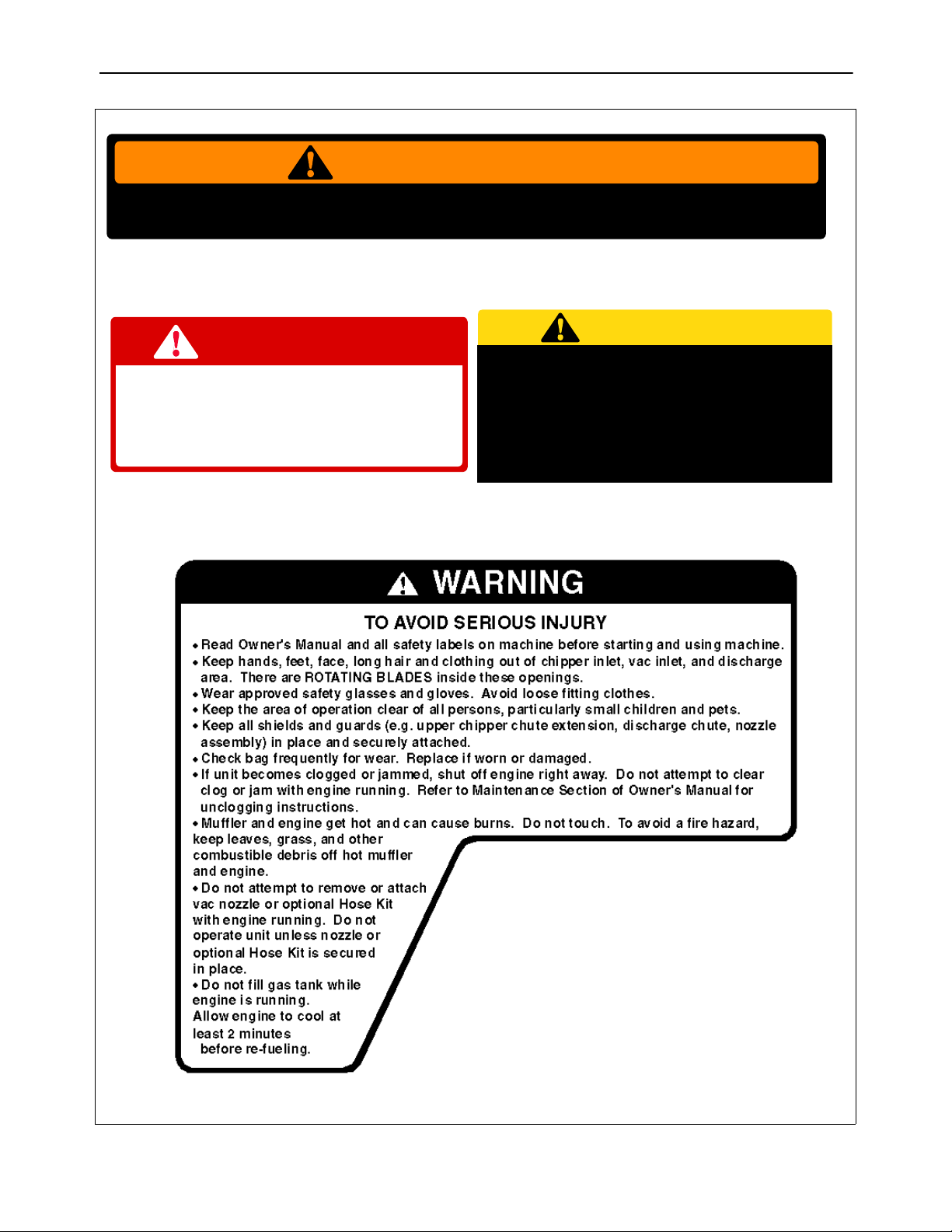
SECTION 2: SAFETY LABELS FOUND ON YOUR UNIT.
WARNING
ROTATING BLADES INSIDE. KEEP HANDS AWAY FROM ALL OPENINGS. DO NOT
REMOVE OR ATTACH NOZZLE OR OPTIONAL HOSE KIT WHEN ENGINE IS RUNNING!
CAUTION
DANGER
ROTATING CUTTING BLADES.
KEEP HANDS AND FEET OUT
OF OPENINGS WHILE MACHINE
IS RUNNING.
S30181
DO NOT OPERATE THIS UNIT WITHOUT
ENTIRE BAG AND DISCHARGE CHUTE
IN PLACE. TURN THE ENGINE OFF AND
ALLOW THE IMPELLER TO COME TO A
COMPLETE STOP BEFORE REMOVING
THE BAG.
S30183
S30131
4
Page 5
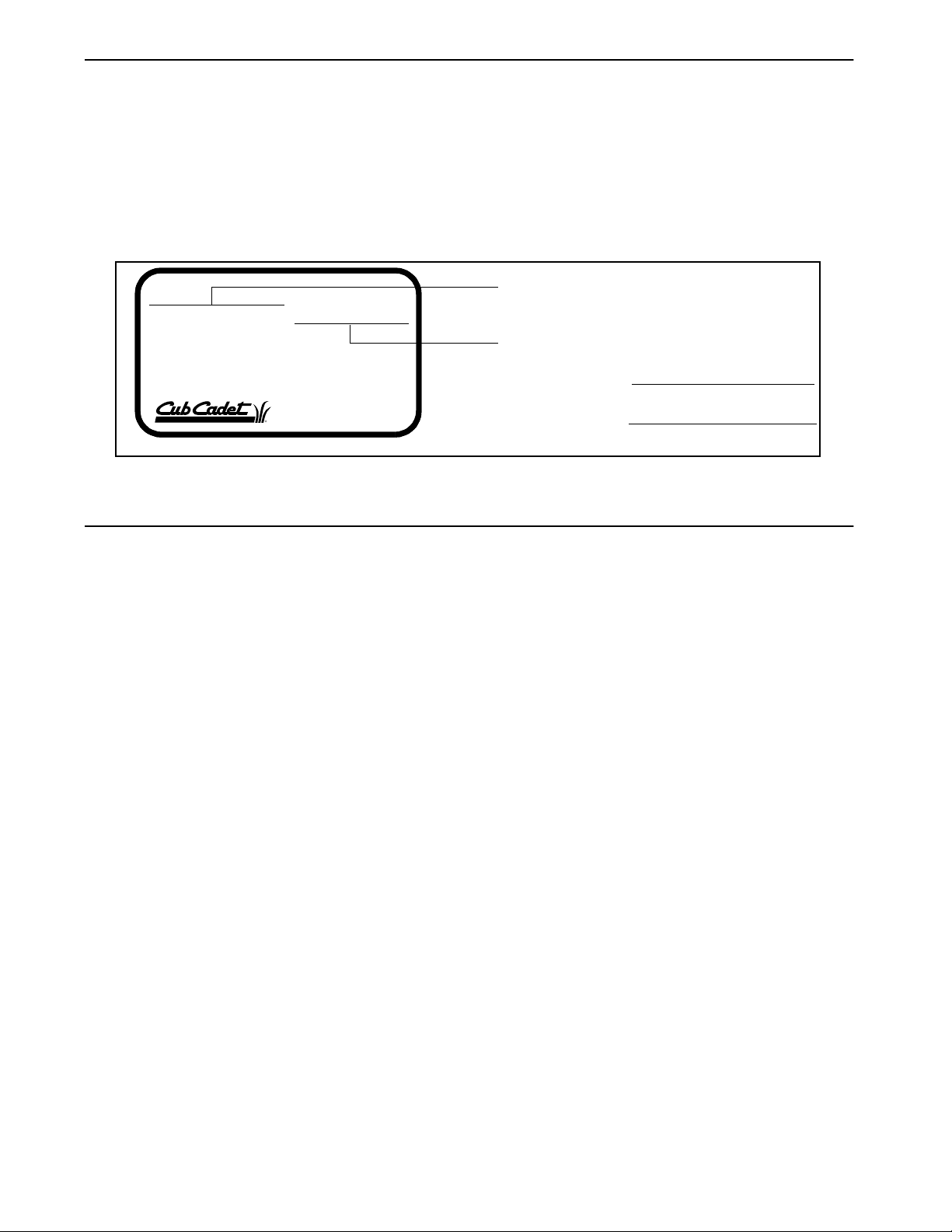
SECTION 3: FINDING YOUR MODEL NUMBER
This Operator’s Ma nua l i s an important part of y ou r new ch ipp er -vac uu m. I t wi ll hel p y ou ass emb le, prepare and
maintain your chipper-vacuum. Please read and understand what it says.
Before you prepare y our c hip per -va cu um fo r it s fir s t use, pl ea se l oc ate the m ode l pl ate and c op y th e in for ma tio n
from it in this Operator’ s Manual. The information on the model pl ate is very important if you need help from
your dealer or Customer Support Department.
• Every chipper-vacuum has a model p late. You can locate it by standi ng behind the unit in the operatin g
position and looking down at the frame just below the engine.
• The model plate will look like this.
This is where your model number will be.
XXX-X-XXX-X-XXX XXXXXXXXXXX
This is where your serial number will be.
Copy the model number here:
CUB CADET CORP .
P. O. BOX 368023
CLEVELAND, OHIO 44136
Copy the serial number here:
SECTION 4: CALLING WARRANTY SERVICE
If you are having d ifficult y assembl ing this product o r if yo u have a ny ques tion reg arding t he controls , opera tion
or maintenance of th is chipper-v accum, pleas e call the Cus tomer Deale r Referral Lin e. You can re ach them by
calling:
1-800-528-1009
Before calling your local dealer , make sure that you have your model an d serial numbe rs ready. By havin g the
model and serial num bers ready, you help your local d ealer give you faster servic e. To find your units model
and serial number, see SECTION 3: FINDING YOUR MODEL NUMBER.
5
Page 6
SECTION 5: ASSEMBLY INSTRUCTIONS
IMPORTANT: This unit is shipped WITHOUT
GASOLINE or OIL in the engine. After assembly,
see separate engine manual for proper fuel and
engine oil recommendations.
NOTE: To det ermine right and left hand side s of your
chipper-vacuum, stand behind and face the unit.
TO REMOVE CHIPPER-VACUUM FROM
CARTON
1. Remove staples, break glue on top flaps, or cut
2. Remove loose parts if included with unit (i.e.,
3. Cut corner’s and lay carton down flat.
4. Remove packing material.
5. Push down on handle to lift the front of the
TOOLS REQUIRED FOR ASSEMBLY
(1) 3/4" Open End Wrench* (2) 1/2" Wrenches*
(1) Funnel (1) 9/16" Wrench*
(1) Set of Pliers (2) 7/16" Wrenches*
*Adjustable wrenches may be used.
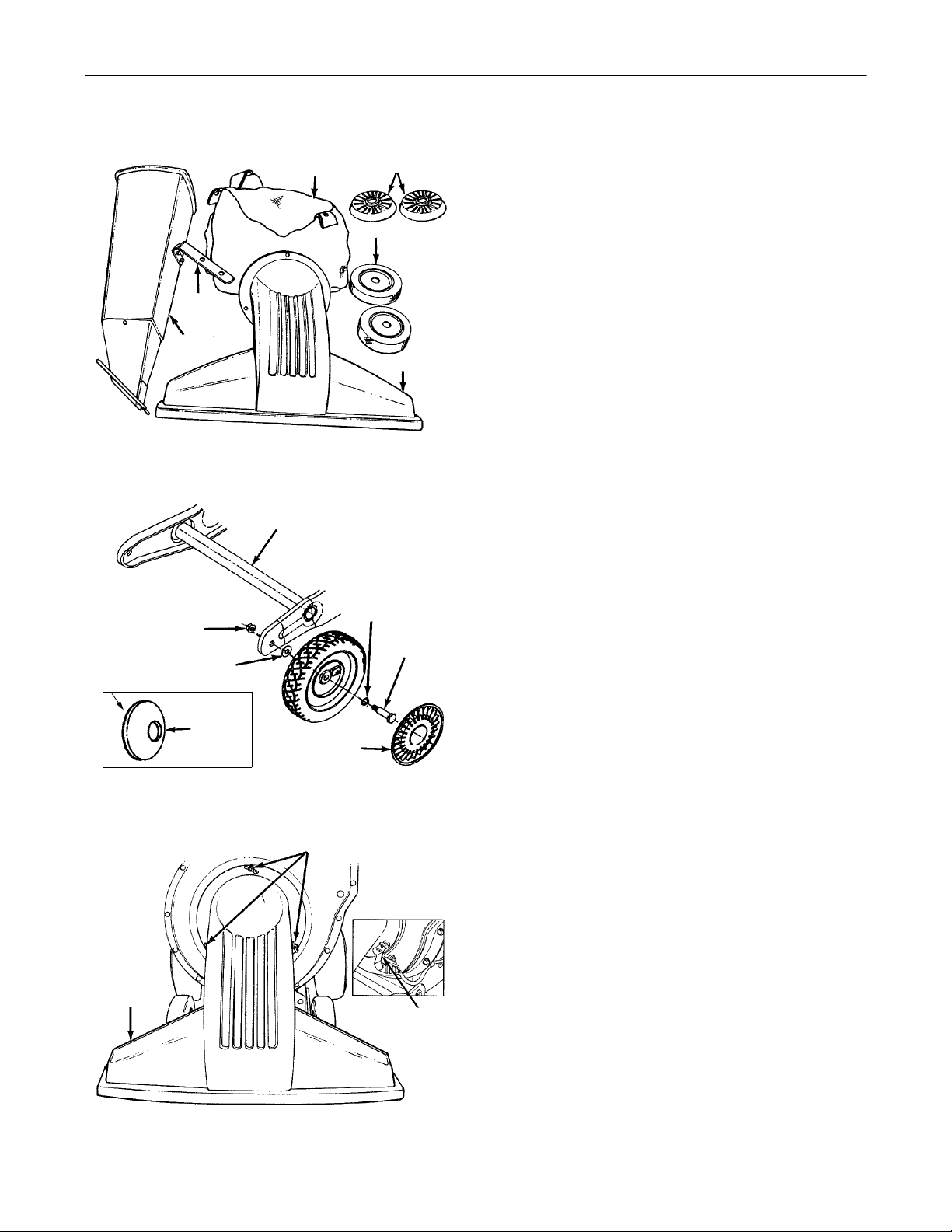
LOOSE PARTS IN CARTON (See Figure 1)
(2) Front Wheels (1) Bag
(2) Hub Caps (1) Shift Knob†
(1) Nozzle (1) Tamper Plug† (Opt.)
(1) Chipper Chute (1) Safety Glasses†
(1) Support Bracket
†Not Shown
ATTACHING THE FRONT WHEELS
1. Tilt unit backward so that it rests on the handle
2. Remove the hex lock nuts and s houlder bolts from
3. Place wave washer on shoulder bolt. Insert
4. Place cupped washer on shoulder bolt (crowned
5. Assemble wheel to outside of wheel bracket.
6. Attach hub caps to wheels by placing in position
ATT ACHING THE NOZZLE (See Figure 3)
1. Remove three wing nuts from the front of the
NOTE: The metal tab on the nozzle must depress the
safety switch on the front of th e chipper-vacuum or the
engine will not start.
2. Set unit in upright position.
Cupped
Side
Nozzle
Support
Bracket
Chipper
Chute
Hex Lock
Nut
Cupped
Washer
Crowned
Side
Bag
Figure 1
Wheel Bracket
Figure 2
Wing Nuts
Figure 3
Hub Caps
Front Wheels
Nozzle
Wave
Washer
Shoulder
Bolt
Hub
Cap
Metal Tab
tape at carton end and peel along top flap to open
carton.
operator’s manual, etc.).
chipper-vacuum, a nd roll unit ou t of carton. Check
carton thoroughly for loose parts.
(place a piece of th e carton under h andle to avoid
scratches). Remove the cardboard packing
material around the wheel brackets.
the front of the wheel brackets. See Figure 2.
shoulder bolt through wh eel, with the head of the
shoulder bolt through the flat side of the wheel.
side of washer goes against the wheel).
Secure hex lock nut. Tighten.
against the inner hub of the wheel. Press firmly
around the center portion of hub cap in a c ircular
motion, similar t o ins talli ng a l id on a round, pla stic
container. The hub caps ar e flexible and will snap
over the wheel hubs.
chipper-vacuum. Plac e nozzle in position ov er the
three studs. Secure with wing nuts just removed.
6
Page 7
Support
Bracket
Discharge
Chute
Chipper
Chute
Drawstring
Upper Handle
Lower
Handle
Figure 4
Hex Nuts
Drive Clutch
Handle
Figure 5
Rib
Hex Bolts, Flat
Washers and Nuts
Hex Nuts
and Cupped
Washers
Hex
Lock
Nuts
“Z”
End
Drive
Clutch Handle
Bag
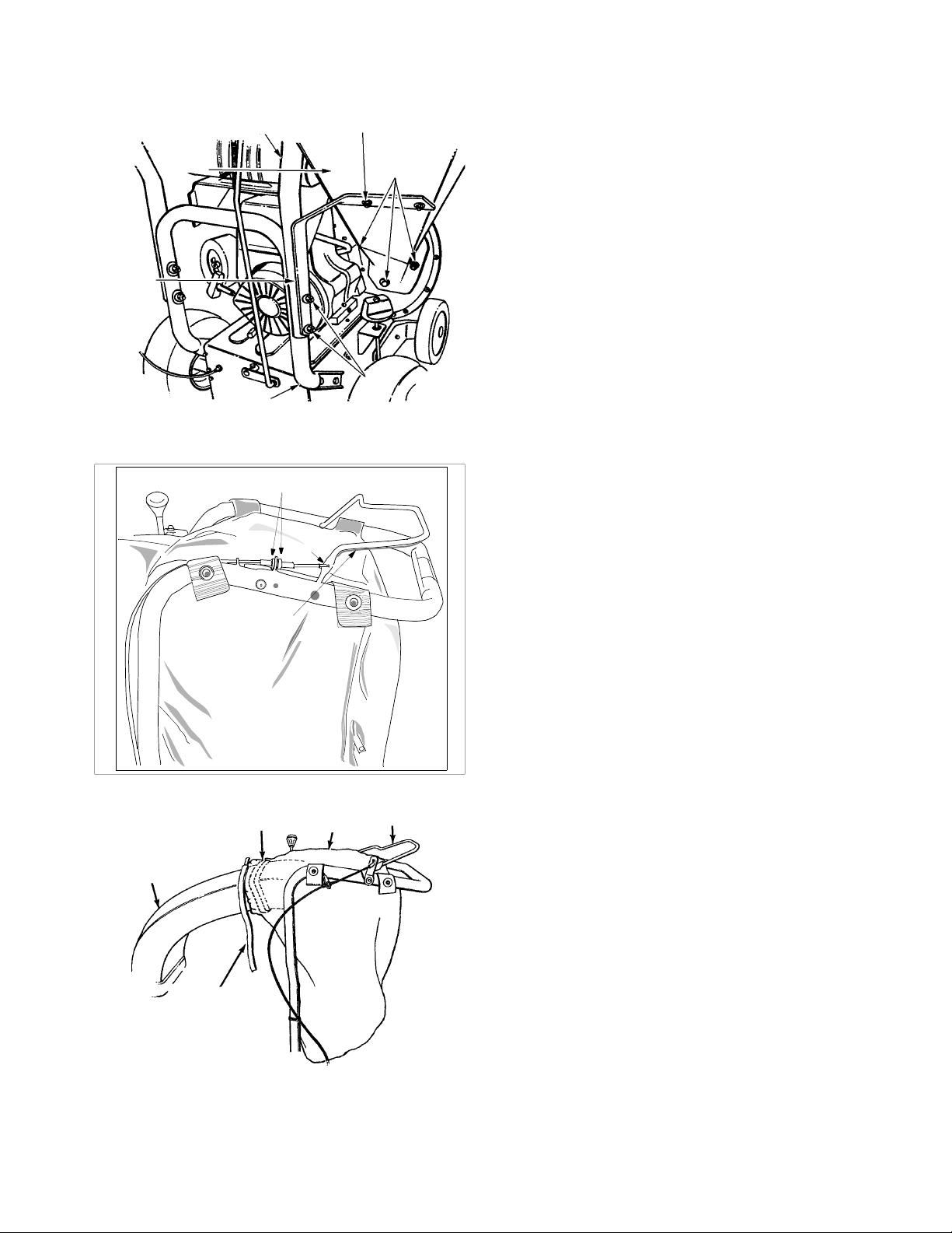
ATTACHING THE CHIPPER CHUTE AND
SUPPORT BRACKET
1. Remove the two hex bo lts , fl at was hers a nd n uts
which are attached to the support bracket.
2. Attach the support brac ket to the bottom of the
chipper chute loosely using the hardware
removed previous ly. Heads of the hex bo lts and
washers go to the inside of the chipper chute.
3. Remove the two hex lock nuts from the hex bolts
which secure the right side of the upper handle to
the lower handle. Leave bolts and washers in
place.
4. Remove three cupped washers and 5/16" hex
nuts from the weld st uds beside the opening o n
the right side of the chipper-vacuum.
5. Place the chipper ch ute in po siti on over the weld
studs (slot goes at the bottom). Secure with
cupped washers and hex nuts just removed.
Only tighten the three nuts one or two threads
for ease of further assembly.
(See Figure 4)
NOTE: Cupped side of the washer goes against
the chipper chute. See Figure 2 to identify cupped
side of washer.
6. Place the support bracket over the two bolts in
the handle. Pushing UP on the chipper chute will
aid the alignment of the holes in the support
bracket with the bolts in the handle.
7. Tighten all hardware securely on the chipper
chute, support bracket and handle.
ATTACHING THE CLUTCH CABLE
The clutch cable has been p artia lly asse mbled at the
factory. You will have to attach the clutch cable, to
the handle.
1. Loosen the hex nuts at the cable bracket and
back the bottom hex nut all the way down.
2. Holding the drive c lutch handle up, hook the “Z”
end of the cable into the drive cl utc h han dle from
the outside to the inside. See Figure 5. Pliers will
aid in assembly.
CLUTCH CABLE ADJUSTMENT
Adjust the hex nuts at the c able bracket so there is
no slack in the cable, but the cable is NOT tight. Do
not overtighten the cable. See Figure 5.
To check the clutch adjustment, proceed as follows.
1. Push the chipper-v acuum ba ckward and fo rward
with the drive clutch handle released. It should
move freely.
2. If it does not, loosen bot h hex nuts at the cable
bracket. See Figure 5. Turn bottom nut
clockwise to loosen the cable.
3. Engage the drive clutch handle (hold against
upper handle), and try to push chipper-vacuum
backward and forward. The wheels should lock
up.
4. If the wheels do not lock up, loosen both hex
nuts at the cable bracket. Turn bottom nut
counterclockwise to tighten the cable.
5. Recheck adjustment. Tighten both hex nuts
when correct adjustment is reached.
Figure 6
7
Page 8
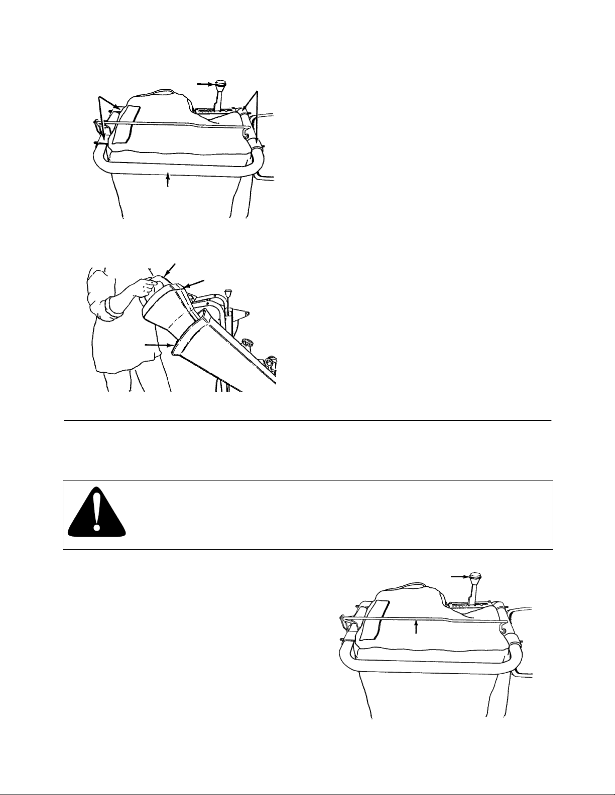
Straps on
Bag
Shift Knob
Straps on
Bag
ATTAC HING THE BAG
1. Place bag inside of handle assembly. Slip the
opening on the bag over the discharge chute,
making certain it is over the rib on the disc harge
chute. See Figure 6.
2. Place the four straps on the top of the bag over
upper handle, hooking them on studs. See
Figure 7. Be sure the bag go es under the drive
clutch handle.
3. Squeeze the clamp on the drawstring, and pull
the drawstring tight. Release the clamp.
Upper Handle
Figure 7
Handle
Tamper Plug
Chipper
Chute
Figure 8
INSTALLING THE SHIFT KNOB
Thread the shift knob onto the end of the shift lever.
TAMPER PLUG (IF EQUIPPED)
The handle on the tamper plug must be in the
vertical positio n as shown in Figure 8. To determine
which side of the tamper plug is up, match the an gle
of the tamper plu g to the angle of the chipp er chute.
Insert the tamper plug into the chipper chute.
NOTE: Tamper plug should remain in the chipper
chute whenever the chipper chute is not in use.
SECTION 6: OPER ATIO N
BEFORE USING YOUR CHIPPER-VACUUM, REFER TO THE ‘‘SAFETY RULES’ ’ AS SHOWN ON PAGES
2 AND 3 OF THIS MANUAL. ALWAYS BE CAREFUL.
The operation of any c hi ppe r-v ac uum ca n r esu lt i n fo re ign obj ects b e ing th ro wn in to th e ey es ,
which can damage your ey es s ev erel y. Al ways w ea r th e sa fet y glas ses p r ovided wi th t his
unit or eye shields before chipping, or while performing any adjustments or repairs.
We recommend Wide Vision Safety Mask for over spectacles or standard glasses.
CONTROLS (See Figure 9)
SHIFT LEVER—The shift lever determines ground
speed of your unit. It may be placed in one of eight
positions. Of these eight, six positions are to go
forward, and two positions are to go in reverse.
Forward—one of six speeds. Position number one
(1) is the slowest. Position number six (6) is the
fastest.
Reverse—two reverse (R) speeds. “R” (all the way
to the right) is the faster of the two.
DRIVE CLUTCH HANDLE
Squeezing the drive clutch handle a gainst the upper
handle engages the wheel drive. Release the drive
clutch handle to stop the wheel drive.
Shift Lever
Drive Clutch Handle
Figure 9
8
Page 9

GAS AND OIL FILL-UP
Service the engine with gasoline and oil as
instructed in the separate engine manual packed
with your chipper-vacuum. Read instructions
carefully.
NOTE: Your chipper -va cu um is s hipped without oil;
however, a small amount of oil m ay be presen t from
the factory. Do not overfill.
WARNING: Never fill fuel tank indoors,
with engine running or whil e engine is hot.
Do not smoke when filling fuel tank.
TO START ENGINE
8. Repeat instructions 6 and 7 until engine fires.
When engine starts, move choke control (if so
equipped) gradually to RUN position.
TO STOP ENGINE
1. To stop engine, move throttle control lever to
OFF position.
2. Disconnect spark plug wire and ground to
prevent accidental starting while equipment is
unattended.
TO EMPTY BAG
Open the large zipper on the bag to empty the bag.
See Figure 10. Be certain the zipper is closed
when operating the unit.
IMPORTANT:
with the clutch handle disengaged, shut engine off
immediately. Readjust as instructed in the “Clutch
Cable Adjustment” section of the Assembly
Instructions.
If unit shows any sign of motion
WARNING: Be sure no one other than
the operator is standi ng near the chippervacuum while star ting or operating . Do not
operate this chipper-vacuum unless the
nozzle, discharge chute and bag have
been properly installed.
NOTE: Your chipper-vacuum unit has a safety
switch at the front of the housing. The nozzle or
optional hose attachment must be in place on the
chipper-vacuum before the engine can be started.
1. Attach spark plug wire to spark plug.
2. Make certain drive clutch handle is in the
disengaged (released ) posit ion .
3. Engines with choke lever: Move choke lever
on engine to CHOKE position. (A warm engine
may not require choking.)
Engines with primer: Prime engine as
instructed in separate engine manual.
4. Move throttle control lever on engine to FAST
position.
5. Place one foot on th e left rear wheel to preven t
the unit from skidding while starting.
6. Grasp starter handle and pull rope out slowly
until engine reaches start of compression cycle
(rope will pull slightly harder at this point). Let
the rope rewind slowly.
NOTE: A noise will be heard wh en finding the star t
of the compression cycle. This noise is caused by
the flails and fingers whi ch are part of the shredd ing
mechanism falling into place, and should be
expected. In addition, the flails and fingers will be
noisy after the engine is started, until the impeller
reaches full speed.
7. Pull rope with a rapid, continuous, full arm
stroke. Keep a firm grip on starter handle. Let
rope rewind slowly. Do not let starter handle
snap back against starter.
Large
Zipper
Closed
Figure 10
TO ENGAGE DRIVE
IMPORTANT: Always release the drive clutch
handle before moving the shift lever.
With the engine running at top speed, move shift
lever into one of the six FORW ARD positions or two
REVERSE positions. Se lect a speed appropriate for
the conditions that ex ist. Use th e slow er sp eeds un til
you are familiar with the operation of the chippervacuum.
To engage the wheel drive, hold the drive clutch
handle against the chipper-vacuum handle.
Releasing the dri ve clutch handle stops the wheels
from driving. Rele ase the dr ive clutc h handle to slow
down when negotiating an obstacle, making a turn or
stopping. Engage slowly to prevent front wheels
from lifting up.
HOW TO USE THE CHIPPER
Do not attempt to shred or chip any material other
than vegetation found in a normal yard (i.e.,
branches, leaves, twigs, etc.). Material such as
stalks or heavy branches up to 3" in dia meter may
be fed into the chipper chute. See Figure 11.
9
Page 10

WARNING: Material up to a
maximum of 3" in diameter may be fed
into the chipper chute. Do not attempt
to shred or chip any material larger
than 3" in diameter. Personal injury or
damage to the machine could result.
Use the tamper plug (if so equipped) to push
material into the chipper chute. See Figure 8.
NEVER PLACE HANDS INSIDE CHIPPER CHUTE.
Place tamper plug inside chipper chute w hen not in
use to deaden the sound.
IMPORTANT: There is a flail screen located
inside the housin g in the discharge area. If the flail
screen becomes clogged, remove and clean as
instructed in the Maintenance section on page 11.
For best performance, it is important to keep the
chipper blades sh arp. Refer to Maintenance section ,
page 11. If the composition of the material being
discharged changes (be comes stringy, etc.) or if the
rate at which the material is di scharged slows down
considerably, it is likely that the chipper blades are
dull and need to be sharpened or replaced.
Figure 11
SECTION 7: ADJUSTMENTS
WARNING: Do not at any time make
any adjustment to the unit without first
stopping engine and disconnecting spark
plug wire.
HEIGHT ADJUSTMENT
The height adjustment knob is located on the right
hand side of the chipper-vacuum. See figure 12.
Turn the knob clockwise to raise the nozzle. Turn the
knob counterclockwise to lower. (Be careful not to
turn knob too far—rod could come out of ferrule.)
The best height for the nozzle will v ary according to
the conditions. Adjust the height of th e nozzle to fin d
the setting which g ives the best p erformance for th e
operating conditio ns. In general, raise the nozzle to
vacuum a thick layer of leaves; lower the nozzle for
smooth surfaces.
Height
Adjustment
Knob
CARBURETOR ADJUSTMENT
WARNING: If any adjustments are
made to the engine while the engine is
running (e.g., carburetor), keep clear of
all moving parts. Be careful of heated
surfaces and muffler.
Minor carburetor adjustment may be required to
compensate for differences in fuel, temperature,
altitude or load. Do not make unnecessary
adjustments. Factory settings are satisfactory for
most applications and conditions. If adjustment is
needed, refer to the s eparate eng ine ma nual p acked
with your chip per-vacuum.
NOTE: A dirty air cleaner will cause engine to run
rough. Be certain air cleaner is clean and attached to
the carburetor before adjusting carburetor.
CLUTCH CABLE ADJUSTMENT
To adjust the clutch cable, refer to the “Clutch Cable
Adjustment” section of Assembly Instructions.
Ferrule
Figure 12
10
Page 11
SHIFT ROD ADJUSTMENT
If the shift rod needs adj ustment to o btain forwar d or
reverse correctly, proceed as follows. See Figure 13.
1. Remove the bag from the unit.
2. Remove the hairpin clip a nd flat wa sher from the
upper end of the sh ift rod. Pull the ferrule o ut of
the hole in the shift lever. (Make certain wave
washer remains in place on the ferrule.)
3. Place the shift lever in 6th position (all the way to
the left).
4. Push down on the shift rod. Thread the ferrule
up or down the shift rod until the ferrule lines up
with the upper hole in the shift lever.
5. Secure ferrule to shift leve r with flat washer and
hairpin clip.
SECTION 8: MAINTENANCE
Shift Lever
6th Position
Hairpin Clip
Flat Washer
Shift Rod
Figure 13
WARNING: Always stop engine and
disconnect spark plug wire before
cleaning, lubricating or performing any
repairs or maintenance.
LUBRICATION
Wheels—Rear wheels are provided with light oil
bearings. Place a fe w drops of SAE 30 oil on each
bearing once a season.
Height Adjustment Mechanism—Lubricate the
pivot points on the height adjustment mechanism
once a season using a light oil.
CLEANING
Clean the chipper-vacuum thoroughly after each
use. Wash the bag per iodically with water. Allow to
dry thoroughly in the shade. Do not use heat.
ENGINE
Refer to the separate engine manual for engine
maintenance instructions.
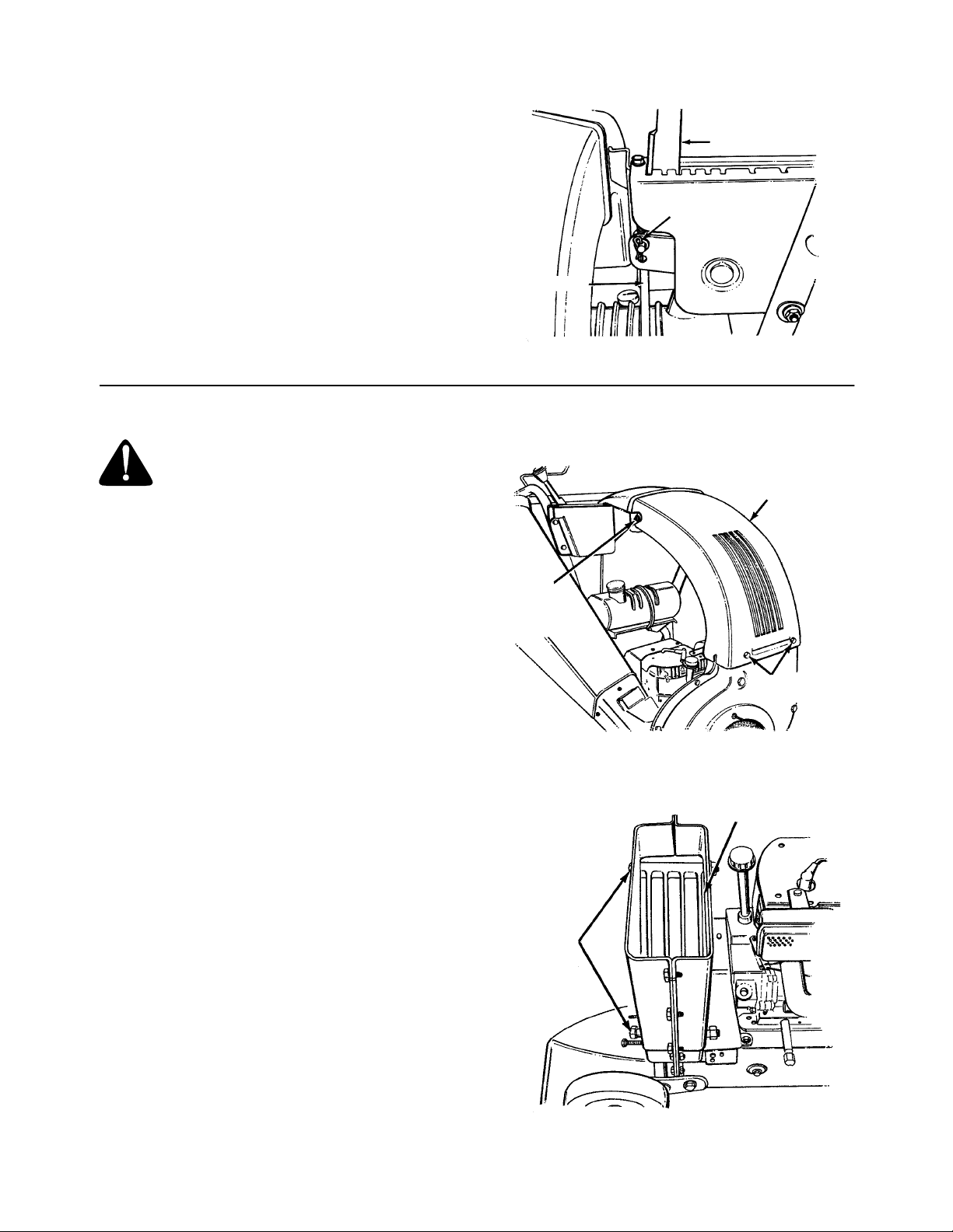
REMOVING THE FLAIL SCREEN
If the discharge area become s clogged, remove the
flail screen and clean area as follows.
1. Stop the engine. Make certain the chippervacuum has come to a complete stop.
Disconnect the spark plug wire before
unclogging the discharge chute.
2. Remove the vacuum bag from the unit.
3. Remove the four self-tapping screws from the
bottom of the discharge chute, and the hex bol t,
flat washer and hex nut from the top. Remove
the discharge chute assembly. See Figure 14.
4. Remove the two hex bolts and hex nuts which
extend through the housin g. Lift the flail screen
from inside the housing. See Figure 15.
5. Clean the screen by scraping or washing with
water. Reinstall the screen.
NOTE: Be certain to reassemble the flail screen
with the curved side down as shown in Figure 15.
Discharge
Chute
Assembly
Hex Bolt
Flat Washer
Hex Nut
Self-Tapping
Screws
Figure 14
Flail Screen
Hex Bolts
and Nuts
Figure 15
11
Page 12

SHARPENING OR REPLACING CHIPPER
BLADES
1. Disconnect the spark plu g wire and move away
from the spark plug.
2. Remove the flail screen as instructed in the
previous section.
3. Remove the plastic belt cov er on the front of the
engine by removing t he two self -tapping scr ews.
See Figure 16.
Belt
Cover
Self-Tapping
Screws
Figure 16
4. Remove the access plate by removing two hex
lock nuts. See Figure 17.
CHANGING THE FRICTION WHEEL
RUBBER
The rubber on the friction wheel is subject to wear
and should be checke d after 50 hours of operation,
and periodically thereafter. Replace friction wheel
rubber if any signs of wear or cracking are found.
1. Drain the gasoline and oil from the chippervacuum.
2. Tip the unit backward so it rests on the handles.
3. Remove the frame cov er by removing eight selftapping screws from underneath the chippervacuum. See Figure 18.
4. Remove the hex shaft from the uni t by removing
the hex bolts, lock washers and flat washers
from each side of the frame. See Figure 19. Hold
the friction wheel assembly, and slide the hex
shaft out of the unit toward the right side.
5. Remove the six screws from the friction wheel
assembly (three from each side). Remove the
friction wheel rubber from between the friction
wheel plate.
6. Reassemble new friction wheel rubber to the
friction wheel assembly, tightening the six
screws in rotation and with equal force.
7. Slide the friction wheel assembly up onto the
shift mechanism, then slide the hex shaft back
into the unit. Reassemble in reverse order.
8. Readjust the clutch cable. Refer to adjustment
section.
Hex
Lock Nuts
Access
Plate
Figure 17
5. Locate one of the chipper blade s in the access
plate opening by rot ating the impeller assembly
by hand. Remove the blad e using a 3/16" allen
wrench on the outside of the blade and 1/2"
wrench on the impeller assembly, inside the
housing. Torque hardware to 250-300 inch
pounds.
6. Remove the other blade in the same manner.
Replace or sharpen blades. If s harpening, make
certain to remove an equal amount from each
blade. Reassemble in reverse order.
NOTE: Make certain blades are r eassembled with
the sharp edge facing upward, as viewed from the
access plate opening.
Friction
Wheel
Self-Tapping
Screws
Frame Cover
Figure 18
Hex
Shaft
Figure 19
Hex Bolt
Lock Washer
Flat Washer
12
Page 13
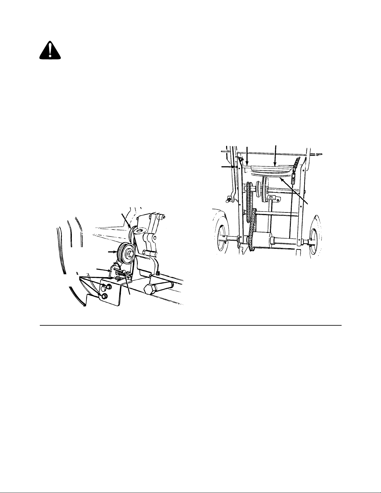
BELT REMOVAL AND REPLACEMENT
WARNING:
wire and move away from the spark
plug.
1. Remove the plastic belt cov er on the front of the
engine by removing two self-tapping screws.
Refer to Figure 16.
2. Drain the gasoline and oil from the chippervacuum.
3. Tip the unit backward so that it rests on the
handles.
4. Remove the frame cov er by removing eight selftapping screws from underneath the chippervacuum. Refer to Figure 18.
5. Remove the idler pulley br acket as follows. ( See
Figure 20.)
a. Take the tension off the belt by pivoting the
idler pulley towar d you, and li ne up the holes
in the idler bracket asse mbly. Insert a nail or
similar object through the holes to hold the
idler pulley in this position.
b. Remove three self-tappi ng screws , and lift off
the idler bracket assembly.
Disconnect the spark plug
Engine
Pulley
6. Remove the hex bolt and lock washe r from the
engine pulley. See Figure 20. Slip the engine
pulley off the engine shaf t, and remove the belt
from the pulley.
7. Loosen the nut on the stop bolt until there is
clearance between the sup port bracket and the
friction wheel disc. See Figure 21.
8. Slip the belt between the friction wheel and
friction wheel disc. Remove and replace belt.
Reassemble following instruction in reverse
order.
NOTE: The support bracket must rest on the stop
bolt after the new belt has been assembled.
Support
Stop Bolt
Loosen
Nut
Bracket
Friction
Wheel Disc
Idler
Pulley
Idler
Bracket
Assembly
Self-Tapping
Screws
Nail
Figure 20
SECTION 9: OFF-SEASON STORAGE
The following steps s hould be taken to prepare your
chipper-vacuum for storage .
1. Remove all dirt from exterior of engine and
equipment.
2. Refer to engine manual for correct engine
storage instructions.
3. Wipe unit with an oiled rag to preve nt rust (us e a
light oil or silicone), especially if storing in an
unventilated or metal storage shed.
4. Store in a dry, clean a rea. Do not store next to
corrosive materials, such as fertilizer.
Figure 21
13
Page 14

SECTION 10: TROUBLE SHOOTING GUIDE
T rouble Possible Cause(s) Corrective Action
Engine fails to start Dirty aircleaner.
Fuel tank empty or stale fuel.
Spark plug wire
disconnected.
Cannot pull recoil cord.
Choke not in ON position.
Faulty spark plug.
Nozzle safety switch not
depressed.
Loss of power; operation
erratic
Engine overheats Carburetor not adjusted
Too much vibration Loose parts or damaged
Unit does not discharge Discharge chute clogged.
Rate of discharge slows
considerably or
composition of discharged
material changes
Spark plug wire loose.
Unit running on CHOKE.
Blocked f uel line or stale fuel.
Water or dirt in fuel system.
Carburetor out of adjustment.
Low engine RPM.
Dirty air cleaner.
properly.
Dirty aircleaner.
Engine oil level low.
impeller.
Foreign object lodged in
impeller.
Low engine RPM.
Vacuum bag is full.
Low engine RPM.
Chipper blades dull.
Refer to the engine manual packed with your unit.
Fill tank with clean, fresh gasoline. Fuel will not last over
thirty days unless a fuel stabilizer is added.
Connect wire to spark plug.
Obstruction lodged in impeller. Stop immediately and disconnect spark plug wire. Re move lodged object.
Move switch to ON position.
Clean, adjust gap or replace.
Adjust metal tab so it depresses the safety switch.
Connect and tighten spark plug wire.
Move choke lever to OFF position.
Clean fuel line; fill tank with clean fresh gasoline. Fuel will
not last over thirty days unless a fuel stabilizer is used.
Disconnect fuel line at carburetor to drain fuel tank. Refill
with fresh fuel.
Refer to the engine manual packed with your unit.
Always run engine at full throttle.
Refer to the engine manual packed with your unit.
Refer to the engine manual packed with your unit.
Refer to the engine manual packed with your unit.
Fill crankcase with proper oil.
Stop engine immediately and disconnect spark plug wire.
Have unit serviced by a an authorized service dealer.
Stop engine immediately and disconnect spark plug wire.
Clean flail screen and inside of blower housing. See
Maintenance section of this manual.
Stop engine immediately and disconnect spark plug wire.
Remove lodged object.
Always run engine at full throttle.
Empty bag.
Always run engine at full throttle.
Replace chipper bl ades or see your authorized service
dealer.
Note: For repairs beyond the minor adjustments above, contact your local authorized service dealer.
14
Page 15
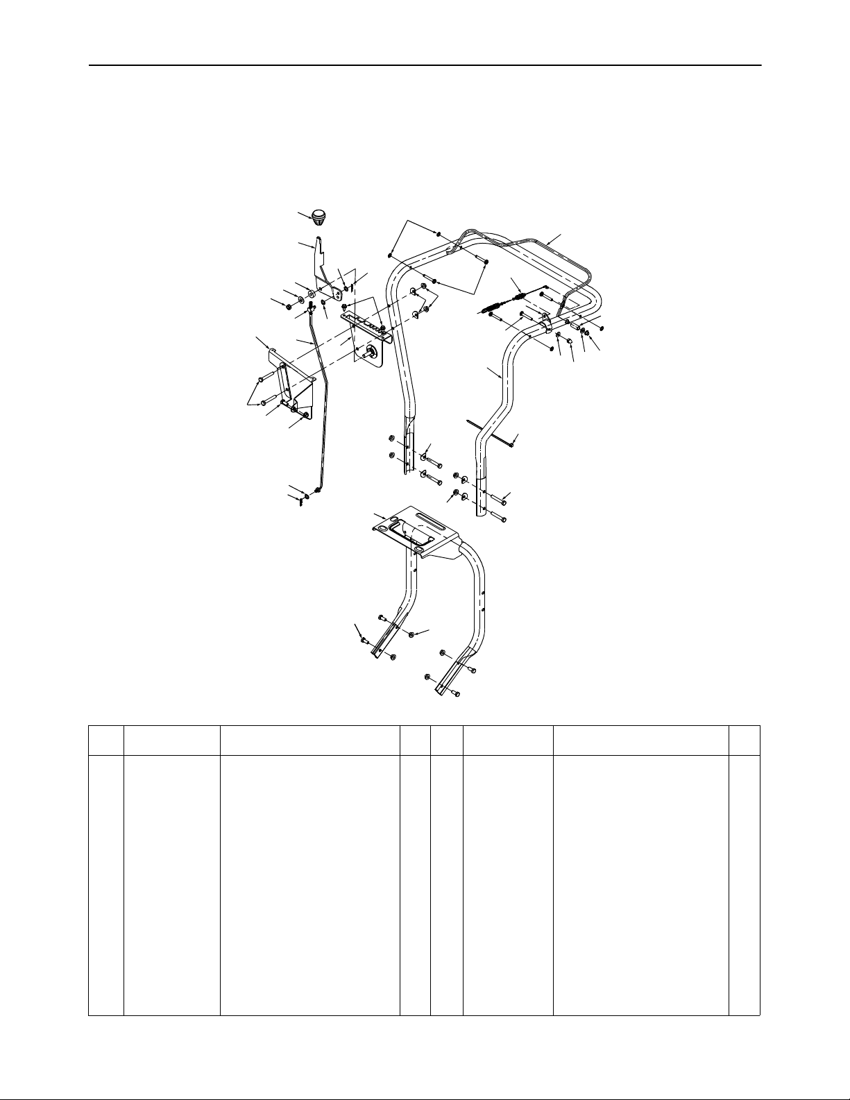
SECTION 11: ILLUSTRATED PARTS
CSV 260
14
27
17
16
18
11
9
26
6
8
12
13
19
25
19
5
1
2
13
7
4
12
20
20
12
24
10
28
21
3
6
29
15
22
23
31
30
8
REF.
PART
NO.
NUMBER DESCRIPTION QTY
1 1539-019 Nut, Push, .25 4 18 736-0300
12
REF.
PART
NO.
NUMBER DESCRIPTION QTY
Washer, Flat, .406 x .875x
.059
2 747-1133-0498 Control Assembly, Clutch 1 19 736-0413 Washer, Spring, .390 x .62 2
3 749-1083-0498 Handle Assembly, Upper 1 20 736-0451 Washer, Saddle, .320 x .93 6
4 649-0012-0498 Handle Assembly, Lower 1 21 710-0495 Carr. Bolt 1/4-20 x 1.75” Lg. 1
5 681-0076-0498 Bracket Assembly, Shift 1 22 750-1185 Spacer 1
6 710-3103 Screw, Hex Cap, 5/16-18 x 2.0 6 23 726-0135 Nut, Cap Speed 1
7 710-0896 Screw,Hex Wash Hd,4-14x 2 24 746-1080 Cable, Clutch 1
8 710-3008 Screw, Hex Cap 5/16-18 x .75 5 25 747-0626 Rod, Shift 1
9 711-0677 Ferrule 1 26 781-0626-0498 Cover, Shift 1
10 711-0737 Pin, Stud, .250 x 1.75 4 27 784-0297A Handle, Shift 1
11 712-0116 Nut, Hx Ins Jam Lk 3/8-24 Thd. 1 28 781-0157 Bracket, Cable Mtg. 1
12 712-3004A Nut, Hex Flange Lock 5/16-18 11 29 736-3020 Washet, Flat .271 x .63 x .65 1
13 714-0104 Pin, Internal Cotter 2 30 712-0442 Nut, Lock, Acorn 1/4-20 1
14 720-0232 Knob, Shift 1 31 736-0275 Washer, Flat 5/16 1
15 725-0157 Cable Tie 1
16 735-0126 Rubber Washer 1
17 736-0117 Washer, Flat .385 x .62 x .6 1
1
15
Page 16
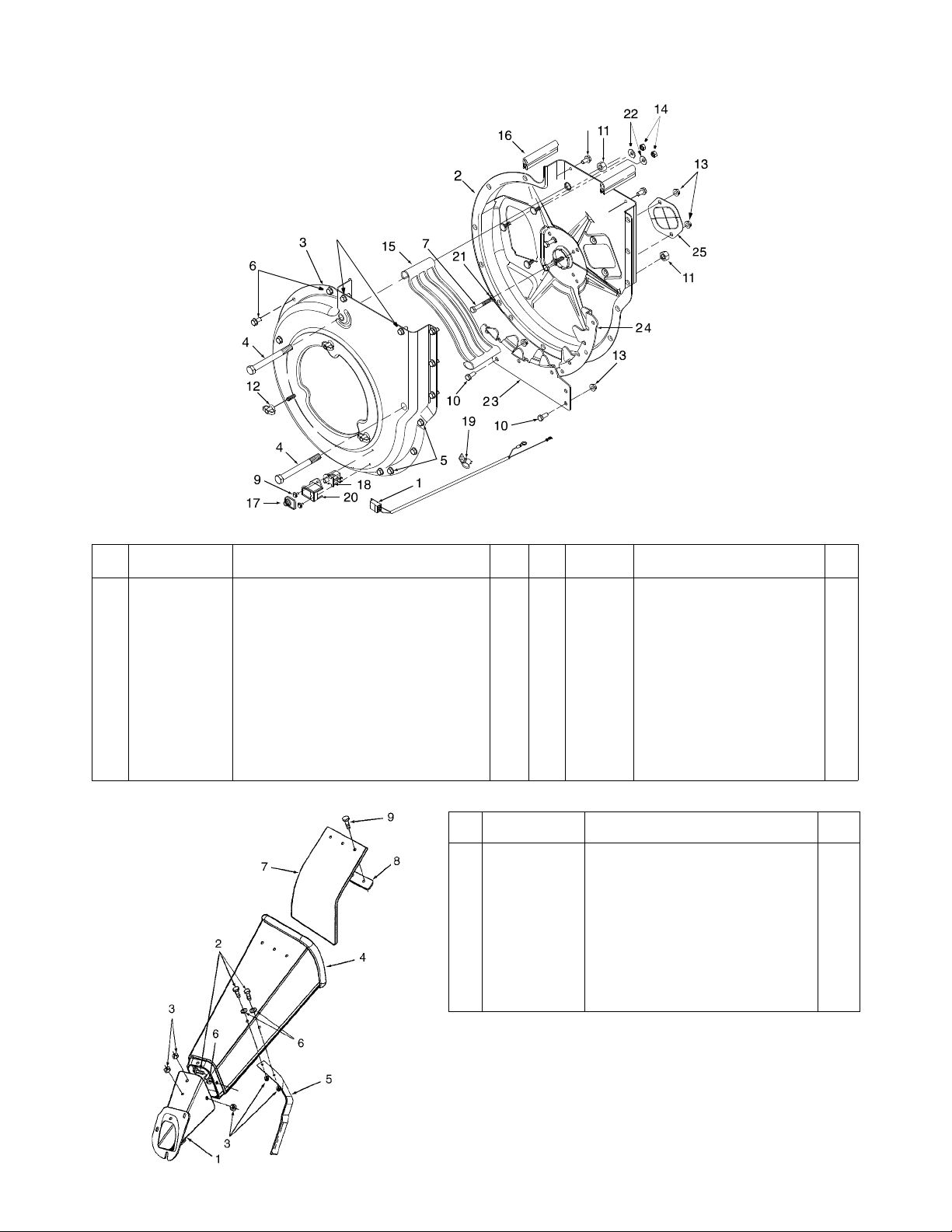
CSV 260
5
5
REF.
PART
NO.
NUMBER DESCRIPTION QTY.
1 629-0241 Harness, Wire 1 14 712-3010 Nut, Hex, 5/16-18 3
2 681-0059-0498 Housing Ass’y, Inner Flail 1 15 719-0326 Screen, Discharge 1
3 681-0060-0498 Housing Ass’y, Outer Flail 1 16 723-0438 Rubber Seal 2
4 710-0382 Screw, Hex Cap, 1/2-13 x 5.0 2 17 725-1700 Cover, Switch 1
5 710-0604 Screw, Hex Wash Hd Tapp 5/16-18 x .62 10 18 725-3166 Switch, Snap Mount 1
6 710-0607 Screw, Hex Wash Hd Tapp 5/16-18 x .50 8 19 726-0272 Clamp 1
7 710-0772 Screw, Hex Cap, 5/16-24 x 2 GR5 3 20 731-1613 Cover, Safety Switch Mtg. 1
9 710-1268 Screw, Hex Wash Hd Tapp #10-16 x .38 21 736-0119 Washer, Lock, 5/16 3
10 710-3008 Screw, Hex Cap, 5/16-18 x .75 GR5 2 22 736-0242 Washer, Bell, .345 x .88 x .06 3
11 712-0384 Nut, Hex Center Lock, 1/2-13 2 23 781-0598 Blade, Lower Shredder 1
12 712-0421 Knob, 5/16-18 2 24 781-0599 Blade, Upper Shredder 1
13 712-3004A Nut, Hex Flange Lock, 5/16-18 3 25 781-0627 Cover, Chipper Blade 1
REF.
NO.
1 681-0068-0498 Chute Assembly, Chipper 1
2 710-0751 Screw, Hex Cap, 1/4-20 x .625 5
3 712-3027 Nut, Hex Flange Lock, 1/4-20 5
4 731-1574 Chute, Chipper 1
5 781-0625-0498 Bracket, Chipper Chute Support 1
6 736-0173 Washer, Flat, .28 x .74 x .63 5
7 735-0249 Flap, Chipper Chute 1
8 781-0633 Strip, Chute Flap 1
9 728-0175 Rivet, Pop, .156 x .504 3
— 731-1617 Tamper Plug (Optional - Not Shown) 1
REF.
PART
NO.
NUMBER DESCRIPTION QTY
PART
NUMBER DESCRIPTION QTY.
16
Page 17
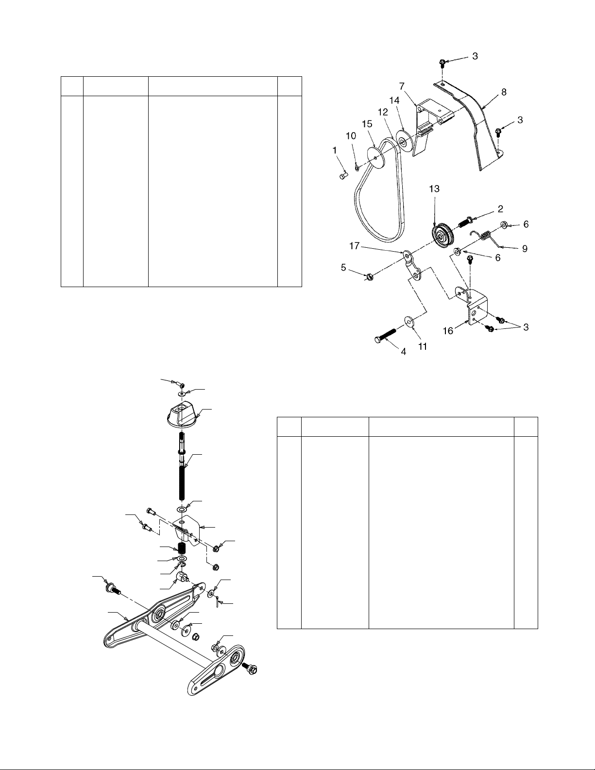
CSV 260
REF.
PART
NO.
NUMBER DESCRIPTION QTY.
1 710-0230 Screw, Hex Cap, 1/4-28 x .50 1
2 710-0723 Screw, Hex Cap, 3/8-16 x 1 .25 1
3 710-08 96 Screw, Hex Wash Hd Tapp. 1/4-
4 710-0646 Screw, Hex Cap, 5/16-18 x 2.0 1
5 712-0266 Nut, Hex Cent-L Jam, 3/8-16 1
6 712-3004A Nut, Hex Flange Lock, 5/16-18 2
7 719-0330A Adapter, Engine Mt g 1
8 731-1584 Belt Cover 1
9 732-07 45 Spring, Torsion, .54 x 1.0 1
10 736-0329 Washer, Lock, 1/4 1
11 748-0234 Shoulder Spacer, .50 ID x .27 Lg 1
12 754-0256 V-Belt, 3/8 x 29.0 Lg 1
13 756-0313 Pulley, Flat Idler 1
14 756-0987 Pulley Half, 2.0 Dia 1
15 756-0986 Pulley Half, 2.0 Dia 1
16 781-0611-0498 Bracket, Idler Pivot 1
17 781-0614 Bracket, Idler 1
14 x .625
5
16
3
13
10
REF.
PART
NO.
NUMBER DESCRIPTION QTY.
1 681-0096-0498 B racket Ass’y, Wheel Pivot 1
17
15
4
19
11
15
9
5
1
18
12
7
14
8
6
3 710-0924 Screw, Pan Hd Mach, 1/4-20 x .75 1
4 710-3008 Screw, Hex Cap, 5/16-18 x .75 GR5 2
5 711-1041 Ferrule, Adjustment 1
6 712-0431 Nut, Hex Flange Lock, 3/8-16 2
7 712-3004A Nut, Hex Flange Lock, 5/16-18 2
8 714-0115 Pin, Cotter, 1/8 x 1.0 1
9 716-0104 E-Ring, .50 Dia 1
10 720-0236 Knob 1
11 732-0645 Spring, Compression 1
12 736-0247 Washer, Flat, .406 x 1-1/4 2
13 736-0270 Washer, Bell, .265 x .75 x .062 1
14 736-0300 Washer, Flat, .406 x .875 x .059 1
15 736-0369 Washer, Flat, . 508 x 1.0 x .020 2
16 738-0955 Shoulder Bolt, .75 x .43: 3/8-16 2
17 747-0631 Rod, Height Adj ustment 1
18 711-0242 Spacer, .380 ID x 1.0 OD x .32 Lg 1
19 781-0605-0498 Bracket, Height Adj 1
17
Page 18
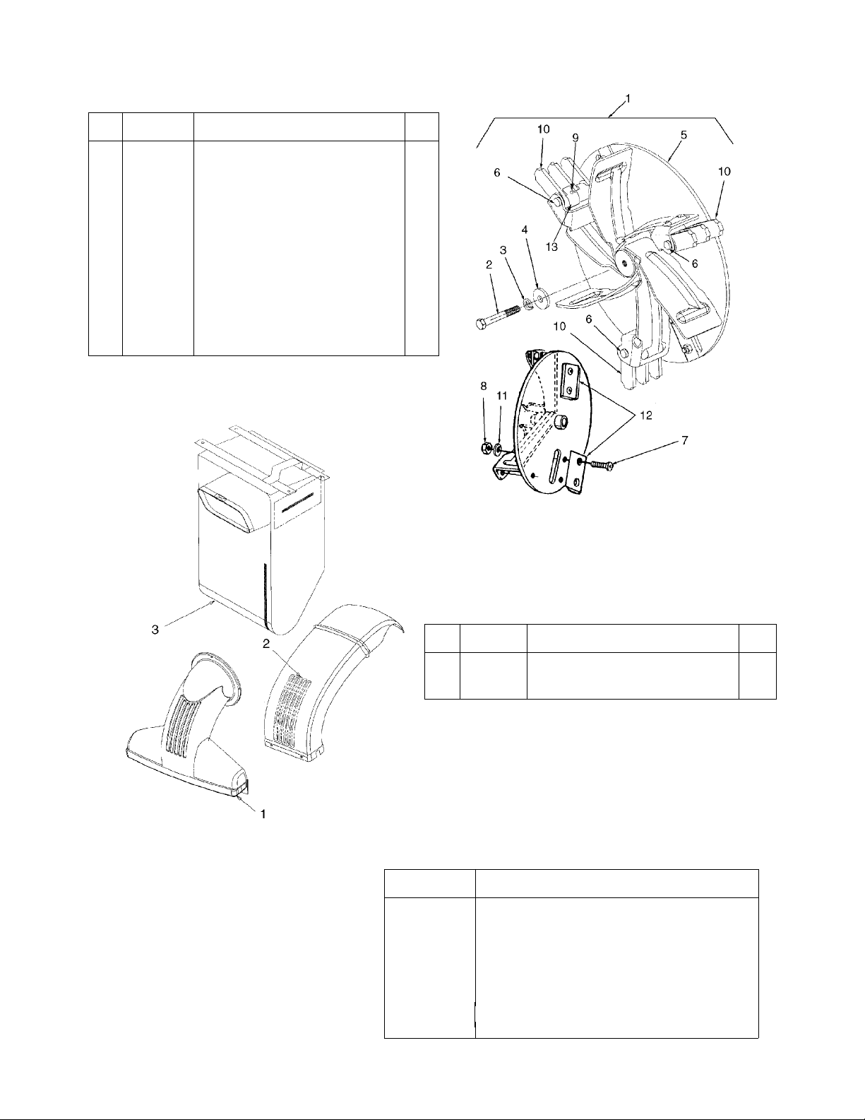
CSV 260
REF.
PART
NO.
NUMBER DESCRIPTION QTY.
1 681-0078 Impeller Ass’y, Complete Includes
2 710-1273 Screw, Hex Cap, 3/8-24 x 2.75 GR5 1
3 736-0217 Washer, Lock, 3/8 Heavy Duty 1 1
4 736-0247 Washer, Flat, .406 x 1-1/4 HD1 1
5 681-0052 Impeller Assembly 1
6 711-0833B Pin, Clevis 3
7 710-1054 Screw, Flat Hd. Cap, 5/16-24 x 1.0 4
8 712-0411 Nut, Hex Insert Lock, 5/16-24 4
9 715-0166 Pin, Spirol, 5/32 x 1.125 3
10 719-0329 Blade, Flail 3
11 736-0119 Washer, Lock, 5/16 4
12 742-0544 Blade, Chipper 2
13 781-0735 Pin Retaining Clip 3
Ref. Nos. 5 thru 13
1
REF.
PART
NO.
NUMBER DESCRIPTION QTY.
1 631-0029 Nozzle Assembly, Vacuum 1
2 731-1616 Chute, Discharge 1
3 764-0474 Bag, Vacuum 1
Labels found on your unit.
PART
NUMBER DESCRIPTION
777S30181 Label—Danger Top of Chipper Chute
777I20350 Label—Squeeze Bail
777I20351 Label—Raise, Lower
777S30183 Label—Warning Top Flail Housing
777S30041 Label—Warning Back Flail Housing
777I20353 Label—6 Speed
777D00543 Label—Hubcaps
777D03044 Label—CSV 260
777D03045 Label—9 HP Cub Cadet
18
Page 19

CSV 260
REF.
PART
NO.
NUMBER DESCRIPTION QTY.
1 618-0168 Differential Ass’y Complete 1
2 710-1206 Screw, Hex Wash Hd Tapp 1/4-20
3 711-1035 Cross Shaft 1
4 711-1037 Axle Shaft, .75 x 10.95 1
5 711-1038 Axle Shaft, .75 x 9.82 1
6 713-0445 Spocket, 22T 1
7 716-0232 Ring, Retaining 4
8 717-1358 Gear, Differential, 14T 2
9 717-1437 Gear, Differential, 10T 2
10 719-0333 Housing, Differential RH 1
11 719-0334 Housing, Differential LH 1
12 748-0383 Bearing, Flange, .75 ID x 1.0 OD 2
13 737-0300 Grease, Benalene 1 oz
14 721-0328 Sealant, Ultra Grey Loctite 5699 1
x 2-5/16
4
REF.
PART
NO.
NUMBER DESCRIPTION QTY.
1 710-0751 Screw, Hex Cap, 1/4-20 x .62 2
2 712-3027 Nut, Hex Flange Lock, 1/4-20 2
3 726-0209 Cable Tie, 30.66 Lg 1
4 726-0205 Clamp, Hose, 1/2 Inch 2
5 73 6 -0173 Washer, Flat, .28 x .74 x .063 2
6 751-0535 Hose, Fuel Line 9 Inch 9 In.
7 751-0603 Cap, Fuel 1
8 751-0610 Tank, Fuel 1
19
Page 20
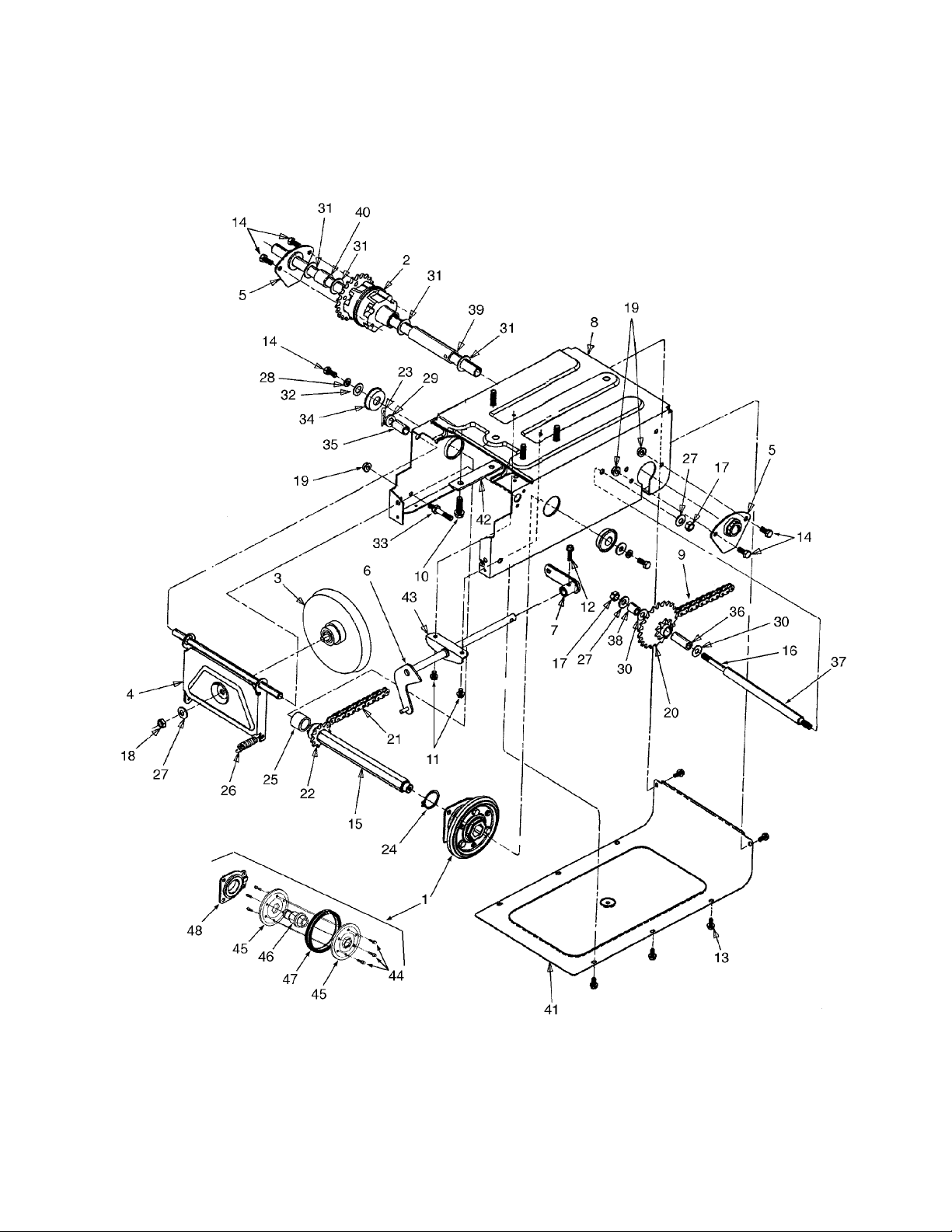
CSV 260
20
Page 21
CSV 260
REF.
PART
NO.
NUMBER DESCRIPTION QTY.
1 684-0042B Friction Wheel Ass’y Complete 1 25 750-0998 Spacer, .675 x 1.0 x 1.53 1
2 618- 0168 Differential Ass’y Complete 1 26 732-0209 Spring, Extension 2
3 656-0012A Friction Disc Assembly 1 27 736-0105 Washer, Bell, .406 x .870 x .063 3
4 681-0055 Bracket Ass’y, Frctn Wheel Supt 1 28 736-0119 Washer, Lock, 5/16 2
5 681-0058 Bracket Ass’y, Axle 2 29 736-0160 Washer, Flat, .536 x .930 x .05 1
6 681- 0082 Shaft Ass’y, Shift 1 30 736-0267 Washer, Flat, .385 x .87 x .06 2
7 681-0072 Arm Ass’y, Shift 1 31 736-0287 Washer, Flat, .793 x 1.24 x .06 4
8 681-0081-0498 Frame Assembly 1 32 736-3089 Washer, Flat, .345 x 1.0 x .100 2
9 713-0374 Chain, #420 x 36 Lnks 1 33 738-0908 Bolt, Idler 1
10 710-0502A Screw, Hex Wash Hd Tapp 3/8-16
11 710-0653 Screw, Hex Was h Hd Tapp 1/4-20
12 710-0788 Screw, Hex Was h Hd Tapp 1/4-20
13 710-0896 Screw, Hex Was h Hd Tapp 1/4-14
14 710-3008 Screw, Hex Cap, 5/16-18 x .75
15 711-1073 Hex Shaft 1 39 750-0980 Spacer, .782 x 1.0 x 4.11 1
16 711-1028 Jack Shaft 1 40 750-0981 Spacer, .782 x 1.0 x .99 1
17 712-0241 Nut, Hex, 3/8-24 2 41 781-0612A-0498 Cov er, Frame Bottom 1
18 712-0711 Nut, Hex Jam, 3/8-2 4 1 42 781-0 638 A Plate, Frame Reinforcement 2
19 712-3004A Nut, Hex Flange Lock, 5/16-18
20 713-0330 Sprocket Ass’y, 9T & 22T 1 44 710-0599 Screw, Hex Wash Hd Tapp 1/4- 20 6
21 713-0284 Chain, #41 x 36 Lnks 1 45 784-5617A Plate, Friction Wheel 2
22 713-0413 Sprocket, 10T 1 46 718-0301A Hub, Friction Wheel 1
23 714-0111 Pin, Cotter, 3/32 x 1.0 1 47 735-0243 Wheel, Rubber Friction 1
24 716-0102 Ring, Snap, 1.0 Dia 1 48 618-0063 Bearing Ass’y, Friction Wheel 1
x 1.25
x .375
x 1.0
x .625
GR5
GR5
REF.
PART
NO.
NUMBER DESCRIPTION QTY.
4 34 741-0563 Bearing, Ball 2
2 35 748-0382 Spacer, .508 x .75 x .94 1
1 36 750-0351 Sleeve, .380 x .623 x 1.5 1
8 37 750-0978 Spacer, .407 x .625 x 7.86 1
6 38 750-0979 Spacer, .407 x .625 x .71 1
5 43 784-5590-0498 Bracket, Frame Shift 1
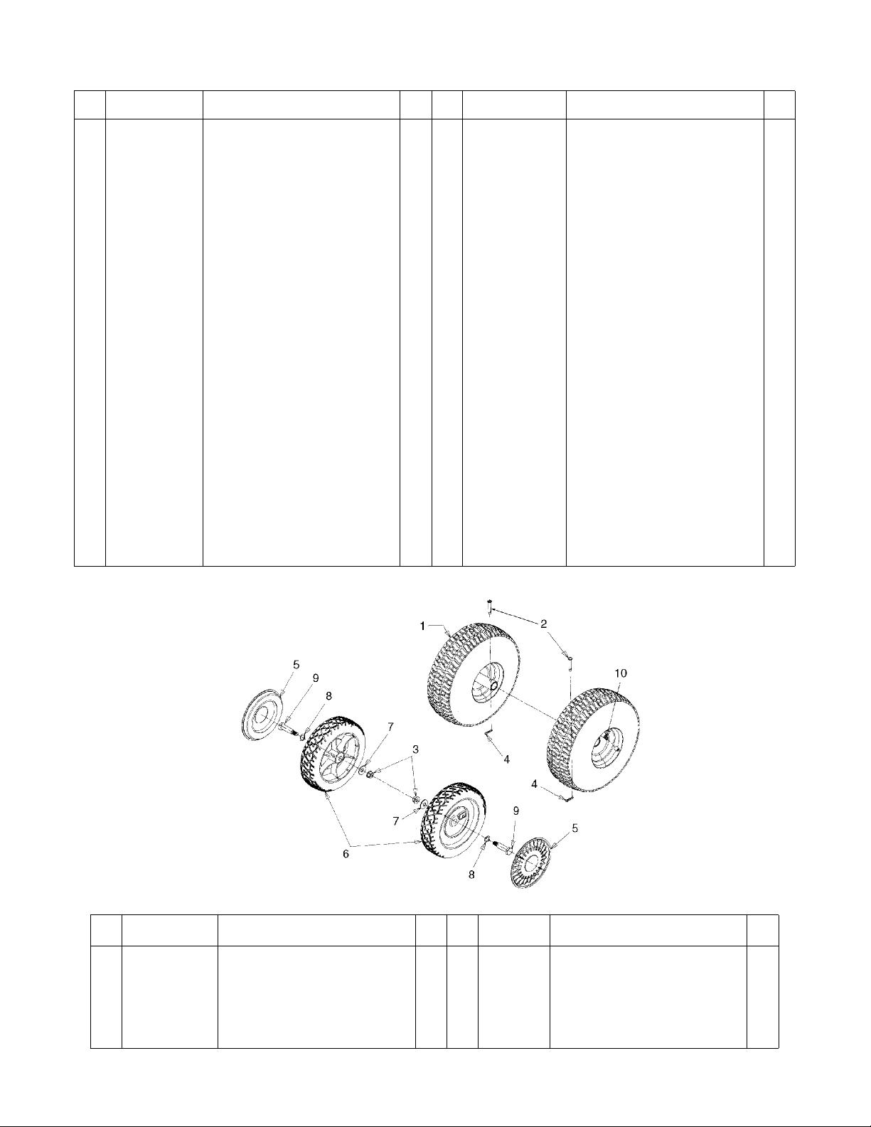
REF.
PART
NO.
NUMBER DESCRIPTION QTY.
1 634-0100
634-0101-0499
734-1598
2 711-1017 Pin, Clevis, .25 x 1.53 2 7 736-0105 Washer, Bell, .401 x .870 x .06 2
3 712-0431 Nut, Hex Flange Lock, 3/8-16 2 8 736-0232 Washer, Wave, .53 x .78 x .013 2
4 714-0104 Pin, Internal Cotter 2 9 738-0213 Shoulder Bolt 2
5 731-0982A Hubcap, Beige 2 10 734-0255 Valve, Tubeless Air 2
Wheel Ass’y Complete
Rim Assembly
Tire, Pneumatic, 10 x 4
REF.
PART
NO.
NUMBER DESCRIPTION QTY.
2
6 734-1517B Wheel Ass’y Complete, 8 x 2.0 2
2
2
21
Page 22

Notes
Page 23

Notes
Page 24

MANUFACTURER’S LIMITED WARRANTY FOR:
TWO-YEAR RESIDENTIAL
ONE-YEAR COMMERCIAL
Proper maintenance of your Cub Cad et equi pm ent is the own er’s responsibility. Follow the instructions in your
operator’s manual for correct lubricants and maintenance schedule. Your Cub Cadet dealer carries a
complete line of quality lubricants and filters for your equipment’s engine, transmission, chassis and
attachments.
Riding mowers, lawn tractors, garden tractors, Cub Cadet
attachments and home maintenance products
This limited warra nty for residential users, covers a ny defect in mater ials or workmansh ip in your Cub Cadet
equipment for two years from the dat e of purchase for the firs t user purchase r. We will replace or repa ir any
part or parts without charge through your authorized Cub Cadet dealer.
Batteries have a one-year prorated limited warranty with 100% replacement during the first three months.
V-belts for either the traction drive or any attachments are covered for one year only.
Cub Cadet equipment used commercially is warranted for one year only.
(Commercial use is defined as either having hired operators or used for income producing purposes.)
Items not covered
The warranty doe s not c over rout ine ma intena nce i tems suc h as lubri cants, f ilt ers (o il, fue l, air a nd h ydraul ic),
cleaning, tune-ups, br ake and/or clutch inspection, a djustments made as part of normal maintenance, blade
sharpening, set-up, a bus e, a ccid ent s and normal wear. It doe s n ot c ov er incidental costs s uch as tr ansporting
your equipment to and from the dealer, telephone charges or renting a product temporarily to replace a
warranted product.
There is no other express warranty.
How to obtain service
Contact your autho riz ed Cub Ca det s ervi cing de ale r who s old you your Cub Ca det eq uip men t. I f this dealer is
not available, see the Consumer Yellow Pages under “lawn mowers” for the name of a dealer near you.
If you need further assistance in finding an authorized Cub Cadet servicing dealer, contact:
Cub Cadet Corporation
Post Office Box 368023
Cleveland, Ohio 44136
How does state law apply?
This limited warranty gi ves y ou spec ific lega l rig hts, and you m ay als o have ot her right s which va ry from s tate
to state.
 Loading...