

Page 1

Service Manual
CC-949 Self Propelled Lawn Mower
NOTE: These materials are for use by trained technicians who are experienced in the service and repair of outd oor power
equipment of the kind described in this publication, and are not intended for use by untrained or inexperienced individuals.
These materials are intended to provide supplemental information to assist the trained technician. Untrained or inexperienced individuals should seek the assistance of an experienced and trained professional. Read, understand, and follow all
instructions and use common sense when working on power equipment. This includes the contents of the product’s Operators Manual, supplied with the equipment. No liability can be accepted for any inaccuracies or omission in this publication,
although care has been taken to make it as complete and accura te as possible at the time of publication. However, du e to
the variety of outdoor power equipment and continuing product changes that occur over time, updates will be made to these
instructions from time to time. Therefore, it may be necessary to obtain the latest materials before servicing or repairing a
product. The company reserves the right to make changes at any time to this publication without prior notice and without
incurring an obligation to make such changes to previously published versions. Instructions, photographs and illustrations
used in this publication are for reference use only and may not depict actual model and component parts.
© Copyright 2006 MTD Products Inc. All Rights Reserved
MTD Products Inc. - Product Training and Education Department
FORM NUMBER - 769-02121
4/2006
Page 2

Page 3

Table of Contents
1. INTRODUCTION ........................................................................................................................1
2. BLADE REMOVAL .....................................................................................................................1
3. BELT REMOVAL .......................................................................................................................2
4. TRANSMISSION AND CHAIN CASE REMOVAL .....................................................................4
5. ENGINE CONTROL CABLE ................................ ......................................................................6
6. TRACTION CONTROL CABLE .. ... ... ... .... ... ... ... ... .... ... ... ... .... ... ... .......................................... ... ..7
7. FRONT AXLE..............................................................................................................................9
1
Page 4

2
Page 5

CC-949 Rear Wheel Drive
Self-Propelled Mower
CC-949 Rear Wheel Drive
1. INTRODUCTION
1.1. Disclaimer: This service manual is intended to
be used by trained technicians.
1.2. Disclaimer: The information contained in this
manual is current and accurate at the time of
writing, but is subject to change without notice.
1.3. Description: The CC-949 is a multi-function
rear wheel drive self propelled mower. It can
bag, mulch or side discharge depending on
which chute or plug is attached to the mower.
See Figure 1.3.
2. BLADE REMOVAL
2.1. Disconnect and ground the spark plug wire.
2.2. Take measur es to prevent fuel from leaking from
the gas tank.
2.3. Lock the blade in place by using a piece of 2” x
4” or a blade locking tool. See Figure 2.3.
Blade locking tool
Figure 2.3
Figure 1.3
CAUTION: When ever working near the blades
of this or any lawn mower it is very important to
disconnect and ground the spark plug wire. Also,
if the unit needs to be tipped over make sure to
take measures to prevent fuel from leaking from
the gas tank.
2.4. Remove the blade retaining bolt using a 5/8”
wrench.
2.5. Inspect the blade adapter and the bla de supp or t
(the metal strip under the blade ret aining bolt) for
wear or damage.
CAUTION: If the pins or the star on either piece
are worn or damaged they must be replaced.
Failure to due so can result in the blade coming
off.
2.6. Install new or sharpened and balanced blade in
the reverse order, ensuring that the pins on the
blade support match with the pins on the blade
adapter.
NOTE: Blade should be tightened to 37.5 to 50
ft. lbs(51 to 68 Nm) of torque.
CAUTION: Blades must be balanced before
installing them on a mower. Failure to due so
can result in a heavy vibration in the mower .
2.7. Run the mower before returning it to service.
1
Page 6

Self-Propelled Mower
3. BELT REMOVAL
3.1. Disconnect and ground the spark plug.
3.2. Take measur es to prevent fuel from leaking from
the gas tank.
3.3. Remove the blade as described in the blade
removal section.
3.4. Remove the blade adapter and washers, making
sure to note the order and orientation of the
washers. See Figure 3.4.
Wave washer
Flat washers
3.6. Remove the three screws holding the shroud in
place using a 3/8” wrench. See Figure 3.6.
Three shroud screws
Figure 3.6
3.7. Remove the hub caps on the rea r wheels by pr ying them off. See Figure 3.7.
Figure 3.4
3.5. Remove the bottom pulley half. See Figure 3.5.
Bottom pulley
half
Figure 3.5
Figure 3.7
2
Page 7

Self-Propelled Mower
3.8. Remove the left rear wheel by removing the hex
head bolt in the center of the wheel with a 7/16”
wrench. Then take the right wheel off.
NOTE: You may have to hold the left axle half to
get the right wheel off. Y ou can do this with a pair
of vise grips. Care should be taken not to damage the splines on the end of the axle.
See Figure 3.8.
Figure 3.8
3.10. Loosen the bolt that goes through the idler bearing using two 7/16” wrenches. Unlatch the metal
tab holding the belt to the bearing.
See Figure 3.10.
Unlatch tab
Loosen bolt
Figure 3.10
3.11. Remove belt from around the transmission pulley and discard.
3.12. Follow steps in reverse order to install new belt.
3.9. Once the wheels are off, remove the phillips
head screws, one on each side, and finish
removing the shroud. See Figure 3.9.
Remove this screw
on both sides
Figure 3.9
3.13. Run the mower before returning it to service.
3
Page 8
Self-Propelled Mower
4. TRANSMISSION AND CHAIN CASE REMOVAL
4.1. Disconnect the spark plug wire and ground it to
an engine bolt.
4.2. Take measur es to prevent fuel from leaking from
the gas tank.
4.3. Remove the blade as described in the blade
removal section.
4.4. Remove the belt, wheels and shroud as
described in the belt removal section.
4.5. Remove the handlebar by removing the wing
nuts and hair pin clips. See Figure 4.5.
Remove the wing nuts and clips
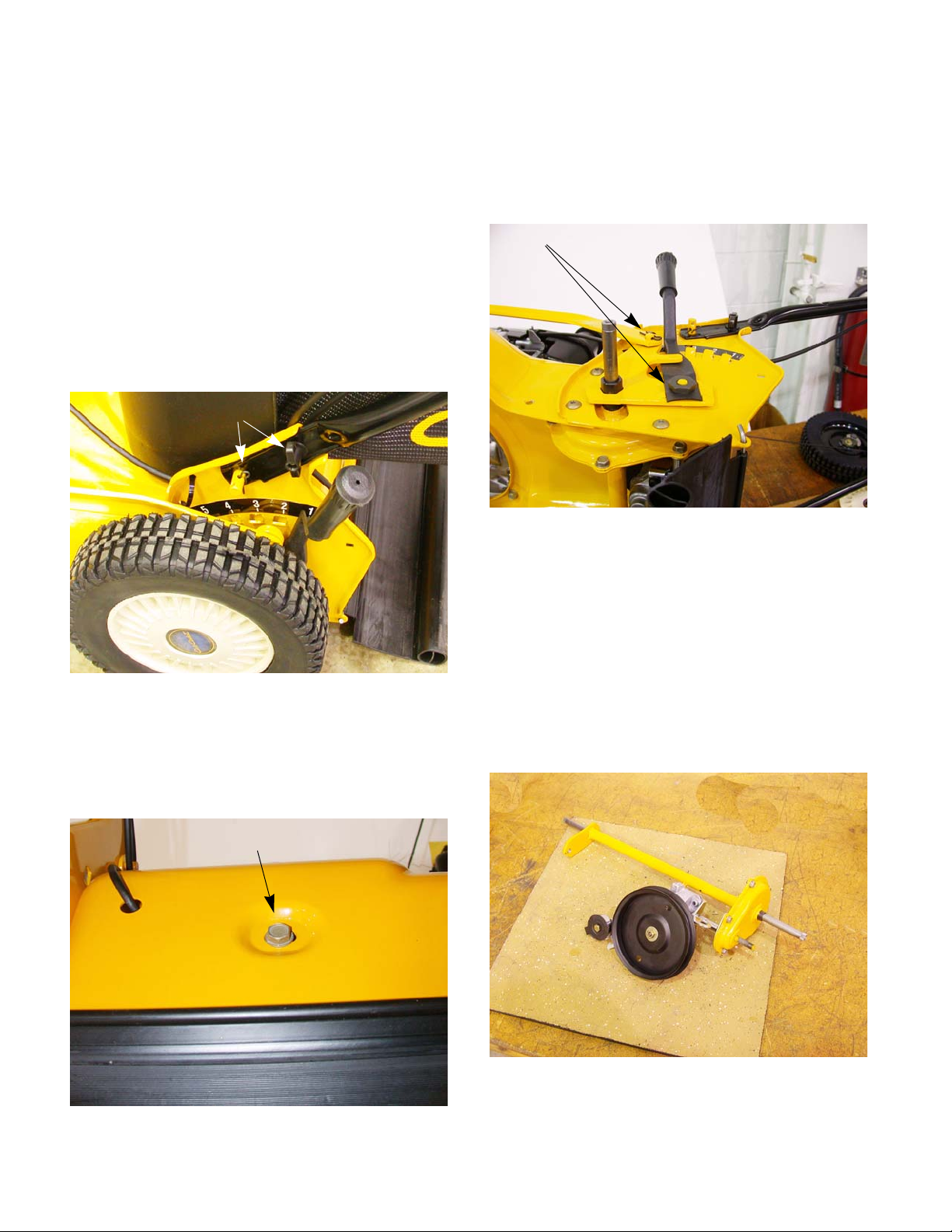
4.7. Remove the nut that holds the height adjuster
handle on using a 7/8” wrench.
4.8. Remove the hairpin clip that holds the height
adjuster linkage to the lever. Disconnect the
height adjuster linkage. See Figure 4.8.
Remove nut and hair pin clip
Figure 4.8
4.9. Remove the four screws holding the handle bar
brackets in place using a T-27 Torx bit.
Figure 4.5
NOTE: When reinstalling the wing nuts, make
sure they are on the out side of the handle bars.
4.6. Remove the bolt that anchors the transmission
to the deck. See Figure 4.6.
Remove this bolt
CAUTION: There is a spring pushing on the axle
housing. Take care to prevent the transmission
and axle housing from flying out.
NOTE: Make a note of which spacer goes
where. They are not interchangeable.
4.10. Place Transmission and chain case on a bench.
See Figure 4.10.
Figure 4.6
Figure 4.10
4
Page 9

Self-Propelled Mower
4.11. Remove the screws holding the chain case
cover on using a 3/8” wrench. See Figure 4.11.
Figure 4.11
4.12. Inspect the plastic bushing in the chain case
cover and the one on the other end of the axle
assembly for wear . Repl ace as needed.
4.13. Wiggle the chain free from the transmission output shaft. See Figure 4.13.
Transmission output shaft
4.16. Reassemble the chain case in reverse order.
4.17. Remove one of the screws hol din g th e he igh t
adjuster spring in place and loosen the other.
See Figure 4.17.
Height adjuster spring screws
Figure 4.17
4.18. Install the transmission and chain case assembly back in the mower with the axle spacers.
NOTE: Be sure to get the height adjuster spring
hooked onto the axle housing. Push against the
spring and hold it in place to install the handlebar
brackets. Removing the screw mentioned in step
4.17 will make it easier to push against the
spring. See Figure 4.18.
Axle assembly
Figure 4.13
4.14. The axle assembly can now be slid out of the
housing.
NOTE: The sprockets on the axle assembly and
the transmission output shaft are welded in
place and can not be removed.
4.15. With a flat head screw driver, pry the backing
plate off of the chain case housing. The transmission is now free to be removed.
NOTE: The transmission is not serviceable. If it
is in need of repair it must be replaced.
Remove screw
Loosen screw
Height adjuster spring
Figure 4.18
4.19. Install the handlebar brackets.
5
Page 10
Self-Propelled Mower
4.20. After the handle bar brackets are in place, use a
piece of starter rope wrapped over the side of
the height adjuster spring bracket that the bolt
was removed from and pull the spring down until
the screw hole lines up. Reinstall the screw.
4.21. Tighten the screw loosened earlie r.
4.22. Finish reassembling the mower in the reverse
order.
4.23. Test run the mower before returning it to service.
5. ENGINE CONTROL CABLE
5.1. Make sure the engine is off.
5.2. Unhook the Z-fitting from the safety bail.
5.3. Squeeze the tabs on cable jacket (on the bail
end of the cable) together using a pair of pliers
or a ford fuel line disconnect tool. Push the cable
through the bracket. See Figure 5.3.
Z-fitting
Squeeze tabs
Figure 5.3
5.4. Use a pair of pliers, or a ford fuel line discon nect
tool, and squeeze the tabs. Push the cable
jacket through the bracket until the inner cable
lines up with the slot on the bracket.
See Figure 5.4.
Squeeze tabs
Slot
Figure 5.4
6
Page 11

Self-Propelled Mower
5.5. Slide the inner cable through the slot.
See Figure 5.5.
Slot
Figure 5.5
5.6. Unhook the Z-fitting from the blade brake and
discard the old cable.
5.7. Install in reverse order.
6. TRACTION CONTROL CABLE
6.1. Disconnect the spark plug wire and ground it to
an engine bolt.
6.2. Take measur es to prevent fuel from leaking from
the gas tank.
6.3. Remove the blade as described in blade
removal section.
6.4. Remove the wheels and shroud as described in
the belt removal section.
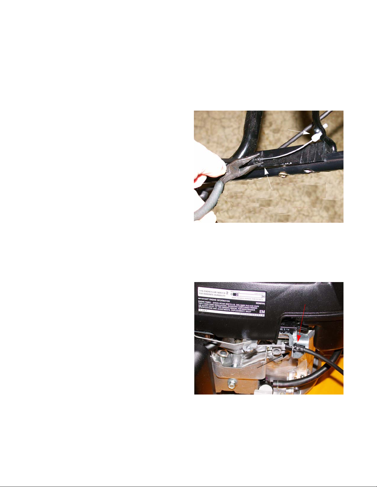
6.5. Unhook the Z-fitting from the Idler bracket.
See Figure 6.5.
Unhook the
Z-fitting
NOTE: The only adjustment on this cable is
moving the Z-fitting from on hole to another on
the safety bail.
5.8. Test run the mower before returning it to service.
Figure 6.5
6.6. Squeeze the tabs together on the cable jacket,
using a pair of pliers or a ford fuel line disconnect tool, and push it through the bracket.
See Figure 6.6.
Squeeze tabs together
Figure 6.6
6.7. slide cable out of the deck.
7
Page 12
Self-Propelled Mower
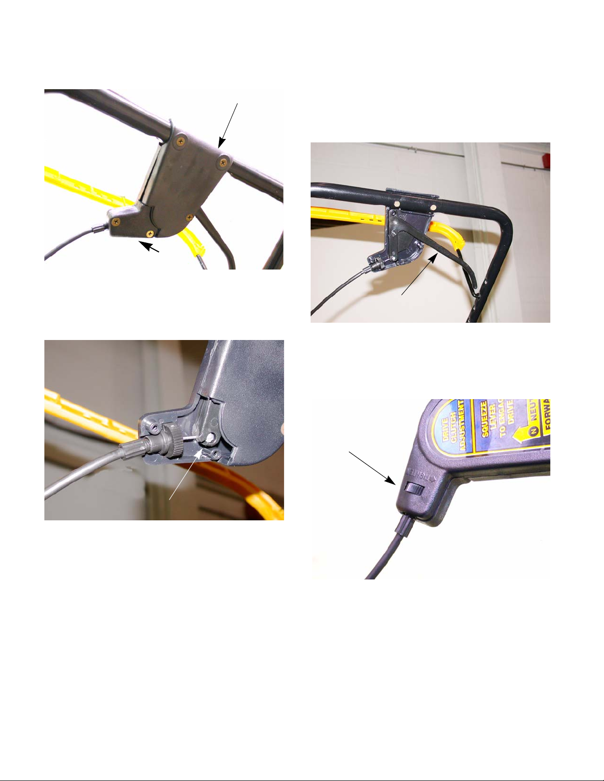
6.8. Remove the mounting cap. See Figure 6.8.
Lower handle cover
Mounting cap
Figure 6.8
6.9. Disconnect the barrel end of the cable by align-
ing the cable with the slot on the control lever
and sliding it out. See Figure 6.9.
Align cable with slot
and slide it out
6.10. Slide cable out of the cable ties on the handle
bar and discard.
NOTE: If the control lever needs repair take the
lower handle cover off and replace the control
lever. See Figure 6.10.
control lever
Figure 6.10
6.11. Reinstall in reverse order.
6.12. To adjust the traction control, turn the thumb
wheel in the control handle. See Figure 6.12.
Slot
Figure 6.9
Thumb wheel
Figure 6.12
6.13. Adjust the cable so that:
• The wheels drive with sufficient force when the
handle is squeezed.
• It takes reasonable effort to squeeze the lever.
• The wheels disengage completely when handle
is released.
8
Page 13

7. FRONT AXLE
7.1. Disconnect and ground the spark plug wire.
7.2. Take measur es to prevent fuel from leaking from
the gas tank.
7.3. Remove the front wheels.
7.4. Remove the hairpin clip that holds the height
adjuster linkage from the left front wheel and disconnect the linkage. See Figure 7.4.
Remove wheel
Remove
hair pin clip
Self-Propelled Mower
Figure 7.4
7.5. Remove the four screws holding the front axle
on. See Figure 7.5.
four screws
Figure 7.5
7.6. Slide the front axle assembly out.
7.7. Reverse the covered process to install the front
axle.
7.8. Run the mower before returning it to service.
9
 Loading...