

Page 1

Professional Shop Manual
CC 500 EL
NOTE: These materials are for use by trained technicians who are experienced in the service and repair of outd oor power
equipment of the kind described in this publication, and are not intended for use by untrained or inexperienced individuals.
These materials are intended to provide supplemental information to assist the trained technician. Untrained or inexperienced individuals should seek the assistance of an experienced and trained professional. Read, understand, and follow all
instructions and use common sense when working on power equipment. This includes the contents of the product’s Operators Manual, supplied with the equipment. No liability can be accepted for any inaccuracies or omission in this publication,
although care has been taken to make it as complete and accura te as possible at the time of publication. However, du e to
the variety of outdoor power equipment and continuing product changes that occur over time, updates will be made to these
instructions from time to time. Therefore, it may be necessary to obtain the latest materials before servicing or repairing a
product. The company reserves the right to make changes at any time to this publication without prior notice and without
incurring an obligation to make such changes to previously published versions. Instructions, photographs and illustrations
used in this publication are for reference use only and may not depict actual model and component parts.
© Copyright 2007 MTD Products Inc. All Rights Reserved
MTD Products Inc. - Product Training and Education Department
FORM NUMBER - 769-03332
6/2007
Page 2

Page 3

Table of Contents
Chapter 1: Introduction..........................................................................................................1
Professional Shop manual intent...........................................................................................1
Assembly .............................................................................................................................1
Understanding model and serial numbers.............................................................................2
Chapter 2: Electrical System .................................................................................................3
Basics of electricity...............................................................................................................3
Electrical circuits...................................................................................................................5
Tools ....................................................................................................................................7
Components and testing techniques......................................................................................8
Chapter 3: Repair Procedures .............................................................................................13
General safety warning........................................................................................................13
Blades .................................................................................................................................13
Switch box assembly...........................................................................................................15
To replace the switch box....................................................................................................16
Motor ................................................................................................................................17
Motor mount .......................................................................................................................18
Rectifier...............................................................................................................................18
i
Page 4

ii
Page 5

CHAPTER 1: INTRODUCTION
INTRODUCTION
Professional Shop Manual Intent
This Manual is intended to provide service dealers with
an introduction to the electrical and mechanical
aspects of the new electric mower.
Disclaimer: This manual was written using a pilot unit.
The information contained in this manual is correct at
the time of writing. Both the product and the information about the product are subject to change without
notice.
This manual covers the newly designed th ird generation of 19” AC powered (corded) electric mowers. The
mower is to be designated 18A-182-xxx and is to be
introduced during the 2007-2008 season.
MTD Products has made two previous generations of
electric mower. The first generation was produced from
1996 to 1998. it was designated 186-407-xxx, 18A407-xxx and 18A-707-xxx. The second generation of
electric mowers were produced from 2001 to 2002. The
second generation of electric mowers shared the same
model numbers with the first generation.
The first generation of electric mowers used a bail
operated switch and the second generation used a
lever operated switch. Very few parts are interchangeable between the first and second generation mowers.
The electrical theory is the same for all three generations of electric mower. However the test procedures
will vary between the different generations. The service
procedures for the first generation of electric mower
can be found in the 1996 Service Update Seminar
Book (form number 770-8877L). The service procedures for the second generation of electric mower can
be found in the 2002 Technical Handbook (form number 770-8877S).
About the text format:
NOTE: is used to point-out information that is
relevant to the procedure, but does not fit as a
step in the procedure.
CAUTION: Indicates a potent ially hazardous situation that, if not avoided, may result in minor or
moderate injury. It may also be used to alert
against unsafe practices.
DANGER: Indicates an imminently hazardous
situation that, if not avoided, will result in death
or serious injury. This signal word is to be lim
ited to the most extreme situations.
WARNING: Indicates a potentially hazardous
situation that, if not avoided, could result in
death of serious injury.
• Bullet points: indicate sub-steps or points.
Disclaimer: This Professional Shop Manual is
intended for use by trained, professional technicians.
• Common sense in operation and safety is
assumed.
• In no event shall MTD or Cub Cadet be liable for
poor text interpretation, or poor execution of the
procedures described in the text.
• If the person using this manual is uncomfortable
with any procedures they encounter, they should
seek the help of a qualified technician or Cub
Cadet Technical Support.
-
1
Page 6

INTRODUCTION
Fasteners:
• Most of the fasteners used on the vehicle are
sized in fractional inches. Some are metric.
For this reason, wrench sizes are frequently
identified in the text, and measurements are
given in U.S. and metric scales.
• If a fastener has a locking feature that has
worn, replace the fastener or apply a small
amount of releasable thread locking compound
such as Loctite® 242 (blue).
• Some fasteners like cotter pins are single-use
items that are not to be reused. Other fasteners
such as lock washers, retaining rings, and internal cotter pins (hairpin clips) may be reused if
they do not show signs of wear or damage. This
manual leaves that decision to the judgement of
the technician.
Assembly:
Torque specifications may b e noted in the part of the
text that covers assembly or they may also be summarized in tables along with special instructions regarding
locking or lubrication. Whichever method is more
appropriate will be used. In many cases, both will be
used so that the manual is handy as a quick-reference
guide as well as a step-by-step procedure guide that
does not require the user to hunt for information.
The level of assembly instructions provided will be
determined by the complexity and of reassembly, and
by the potential for unsafe conditions to arise from mistakes made in assembl y.
Some instructions may refer t o other parts of the manual for subsidiary procedures. This avoids repeating
the same procedure two or three times in the manual.
Understanding model and serial numbers
The model number is 18A-182-710. The break d own of
what the number mean is as follows:
• 18 - - - - - - - - - indicates that this is an electric
mower
• - - A - - - - - - - - indicates the sales level
• - - - - 18 - - - - - indicates the series and trim
• - - - - - - 2 - - - - indicates it is AC powered
• - - - - - - - - 710 indicates that it is Cub Cadet
The serial number is 1J056G10005. The serial number
reads as follows:
1...........................engineering level
..J.........................month of production (J = October)
.....05....................day of the month
.........6..................last digit of the year
...........G................plant it was built in
..............1.............assembly line number
.................0005.....number of unit built
Additional technical and service information may also
be available to our company authorized service center
personnel through our company corporate offices,
regional parts distributors and regional service center
field support personnel. Please contact the de signated
support office in your area or our corporate offices
directly should further service information be needed.
Cub Cadet LLC
P.O. Box 368022
Cleveland, OH 44136
Telephone: (330) 273-8669
www.cubcadet.com
2
Page 7
CHAPTER 2: ELECTRICAL SYSTEM
ELECTRICAL SYSTEM
Basics of electricity
In order to diagnosis any electrical system there are
few things the technician must understand:
• Basic electrical values: voltage, current and
resistance
•Ohm’s law.
• Kirchhoff’s current law.
• Kirchhoff’s voltage law.
• How the system is wired together.
The first electrical value to be discussed is Voltage.
• Voltage is the “pressure” that electricity has. It is
the amount of force pushing electrons through a
circuit.
• This pressure is measured in volts.
• The capital letter “V” is used to represent volts.
The second electrical value is Current:
• Current is the “flow” of electricity. It is the amount
of electrons flowing in circuit.
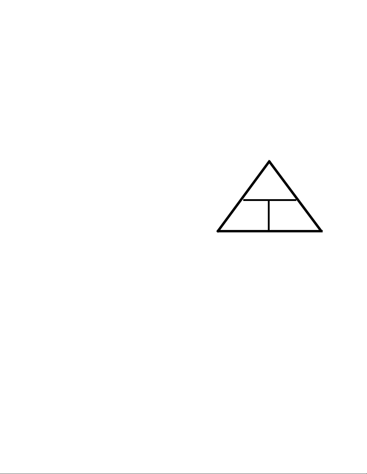
Ohm’s law
Ohm’s law state that voltage is the product of resistance times current. It is written as V=IxR. An example
of how ohm’s law works goes like this: It takes 1 volt to
push 1 amp through a resistance of 1 ohm (1=1x1).
Ohm’s law can be drawn in a triangle. When using the
triangle, cover the value to be found, and the two val
ues left exposed signify how to obtain that value.
See Figure 2.1.
-
V
I
R
• The flow of current is measured in Ampe res or
Amps for short.
• The capital letter “I” is used to represent Amps.
The third and final value is Resistance:
• Resistance is the opposition to current flow. It is
a restriction that slows down the flow of current.
• Resistance is measured in Ohm’s.
• The greek letter omega “Ω” or the capital letter
“R” is used to represent Ohm’s.
Figure 2.1
As an example if the “R” is covered, the “V” is over the
“I” which means V is divided by I. If the “V” is covered,
“I” and “R” is exposed, meaning IxR and so on.
3
Page 8

ELECTRICAL SYSEM
Kirchhoff’s current law
Kirchhoff’s current law deals with nod es. No des a re th e
junction of two or more wires or the junction of a wire to
a component.
Kirchhoff’s current law states that what ever current
goes into a node must come out.
As an example: Three wires are connected with a wire
nut. one wire has 5 amps going into the wire nut. The
sum of the current coming out of the other two wires
must equal 5 amps. That could be 3 amps in one wire
and 2 amps in the other or it could be 2.5 amps in each
wire, but the total must be the same as the current
coming in.
5 Amps
See Figure 2.2.
Node
3 Amps
2 Amps
AC electricity
AC electricity is used to provide electricity to homes
and businesses because it can be easily transmitted
over long distances. Some house hold products can
run on straight AC power while most will convert it to a
usable DC form internally.
AC or alternating current is a current or voltage value
that varies with time and has an average value of zero.
If the current or voltage is observed using an oscillo
scope, the waveform will look like a sine wave. this
means it will be positive for awhile then it will be nega
tive for awhile. The time spent positive will equal the
time spent negative. Since it spends just as much time
positive as negative, the positive values cancel out the
negative values leaving an average value of zero.
Figure 2.3.
AC wave form
1 Cycle
-
-
See
+
Figure 2.2
Kirchhoff’s voltage law
Kirchhoff’s voltage law deals with voltage drops. A voltage drop is the amount of voltage used up or “dropped ”
by a resistance in the circuit. Ohm’s law stated that V =
IxR, every component in a circuit has resistance, even
the wires. T o push current through a resistance, it takes
voltage. Kirchhoff’s voltage law states that the sum of
all the voltage drops equals the source voltage.
An example: a circuit has a battery of 12V, a light bulb
that creates 3 ohms of resistance and there is 4 amps
of current in the circuit. The wires are assumed to have
0 ohms, if the proper size wire is used and there is no
corrosion in the wire, the resistance will be too small to
worry about. The light bulb uses 12 volts (4 amps x 3
ohms = 12 volts). the battery has 12 volts that equals
the 12 volts used by the light bulb.
Figure 2.3
Since AC varies with time, the time or phase angle of
the waveform is needed to compute voltage and cur
rent. This manual will not go into how to do this. AC is
only mentioned here as a reference. This mower is
plugged into AC electricity, but it will change the elec
tricity to a DC waveform to power the motor.
-
-
-
4
Page 9

ELECTRICAL SYSTEM
DC electricity
Most outdoor power products will use DC electricity to
power its electrical systems. The simple way to look at
DC electricity is that current only flows in one direction.
The value of the current or voltage can vary, but as
long as it does not change polarity it is DC electricity.
The wave form of a battery operated DC system is a
straight line.
DC wave form
See Figure 2.4.
Electric circuits
All circuits have some basic rules that must be followed:
1. All circuits must have at least one voltage
source. It is could be a battery, an altenator or
both.
2. All circuits must have a load. To make a circuit
with out a load is the same as shorting out the
power source. A load could be:
•a lamp
•a motor
•a resistor
• a starter
3. All circuits must have a complete path back to
the voltage source. This is also known as having
continuity.
4. Most circuits have additional components like
switches and fuses.
Figure 2.4
The voltage in a DC system does not change polarity
like AC. This mower uses a rectifier to covert AC volt
age into DC voltage. The rectifier operation will be covered in a later section of this chapter.
-
5
Page 10

ELECTRICAL SYSEM
Types of circuits
There are three ways a circuit can be wired. They are:
•Series
• Parallel
• Series/parallel
Series
• Series circuits are wired so that the current has
only one path to follow.
Battery
See Figure 2.5.
Switch
Bulb
Series/parallel
Series/parallel circuits have some sections wired in
series and some in parallel.
Circuit failures
There are three types of failures that can occur in an
electrical circuit:
See Figure 2.7.
Figure 2.7
Figure 2.5
Parallel
Parallel circuits are wired so that current has multiple
paths to follow.
See Figure 2.6.
Figure 2.6
1. Shorts
2. Opens
3. Increased resistance
Shorts
A short is when electricity takes a path that it was not
designed to take bypassing a component in the cir cuit.
An common example of a short is the wire that chafed
through. The bare copper will short the circuit when it
touches a ground source.
Opens
An open is when current can not complete its path back
to the power source.
A common example of this is a blown fuse.
Increased resistance
Increased resistance is as the name implies, an
increase in resistance.
Arguably the most common electrical failure, and the
hardest to find, is when there is a loose connection or
corrosion. It is not an open because there is some cur
rent that can get through, but the increase in resistance
is enough to affect the circuit
-
6
Page 11

Tools
ELECTRICAL SYSTEM
• Digital volt ohm meter
• Wiring or a schematic diagram.
Equipment that may be useful:
• Fused jumper wires.
• Hand tools to gain access to components.
• Flash light.
CAUTION: A test light can not be used on this
mower. The system voltage is 120 volts. It will
destroy the test light and may result in injury to
the technician.
Digital volt ohm meter
Digital volt ohm meters or DVOMs are the most useful
tool to trouble shoot any electrical system. Depending
on the model of DVOM used, DVOMs can measure
Volts, Amps, Ohms and more. DVOMs are a must
when working on circuits with solid state components
(microchips). They have very high impedance, that
means they have very high resistance and pull very lit
tle current from the circuit. Use of analog equipment or
test lights will pull enough current to damage the micro
chips in the circuit. See Figure 2.8.
-
-
NOTE: The only exception to this is when using
an inductive amp clamp.
When measuring resistance, the component must be
isolated from the circuit.
CAUTION: The meter has it’s own power source
to measure resistance. Connecting the meter to
a component that has current going through it
will damage the meter (usually beyond repair).
Inductive amp meter
An inductive amp meter, sometimes referred to as an
“amp clamp” or clamp meter, measures current follow
ing through a wire by the magnetic field create d a ro und
the wire. Clamp meters are very important when deal
ing with currents over 10 amps. A DVOM typically can
not measure current over 10 amps. Clamp meters are
also helpful because they can read current in a circuit
without opening it up to hook the meter into the circuit.
See Figure 2.9.
-
-
Figure 2.8
When measuring volts, always hook the meter in par allel with the circuit. That means do not disconnect the
component where measuring voltage.
When measuring current the meter must be connected
in series with the component to be measured. That
means opening the circuit and having the circuit go
through the meter.
Figure 2.9
Wiring or a schematic diagram
A wiring or a schematic diagram is very important in
troubleshooting a circuit. The d iagram shows how the
circuit was designed and what paths the electricity is
suppose to flow.
Fused jumper wires
Fused jumper wires are handy to he lp find bad groun ds
or to jump across switches for testing purposes.
CAUTION: Only use fused jumper wires. If there
is a short in the circuit, using an unfused jump
could damage components in the circuit further.
7
Page 12

ELECTRICAL SYSEM
Components and testing techniques
In this section, the function and tes t pr oced ure s of indi vidual components will be looked at.
Switches
In order to bench test a switch, the way it operates
must be known. All switches either open a circuit or
close a circuit. The difference between switches is their
resting state and how many circuits they control. When
the switch controls more than one c ircuit, it could have
one side normally open and the other normally closed.
It could also have all sides the same.
Normally closed switches (NC)
A switch that while resting (off) closes (has continuity or
allows current to flow through it) a circuit is called a nor
mally closed switch. when the switch is activated it will
open the circuit.
Normally open switches (NO)
A switch that is open (does not have continuity) when
in a resting state is called a normally open switch.
When activated the switch will close the circuit. The
tabs for a normally open switch generally are
unmarked.
The switch used in this mower is known as a double
pole double throw switch. Double pole basically means
that it has two separate switches inside one housing
that act as one. Double throw means that each switch
has a normally open contact and a normally closed
contact.
See Figure 2.10.
-
Testing a switch
When testing a double pole double throw switch, treat it
as two switches. Test one side of the switch in the open
and closed state then do the same on the othe r side. To
test a switch:
NOTE: There is usually a schematic drawing on
the side of the switch that will show which tabs
are in what circuit.
1. Uplug the power cord.
2. Remove and open the switch box assembly by
following the steps described in chapter 3 Repair
Procedures.
3. Remove the switch from the circuit.
4. Set the DVOM to the ohms scale (
5. With the switch in the off position touch one
probe to the one of common tabs and the other
probe to the NC tab for that circuit.
NOTE: The DVOM should read zero resistance.
6. Move the probe from the NC tab to the NO tab.
NOTE: The meter should show an open circuit.
7. With the probes still attached, turn the switch on.
The readings should reverse, NO should have
zero resistance and a NC switch should indicate
an open circuit.
8. Repeat for all the circuits in the switch
9. If the switch fails in any of the tests, replace the
switch.
See Figure 2.10.
Ω).
DPDT switch
Schematic drawing
Figure 2.10
NOTE: The part number for just the switch is
725-04435.
10. Install the switch box assembly by following the
above steps in reverse order.
11. Test run the mower before returning to service.
8
Page 13

ELECTRICAL SYSTEM
Circuit breakers
Circuit breakers are safety devices that open a circuit
when the current flow reaches a certain level. This
helps to prevent components from being damaged by
the high current flow.
A circuit breaker is basically a switch. When current
flows through a circuit, it creates heat. The higher the
current flow, the more heat that is created. As current
flows through a circuit breaker the contacts heat up. If
the current heats the contacts enough, they will release
the piece used to jump across the contacts. That will
open the circuit and prevent current fl ow.
Some circuit breakers are self resetting, meaning that
as they cool down, the circuit is closed. The circuit
breaker on this mower has a manual reset function.
That means that a button has to be pushed in to
restore the connection between the contacts. The cir
cuit breaker may have to cool down for a few minutes
before the breaker can be reset.
See Figure 2.11.
-
To test a circuit breaker
1. Let the circuit breaker cool down for at least five
minutes and reset the breaker.
NOTE: If the circuit breaker will not reset, unplug
the wires from the breaker and let it cool down
for five minutes. If it still will not reset, the
breaker is bad and must be replaced.
2. If not already done, remove the circuit breaker
from the circuit by unplugging the two wires.
NOTE: See chapter 3 Repair Procedures for the
steps to open the switch box assembly.
3. Check for continuity between the two tangs. See
Figure 2.12.
NOTE: If there is no continuity between the two
tangs, the breaker is bad and must be replaced.
Reset button
Figure 2.11
Figure 2.12
NOTE: The part number for just the circuit
breaker is 925-1712.
9
Page 14

ELECTRICAL SYSEM
Diodes
A diode acts like a one way valve. They allow current to
flow in only one direction. There will be a band on one
end of the diode. This indicates the negative side of the
diode. Most DVOMs have the ability to test a diode.
See Figure 2.13.
Silver band
(-)
electrons flow from the negative to the positive.
Figure 2.13
(+)
3. Attach the negative lead of the DVOM to the side
of the diode with a band on it.
4. Place the positive lead on the other side of the
diode.
5. There should be continuity. See Figure 2.15.
Continuity
Silver band
(-)
Figure 2.15
(+)
Testing a diode
1. Isolate the diode in the circuit.
2. Set the DVOM to the diode scale.
See Figure 2.14.
Diode scale
Figure 2.14
6. Switch the leads.
7. The meter should indicate no continuity.
See Figure 2.16.
No continuity
Silver band
(-)
Figure 2.16
8. If the results do not match the above, replace the
diode.
(+)
10
Page 15

ELECTRICAL SYSTEM
Cord l
Rectifier
The rectifier is a device that will take AC voltage and
change it in to DC voltage. Rectifiers are made up of
diodes. A half wave rectifier can be something as sim
ple as a diode placed in the circuit to block the negative
half for the AC wave form.
Negative deflections blocked
See Figure 2.17.
Figure 2.17
Because the rectifier is just reversing the negative side
of the AC wave form, it does not have a smooth output
wave form.
-
Negative deflections have been reversed
See Figure 2.19.
NOTE: For a motor, that is fine. If using electronic devices, the wave form would need to be
smoothed out.
Figure 2.19
This mower uses a full bridge rectifier. That is just four
diodes wired in such a way as to take the negative side
of the AC wave form and make it positive.
2.18.
AC
power
Figure 2.18
See Figure
Rectifier
Testing the rectifier
The rectifier can only be tested while power is supplied
to it.
CAUTION: Use extreme caution while working
with electricity. Touching the circuit while it is
energized is a shock hazard.
To test the rectifier:
1. Remove the motor cover following the steps
described in chapter 3 Repair Procedures.
2. Plug the mower in using an appropriate size
extension cord.
CAUTION: Use of the wrong sized extension
cord can result in damage to the motor or a ther
mal failure of the cord.
-
ength
in feet
25 50 100 150
Wire gauge
size
16 16 14 12
11
Page 16

ELECTRICAL SYSEM
3. Connect a DVOM, set to read AC voltage, to the
AC input (the black and white wires from the harness) to the rectifier. See Figure 2.20.
AC input
AC input
Figure 2.20
4. Turn the mower on. Read the voltage on the
DVOM.
NOTE: The meter should read between 110 125 volts.
Motor
An electric motor is a device that converts electrical
energy into mechanical force. The motor used on this
mower is not serviceable. The motor is diagnosed by a
process of elimination.
Test the circuit breaker first. then test the switch and
the rectifier. If they are working properly but the motor
is not, replace the motor.
Returning to service
After diagnosing and repairing any fault in an electrical
circuit and any other repairs needed, the following
steps should be taken:
1. Test run the machine to verify that the condition
has been repaired.
2. Cycle the circuit at least ten times.
3. Allow the machine to cool down for a couple of
hours.
4. Re-test the machine to verify the co ndition does
not re-appear.
5. If the condition does not re-appear, return the
machine back to service.
5. Turn off the mower.
6. Connect the DVOM, set to read DC voltage, to
the DC outputs (the wires going to the motor).
7. Turn the mower on. Read the voltage on the
DVOM.
NOTE: It is normal for the DC voltage to be a little higher than the AC voltage, but it should be
close to the AC voltage.
12
Page 17

CHAPTER 3: REPAIR PROCEDURES
REPAIR PROCEDURES
General safety warning
Whenever working on an electric lawn mower, unplug
the power cord. Only plug the power cord in if electricity
is needed to preform a test.
WARNING: Use caution while working around
this lawn mower. A lawn mower that is plugged
in creates an electrocution hazard or may start
unexpectedly.
Blades
The condition of the blades will greatly effect the quality
of the cut.
The blades should be sharpened and balanced after
every hour of cutting, depending on local conditions. A
dull blade tears the grass instead of cutting it. Torn
grass blades leaves a rough look and makes the grass
vulnerable to diseases.
Blades need to be examined for damage before sharpening. Blades must be balanced after sharpening to
reduce the vibrations felt from the deck.
Bent blades are a sign of a blade impact. When a bent
blade is found, the blades must be replaced and the
motor inspected for a bent shaft and cracked motor
mount.
To replace the blade:
WARNING: When removing the cutting blade for
sharpening or replacement, protect your hands
with a pair of heavy gloves or use a heavy rag to
hold the blade. Be certain to disconnect the
power supply.
1. Disconnect the power supply to the mower. Turn
the mower on its side.
2. Block the blade to prevent it from turning when
the bolt is removed. See Figure 3.1.
NOTE: The blade can be blocked using a piece
of wood between the blade and the mower deck
or use of a commercially available blade locking
device.
Blade holder
The cutting deck on this mower is mounted with a slight
rake, meaning that the front of the deck is a 1/4” - 3/8”
lower than the rear of the deck. T his is very important
to get the proper air flow in the deck so that the blades
can make the grass blades stand up to get cut.
The air flow in the cutting deck is generated by the
spinning blades. If the blades are mounted upside
down, the air flow will be reversed pushing the grass
down instead of standing up.
NOTE: Blades that are mounted upside down,
increase the risk of blade damage from struck
objects.
NOTE: The blade also act s as the cooling fan for
the motor. The motor will over heat if the blade is
mounted upside.
Figure 3.1
NOTE: The blade locking tool pictured above is
available through MTD parts. The part number is
BB-100.
13
Page 18

REPAIR PROCEDURES
3. Loosen and remove the blade bolt, locking plate,
and blade using a 24 mm wrench. See Figure
3.2.
24 mm wrench
Figure 3.2
NOTE: Make certain to replace the parts in the
exact order in which they were removed. When
installing the cutting blade, be sure it is installed
with the curved ends pointing towards the
mower deck and not towards the ground. See
Figure 3.3.
4. The blade can be sharpened with a file or on a
grinding wheel.
NOTE: To properly sharpen the cutting blades,
remove equal amounts of metal from both ends
of the blades along the cutting edges, pa rallel to
the trailing edge, at a 25° to 30° angle.
WARNING: An unbalanced blade will cause
excessive vibration when rotating at high
speeds. It may cause damage to mower and
could break causing personal injury.
5. Place the cutting blade, locking plate, and blade
bolt on the motor shaft.
Figure 3.3
6. Tighten the blade bolt to a torque of 170-220 inlbs (19 - 25Nm).
WARNING: The blade hardware is not only used
to attach the blade assembly, but is also an insu
lated safety device and should never be altered
in any way. If replacement is necessary, use
original equipment parts.
7. Test run the mower before returning to service.
-
14
Page 19

REPAIR PROCEDURES
Switch box assembly
The switch box assembly is located on the upper handle bar. The switch and circuit breaker are housed
inside of it. To service the switch box assembly:
NOTE: Opening the switch box assembly will
void the warranty on this mower. For warranty
repairs, replace the switch box and harness as a
whole assembly.
1. Unplug the power cord.
2. Slide the safety bail out of the switch box assembly.
3. Remove the two mounting screws usin g a T- 27
Torx driver. See Figure 3.4.
Mounting screws
5. Peel back the label on the side of the switch box
assembly to expose the seam. See Figure 3.6.
Seam
Figure 3.6
6. Remove the three screws holding the housing
together using a #2 phillips screwdriver. See Figure 3.7.
Figure 3.4
4. Unhook the harness from the clips on the handle
bar. See Figure 3.5.
Clips
Remove screws
Figure 3.7
7. The switch box is now serviceable.
NOTE: The test procedures for the components
of the switch box are in chapter 2 Electrical system.
8. Install the switch box by following the above
steps in reverse order.
9. Test run the mower before returning it to service.
Figure 3.5
15
Page 20

REPAIR PROCEDURES
To replace the switch box:
1. Unplug the power cord.
2. Slide the safety bail out of the switch box assembly.
3. Remove the motor cover by follo wing the steps
describe in the motor section of this chapter.
4. Unplug the wires from the rectifier. See Figure
3.7.
NOTE: Mark the wires or make a drawing to
ensure the wires are hooked up properly when
the switch box is installed.
6. Remove the two mounting screws using a T-27
Torx driver. See Figure 3.9.
Mounting screws
Figure 3.9
7. Unhook the harness from the clips on the handle
bar.
8. Install the switch box assembly by following the
above steps in reverse order.
Rectifier
Figure 3.7
5. Unhook the wiring harness from the motor
mount. See Figure 3.8.
Unhook harness
9. Test run the mower before returning to service.
Figure 3.8
16
Page 21

REPAIR PROCEDURES
Motor
The motor on this mower is a DC permanent magnet
motor. It is not serviceable. The test procedures for this
motor are covered in chapter 2 Electrical system.
To replace the motor:
1. Unplug the power cord.
2. Remove the blade by following the steps
described in the blade section of this chapter.
3. Remove the fan and blade hub from the motor
shaft. See Figure 3.10.
Blade hub
4b. Press in the tab while lifting on the cover.
4c. Repeat steps 4a and 4b on the other slots.
5. Unplug the wires from the rectifier. See Figure
3.12.
NOTE: Mark the wires or make a drawing to
ensure the wires are hooked up properly when
the motor is installed.
Rectifier
4. Remove the motor cover by:
4a. Place a flat head screwdriver into one of the
four slots in the cover. See Figure 3.11.
Push in tab
with a flat head screwdriver
Figure 3.12
6. Remove the four mounting screws. See Figure
3.13.
NOTE: Use care to catch the motor while remov-
ing the mounting screws.
Mounting screws
Figure 3.13
Figure 3.11
7. Install the motor by following the above steps in
reverse order.
8. Test run the mower before returning it to service.
17
Page 22

REPAIR PROCEDURES
Motor mount
To replace the motor mount:
1. Unplug the power cord.
2. Remove the motor by following the steps
described in the previous section of this manual.
3. Remove the three mounting scre ws using T-40
torx driver. See Figure 3.14.
Mounting screws
Rectifier
To replace the rectifier :
1. Unplug the power cord.
2. Remove the motor cover by following the steps
described in the motor cover section of this
chapter.
3. Unplug wires from the rectifier.
NOTE: Tag the wires so that they go back on the
proper tabs. Failure to do so will prevent the
mower from working and may cause damage to
the rectifier.
4. Remove the screw in the center of the rectifier
using a phillips screw driver. See Figure 3.15.
AC DC +
Black
wire from
harness
Red wires
Figure 3.14
4. Remove the motor mount from the deck of the
mower.
5. Install the motor mount by following the above
steps in reverse order.
NOTE: tighten the motor mount scre ws to a
torque of 170-200 in-lbs (19 - 22.5 Nm).
6. Test run the mowe r be fore ret ur nin g to serv ice .
DCBlack wire from
motor
Green
wire
5. Clean any heat sink grease from the rectifier
bracket.
6. Apply new heat sink grease to the back of the
new rectifier.
NOTE: Heat sink grease can be purchased at
any electronic parts store.
CAUTION: Never use bearing grease or silicone
as a substitute. Heat sink grease is design to pull
the heat away from the rectifier, regular grease
and silicone will trap the heat in the rectifier
causing it to fail.
7. Install the rectifier by following steps 1 - 4 in
reverse order.
Remove screw
Figure 3.15
AC
White
wire
8. Test run the mower before returning to service.
18
 Loading...