

Page 1
Professional Shop Manual
32 cc Back Pack Blower
NOTE: These materials are for use by trained technicians who are experienced in the service and repair of outdoor power
equipment of the kind described in this publication, and are not intended for use by untrained or inexperienced individuals.
These materials are intended to provid e su pp lem ental information to assist the trained technician. Untrained or inexperienced individuals should seek the assistance of an experienced and tr ained professional. Read, understand, a nd follow all
instructions and use common sense when working on power equipment. This includes the contents of the product’s Operators Manual, supplied with the equipment. No liability can be accepted for any inaccuracies or omission in this publication,
although care has been taken to make it as complete a nd accura te as possib le at the time of publica tion. However, due to
the variety of outdoor power equipment and continuing product changes that occur over time, updates will be made to these
instructions from time to time. Therefore, it may be necessary to obtain the latest materials before servicing or repairing a
product. The company reserves the right to make changes at any time to this publication without prior notice and without
incurring an obligation to make such changes to previously published versions. Instructions, photographs and illustrations
used in this publication are for reference use only and may not depict actual model and component parts.
© Copyright 2007 MTD Products Inc. All Rights Reserved
MTD Products Inc - Product Training and Education Department
FORM NUMBER - 769-03584
10/2007
Page 2

Page 3

Table of Contents
Chapter 1: Introduction......................................................................................................... 1
Introduction .........................................................................................................................1
Fasteners .............................................................................................................................1
Assembly ............................................................................................................................1
Model and serial numbers................................................................................................... 2
Chapter 2: Maintenance......................................................................................................... 3
Maintenance ........................................................................................................................3
Spark plugs ......................................................................................................................... 3
Air filter .............................................................................................................................. 5
Spark arrestor...................................................................................................................... 6
Fuel filter .............................................................................................................................6
Valve lash ...........................................................................................................................7
Starter.................................................................................................................................. 8
Chapter 3: Trouble shooting ..................................................................................................9
Initial Trouble Shooting...................................................................................................... 9
To check the fuel in the carburetor: ....................................................................................9
Compression testing.......................................................................................................... 11
Chapter 4: Ignition ................................................................................................................14
Troubleshooting the Ignition System ................................................................................14
The ignition system consists of......................................................................................... 14
Module ..............................................................................................................................16
Flywheel ............................................................................................................................17
Chapter 5: Fuel system and carburetor ..............................................................................19
Troubleshooting the Fuel System ..................................................................................... 19
Repairing the fuel system .................................................................................................20
Fuel lines ...........................................................................................................................21
Troubleshooting/Repairing the Carburetor .......................................................................21
Disassembly of the carburetor .......................................................................................... 22
Chapter 6: Blower housing .................................................................................................. 25
Back pack frame ...............................................................................................................25
Blower housing and impeller ............................................................................................26
Page 4
CHAPTER 1: INTRODUCTION
INTRODUCTION
Introduction
The 32cc backpack blower is a full crank, 4-cycle
blower. It was introduced in the 2008 season under a
variety of brand names. This blower has 32cc’s of displacement and produces a maximum of 475 cfm at 150
mph.
Figure 1.1
Disclaimer: This Professional Shop Manual is
intended for use by trained, professional technicians.
• Common sense in operation and safety is
assumed.
• In no event shall MTD be liable for poor text
interpretation, or poor execution of the procedures described in the text.
• If the person using this manual is uncomfortable
with any procedures they encounter, they should
seek the help of a qualified technician.
Fasteners
• Most of the fasteners used on the blower are
sized in fractional inches. Some are metric.
For this reason, wrench sizes are frequently
identified in the text, and measurements are
given in U.S. and metric scales.
• If a fastener has a locking feature that has
worn, replace the fastener or apply a small
amount of releasable thread locking compound
such as Loctite® 242 (blue).
• Some fasteners like cotter pins are single-use
items that are not to be reused. Other fasteners
such as lock washers, retaining rings, and internal cotter pins (hairpin clips) may be reused if
the do not show signs of wear or damage. This
manual leaves that decision to the judgement of
the technician.
Assembly
Torque specifications may be noted in the part of the
text that covers assembly, they may also be summarized in tables along with special instructions regarding
locking or lubrication.
Whichever method is more appropriate will be used. In
many cases, both will be used so that the manual is
handy as a quick-reference guide as well as a step-bystep procedure guide that does not require the user to
hunt for information.
The level of assembly instructions provided will be
determined by the complexity of reassembly, and by
the potential for unsafe conditions to arise from mistakes made in assembly.
Some instructions may refer to other parts of the manual for subsidiary procedures. This avoids repeating
the same procedure two or three times in the manual.
1
Page 5

INTRODUCTION
Model and serial numbers
The model (item) and serial number for this blower are
on a little white sticker with bar code. These are the
numbers needed when ordering parts. This sticker can
be found at the bottom of the starter housing by.
See Figure 1.2.
Model number
Sticker
Fuel tank
Figure 1.2
The model (item) number and serial number are
printed with a small type face, above the bar code.
See Figure 1.3.
Serial number
NOTE: Engine disassembly and reassembly is
not covered in this manual because it is not economical to rebuild the engine.
Model (item) number
Figure 1.3
2
Page 6
CHAPTER 2: MAINTENANCE
Maintenance
MAINTENANCE
The specifics in this manual are aimed at the 32cc back
pack blower, however the contents can be used for
most outdoor power equipment.
As the saying goes “an ounce of prevention is worth a
pound of cure” the same can be said about preventive
maintenance on outdoor power equipment. By changing the spark plug, air filter, and oil in annual intervals
many failures can be avoided. Sometimes just clearing
off yard debris that was collected while in use can
make the difference between a properly r unning piece
of equipment or a failure.
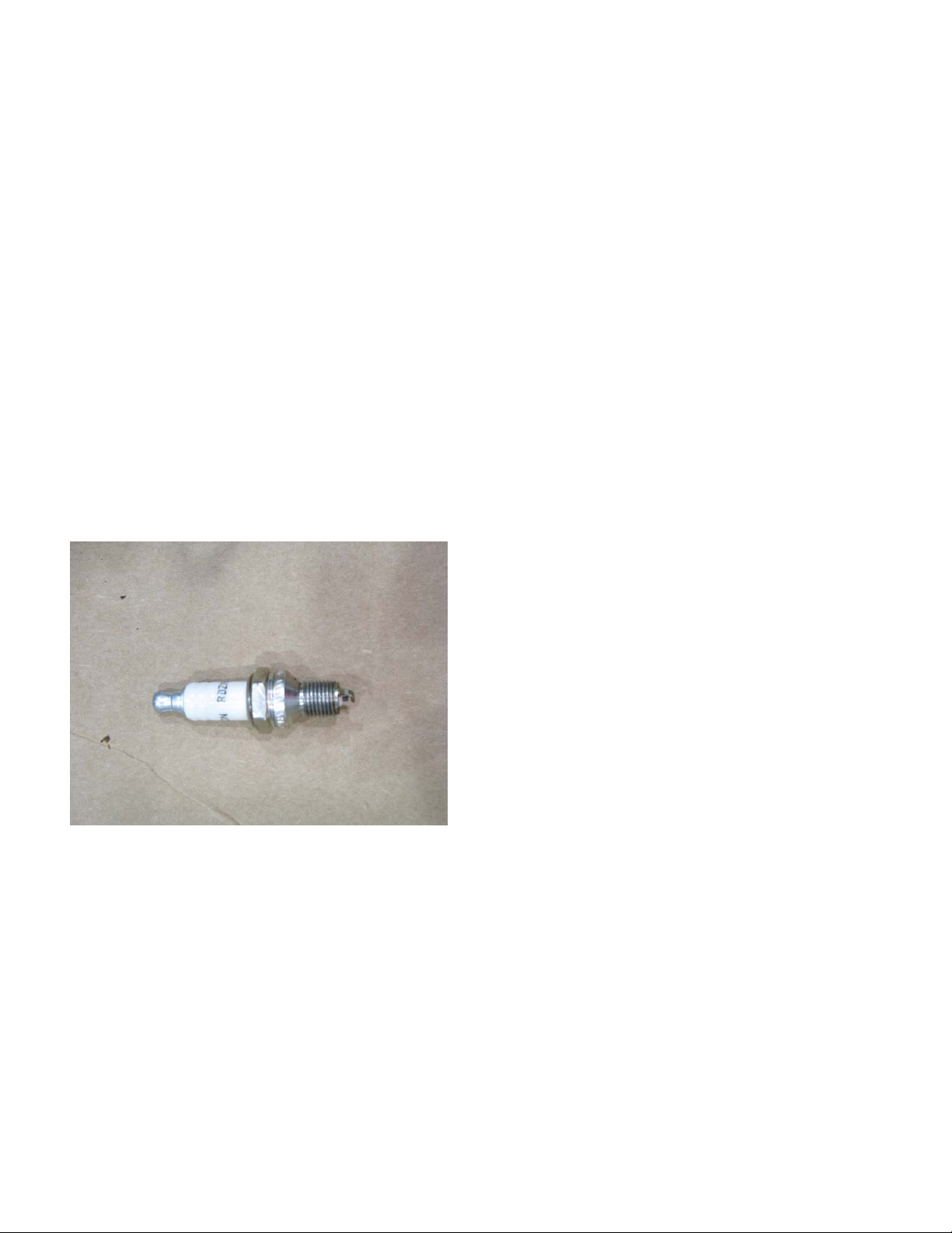
Spark plugs
1. The spark plug used in the 32cc back pack
blower is a Champion RDZ19H gapped to .025”
(.6 mm). See Figure 2.1.
2. Wear rate will vary somewhat with severity of
use. If the edges of the center electrode are
rounded-off, or any other apparent wear / damage occurs, replace the spark plug before operating failure (no start) occurs.
3. Cleaning the spark plug:
NOTE: It is not recommended to clean spark
plugs. Use of a wire brush may leave metal
deposits on the insulator that causes the spark
plug to short out and fail to spark. Use of abrasive blast for cleaning may cause damage to
ceramic insulator or leave blast media in the
recesses of the spark plug. When the media
comes loose during engine operation, severe
and non-warrantable engine dama ge may result.
4. Inspection of the spark plug can provide indications of the operating condition of the engine.
• Light tan colored deposits on insulator and electrodes is normal.
• Dry, black deposits on the insulator and electrodes indicate an over-rich fuel / air mixture (too
much fuel or not enough air)
Figure 2.1
• Wet, black deposits on the insulator and electrodes indicate the presence of oil in the combustion chamber.
• Heat damaged (melted electrodes / cracked
insulator / metal transfer deposits) may indicate
detonation.
• A spark plug that is wet with fuel indicates that
fuel is present in the combustion chamber, but it
is not being ignited.
3
Page 7
Maintenance
Spark plug removal
1. Remove the engine cover by:
1a. Remove the screws that hold the cover in
place.
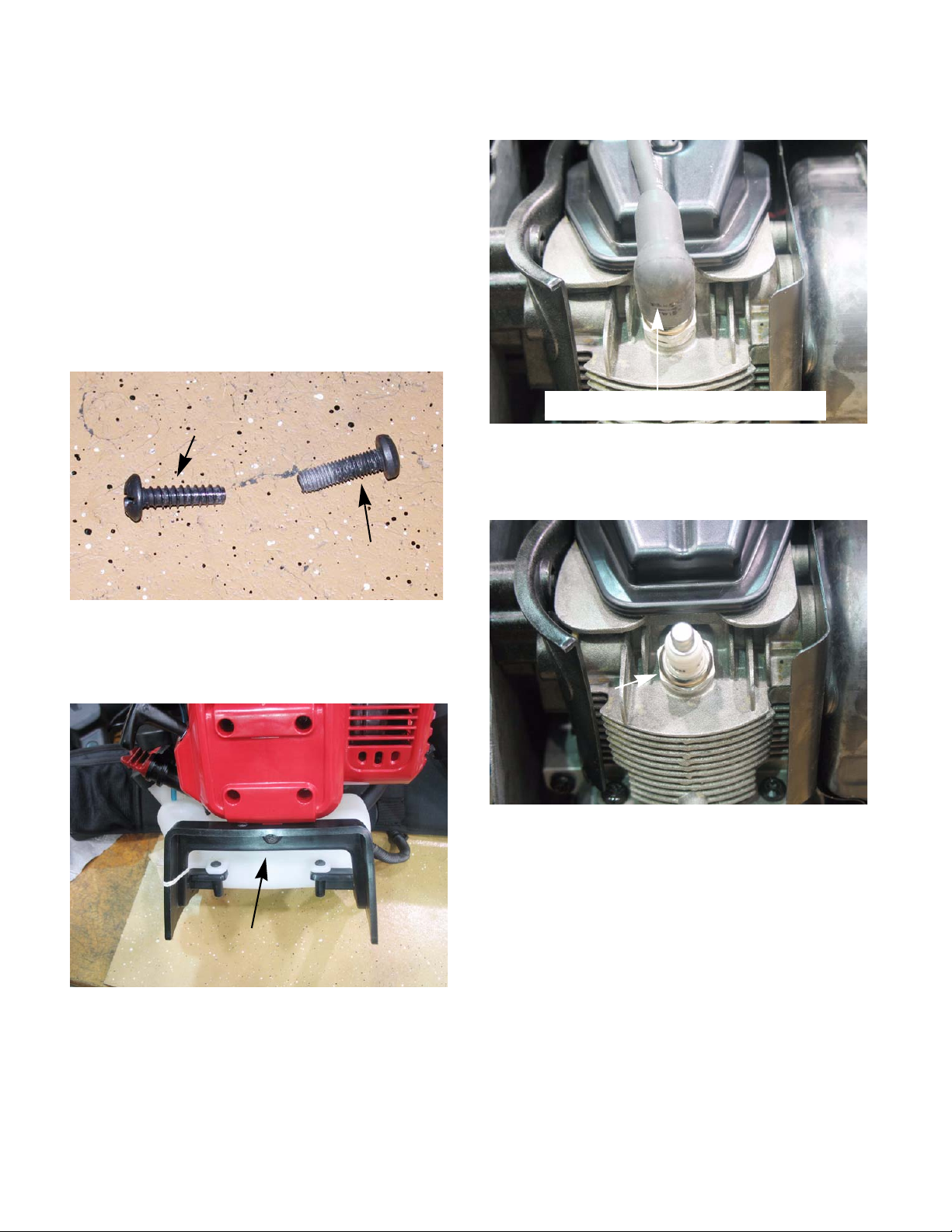
NOTE: There are eight screws for the engine
cover, four that go into the engine block casting
and three that go into the blower housing and
one into the fuel tank bracket. Make sure you put
the machine threaded screws into the casting
and the plastic threaded screws into the blower
housing and fuel tank bracket. See Figure 2.2.
Plastic threaded
screw
Machine threaded
screw
2. Disconnect the spark plug wire. See Figure 2.4.
Disconnect the spark plug wire
Figure 2.4
3. Remove the spark plug using a 5/8” spark plug
socket. See Figure 2.5.
Figure 2.2
1b. Lift the cover up and away, sliding it out from
in between the engine block and the fuel
tank bracket. See Figure 2.3.
Slide cover out from in between
the engine and the fuel tank bracket
Figure 2.3
Remove using
a 5/8” spark plug
socket
Figure 2.5
4. Gap a new plug at .025” (.6 mm).
5. Install the spark plug and tighten to a torque of
120 in. lbs.(12 -15 Nm).
6. Follow steps 1 and 2 in reverse order.
7. Test run the blower in a safe area before returning to service.
4
Page 8
Maintenance
Air filter
A dirty air filter can reduce engine power, increase fuel
consumption and make starting more difficult.
The air filter should be cleaned every 10 hours of use.
8. To clean/replace the air filter:
8a. Press down the on tab of the air filter cover
and swing the cover up. See Figure 2.6.
Press tab
Figure 2.6
8b. Remove the foam air filter. See Figure 2.7.
Foam air filter
Figure 2.7
8c. Wash the air filter with warm soapy water.
Let the filter air dry. DO NOT wring the fil-
ter out. Wringing the filter can tear it.
Squeeze the filter , b ut do not twist it. Put a
1/4 teaspoon (1.25cc) of oil to the filter
and squeeze it through out the filter..
IMPORTANT: Always replace a damaged filter.
8d. Swing the cover back in place. make sure
the tab snaps into place.
5
Page 9
Maintenance
Spark arrestor
The spark arrestor should be checked and/or cleaned
every 10 hours of use.
NOTE: The spark arrestor also serves to keep
blockages out of the exhaust system. Typical
blockages include insect nests built during the
dormant season.
To check/clean the spark arrestor:
1. Remove the engine cover as describe in the
spark plug section of this chapter.
2. Remove the two screws holding the spark arrestor cover in place. See Figure 2.8.
Muffler bolt
Spark arrester
Fuel filter
A dirty fuel filter can result in a lean run condition. The
fuel filter should be replaced every 10 hours of use.
NOTE: The weighted fuel filter (clunk) keeps the
filter submerged in the fuel at any angle of operation. Running the blower without the filter may
allow air to be entrapped in the fuel line creating
a lean run condition at higher RPMs. This will
cause a catastrophic failure of the engine.
To clean/replace the fuel filter:
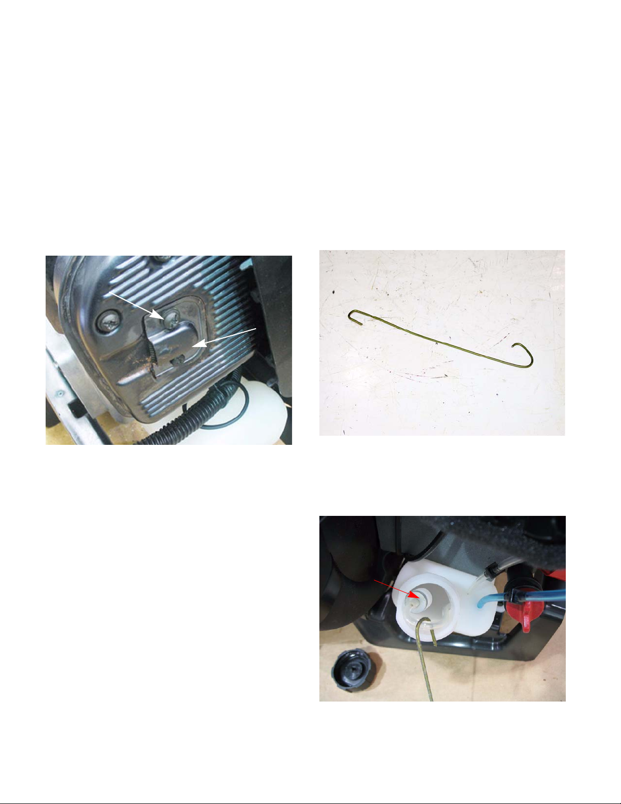
1. To service the fuel filter take a piece of wire and
bend a hook on one end of it. See Figure 2.9.
Figure 2.8
NOTE: The top screw is a muffler bolt and uses
a T-25 to rx driver to remove it. The botto m screw
uses a T-20 torx driver.
3. The screen can now be inspected. If it is blocked
with carbon, it may be:
• Replaced with a new spark arrester screen.
• Cleaned by mechanical means
• Solvent cleaned
• Burned clean using a butane or propane torch.
NOTE: This is an air cooled engine. In order to
work properly there must be good air flow over
the fins of the engine. It is recommend to clean
the cylinder fins of any debris while the engine
cover is removed.
4. Reassemble the blower following the steps just
described in reverse order.
Figure 2.9
2. Remove the gas cap.
3. Stick the hook end of the wire into the fuel tank
and fish out the fuel filter. See Figure 2.10.
Fuel filter
Figure 2.10
6
Page 10

Maintenance
4. Carefully remove the fuel line from the barb on
the fuel filter. Clean or discard the old fuel filter.
See Figure 2.11.
barb
Figure 2.11
5. Inspect the fuel lines. Replace if they are
cracked.
6. Install a new filter by following the steps just covered in reverse order.
Valve lash
To adjust the valves:
1. Remove the engine cover and spark plug by following the steps described in the sp ark plug section of this chapter.
2. Remove the valve cover using a T-25 driver. See
Figure 2.12.
Valve cover
Figure 2.12
7. Test run blower before returning to service.
3. Rotate the crank shaft to bring the piston to top
dead center of the compression stroke (valves
closed).
NOTE: Use a probe in the spark plug hole to
track the piston position.
NOTE: The valve clearance for this engine is
.003”-.006”(.08-.15 mm) for both valve s.
7
Page 11

Maintenance
4. Check the valve lash by placin g a feeler gauge
between the rocker arm and the valv e stem. To
adjust the valve loosen or tighten the fulcrum nut
with a 8mm wrench until there is a slight dr ag on
the feeler gauge when you pull it out.
See Figure 2.13.
Fulcrum nut
Rocker
Feeler gauge
Figure 2.13
5. Inspect the gasket that the valve cover sits on for
damage. If it is damaged or compressed replace
it.
Starter
The starter and engine cover are one piece on this
blower. The procedure for removing it are covered in
the spark plug section of this manual.
The rewind spring underneath the starter pulley is
extremely difficult to work with. Because of this, it is not
economical nor is it recommended to try and service
this starter.
6. Reassemble the blower by following steps 1 and
2 in reverse order.
7. Test run the blower in a safe area before returning to service.
8
Page 12

CHAPTER 3: TROUBLE SHOOTING
Trouble shooting
Initial Trouble Shooting
The first step in diagnosing an engine problem is to
perform the periodic maintenance. A majority of the
poor run or no start conditions will be solved just by
doing the required maintenance. After the periodic
maintenance is done:
1. Drain and inspect the fuel from the fuel tank:
• Look for water.
• Look for dirt.
• Look for discoloration.
• Sniff carefully to see if it smells like varnish.
• Save a sample to show to customer.
To check the fuel in the carburetor:
1a. Get a plain piece of paper.
1b. Divide it into four sections and label them:
• Plain gas
• Two cycle mix
NOTE: Even for a 4-cycle engine, check for oil in
the fuel to see if the customer put motor oil in the
fuel tank.
1c. Get a sample of fuel from the carburetor and
pour it on the section of the paper labeled
sample from carburetor. See Figure 3.1.
Figure 3.1
1d. Place a sample of two cycle mix where it
says two cycle mix, straight gas with
straight gas and straight oil with straight
oil. See Figure 3.2.
• Gas from carburetor
• Straight oil
Figure 3.2
9
Page 13

Trouble shooting
1e. Match the sample from the carburetor to the
other three samples. This will show if the
proper mix is being used or not.
See Figure 3.3.
Figure 3.3
1f. Before returning to service, put fresh fuel/oil
mix in the fuel tank.
2. Inspect the spark plug:
• What does the spark plug look like?
• A wet fowled plug indicates the engine is ru nning
rich
• A light colored coating on the plug would mean
the engine is running lean.
3. Inspect the air filter:
• What does the air filter look like? Dirt-blocked, oil
soaked, missing, wrong filter?
• Look for signs of dirt ingestion.
• A dirty air filter would restrict air flow.
• A missing air filter means that the engine has
ingested dirt that could damage the piston and
cylinder.
Most gasoline engine diagnosis involves isolating pr oblems in the four critical factors an engine needs to run
properly:
Ignition
der, occurring at the right time.
Compression
vert combustion into kinetic motion. It also needs sufficient sealing to generate the vacuum needed to draw
in and atomize the next intake charge.
Fuel
in sufficient quantity, atomized (tiny droplets) and in
correct fuel mix/air proportions.
Flow
of air is constricted on the inlet or exhaust side it will
cause the engine to run poorly or not at all.
4. To isolate the ignition system and compression
- sufficient spark to start combustion in the cylin-
- enough pressure in the cylinder to con-
- correct type and grade of fresh gasoline/oil mix;
- if all of the above conditions are met, but the flow
from the carburetor system:
4a. Prime the engine through the carburetor
throat using a squirt bottle filed with clean
fresh gasoline.
CAUTION: Never use ether or starter fluid to
prime an engine, sever damage to the engine
may result.
NOTE: In the past WD 40 was used as a starting
fluid. A change in the propellant used by WD 40
has taken away most of it’s starting ability.
4b. Verify that the engine stop switch is in the
engine run (1) position.
4c. Attempt to start the engine.
NOTE: If the engine starts and runs long enough
to burn the prime, the problem is effectively isolated to the fuel system. proceed to the Troubleshooting the Fuel System section of this manual.
4d. If the engine fails to burn the prime, check
the compression.
NOTE: If compression is OK, check ignition sys-
tem as described in Chapter 4:Ignition.
10
Page 14

Trouble shooting
5. Testing compression:
NOTE: If the engine will run, start the engine and
let it warm up first for a better reading.
Compression testing
The compression of an engine can be tested in one of
two ways; a compression test or a leak down test.
To perform a compression test:
NOTE: If the engine will run, start the engine and
let it warm up first for a better reading.
1. Remove the engine cover and spark plug by following the steps described in Chapter 2: Maintenance.
2. Screw the compression tester into the spar k plug
hole. See Figure 3.7.
Compression
tester
3. Rapidly rotate the engine until the needle on the
compression gauge stops moving.
NOTE: The starter is part of the engine cover
and therefore can not be used to rotate the
engine. A cordless drill can be used to rotate the
engine. See Figure 3.5.
IMPORTANT: Never use an impact wrench to
rotate the engine. It wil result in a boken crankshaft.
Figure 3.4
Figure 3.5
11
Page 15

Trouble shooting
4. Read the gauge. See Figure 3.6.
Figure 3.6
NOTE: If the engine has less than 80 psi (5.5
bar) compression, the carburetor will not have
enough vacuum to draw fuel into the engine.
• The engine will have to be torn down to determine the cause of the low compression.
To preform a leak down test:
1. Remove the engine cover and spark plug by following the steps described in the sp ark plug se ction of Chapter 2: Maintenance.
2. Rotate the crankshaft until the piston is at top
dead center.
3. Thread the tester adapter into the spark plug
hole. See Figure 3.7.
Leak down tester
Compression tester
adapter
• If the engine has more than 135 psi (9.3 bar), the
engine will not breath properly.
• Check for restrictions in the exhaust.
Readings in psi Possible causes
<20
(1.38 Bar)
Most likely a stuck valve or
too tight of a valve lash, provided the starter rope pulls
with normal effort.
20-80
(1.38-5.5 Bar)
80-135
Valve seat damage or piston
ring and/or cylinder wear.
Normal readings
(5.5-9.3 Bar)
>135
(>9.3 Bar)
Excessive valve lash, blocked
exhaust or a partial hydraulic
lock.
Figure 3.7
NOTE: The adapter from a compression tester
can be used to get the leak down tester adapter
to fit the spark plug hole.
4. Lock the starter cup to prevent the crankshaft
from rotating. See Figure 3.8.
Sockets
Starter cup
12
Figure 3.8
NOTE: A couple of sockets wedged between te
starter cup and the engine block can be used to
lock the engine.
Page 16

Trouble shooting
5. Connect the tester to an air source set to 90 psi.
6. Adjust the regulator until the needle on the
gauge is in the set region of the gauge.
See Figure 3.9.
The “set” region
of the gauge
Shop air
Figure 3.9
7. Connect the tester to the adapter that was
installed in the engine.
8. Read the gauge. See Figure 3.10.
Read the gauge
9. Compare the results to the following chart.
Symptom Possible cause
Air escaping from
the breather
Worn cylinder or piston
rings. Possible blown
head gasket
Air escaping from
Leaking exhaust valve
the exhaust
Air escaping from
Leaking intake valve
the carburetor
Gauge reading low Cylinder and piston rigs
are in good condition
Gauge reading
moderate
There is some wear in
the engine, but it is still
usable
Gauge reading high excessive wear of cylin-
der and/or piston rings.
Engine should be short
blocked or replace the
blower.
Figure 3.10
Adapter from
engine
13
Page 17

CHAPTER 4: IGNITION
Ignition
Troubleshooting the Ignition System
The purpose of the ignition system is to provide and
deliver a spark to ignite the fuel/air charge in the cylinder at the proper time.
The ignition system consists of:
• The flywheel
• The module
• The spark plug
• The engine run switch and wires
NOTE: To service the spark plug see the Chap-
ter 2: Maintenance.
1. To test the ignition system:
1a. Make sure the engine run switch is in the on
(1) position.
1b. Disconnect the spark plug wire.
1c. Connect a spark tester to the spark plug
wire.
1d. Connect the other end of the spark tester to
the engine block. See Figure 4.1.
1e. Rapidly rotate the engine while wa tch ing the
spark tester for sparks.
NOTE: The starter is part of the engine cover
and therefore can not be used to rotate the
engine. A cordless drill can be used to rotate the
engine. See Figure 4.2.
IMPORTANT: Never use an impact wrench to
rotate the engine. It wil result in a boken crankshaft.
Spark tester
Figure 4.1
CAUTION: Never remove the spark plug and
hold it against the engine block to test for spark.
The fuel/air mix coming out of the spark plug
hole will catch on fire.
NOTE: The spark should be a minimum of 10 Kv
(10,000 volts) at pull over speed.
Figure 4.2
1f. If no sparks are seen in the spark tester fur-
ther testing is required.
14
Page 18

Ignition
2. To test the module:
2a. Remove the blower housing as described in
the blower housing chapter of this manual
to expose the module.
2b. Check the air gap for the module. Set it to
.010 (.25 mm) by following the steps
described in the module section of this
chapter.
2c. Disconnect both wires. See Figure 4.3.
Disconnect both
wires
3. To test the engine stop switch:
3a. Open the grip by removing the eight
with a T-25 driver.
3b. Disconnect the wires from the engine kill
switch. See Figure 4.4.
Remove wires from switch
Figure 4.4
screws
Figure 4.3
2d. Try to start the engine with the spark tester
still hooked up.
• If there is spark now, test the engine kill switch
and check the black wires for a short to ground.
• If there is still no spark, hold a screwdriver
against the magnets on the flywheel to feel if
they are magnetic.
• If the magnets are good, replace the module. If
not replace the flywheel.
3c. Connect an ohm meter or continuity light to
the switch.
3d. With the switch in the engine run position (l),
the meter should indicate no continuity.
See Figure 4.5.
Switch in the engine
run position
Figure 4.5
NOTE: Most stop switches are spring loaded to
the run position when it is released. This prevents no-start situations caused by the customer
failing to turn the switch on.
15
Page 19

Ignition
3e. Hold the switch in the stop position (0). The
meter should indicate continuity.
See Figure 4.6.
Hold the switch in
the off position and
read the dvom
Figure 4.6
• If the results are not as described, the switch is
bad and should be replaced.
• If the switch is working properly, there is a short
in the wires.
4. If there is reason to suspect that the ignition timing is off:
4a. Remove the blower housing by following the
steps described in Chapter 6: Blower
housing.
4b. Make sure the module air gap is correct by
following the steps described in the module section of this chapter.
Module
NOTE: To service the Ignition system (excluding
the spark plug) the blower housing must first be
removed. To remove the blower housing please
refer to the chapter on the Blower Housing.
Remove the ignition module:
1. Disconnect the two wires from the module.
See Figure 4.7.
Remove these
two wires
Figure 4.7
2. Remove the module by removing the two
screws.
3. To install the module, turn the flywheel so that
the magnets are away from the module.
4. Install the two screws half way. Do not tighten
them down.
4c. Inspect the flywheel. If the flywheel is dam-
aged, replace the flywheel.
4d. Remove the flywheel by following the steps
in the chapter on the ignition system.
4e. Inspect the flywheel key , If damage d replace
the key.
4f. Inspect the key way on the crank shaft for
damage, if damaged shortblock the
engine.
5. Assemble and test run the engine before returning it to service.
16
Page 20

Ignition
5. Place a brass or plastic .010” feeler gauge on
the flywheel magnets and rotate the flywheel
until the magnets line up with the module. Let
the magnets draw the module against the flywheel with the feeler gauge trapped between
them. See Figure 4.8.
.010” plastic feeler g
.010” air gap
Figure 4.8
Flywheel
To remove the flywheel:
1. Remove the spark plug by following the steps
described in Chapter 2: Maintenance.
2. Insert at least 18”(.5 M) of starter rope in the
spark plug hole to keep the crank shaft from
rotating. Keep some of the rope out so it can be
removed later. See Figure 4.9.
Insert rope to
lock engine
6. Torque the module screws to 35 - 40 in lbs (4 -
4.5 - Nm).
7. Reassemble the blower by following the above
steps in reverse order.
8. Test run the blower in a safe area before returning to service.
Figure 4.9
3. Remove the flywheel nut.
4. Hand thread the flywheel nut back on until it is
flush with the end of the crankshaft.
5. Remove the flywheel by striking the crankshaft
with a brass punch. See Figure 4.10.
NOTE: It is not necessary to remove the module
to remove the flywheel.
17
Brass punch
Figure 4.10
Page 21

6. Inspect the flywheel and key for any signs of
damage.
7. Install the flywheel by following the previous procedure in reverse order.
NOTE: Tighten the Impeller shaft to a torque of
120 - 140 in lbs (13.5 - 16 Nm).
NOTE: Set the module air gap by following the
steps described in the previous section of this
manual.
8. Test run the engine before returning it to service.
Ignition
18
Page 22

FUEL SYSTEM AND CARBURETOR
CHAPTER 5: FUEL SYSTEM AND CARBURETOR
Troubleshooting the Fuel System
The function of the fuel system is to store, mix the fuel
with air and deliver it to the engine. The fuel system
consists of the following components:
• Fuel tank
• Fuel lines
• Fuel filter
• Carburetor
When troubleshooting the fuel system follow these
steps:
1. Drain and inspect the fuel:
1a. Look for water.
1b. Look for dirt.
1c. Look for discoloration.
1d. Sniff carefully to see if it smells like varnish.
1e. Save the fuel to show to customer.
2. Inspect the fuel filter. If it is dirty, replace it following the steps described in the section on Fuel
System Repair in this manual. See Figure 5.1.
3. Inspect the fuel lines:
3a. Are they cracked?
3b. Are they clogged?
3c. Are they brittle?
NOTE: If the answer to any of the above is yes,
replace the fuel lines following the procedure
described in the chapter on the Fuel System
Repair.
4. The fuel cap is vented. Ensure that the vent is
clean and working properly. See Figure 5.2.
Vent
Figure 5.1
Fuel filter
Figure 5.2
5. Test and inspect the primer bulb:
5a. Is it leaking or is it brittle?
5b. If so, replace the primmer bulb.
5c. Does it circulate fuel when pumped?
5d. If not, replace the primer.
6. If compression, ignition and fuel supply are OK,
but it does not run with fresh fuel repair/replace
the carburetor as described in the Carburetor
Repair section.
7. Test run the engine before returning it to service.
19
Page 23

FUEL SYSTEM AND CARBURETOR
Repairing the fuel system
Remove the fuel tank:
CAUTION: Drain all fuel out of the blower before
attempting to work on the fuel system.
1. Disconnect the fuel lines from the carburetor or
at the line splices. See Figure 5.3.
Line splices
3. Remove the two screws holding the fuel tank
bracket to the blower housing. See Figure 5.5.
Remove these screws
Figure 5.5
4. Remove the three screws that hold the tank to
the bracket. See Figure 5.6.
Figure 5.3
2. Remove the screw that holds the fuel tank
bracket to engine cover. See Figure 5.4.
Remove this screw
Figure 5.4
Remove these screws
Figure 5.6
5. To install the fuel tank follow the steps pr eviously
described in reverse order.
20
Page 24

FUEL SYSTEM AND CARBURETOR
Fuel lines
To remove the fuel lines:
1. Disconnect the fuel lines from the carburetor.
2. Pull the blue fuel line out of the tank.
3. Remove the fuel filter by following the steps
described in the Chapter 2: Maintenance.
4. Pull the clear line out of the fuel tank.
To install the fuel lines:
1. Cut a point on the new fuel lines.
2. Push the pointed end of the fuel lines into the
holes in the tank.
3. Attach the fuel lines to the carburetor.
4. Install the fuel filter following the steps described
in the Chapter 2: Maintenance.
5. Test run the blower before placing back into service.
Troubleshooting/Repairing the Carburetor
Typically, troubleshooting the carb uretor is the last step
in the diagnostic process. The other factors are more
readily identified; spark vs. no spark, specific pressure
readings on a compression gauge, or a visible blockage in the muffler. Carburetor function is more subtle.
While specific problems with a carburetor can be identified on tear-down, identification of the carburetor as the
location of the problem is usually done by process of
elimination.
To troubleshoot the carburetor:
1. Remove the air filter cover as described in the
chapter on Periodic Maintenance.
2. Remove the two screws in the air filter housing
with a T-25 torx driver. See Figure 5.7.
Remove these screws
Figure 5.7
3. Disconnect the fuel lines.
4. Unhook the throttle cable Z-fitting from the carburetor.
21
Page 25

FUEL SYSTEM AND CARBURETOR
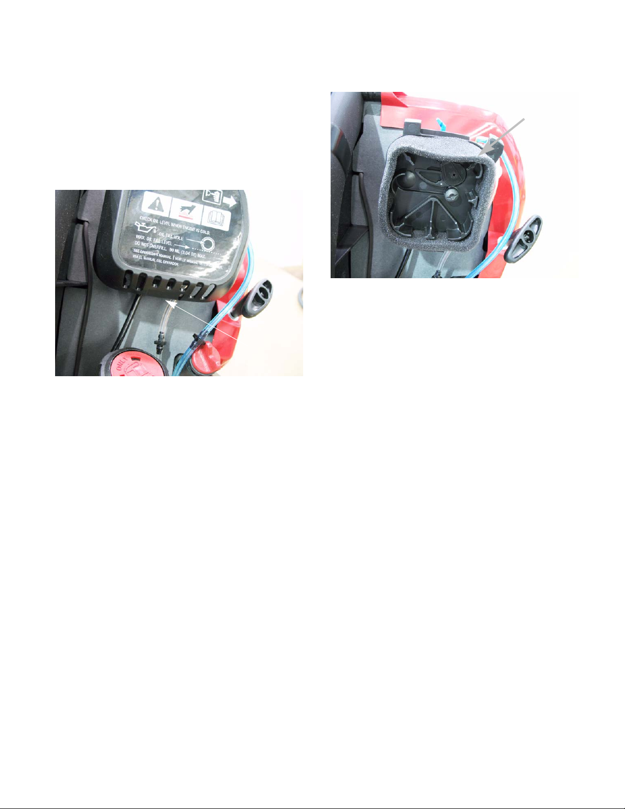
5. Inspect and clean the vent under the primer
body for debris. See Figure 5.8.
Vent
Figure 5.8
6. If the carburetor is running lean:
• Inspect the carburetor spacer for cracks.
• Inspect the spacer gasket.
7. Inspect the throttle valve assemble for debris
and freedom of movement. See Figure 5.10.
Throttle valve assembly
Figure 5.10
8. If there is a problem with the throttle valve
assembly , check on availability and price of p arts
to determine if the carburetor should be repaired
or replaced.
NOTE: A cracked spacer or a leaking gasket
between the spacer and the cylinder could result
in a lean run or prevent the impulses from the
engine from driving the fuel pump. To remove
the spacer, remove the three screws with a T-25
torx driver and swing the spacer with the heat
shied away. See Figure 5.9.
Spacer
Figure 5.9
Disassembly of the carburetor
1. Remove the for screws in the carburetor.
2. Inspect the diaphragms. If torn, damaged or brittle install a diaphragm kit.
3. Inspect for dirt or varnish bu ild up inside the c arburetor. If there is a lot of dirt/varnish in the carburetor, replace it.
4. Check that the needle valve is set to the right
height. See the carburetor manuf acturer for the
proper procedure.
5. Inspect the needle valve and seat.
6. If the seat is damaged, replace the carburetor.
NOTE: If there is a minor amount of dirt/varnish
in the carburetor or debris and/or damage to the
needle valve, install a rebuild kit.
7. To rebuild/repair a carburetor:
7a. Place the carburetor in a clean area on the
work bench.
22
Page 26

FUEL SYSTEM AND CARBURETOR
7b. Remove the four screws going thro ugh the
primer bulb housing with a #0 phillips
screwdriver.
7c. Separate the carburetor, placing each part
on the bench in the order they came
apart.
7d. Inspect the metering valve and the metering
valve seat for dirt and/or pitting.
See Figure 5.11.
Inspect for dirt
or damage
7f. Inspect the metering valve body, primer
pump body and the venturi housing for dirt
and/or varnish.
NOTE: If there is a minor amount of dirt/varnish
in the carburetor it would be worth while to clean
and rebuild the carburetor by following the procedures recommended by the carburetor manufacturer.
NOTE: If there is a lot of dirt/varnish in the carburetor, replace the carburetor.
7g. Clean the venturi and the metering valve
housings.
7h. Inspect the diaphragms for brittleness and/
or damage.
NOTE: The carburetor used in this manual is a
Walbro. Depending on the application the
engine may have a different carburetor. All carburetors have a manufacturer name cast on
them. It is advisable to contact the carburetor
manufacturer for the proper rebuild procedure.
7i. Clean the metering orifice with carb cleaner.
Figure 5.11
7e. If the metering valve seat is damaged
replace the carburetor. See Figure 5.12.
Needle valve
seat
Figure 5.12
CAUTION: Do not insert anything into the orifice
to clean it. That will damage the orifice resulting
in the carburetor being unrepairable. See Figure
5.13.
Orifice from the
Venturi side
Figure 5.13
23
Page 27

FUEL SYSTEM AND CARBURETOR
7j. The fuel pump in the carburetor is driven by
vacuum pulses in the intake port. The
impulse port from the spacer lets the vacuum pulses into the pump chamber.
See Figure 5.14.
Impulse port
Figure 5.14
7k. Make sure this port is clean and free of
debris.
7m. There are ports in the metering valve body.
it is important to make sure they are clean
and free of debris.
7n. Follow steps in reverse order to rebuild the
carburetor.
8. Perform a needle valve pop off test by following
the carburetor manufacturer’s recommendations.
9. Install the carburetor on the engine.
10. Test run the engine befo re returning it to service.
7l. Set the needle valve lever as per the carbu-
retor manufacturer’s recommendations
using a W-tool. See Figure 5.15.
Needle valve lever
Figure 5.15
24
Page 28

CHAPTER 6: BLOWER HOUSING
Blower housing
Back pack frame
1. Remove the four nuts that hold the back pack
frame to the shock mounts. See Figure 6.1.
Shock mounts
Figure 6.1
2. Remove the eight screws grip.
3. Carefully separate the grip housings, keeping
the switch and trigger in place. See Figure 6.2.
4. Remove the grip housings from the blower tube.
NOTE: Put the two grip housings back together
and secure with a couple of screws to keep the
switch, trigger, wires and cable in place while
working on the blower.
5. Slide back pack off of the blower.
NOTE: If the throttle cable is wire tied to the
back pack mount, cut the wire tie.
Figure 6.2
25
Page 29

Blower housing
Blower housing and impeller
1. Remove the nine screws that hold the blower
housing together with a T-25 torx driver. See
Figure 6.3.
Remove the
screws in the
housing
Figure 6.3
2. Lift the blower cover off.
4. Lift the impeller off of the flywheel.
NOTE: Inspect the impeller for any signs of
cracks or damage. Replace if any is found. A
damaged or cracked impeller will turn into shrapnel when the blower is running.
5. Remove the lower blower housing by removing
the four screws with a T-25 torx driver.
See Figure 6.5.
Remove these four screws
3. Remove the impeller:
3a. Remove the spark plug.
3b. Stuff a length of starter rope in the spark
plug hole to block the piston.
3c. Remove the four screws that fasten the
impeller to the flywheel. See Figure 6.4.
Remove these screws
Figure 6.4
Figure 6.5
6. Reassemble by following the previous steps in
reverse order.
NOTE: Tighten the impeller screws to a torque
of 65 - 70 lbs (7.5 - 8 Nm).
7. Test run the blower before returning to service.
26
 Loading...