

Page 1

Owner’s Manual
♦SET-UP ♦OPERATION ♦MAINTENANCE
IMPORTANT: Read Safety Rules and Instructions Carefully
PRINTED IN CANADA OGRM-7004
Page 2
CALLING CUSTOMER SUPPORT
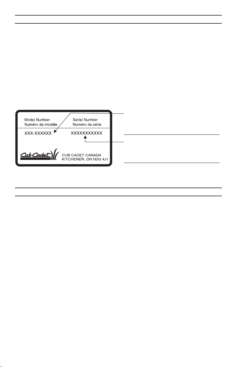
LOCATE YOUR MODEL NUMBER AND SERIAL NUMBER which appears on your unit
•
and record the information in the space provided below.
IMPORTANT: You must have these numbers, along with the date and proof of
purchase to receive warranty or service.
If you are having difficulty assembling this product or if you have any questions regard
•
ing the controls, operation or maintenance of this unit, please call an authorized dealer.
Please have your model number and serial number ready when you call.
•
NOTE: Although both numbers are important, you will be asked to enter only your serial
•
number before your call can be processed.
This is where your model number will be,
record model number here:
This is where your serial number will be,
record serial number here:
TABLE OF CONTENTS
-
CALLING CUSTOMER SUPPORT .......................................2
TABLE OF CONTENTS ..............................................2
IMPORTANT SAFE OPÉRATION PRACTICES ..............................3
SLOPE GAUGE ....................................................7
TRACTOR SET-UP..................................................8
CONTROLS .....................................................10
OPERATION .....................................................12
OPERATING THE LAWN TRACTOR ....................................13
ADJUSTMENT ...................................................14
LUBRICATION ...................................................18
MAINTENANCE ...................................................18
OFF-SEASON STORAGE ...........................................24
ATTACHMENTS & ACCESSORIES .....................................25
TROUBLE SHOOTING GUIDE ........................................26
WARRANTY......................................................27
REPLACEMENT PARTS .............................................28
2
Page 3

This unit has been inspected against the manufacturers quality check list. In case of a discrep
ancy, please call us. We will make every effort to ship the part(s) by courier within one working
day of your call.
IMPORTANT SAFE OPERATION PRACTICES
WARNING: This symbol points out important safety instructions which, if not
followed, could endanger the personal safety and/or property of yourself and
others. Read and follow all instructions in this manual before attempting to operate
this machine. Failure to comply with these instructions may result in personal
injury. When you see this symbol— heed its warning.
DANGER: This machine was built to be operated according to the rules for safe
operation in this manual. As with any type of power equipment, carelessness or
error on the part of the operator can result in serious injury. This machine is
capable of amputating hands and feet and throwing objects. Failure to observe the
following safety instructions could result in serious injury or death.
-
GENERAL OPERATION
Read, understand, and follow all instruc
•
tions on the machine and in the manual(s)
before attempting to assemble and oper
ate. Keep this manual in a safe place for
future and regular reference and for order
ing replacement parts.
Be familiar with all controls and their
•
proper operation. Know how to stop the
machine and disengage them quickly.
Never allow children under 14 years old to
•
operate this machine. Children 14 years
old and over should read and understand
the operation instructions and safety rules
in this manual and should be trained and
supervised by a parent.
•
Never allow adults to operate this machine
without proper instruction.
•
To help avoid blade contact or a thrown
object injury, keep bystanders, helpers,
children and pets at least 75 feet from the
machine while it is in operation. Stop ma
chine if anyone enters the area.
•
Thoroughly inspect the area where the
equipment is to be used. Remove all
stones, sticks, wire, bones, toys, and other
foreign objects which could be picked up
and thrown by the blade(s). Thrown ob
jects can cause serious personal injury.
•
Plan your mowing pattern to avoid dis
charge of material toward roads,
sidewalks, bystanders and the like. Also,
avoid discharging material against a wall
or obstruction which may cause dis
charged material to ricochet back toward
the operator.
•
Always wear safety glasses or safety gog
gles during operation and while performing
an adjustment or repair to protect your
eyes. Thrown objects which ricochet can
cause serious injury to the eyes.
Wear sturdy, rough-soled work shoes and
•
-
close-fitting slacks and shirts. Loose fitting
clothes and jewelry can be caught in mov
-
able parts. Never operate this machine in
bare feet or sandals.
Be aware of the mower and attachment
•
discharge direction and do not point it at
anyone. Do not operate the mower without
the discharge cover or entire grass catcher
in its proper place.
•
Do not put hands or feet near rotating
parts or under the cutting deck. Contact
with the blade(s) can amputate hands and
feet.
•
A missing or damaged discharge cover
can cause blade contact or thrown object
injuries.
•
Stop the blade(s) when crossing gravel
drives, walks, or roads and while not cut
-
ting grass.
•
Watch for traffic when operating near or
crossing roadways. This machine is not in
tended for use on any public roadway.
•
Do not operate the machine while under
the influence of alcohol or drugs.
-
•
Mow only in daylight or good artificial light.
•
Never carry passengers.
-
•
Disengage blade(s) before shifting into re
verse. Back up slowly. Always look down
and behind before and while backing to
avoid a back-over accident.
-
•
Slow down before turning. Operate the
machine smoothly. Avoid erratic operation
and excessive speed.
-
3
-
-
-
-
Page 4

Disengage blade(s), set parking brake,
•
stop engine and wait until the blade(s)
come to a complete stop before removing
grass catcher, emptying grass, unclogging
chute, removing any grass or debris, or
making any adjustments.
Never leave a running machine unat
•
tended. Always turn off blade(s), place
transmission in neutral, set parking brake,
stop engine and remove key before dis
mounting.
Use extra care when loading or unloading
•
the machine into a trailer or truck. This unit
should not be driven up or down ramp(s),
because the unit could tip over, causing
serious personal injury. The unit must be
pushed manually on ramp(s) to load or un
load properly.
Muffler and engine become hot and can
•
cause a burn. Do not touch.
Check overhead clearances carefully be
•
fore driving under low hanging tree
branches, wires, door openings etc.,
where the operator may be struck or
pulled from the unit, which could result in
serious injury.
Disengage all attachment clutches, de-
•
press the brake pedal completely and shift
into neutral before attempting to start engine.
•
Your machine is designed to cut normal
residential grass of a height no more than
10”. Do not attempt to mow through unusually tall, dry grass (e.g., pasture) or
piles of dry leaves. Dry grass or leaves
may contact the engine exhaust and/or
build up on the mower deck presenting a
potential fire hazard.
•
Use only accessories and attachments ap
proved for this machine by the machine
manufacturer. Read, understand and follow
all instructions provided with the approved
accessory or attachment.
•
Data indicates that operators, age 60 years
and above, are involved in a large percent
age of riding mower-related injuries. These
operators should evaluate their ability to
operate the riding mower safely enough to
protect themselves and others from seri
ous injury.
•
If situations occur which are not covered in
this manual, use care and good judgment.
Contact customer assistance.
SLOPE OPERATION
Slopes are a major factor related to loss of
•
control and tip-over accidents which can
result in severe injury or death. All slopes
require extra caution. If you cannot back
up the slope or if you feel uneasy on it, do
not mow it.
For your safety, use the slope gauge in
•
cluded as part of this manual to measure
-
slopes before operating this unit on a
sloped or hilly area. If the slope is greater
than 15 degrees as shown on the slope
gauge, do not operate this unit on that
area or serious injury could result.
DO:
Mow up and down slopes, not across. Ex
•
ercise extreme caution when changing
direction on slopes.
Watch for holes, ruts, bumps, rocks, or
•
other hidden objects. Uneven terrain could
overturn the machine. Tall grass can hide
obstacles.
Use slow speed. Choose a low enough
•
speed setting so that you will not have to
stop or shift while on the slope. Tires may
lose traction on slopes even though the
brakes are functioning properly. Always
keep machine in gear when going down
slopes to take advantage of engine braking action.
•
Follow the manufacturer’s recommendations for wheel weights or counterweights
to improve stability.
•
Use extra care with grass catchers or other
attachments. These can change the stabil
ity of the machine.
•
Keep all movement on the slopes slow and
gradual. Do not make sudden changes in
speed or direction. Rapid engagement or
braking could cause the front of the ma
chine to lift and rapidly flip over backwards
which could cause serious injury.
•
Avoid starting or stopping on a slope. If
tires lose traction, disengage the blade(s)
and proceed slowly straight down the
slope.
DO NOT:
-
•
Do not turn on slopes unless necessary;
then, turn slowly and gradually downhill, if
possible.
•
Do not mow near drop-offs, ditches or em
bankments. The mower could suddenly
turn over if a wheel is over the edge of a
cliff, ditch, or if an edge caves in.
-
-
-
-
-
4
Page 5

Do not try to stabilize the machine by putt
•
ing your foot on the ground.
Do not use a grass catcher on steep
•
slopes.
Do not mow on wet grass. Reduced trac
•
tion could cause sliding.
Do not shift to neutral and coast downhill.
•
Over-speeding may cause the operator to
lose control of the machine resulting in se
rious injury or death.
Do not tow heavy pull behind attachments
•
(e.g. loaded dump cart, lawn roller, etc.)
on slopes greater than 5 degrees. When
going down hill, the extra weight tends to
push the tractor and may cause you to
loose control. (e.g. tractor may speed up,
braking and steering ability are reduced,
attachment may jack-knife and cause trac
tor to overturn).
CHILDREN
Tragic accidents can occur if the operator
•
is not alert to the presence of children.
Children are often attracted to the machine
and the mowing activity. They do not understand the dangers. Never assume that
children will remain where you last saw
them.
a. Keep children out of the mowing area
and in watchful care of a responsible
adult other than the operator.
b. Be alert and turn machine off if a child
enters the area.
c. Before and while backing, look behind
and down for small children.
d. Never carry children, even with the
blade(s) shut off. They may fall off and
be seriously injured or interfere with
safe machine operation.
e. Use extreme care when approaching
blind corners, doorways, shrubs, trees
or other objects that may block your vi
sion of a child who may run into the
machine.
f. Disengage the cutting blade(s) before
shifting in reverse. The “No-Cut-In Re
verse” feature is a reminder not to cut
in reverse and to help avoid back over
accidents. Do not defeat it.
g. Keep children away from hot or run
ning engines. They can suffer burns
from a hot muffler.
h. Remove key when machine is unat
tended to prevent unauthorized
operation.
Never allow children under 14 years old to
-
•
operate the machine. Children 14 years
old and over should read and understand
the operation instructions and safety rules
in this manual and should be trained and
-
supervised by a parent.
TOWING
Tow only with a machine that has a hitch
•
designed for towing. Do not attach towed
equipment except at the hitch point.
Follow the manufacturers recommendation
•
for weight limits for towed equipment and
towing on slopes.
Never allow children or others in or on
•
towed equipment.
On slopes, the weight of the towed equip
•
ment may cause loss of traction and loss
of control.
Travel slowly and allow extra distance to
•
stop.
Do not shift to neutral and coast downhill.
•
SERVICE
SAFE HANDLING OF GASOLINE:
To avoid personal injury or property
•
damage use extreme care in handling gasoline. Gasoline is extremely flammable
and the vapors are explosive. Serious personal injury can occur when gasoline is
spilled on yourself or your clothes which
can ignite. Wash your skin and change
clothes immediately.
a. Use only an approved gasoline con
tainer.
b. Never fill containers inside a vehicle or
on a truck or trailer bed with a plastic
liner. Always place containers on the
ground away from your vehicle before
filling.
c. When practical, remove gas-powered
-
equipment from the truck or trailer and
refuel it on the ground. If this is not
possible, then refuel such equipment
on a trailer with a portable container,
-
rather than from a gasoline dispenser
nozzle.
d. Keep the nozzle in contact with the rim
of the fuel tank or container opening at
-
all times until fueling is complete. Do
not use a nozzle lock-open device.
e. Extinguish all cigarettes, cigars, pipes
-
and other sources of ignition.
f. Never fuel machine indoors.
g. Never remove gas cap or add fuel
while the engine is hot or running. Al
5
-
-
-
Page 6

low engine to cool at least two minutes
before refueling.
h. Never over fill fuel tank. Fill tank to no
more than ½ inch below bottom of filler
neck to allow space for fuel expansion.
i. Replace gasoline cap and tighten se
curely.
j. If gasoline is spilled, wipe it off the en
gine and equipment. Move unit to
another area. Wait 5 minutes before
starting the engine.
k. To reduce fire hazards, keep machine
free of grass, leaves, or other debris
build-up. Clean up oil or fuel spillage
and remove any fuel soaked debris.
l. Never store the machine or fuel con
tainer inside where there is an open
flame, spark or pilot light as on a water
heater, space heater, furnace, clothes
dryer or other gas appliances.
m. Allow a machine to cool at least 5
minutes before storing.
GENERAL SERVICE:
Never run an engine indoors or in a poorly
•
ventilated area. Engine exhaust contains
carbon monoxide, an odorless, and deadly
gas.
• Before cleaning, repairing, or inspecting,
make certain the blade(s) and all moving
parts have stopped. Disconnect the spark
plug wire and ground against the engine
to prevent unintended starting.
•
Periodically check to make sure the blades
come to complete stop within approxi
mately (5) five seconds after operating the
blade disengagement control. If the blades
do not stop within the this time frame, your
unit should be serviced professionally by
an authorized Service Dealer.
•
Check brake operation frequently as it is
subjected to wear during normal operation.
Adjust and service as required.
•
Check the blade(s) and engine mounting
bolts at frequent intervals for proper tight
ness. Also, visually inspect blade(s) for
damage (e.g., excessive wear, bent,
cracked).
Replace the blade(s) with the original
•
equipment manufacturer’s (O.E.M.)
blade(s) only, listed in this manual. “Use of
parts which do not meet the original equip
ment specifications may lead to improper
performance and compromise safety!”
Mower blades are sharp. Wrap the blade
•
or wear gloves, and use extra caution
when servicing them.
Keep all nuts, bolts, and screws tight to be
•
sure the equipment is in safe working con
dition.
Never tamper with the safety interlock sys
•
tem or other safety devices. Check their
proper operation regularly.
-
After striking a foreign object, stop the en
•
gine, disconnect the spark plug wire(s)
and ground against the engine. Thor
oughly inspect the machine for any
damage. Repair the damage before start
ing and operating.
Never attempt to make adjustments or re
•
pairs to the machine while the engine is
running.
Grass catcher components and the dis-
•
charge cover are subject to wear and
damage which could expose moving parts
or allow objects to be thrown. For safety
protection, frequently check components
and replace immediately with original
equipment manufacturer’s (O.E.M.) parts
only, listed in this manual. “Use of parts
which do not meet the original equipment
specifications may lead to improper perfor
-
mance and compromise safety!”
•
Do not change the engine governor set
tings or over-speed the engine. The
governor controls the maximum safe oper
ating speed of the engine.
•
Maintain or replace safety and instruction
labels, as necessary.
•
Observe proper disposal laws and regula
tions for gas, oil, etc. to protect the
environment.
-
-
-
-
-
-
-
-
-
-
-
-
6
Page 7
OWNER'S
MANUAL
SAFETY LABEL
WARNING - Your Responsibility:
Restrict the use of this power machine to persons who
read, understand and follow the warnings and instruc
tions in this manual and on the machine.
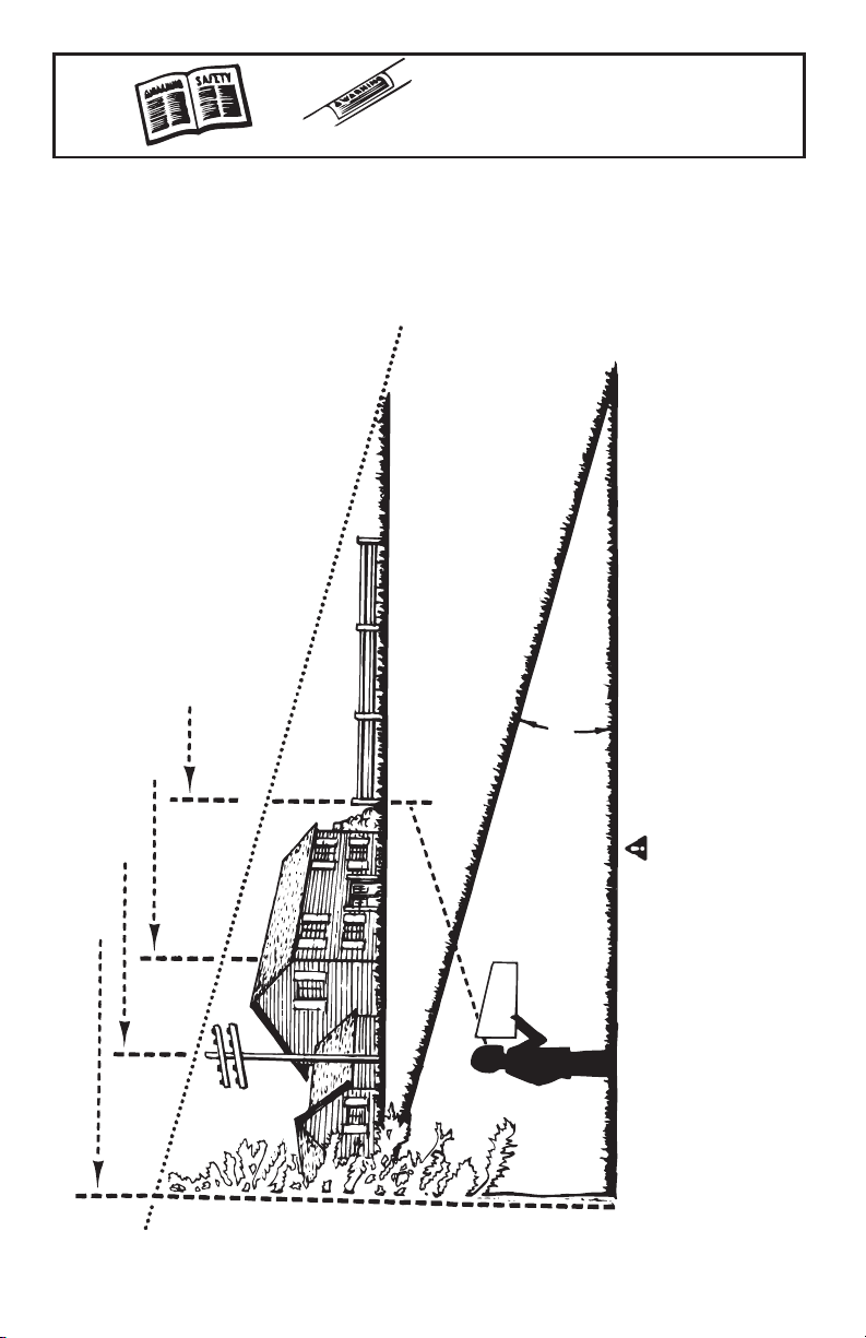
SLOPE GAUGE
SLOPE
o
OR A FENCE POST
-
SIGHT AND HOLD THIS LEVEL WITH A VERTICAL TREE
USE THIS SHEET AS A GUIDE TO DETERMINE SLOPES WHERE YOU MAY NOT OPERATE SAFELY.
A CORNER OF A BUILDING
A POWER POLE
FOLD ON DOTTED LINE, REPRESENTING A 15
15º
DANGER
Do not mow on inclines with a slope in excess excess of 15 degrees ( a rise of approximately 2½ feet every
10 feet). A riding mower could overturn and cause serious injury. If operating a walk-behind mower on such a
slope, it is extremely difficult to maintain your footing and you could slip, resulting in serious injury.
Operate RIDING mowers up and down slopes, never across the face of slopes.
Operate WALK-BEHIND mowers across the face of slopes, never up and down slopes.
7
Page 8
This owner’s manual covers various models of
lawn tractors. The units illustrated may vary
slightly from your unit. Follow only those in
structions which pertain to your model lawn
tractor.
IMPORTANT: This unit is shipped WITHOUT
GASOLINE. Check oil before starting en
gine. Do not overfill. After assembly, service
engine with gasoline and oil as instructed
in the separate engine manual packed with
your unit.
NOTE: Reference to right or left hand
side of the unit is observed from the
driver’s seat, facing forward.
Tools Required For Assembly
(1) ½" socket wrench (for steering wheel)
(1) 9/16" wrench or socket wrench (for seat)
(2) 7/16 wrenches or socket wrenches
(for battery)
TRACTOR SET-UP
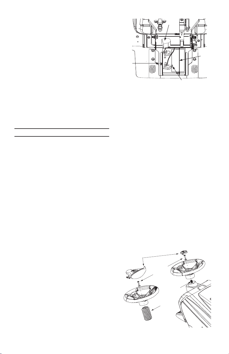
ATTACHING THE BATTERY CABLES
NOTE: The positive battery terminal is
marked Pos. (+). The negative battery
terminal is marked Neg. (–).
The positive cable (heavy red wire) is se-
•
cured to the positive battery terminal (+)
with a hex bolt and hex nut at the factory.
Make certain that the rubber boot covers the
terminal to help protect it from corrosion.
•
Remove the hex bolt and hex nut from the
negative cable.
•
Remove the black plastic cover, if present,
from the negative battery terminal and attach
the negative cable (heavy black wire) to the
negative battery terminal (–) with the bolt
and hex nut.
•
Make certain the hold-down rod is in posi
tion over the battery, securing it in place.
See Figure 1.
CHARGING THE BATTERY
If battery is put into service after date shown
on top of battery, charge the battery with a
battery charger before using your unit. A
charger with an output of six amps should
be used and the battery should be charged
for one hour. This charging will help extend
the life of the battery.
If a charger with a six amp output is not
available, a lower output charger may be
used for a longer period of time. Do not
charge the battery at a rate higher than six
amps as it can damage the battery and re
duce its useful life.
Rubber
-
Boot
-
Hex
Nut
FIGURE 1
Hex Bolt
If a charger is not available but the battery
will start the lawn tractor, the battery can be
charged by mowing for a minimum of one
hour using the engine’s charging system.
The lawn tractor should be ran at full throttle
during this process.
NOTE: More than one hour of mowing
may be needed to fully charge the bat
tery since the output of the engine’s
charging system is typically less than
six amps.
ATTACHING THE STEERING WHEEL
The hardware for attaching the steering
•
wheel is located under the steering wheel
cap. Carefully pry off the steering wheel cap
and remove the hardware.
NOTE: There are two different styles of
steering wheel caps. See Figure 2.
Styles vary by model.
•
Remove the steering bellow (not required
on all models) from the lift lever on the
right hand side of lawn tractor. Place steer
ing bellow over the steering shaft
extending through the dash.
-
Steering Wheel
Cap/Insert
Hex Bolt
and
Washer
Steering
Shaft
Steering
Bellow
-
FIGURE 2
8
HoldDown
Rod
-
-
Page 9
NOTE: If the openings on each end of
the steering bellow are two different
sizes, the smaller end goes down
against the dash of the lawn tractor.
Position the front wheels of the tractor so
•
they are pointing straight forward.
Place the steering wheel over the steering
•
shaft, positioning steering wheel as de
sired.
Place the washer
•
with the cupped
side down over
the steering shaft.
Crowned
Side
Cupped
Side
Secure with hex
bolt. See Figure 2.
Place the steering wheel cap over the
•
center of the steering wheel and seat it
with your hand. See Figure 2.
If your unit is equipped with a steering in
•
sert packed in a plastic bag with the
literature, snap it over the round steering
wheel cap. See Figure 2.
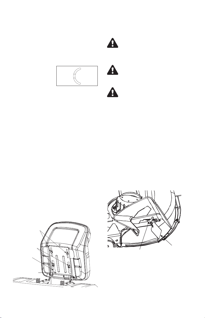
ATTACHING THE SEAT
For shipping reasons, seats are either fastened to the tractor seat’s pivot bracket with
a plastic tie, or mounted backward to the
pivot bracket. In either case, free the seat
form its shipping position and remove the
two hex screws (or knobs, on models so
equipped) from the bottom of seat before
proceeding with instructions below.
•
Position the shoulder screws (found on the
base of the seat) inside the slot openings
in the seat pivot bracket.
•
Slide the seat slightly rearward in the seat
pivot bracket, lining up the rear slots in the
pivot bracket with the remaining two holes
in the seat’s base.
Select desired position for the seat, and
•
secure with the two hex screws/knobs re
moved. Do not overtighten. See Figure 3.
Shipping Brace Removal
WARNING: Make sure the tractor’s
engine is off, remove the key from
the ignition switch and apply the
-
tractor’s parking brake before
removing the shipping brace.
WARNING: The shipping brace,
used for packaging purposes only,
must be removed and discarded
before operating your riding mower.
WARNING: The mowing deck is
capable of throwing objects. Failure
to operate the tractor without the
discharge chute properly in place
could result in serious personal
-
injury and/or property damage.
Locate the shipping brace and accompa
•
nying warning tag on the right side of the
mower, between the discharge chute and
the cutting deck. See Figure 4.
While holding the discharge chute with
•
your left hand, remove the shipping brace
with your right hand by grasping it between your thumb and index finger and
rotating it clockwise.
•
Carefully allow the discharge chute to pivot
downward. See Figure 4.
•
Discard the shipping brace and accompanying warning tag.
-
-
Hex Screws
(optional knobs)
Shoulder
Opening in
Slot
Pivot
Bracket
FIGURE 3
Shipping Brace
Warning Tag
FIGURE 4
INSTALLING THE MULCHING PLUG
(optional)
•
Locate the square hole found in the cutting
deck surface by pivoting the discharge
chute upward.
9
Page 10

Carriage Bolt
Cupped
Washer
Discharge Chute in
Proper Operating Position
FIGURE 5
Install the mulch plug and secure it in
•
place with the carriage bolt, cupped
washer and plastic wing nut as illustrated
in Figure 6.
Remove the mulching plug for standard
•
side discharge mowing. See Figure 5.
TIRE PRESSURE
For shipping purposes, the tires on your unit
may be over inflated. Tire pressure should
be reduced before unit is put into operation.
Recommended operating tire pressure
should be 12 p.s.i.
Check sidewall of tire for manufacturer’s
maximum tire pressure. If this information
does not appear on your tire, maximum tire
pressure under any circumstances is 30
p.s.i. Equal tire pressure should be maintained on all tires.
FINAL ASSEMBLY
Make certain all nuts and bolts are tightened
securely.
CONTROLS
IGNITION SWITCH
The ignition switch is located on the right
side of the tractor’s dash. To start the en
gine, insert the key into the ignition switch
and turn clockwise to the START position.
Release the key into the ON position once
engine has fired. See Figure 7 .
Refer to Starting The Engine in the Operation
section of this manual for detailed starting in
structions.
Never leave a running machine
unattended. Always disengaged
PTO, shift into neutral, set parking
brake, stop engine and remove key
to prevent unintended starting.
Wing
nut
FIGURE 6
CHOKE CONTROL
On some models, moving the
throttle lever all the way forward
activates the engine’s choke
control. On all other models the
choke control can be found on
the left side of the dash panel and is acti
vated by pulling the knob outward.
Activating the choke control closes the
choke plate on the carburetor and aids in
starting the engine. Refer to “Starting the Engine”.
THROTTLE CONTROL
LEVER
The throttle lever is located on the left side of
the dash panel. This lever controls the speed of
the engine, and on some
models, when pushed all
the way forward, the
choke control also.
When set in a given po
sition, the throttle will
maintain a uniform en
gine speed.
IMPORTANT: When op
erating the tractor with the cutting deck
-
engaged, be certain that the throttle lever is
always in the FAST (rabbit) position.
DECK ENGAGEMENT / LIFT LEVER
Found on the right side of the tractor, the
deck engagement/lift lever is used to set the
-
mowing deck’s cutting height and engage
the power to the cutting deck or other (sepa
rately available) attachments. To operate,
move the lever to the right and forward, be
fore placing it a notch for your desired
cutting height. Moving the lever to the right
and all the way rearward placing it into the
BLADES STOP position disengages power
to the cutting deck/ attachment.
10
Mulching Plug
Choke
Position
Fast
Position
-
Slow
Position
-
-
-
-
-
Page 11

H
A
B
C
FIGURE 7
A - Clutch-brake Pedal
B - Choke Control
C - Throttle Control Lever
D - Deck engagement/
D
E
F
Lift Lever (PTO)
E - Ignition Switch
F - Shift Lever
G - Speed Control
Lever/Parking Brake
H - Seat Adjustment Lever
G
(optional)
NOTE: The deck engagement/lift le
ver must be in the disengaged
(BLADES STOP) position when starting the engine, when traveling in
reverse and if the operator leaves the
seat.
PARKING BRAKE
To set the parking brake,
fully depress the
clutch-brake pedal. Move
the speed control lever
all the way to the rear
and release it into the
parking brake position.
Release the clutch-brake
pedal to allow the park
-
6
5
4
3
2
1
ing brake to engage.
To release the parking
brake, depress the
P
clutch-brake pedal and
move the speed control
lever out of the notches
to the desired position. Release the speed
control lever and the clutch-brake pedal.
NOTE: The parking brake must be set if the
operator leaves the seat with the engine
running or the engine will automatically
shut off.
IMPORTANT: Always set the parking
brake when leaving the tractor unattended.
SHIFT LEVER
The shift lever is located in the center of
the console and has
F
N
R
three positions, F
(Forward), N (Neutral) and R (Reverse).
The clutch-brake
pedal must be fully
Shift
Knob
depressed and the
tractor must not be in
motion when the moving shift lever.
IMPORTANT: Never force the shift lever.
Doing so may result in serious damage to
the tractor’s transmission.
NOTE: If difficulty is encountered while at
tempting to shift, release the clutch-brake
pedal slightly before fully depressing the
pedal again.
SPEED CONTROL LEVER
The speed control lever, located on the
right side of the center console, allows you
to regulate the ground speed of the lawn
tractor. To use, depress the clutch-brake
pedal and move the lever out of the parking
brake notch and forward to increase the
tractor’s ground speed. When a desired
speed has been reached, release the lever
into an appropriate notch to maintain that
speed.
To slow the tractor’s ground speed, de
press the clutch-brake pedal and move the
speed control lever rearward and release it
into a notch.
-
-
11
Page 12

SAFETY INTERLOCK SYSTEM
WARNING: Read, understand, and
follow all instructions and warnings
on the machine and in this manual
before operating.
This tractor is equipped with a safety inter
lock system for the protection of the
operator. If the interlock system should ever
malfunction, do not operate the tractor. Con
tact an authorized service dealer. The safety
interlock system prevents the engine from
cranking or starting unless the parking brake
is engaged, and the deck engagement/lift le
ver is in the disengaged (BLADES STOP)
position.
The engine will automatically shut off if the
•
operator leaves the seat before engaging
the parking brake.
The engine will automatically shut off if the
•
operator leaves the tractor’s seat with the
deck engagement/ lift lever in ANY position
other than BLADES STOP.
The engine will automatically shut off if the
•
deck engagement/lift lever is moved out of
the BLADES STOP position with the speed
control lever in position for reverse travel.
OPERATION
BEFORE STARTING ENGINE
WARNING: Read, understand, and
follow all instructions and warnings
on the machine and in this manual
before operating.
•
Service the engine with oil and gasoline as
described in the engine manual.
•
Depress the clutch-brake pedal and set the
parking brake.
•
Place the deck engagement/lift lever in the
DISENGAGED (BLADES STOP) position.
STARTING THE ENGINE
WARNING: Do not operate the lawn
tractor if the interlock system is
malfunctioning because it is a
safety device, designed for
protection.
NOTE: To open the hood simply lift up
on both sides of the hood.
•
Insert the tractor key into the ignition
switch.
•
Activate the choke control (a warm engine
may not require choking).
WARNING
GO UP AND DOWN SLOPES NOT ACROSS -
•
AVOID SUDDEN TURNS.
-
-
-
AVOID SERIOUS INJURY OR DEATH.
•
DO NOT OPERATE THE UNIT WHERE IT
•
COULD SLIP OR TIP
IF MACHINE STOPS GOING UPHILL, STOP
•
.
BLADE(S) AND BACK DOWNHILL SLOWLY.
DO NOT MOW WHEN CHILDREN OR OTHERS
•
ARE AROUND
NEVER CARRY CHILDREN.
•
LOOK DOWN AND BEHIND BEFORE AND
•
.
WHILE BACKING.
KEEP SAFETY DEVICES (GUARDS, SHIELDS,
•
AND SWITCHES) IN PLACE AND WORKING.
REMOVE OBJECTS THAT COULD BE THROWN
•
BY THE BLADE(S).
KNOW LOCATION AND FUNCTION OF ALL
•
CONTROLS
BE SURE BLADE(S) AND ENGINE ARE
•
.
STOPPED BEFORE PLACING HANDS OR FEET
NEAR BLADE(S)
BEFORE LEAVING OPERATOR’S POSITION,
•
.
DISENGAGE BLADE(S), PLACE THE SHIFT
LEVER IN NEUTRAL, ENGAGE BRAKE LOCK,
SHUT ENGINE OFF AND REMOVE KEY.
READ OPERATOR’S MANUALS.
•
Turn the ignition key clockwise to the
START position. After the engine starts, re
lease the key. It will return to the ON
position.
IMPORTANT: Do NOT hold the key in the
START position for longer than ten seconds
at a time. Doing so may cause damage to
your engine’s electric starter.
•
After the engine starts, deactivate the
choke control and place the throttle control
in the FAST position.
IMPORTANT: Do NOT leave the choke con
trol on while operating the tractor. Doing so
will result in a “rich” fuel mixture and cause
the engine to run poorly.
STOPPING THE ENGINE
WARNING: If you strike a foreign
object, stop the engine. Remove
wire from spark plug, thoroughly
inspect the unit for any damage,
and repair the damage before
restarting and operating the mower.
-
-
12
Page 13

NOTE: If any problems are encoun
tered, refer to the Trouble Shooting
Chart.
If the blades are engaged, place the deck
•
engagement/lift lever in the BLADES STOP
position.
Depress the clutch-brake pedal to bring the
•
tractor to a complete stop.
Turn the ignition key counterclockwise to the
•
OFF position.
Engage the tractor’s parking brake.
•
Remove the key from the ignition switch to
•
prevent unintended starting.
OPERATING THE LAWN TRACTOR
WARNING: Always look down and
behind before and while backing up
to avoid a back-over accident.
WARNING: Before leaving the
operator’s position. Always place the
deck engagement/ lift lever in the
BLADES STOP position, shift into
neutral, set parking brake, stop
engine and remove key to prevent
unintended starting.
• Move throttle control lever to full throttle.
NOTE: Always operate the tractor with the
throttle control lever in the FAST (rabbit) position for the most efficient use of the cutting
deck or other (separately available) attachments.
•
Place the shift lever in either the FORWARD
or REVERSE position.
•
Release the parking brake by depressing
the clutch-brake pedal and positioning the
speed control lever in desired position.
IMPORTANT: First-time operators should use
slower speeds. Become completely familiar
with the tractor’s operation and controls be
fore operating the tractor in at higher speed
positions.
•
Release clutch-brake pedal slowly to put
unit into motion.
•
The lawn tractor is brought to a stop by de
pressing the clutch-brake pedal.
NOTE: When operating the unit initially,
there will be little difference between
the highest two speeds until after the
belts have seated themselves into the
pulleys during the break-in period.
WARNING: Before leaving the
operator’s position for any reason,
disengage the blades, place the
speed control lever in neutral,
engage the parking brake, shut
engine off and remove the key.
IMPORTANT: When stopping the tractor for
any reason while on a grass surface, always:
Place the shift lever in neutral.
•
Engage the parking brake,
•
Shut engine off and remove the key.
•
Doing so will minimize the possibility of having
your lawn ‘‘browned’’ by hot exhaust from
your tractor’s running engine.
If unit stalls with speed control in high speed,
or if unit will not operate with speed control le
ver in a low speed position, proceed as
follows.
Place shift lever in NEUTRAL.
•
Restart engine.
•
Place speed control lever in high speed po
•
sition.
Release clutch-brake pedal fully.
•
Depress clutch-brake pedal.
•
Place speed control lever in desired posi-
•
tion.
•
Place shift lever in either FORWARD or REVERSE, and follow normal operating
procedures.
ENGAGING THE CUTTING BLADES
WARNING: Keep feet and hands
away from the discharge opening, the
blades or any part of the deck. When
the unit is used for anything other
than mowing operations, the blade
drive should be disengaged.
To engage power to the cutting deck or other
(separately available) attachment, proceed as
follows:
•
Move the deck engagement/lift lever to the
right and forward.
•
Place the lever a notch for your desired cut
ting height.
-
•
Moving the lever to the right and all the way
rearward placing it into the BLADES STOP
position raises and disengages power to the
cutting deck.
NOTE: The deck engagement/lift lever
must be in the disengaged (BLADES
STOP) position when starting the en
gine, when traveling in reverse and if
the operator leaves the seat.
13
-
-
-
-
Page 14

MOWING
WARNING: To help avoid blade
contact or a thrown object injury,
keep bystanders, helpers, children
and pets at least 75 feet from the
machine while it is in operation.
Stop machine if anyone enters the
area.
The following information will be helpful
when using the cutting deck with your trac
tor.
WARNING: Plan your mowing
pattern to avoid discharge of
materials toward roads, sidewalks,
bystanders and the like. Also, avoid
discharging material against a wall
or obstruction which may cause
discharged material to ricochet
back toward the operator.
Be sure that the lawn is clear of stones,
•
sticks, wire, or other objects which could
damage lawn mower or engine.
For best results and to insure more even
•
grass distribution, do not mow when lawn
is excessively wet.
Do not mow at high ground speed, espe-
•
cially if a mulch kit or grass collector is
installed.
•
For best results it is recommended that the
first two laps be cut with the discharge
thrown towards the center. After the first
two laps, reverse the direction to throw the
discharge to the outside for the balance of
cutting. This will give a better appearance
to the lawn.
•
Do not cut the grass too short. Short grass
invites weed growth and yellows quickly in
dry weather.
•
Mowing should always be done with the
engine at full throttle.
•
Under heavier conditions it may be neces
sary to go back over the cut area a
second time to get a clean cut.
•
Do NOT attempt to mow heavy brush and
weeds and extremely tall grass. Your trac
tor is designed to mow lawns, NOT clear
brush.
•
Keep the blades sharp and replace the
blades when worn. Refer to Cutting Blades
in the Maintenance section of this manual
for proper blade sharpening instructions.
MULCHING
Some, NOT ALL, models come equipped
with a mulch kit which incorporates special
blades, already standard on your tractor, in a
process of recirculating grass clippings re
peatedly beneath the cutting deck. The
ultra-fine clippings are then forced back into
the lawn where they act as a natural fertilizer.
Observe the following points for the best re
sults when mulching.
Never attempt to mulch if the lawn is
•
damp. Wet grass tends to stick to the un
derside of the cutting deck preventing
proper mulching of the clippings.
Do NOT attempt to mulch more than 1/3
•
the total height of the grass or approxi
mately 1-1/2 inches. Doing so will cause
the clippings to clump up beneath the
deck and not be mulched effectively.
Maintain a slow ground speed to allow the
•
grass clippings more time to effectively be
mulched.
Always position the throttle control lever in
•
the FAST (rabbit) position and allow it to
remain there while mowing. Failing to keep
the engine at full throttle places strain on
the tractor’s engine and does not allow the
blades to properly mulch grass.
NOTE: It is not necessary to remove
the discharge chute to operate the
mower with the mulch kit installed.
38- and 42-inch Decks
To operate the cutting deck without mulch
ing, on models so equipped, simply remove
the mulch plug by unthreading the plastic
wing nut which fastens it to the cutting deck.
This will allow the clippings to discharge out
the side. See Figures 6 and 5.
46-inch Decks
On models so equipped, the mulch kit is
packed separately within the tractor’s crate.
-
Observe the instructions included with the
mulch kit for the best results when mulching.
ADJUSTMENT
-
SEAT ADJUSTMENT
The seat may be adjusted to one of several
positions. Refer to seat installation section of
tractor set-up instructions.
DECK LEVELING ADJUSTMENT
WARNING: Protect your hands by
wearing heavy gloves to grasp the
cutting blade.
-
-
-
-
-
14
Page 15

NOTE: Check the tractor’s tire pres
sure before performing any deck
leveling adjustments. Refer to Tires
later in this section for further informa
tion regarding tire pressure.
The front of the cutting deck is supported by
two lift links that can be adjusted to level the
deck from both front to rear & side to side.
The front of the deck should be between
1/4-inch and 3/8-inch lower than the rear of
the deck. Adjust if necessary as follows:
With the tractor parked on a firm, level sur
•
face, place the deck engagement/lift lever
in the top cutting height notch (not
BLADES STOP) position.
Rotate the blade nearest the discharge
•
chute so that it is parallel with the tractor.
Measure the distance from the front of the
•
blade tip to the ground and the rear of the
blade tip to the ground. The first measure
ment taken should be between 1/4" and
3/8" less than the second measurement.
Determine the approximate distance nec
essary for proper adjustment and proceed,
if necessary, to the next step.
Place the deck engagement/lift lever in the
•
engaged (all the way forward) position.
• Remove the hairpin clip from the ferrule
found at the bottom of the front, left deck
link (hairpin clip is on the inside of the lift
link). See Figure 8 .
•
Pull the ferrule out of the deck hanger and
thread the ferrule up or down, as necessary.
NOTE: Usually only one or two turns are
needed.
•
Insert the ferrule back into the deck hanger
and refasten with the hairpin clip removed
earlier.
•
Repeat the previous steps on the front,
right lift link
•
Check the front-to-rear adjustment by
re-measuring. Check the side-to-side ad
justment by placing a level on the deck
surface.
•
Readjust if necessary.
SETTING THE DECK WHEEL HEIGHT (on
models so equipped)
•
Select the height position of the cutting
deck by placing the Deck Engagement /
Lift Lever in any of the five different cutting
height notches on the right side of the
frame.
FIGURE 8
Adjust the deck wheels so that they are
•
Adjustable Deck Links,
Ferrules & Hairpin Clips
between 1/4-inch and ½-inch above the
ground when the tractor is on a smooth,
flat surface such as a driveway.
-
WARNING: Keep hands and feet
away from the discharge opening of
the cutting deck.
-
NOTE: The deck wheels, on models
so equipped, are an anti-scalp feature
of the deck and are not designed to
support the weight of the cutting deck.
Refer to Deck Leveling Adjustment of this
manual for more detailed instructions regarding deck adjustments.
DECK ENGAGEMENT ADJUSTMENT
WARNING: Never attempt to make
the adjustment while the engine is
running. Always shift to neutral, set
the parking brake, stop engine and
remove key to prevent unintended
starting.
The cutting deck engagement may be ad
justed to make certain the deck is
disengaged when deck engagement/lift lever
is in the BLADES STOP position. Correct ad
justment as follows.
•
With the engine off, place the deck en
-
gagement/lift lever in the BLADES OFF
position.
•
Unthread the shift knob and remove the
two flange screws which secure the shift
cover panel in place. See Figure 11.
•
Remove the cover panel and locate the
deck disengagement rod. See Figure 11.
NOTE: There is a small yellow wire
connected to a spring switch on the
underside of the cover panel. Be care
ful not to damage it when removing
the panel.
15
-
-
-
-
Page 16

Stabilizer Shaft
Assembly
Compression
Spring
Hex
Nut
Disengagement Rod
FIGURE 9
Remove the hairpin clip which secures the
•
disengagement rod to the stabilizer shaft
assembly. See Figure 10.
Pull the rod toward the rear of the tractor
•
(to take up slack), then thread the rod in
ward or outward (usually only one or two
turns) until the rod lines up as precisely as
possible with the hole in the stabilizer
shaft.
NOTE: Threading the disengagement
rod outward (toward the rear of the
tractor) provides for more belt tension.
Threading the disengagement rod inward provides for less belt tension.
•
Reinsert the ferrule and re-secure the rod
with the cotter pin removed earlier.
Check the adjustment by placing the deck
engagement/ lift lever in the BLADES STOP
position. The deck should move up and for
ward, allowing the belt to become loose.
•
Reassemble the cover panel.
•
Start the tractor’s engine and test the deck
engagement/lift lever to be certain the
blades fully disengage when in the
BLADES STOP.
•
Repeat the adjustment procedure if neces
sary.
PARKING BRAKE ADJUSTMENT
WARNING: Never attempt to adjust the
brakes while the engine is running.
Always disengage PTO, move speed
control lever into neutral position, stop
engine and remove key to prevent
unintended starting.
If the tractor does not come to a complete stop
when the brake pedal is completely depressed,
or if the tractor’s rear wheels can roll with the
parking brake applied, the brake is in need of
adjustment. The brake disc can be found on the
Transmission
FIGURE 10
R,
right side of the transmission in the rear of
the tractor. Adjust if necessary as follows:
Looking at the transmission from the right side
of the tractor, locate the compression spring and
brake disc. See Figure 10.
Loosen, but do NOT remove, the hex nut
•
found on the right side of the brake assembly.
See Figure 10.
Using a feeler gauge, set the gap between
•
the brake disc and the brake puck at .011".
Re-tighten the hex nut loosened earlier.
•
SPEED CONTROL ADJUSTMENT
NOTE: When operating the unit initially
or after replacing the belts, there will
be little difference between the highest
two speeds until after the belts have
gone through a break-in period and
-
have seated themselves into the pul
leys.
If the full range of speeds cannot be ob
tained on your unit, adjust the speed control
as follows.
•
Unthread the shift knob and remove the
two flange screws which secure the cover
panel in place. Refer to Figure 11.
-
Knob
Flange Screws
Shift Cover Panel
FIGURE 11
Brake Disc
-
-
16
Page 17

Remove the cover panel and locate the
•
speed control rod. See Figure 14.
NOTE: There is a small yellow wire con
nected to a spring switch on the underside of
the cover panel. Be careful not to damage it
when removing the panel.
Remove the hairpin clip which secures the
•
speed control rod’s ferrule to the speed
bracket. See Figure 14.
At the factory, the speed control rod is ad
justed so that 5/8-in. of the rod is exposed
beyond the ferrule.
Adjust the speed control by threading the
•
ferrule inward so that no more than 3/4-in.
of the rod is exposed beyond the ferrule.
See Figure 12.
Reinsert the ferrule and re-secure the rod
•
with the hairpin clip removed earlier.
Reassemble the cover panel, start the trac
•
tor’s engine and test the full range of
speeds.
IMPORTANT: If the above adjustment did
not result in the tractor obtaining the full
range of speeds, see an authorized service
dealer to have the variable speed drive system inspected and professionally adjusted.
STEERING ADJUSTMENT
(Units With Adjustable Tie Rod)
If the tractor turns tighter in one direction
than the other, or if either the tie rod and ferrule are being replaced due to damage or
wear, the tie rod may need to be adjusted.
To do so, proceed as follows:
NOTE: A replacement cotter pin (part no.
714-0470) is needed to complete this adjust
ment. Have one on hand before proceeding.
•
Place the steering wheel in position for
straight ahead travel.
•
In front of the pivot bar, measure the dis
tance horizontally from the inside of the left
rim to the inside of the right rim. Note the
distance.
•
Behind the pivot bar, measure the distance
horizontally from the inside of the left rim
to the inside of the right rim. Note the dis
tance.
•
The measurement taken in front of the
pivot bar should be between 1/16” and
5/16” less than the measurement taken be
hind the pivot bar. If it is not, an
adjustment is necessary. Proceed as fol
lows.
•
Locate the ferrule at the right end of the tie
rod, just to the rear of the right, front tire of
tractor. See Figure 13.
3/4"
Maximum
-
FIGURE 12
-
Tie Rod
Ferrule
Right Axle
Right Front Tire
Right Front Tire
FIGURE 13
Ferrule and
Hairpin Clip
-
Speed Control Rod
FIGURE 14
•
Remove the cotter pin and flat washer
which secures the adjustment ferrule to the
tractors right axle.
•
Two turns at a time, thread the adjustment
-
ferrule toward the right, front tire to
lengthen the tie rod. Or, thread the adjust
ment ferrule away from the right, front tire
to shorten the tie rod.
NOTE: Lengthening the tie rod increases the
tractor’s front tie toe-in. Shortening the tie
rod decreases the tractor’s front tire toe-in.
•
Reinsert the adjustment ferrule and tempo
rarily secure it with the cotter pin removed
earlier.
17
Flat Washer
Cotter Pin
-
-
Page 18

Make certain the steering wheel is in posi
•
tion for straight-ahead travel before again
taking measurements. Continue to repeat
the steps above until a proper adjustment
is achieved.
Secure the tie rod to the right axle with the
•
flat washer removed earlier and a replace
ment cotter pin.
IMPORTANT: Do NOT reuse the original
cotter pin once it has been removed.
LUBRICATION
WARNING: Before lubricating,
repairing, or inspecting, always
disengage PTO, move speed
control lever into neutral position,
set parking brake, stop engine and
remove key to prevent unintended
starting.
Engine
Lubricate the engine with motor oil as in
structed in separate engine manual packed
with your unit.
Rear Wheels
The rear wheels should be removed from the
axles once a season. Lubricate the axles and
the rims well with an all-purpose grease before re-installing them.
Front Axles
Each end of the tractor’s front pivot bar may
be equipped with a grease fitting. If so
equipped, lubricate with a grease gun after
every 25 hours of tractor operation.
Pivot Points & Linkage
Lubricate all the pivot points on the drive
system, brake pedal and lift linkage at least
once a season with light oil.
Steering Shaft and Gear
Lubricate teeth of steering gears with auto
motive multi-purpose grease after every 25
hours of operation or once a season. See
Figure 17.
MAINTENANCE
WARNING: Disconnect the spark
plug wire and ground against the
engine before performing any
repairs or maintenance.
WARNING: Before performing any
maintenance or repairs, place the
deck engagement/lift lever in the
BLADES STOP position, move
-
speed control lever into neutral
position, set parking brake, stop
engine and remove key to prevent
unintended starting.
CLEANING THE ENGINE AND DECK
Any fuel or oil spilled on the machine should
be wiped off promptly. Do NOT allow debris
to accumulate around the cooling fins of the
engine or on any other part of the machine,
especially the belts, pulleys and other mov
ing parts. Clean the underside of the deck
with a wisk broom, scraper or forced air after
each mowing.
IMPORTANT: The use of a pressure washer
or garden hose to clean your tractor is NOT
recommended. It may cause damage to
electrical components, spindles, pulleys,
bearings or the engine. The use of water will
result in a shortened life of the tractor and
reduce its serviceability.
ENGINE
-
Refer to the separate engine manual for en
gine maintenance instructions.
Check engine oil level before each use as instructed in the separate engine manual
packed with your unit. Read and follow instructions carefully.
Changing Engine Oil
(models equipped with an oil drain
sleeve)
For draining oil from the engine’s crankcase
of select model tractors, a plastic oil drain
sleeve is packed with this operator’s manual.
To drain the oil, proceed as follows:
•
Unscrew oil fill cap and remove dipstick
from the oil fill tube. See Figure 15.
•
Snap the small end of oil drain sleeve onto
the oil sump. See Figure 15.
•
Remove drain plug and drain oil into a
suitable container with a capacity of no
-
less than 64 oz.
Oil Sump
Oil Drain Sleeve
FIGURE 15
18
-
-
Page 19

Service the oil filter (if so equipped) as in
•
structed in the separate engine manual
packed with your unit.
Perform the above steps in the opposite or
der after oil has finished draining.
Refill the engine with new motor oil.
•
IMPORTANT: Refer to the separate engine
manual packed with your unit for information
regarding the quantity and proper weight of
motor oil.
Changing Engine Oil
(models equipped with an oil drain valve)
NOTE: Depending on your tractor’s engine
make & model, it may be necessary to re
move the tractor’s side panel in order to
replace the oil filter (if so equipped).
Unscrew the oil fill cap and remove the
•
dipstick from the oil fill tube. See Figure
16.
Pop open the protective cap on the end of
•
the oil drain valve to expose the drain port.
See Figure 16.
Push the oil drain hose (packed with this
•
manual) onto the oil drain port. Route the
opposite end of the hose into an appropriate oil collection container with a capacity
of no less than 64 oz.
• Push the oil drain valve in slightly, then ro-
tate counterclockwise and pull outward to
begin draining oil.
•
Service the oil filter (if so equipped) as instructed in the separate engine manual
packed with your unit.
Perform the above steps in the opposite or
der after oil has finished draining.
•
Refill the engine with new motor oil.
IMPORTANT: Refer to the separate engine
manual packed with your unit for information
regarding the quantity and proper weight of
motor oil.
Air Cleaner
To service the air cleaner, refer to the sepa
rate engine manual packed with your unit.
Fuel Filter
Service the fuel filter, if so equipped, as in
structed in the separate engine manual
packed with your unit.
Spark Plug(s)
The spark plug gap should be cleaned and
the gap reset once a season. Spark plug re
placement is recommended at the start of
each mowing season; check engine manual
for correct plug type and gap specification.
-
Fill Tube
-
FIGURE 16
Drain Port
-
Steering Shaft and Gear
FIGURE 17
NOTE: Your engine is equipped with a
resistor SPARK PLUG, when replacing
plug also use resistor type.
NOTE: This spark ignition system
meets all requirements of the Cana
dian Interference-Causing Equipment
-
Regulations.
CUTTING DECK REMOVAL
WARNING: Shut the engine off,
remove ignition key, set the parking
brake, disconnect the spark plug
wire(s) and ground against the
engine to prevent unintended
starting before removing the cutting
-
deck.
WARNING: Always wear safety
glasses or safety goggles to protect
-
your eyes while removing the
cutting deck.
For performing service on your tractor and in
order to properly mount some (separately
available) attachments, it may be necessary
to remove the tractor’s cutting deck. To due
so, proceed as follows:
-
•
Place the deck engagement/lift lever in the
engaged (all the way forward) position.
19
-
Page 20

Using a spring puller (Part No. 732-0571)or
•
other suitable tool, disconnect the spring
which is attached to a small hook found on
the left, rear portion of the transmission.
See Figure 18.
Place the deck engagement/lift lever in the
•
BLADES STOP position.
Locate the two belt keeper pins, found on
•
either side of the engine pulley, and use a
1/4-inch socket wrench to remove them
from the lower frame. See Figure 19.
NOTE: When reassembling, make cer
tain belt keeper pins are assembled in
the same locations from which they
were removed.
Unpile the deck belt from around the en
•
gine pulley. Return the deck
engagement/lift lever to the engaged (all
the way forward) position.
Locate the deck anti-sway rod and adjust
•
able deck links found near the front of the
cutting deck. See Figures 20 & 21.
First remove the hairpin clip which secures
•
the anti-sway rod to the front portion of the
cutting deck, then remove the hairpin clips
which secure the adjustable deck hangers.
Retain the hairpin clips.
• Carefully lower the front portion of the
deck to the ground.
•
Remove the hairpin clips which secure the
rear deck hangers to the deck stabilizer
bracket. See Figure 21. Retain the hairpin
clips.
•
Carefully lower the rear portion of the deck
to the ground.
NOTE: For normal service and maintenance,
the deck stabilizer bracket doesn’t need to
be removed from the tractor. If removing the
cutting deck in order to mount a
snowthrower attachment, however, the stabi
lizer bracket must be removed. To do so,
simply remove the hairpin clip which secures
the stabilizer rod to the stabilizer bracket. See
Figure 20.
•
Place the deck engagement/lift lever in the
BLADES STOP position to raise the lift
links up, and out of the way.
•
Carefully slide the deck from beneath the
right side of the lawn tractor.
FIGURE 18
-
-
Deck
Anti-sway Rod
FIGURE 19
Adjustable Deck Links
-
FIGURE 20
Rear Deck Hangers
Hook
Spring
Transmission
Belt Keeper Pins
Deck Belt
Deck Anti-sway Rod
and Hairpin Clip
Stabilizer Bracket
FIGURE 21
20
Stabilizer Rod
Page 21

CUTTING BLADES
WARNING: Be sure to shut the
engine off, remove ignition key,
disconnect the spark plug wire(s)
and ground against the engine to
prevent unintended starting before
removing the cutting blade(s) for
sharpening or replacement. Protect
your hands by using heavy gloves
or a rag to grasp the cutting blade.
WARNING: Periodically inspect the
blade adapter and/or spindle for
cracks or damage, especially if you
strike a foreign object. Replace
immediately if damaged.
The blades may be removed as follows.
Remove the deck from beneath the tractor,
•
(refer to Cutting Deck Removal) then
gently flip the deck over to expose its un
derside.
Place a block of wood between the center
•
deck housing baffle and the cutting blade
to act as a stabilizer. See Figure 22.
Use a 15/16" wrench to remove the hex
•
flange nut that secures the blade to the
spindle assembly. See Figure 22.
To properly sharpen the cutting blades, remove equal amounts of metal from both
ends of the blades along the cutting edges,
parallel to the trailing edge, at a 25° to 30°
angle. See Figure 23.
IMPORTANT: If the cutting edge of the
blade has already been sharpened to within
5/8" of the wind wing radius, or if any metal
separation is present, replace the blades
with new ones. See Figure 23.
It is important that each cutting blade edge
be ground equally to maintain proper blade
balance. A poorly balanced blade will cause
excessive vibration and may cause damage
to the tractor and result in personal injury.
The blade can be tested by balancing it on a
round shaft screwdriver. Grind metal from
the heavy side until it balances evenly.
When replacing the blade, be sure to install
the blade with the side of the blade marked
‘‘Bottom’’ (or with a part number stamped in
it) facing the ground when the mower is in
the operating position.
IMPORTANT: Use a torque wrench to
tighten the blade spindle hex flange nut to
between 70 foot-pounds and 90
foot-pounds.
Hex Flange Nut
Wood Block
Spindle Assembly
FIGURE 22
Blade Separation
-
Worn Blade Edge
Wind Wing
Sharpen Edge Evenly
FIGURE 23
BATTERY
The battery is sealed and is maintenance-free. Acid levels cannot be checked.
•
Always keep the battery cables and terminals clean and free of corrosive build-up.
•
After cleaning the battery and terminals,
apply a light coat of petroleum jelly or
grease to both terminals
•
Always keep the rubber boot positioned
over the positive terminal to prevent short
ing.
IMPORTANT: If removing the battery for any
reason, disconnect the NEGATIVE (Black)
wire from it’s terminal first, followed by the
POSITIVE (Red) wire. When re-installing the
battery, always connect the POSITIVE (Red)
wire its terminal first, followed by the NEGA
TIVE (Black) wire. Be certain that the wires
are connected to the correct terminals; re
versing them could change the polarity and
cause damage to your engine’s alternating
system.
Charging the battery:
If the tractor has not been put into use for an
extended period of time, charge the battery
with an automotive-type 12-volt charger for a
minimum of one hour at six amps.
21
5/8"
minimum
-
-
-
Page 22

WARNING: Batteries give off an
explosive gas while charging.
Charge battery in a well ventilated
area and keep away from an open
flame or pilot light as on a water
heater, space heater, furnace,
clothes dryer or other gas
appliances.
Jump Starting
WARNING: When removing or
installing the battery, follow these
instructions to prevent the
screwdriver from shorting against
the frame.
IMPORTANT: Never jump your tractor’s
dead battery with the battery of a running ve
hicle.
Connect end of one jumper cable to the
•
positive terminal of the good battery, then
the other end to the positive terminal of the
dead battery.
Connect the other jumper cable to the
•
negative terminal of the good battery, then
to the frame of the unit with the dead
battery.
WARNING: Failure to use this
procedure could cause sparking,
and the gas in either battery could
explode.
Cleaning the battery:
Keep the terminals and the top of the battery
clean and free from corrosion. Clean the bat
tery with baking soda or a commercial
battery cleaner. If necessary, scrape the bat
tery terminals with a wire brush to remove
deposits. Coat terminals and exposed wiring
with grease or petroleum jelly to prevent cor
rosion.
CAUTION: Do not allow any cleaning solu
tion to get inside the battery.
Battery Failures
Some common causes for battery failure are:
•
incorrect initial activation
•
undercharging
•
overcharging
•
corroded connections
•
freezing
These failures are NOT covered by your
tractor’s warranty.
TIRES
Recommended operating tire pressure is ap
proximately 10 p.s.i. Maximum tire pressure
under any circumstances is 30 p.s.i. Equal
tire pressure should be maintained on all
tires.
When installing a tire to the rim, be certain
rim is clean and free of rust. Lubricate both
the tire and rim generously. Never inflate to
over 30 p.s.i. to seat beads.
WARNING: Excessive pressure
(over 30 p.s.i.) when seating beads
may cause tire/rim assembly to
burst with force sufficient to cause
serious injury.
BELT REPLACEMENT
-
WARNING: Shut the engine off,
remove ignition key, set the parking
brake, disconnect the spark plug
wire(s) and ground against the
engine to prevent unintended
starting before replacing belts.
For performing service on your tractor and in
order to properly mount some (separately
available) attachments, it may be necessary
to remove the tractor’s cutting deck. To due
so, proceed as follows:
Deck Belt (38- and 42-inch Decks)
WARNING: Shut the engine off,
remove ignition key, set the parking
brake, disconnect the spark plug
-
-
-
wire(s) and ground against the
engine to prevent unintended
starting before removing the cutting
deck.
WARNING: Always wear safety
glasses or safety goggles to protect
your eyes while removing the
-
cutting deck.
•
Remove the cutting deck from the tractor
(Refer to Cutting Deck Removal, for de
tailed instructions).
•
Remove the belt guards (located over
each spindle pulley) by removing the
self-tapping screws which secure them in
place. See Figure 24.
•
Remove and replace the belt, reassemble
following the instructions in reverse order.
Deck Belts (46" Deck)
•
Remove the cutting deck from the tractor
(Refer to Cutting Deck Removal) for de
tailed instructions.
-
-
-
22
Page 23

Self-Tapping
Screws
Springs
Belt Guards
FIGURE 24- 42-inch deck shown
Stabilizer Rod
Hairpin Clip
Stabilizer Bracket
FIGURE 25
NOTE: On 46-inch decks, you must also remove both the deck stabilizer bracket and
the stabilizer rod. To do so, remove the hairpin clip which secures the stabilizer rod to
the stabilizer bracket. See Figure 25.
After the deck is removed (and the stabilizer
bracket and rod), the upper deck belt can be
simply lifted off of the double-pulley located
in the rear, center of the cutting deck.
To remove the lower deck belt:
•
Follow all steps above for removing the
upper deck belt.
•
Remove the belt guards (located over
each outer spindle pulley) by removing the
self-tapping screws which secure them in
place. Refer to Figure 24.
•
Using a spring puller (Part No. 732-0571)or
other suitable tool, disconnect the exten
sion spring from the rear of the cutting
deck belt. This will relieve tension on the
lower deck belt.
•
Remove the lower deck belt from around
the idler pulleys, and the three spindle pul
leys.
•
Reassemble new belts, following instruc
tions in reverse order.
FIGURE 26
Drive Belts (Upper and Lower)
NOTE: The engine pulley must be removed
from the engine’s crankshaft in order to
change the tractor’s drive belts. Doing so re
quires an air/impact wrench.
It is recommended that both belts be
changed at the same.
Place the deck engagement/lift lever in the
•
engaged (all the way forward) position.
Unthread the shift knob and remove the
•
two flange screws which secure the cover
panel in place. Refer to Figure 11. Remove
the cover panel.
NOTE: There is a small yellow wire connected to a spring switch on the underside
of the cover panel. Be careful not to damage
it when removing the panel
•
Using a spring puller (Part No. 732-0571)or
other suitable tool, disconnect the spring
which is attached to a small hook found on
the left, rear portion of the transmission.
Refer to Figure 18.
•
Using a spring puller or other suitable tool,
disconnect the two springs which are at
tached to the rear portion of the tractor
frame. See Figure 26.
•
Place the deck engagement/lift lever in the
BLADES STOP position.
•
Locate the two belt keeper pins, found on
either side of the engine pulley, and use a
1/4-inch socket wrench to remove them
-
from the lower frame. Refer to Figure 19.
NOTE: When reassembling, make cer
tain belt keeper pins are assembled in
the same locations from which they
-
-
were removed.
•
Using an impact gun with a 5/8-inch
socket, remove the hex screw with secures
the engine pulley to the engine crankshaft.
23
-
-
-
Page 24

Flange Nut
Transmission Pulley
FIGURE 27
Carefully lower the pulley off of the crank
•
shaft and remove the belt from around it.
Disconnect the battery cables from the ter
•
minals (disconnect the NEGATIVE (Black)
wire from it’s terminal first, followed by the
POSITIVE (Red) wire).
Detach the battery hold-down rod and re
•
move both the battery and battery tray
from the tractor.
Locate the transmission pulley though the
•
battery tray opening. See Figure 27.
Using an impact gun with a 13/16-inch
•
socket, remove the pulley from the transmission’s input shaft by removing the
flange nut which secures it.
•
Carefully lift the pulley off of the transmission’s input shaft and remove the upper
drive belt from around it and the variable
speed.
NOTE: A spacer is located beneath
the transmission pulley. Be careful not
to lose the spacer and be certain NOT
reinstall the spacer upside down.
•
Remove the lower drive belt from around
the lower portion of the variable speed pul
ley and feed it toward the cover panel
opening.
•
Remove the lower drive belt by lifting it
through the cover panel opening.
•
Reassemble new belts, following the previ
ous instructions in reverse order.
IMPORTANT: When remounting the engine
pulley, torque the hex bolt to between 38
foot-pounds and 50 foot-pounds.
IMPORTANT: When remounting the trans
mission pulley, torque the flange nut to
between 25 foot-pounds and 33
foot-pounds.
OFF-SEASON STORAGE
WARNING: Never store the machine
or fuel container indoors where
there is an open flame, spark or
pilot light such as on water heater,
furnace, clothes dryer or other gas
appliance.
WARNING: Use a fuel stabilizer
additive or drain the fuel into an
approved container outdoors, away
from an open flame. Allow engine to
cool. Extinguish cigarettes, cigars,
pipes, and other sources of ignition
-
-
-
-
-
-
prior to draining fuel. Fuel left in
engine without a stabilizer additive
for extended periods deteriorates
and will cause problems.
If the machine is to be inoperative for a pe
riod longer than 30 days, prepare for storage
as follows.
Clean the engine and the entire unit thor
•
oughly.
We do not recommend the use of pressure
•
washers or garden hose to clean your unit.
They may cause damage to electric components, spindles, pulleys, bearings or the
engine. The use of water will result in
shortened life and reduce serviceability.
•
Lubricate all lubrication points. Wipe the
entire machine with an oiled rag to protect
the surfaces.
•
Refer to the engine manual for correct en
gine storage instructions. The engine must
be completely drained of fuel to prevent
gum deposits from forming on essential
carburetor parts, fuel lines and fuel tanks.
Charge battery fully. The battery loses
some of its charge each day when the unit is
not used.
NEVER store battery without a full charge.
Recharge battery before returning to service
or every two months, whichever occurs first.
•
When storing unit for extended periods,
disconnect battery cables. Removing bat
tery from unit is recommended.
•
Store unit in a clean, dry area. Do not
store next to corrosive materials, such as
fertilizer.
NOTE: When storing any type of power
equipment in an unventilated or metal stor
age shed, care should be taken to rustproof
the equipment. Using a light oil or silicone,
coat the equipment, especially any chains
springs, bearings and cables.
-
-
-
-
-
24
Page 25

ATTACHMENTS & ACCESSORIES
The following attachments and accessories are compatible for Lawn Tractor Models 660-668.
See the retailer from which you purchased your tractor, an authorized Service Dealer for infor
mation regarding price and availability.
Lawn tractor models 660-688 are NOT designed for use with any type of ground-engaging at
tachments (e.g. tiller or plow). Use of this type of equipment WILL void the tractor’s warranty
MODEL DESCRIPTION
OEM-190-116 42" Deck Mulch Kit
OEM-190-118 46" Deck Mulch Kit
OEM-190-180 Twin Bagger Grass Collector (for 38" and 42" decks)
OEM-190-182 Twin Bagger Grass Collector (for 46" deck)
OEM-190-215 Rear Wheel Weights (two per set)
OEM-190-226 Front Bumper Kit
OEM-190-620 46" Front Dozer Blade
OEM-190-627 42" Two Stage Snowthrower
OEM-190-916 Tire Chains, for 20" x 10.0" tires (two per set)
OEM-190-658 Tire Chains, for 20" x 8.0" tires (two per set)
OEM-190-657 Tire Chains, for 18" x 9.5" tires (two per set)
OEM-190-754 Tire Chains, for 18" x 8.5" tires (two per set)
OEM-190-664 Tire Chains, for 18" x 6.5" tires (two per set)
OEM-190-808 Deluxe Tractor Sunshade
-
-
25
Page 26

TROUBLE SHOOTING GUIDE
PROBLEM POSSIBLE CAUSE(S) CORRECTIVE ACTION
Engine will not
crank.
Engine cranks
but will not start
Engine smokes Engine loses crankcase vac
Excessive
vibration
Mower will not
discharge grass
or leaves uncut
strips
Safety switch button not de
pressed
Battery installed incorrectly The battery must be installed with negative terminal at
Battery is dead or weak Check fluid level in battery. If it is low, fill to just below split
Brown fuse or circuit breaker Replace fuse with 7-1/2 amp. automotive type fuse. Fuses
Engine ground wire loose Engine should have a black ground wire running from en
Throttle or choke not in
starting position
No spark to spark plug Spark plug lead disconnected. Connect lead. Hold spark
No fuel in the carburetor Gasoline tank empty. Fill.
Air filter dirty If the air cleaner is dirty, the engine may not start. Clean or
uum
Bent or damaged blade
spindle
Bent blade Stop engine immediately. Replace damaged blade. Only
Engine speed low
Throttle must be set on full
throttle.
Speed selection
There are two switches in the starting circuit of your unit:
the clutch pedal switch and the deck lift lever switch. Make
certain the actuator is fully depressing the buttons on each
switch.
tached to black ground wire. Negative terminal is identified
at the post by “NEG”, “N” or“–“.Thepositive terminal,
identified by “POS”, “P” or “+”, must be attached to the
big red wire which goes to the solenoid.
rings with water. Charge with 6 AMP charger until fully
charged.
seldom fail without a reason. The problem must be cor
rected. Check for loose connections in the fuse holder.
Replace fuse holder if necessary. A dead short may be in
the cranking or charging circuit where the insulation may
have rubbed through and exposed the bare wire. Replace
the wire or repair with electrician’s tape if the wire strands
have not been damaged.
Note: Look for a wire pinched between body panels,
burned by the exhaust pipe or muffler or rubbed against a
moving part.
gine to frame or mounting bolt.
Check owner’s guide for correct position for throttle control
and choke for starting.
plug lead away from engine block about 1/8”. Crank engine. There should be a spark. If not, have engine repaired
at authorized engine service dealer.
Faulty spark plug. To test, remove spark plug. Attach spark
plug lead to spark plug. Ground the spark plug body
against the engine block. Crank the engine. The spark plug
should fire at the electrode. Replace if it does not.
Fuel line or in-line fuel filter plugged. Remove and clean
fuel line. Replace filter if necessary.
replace as recommended by the engine manufacturer.
-
Dipstick not seated or broken. Replace defective part.
Engine breather defective. Replace.
Stop engine immediately. Check all pulleys, blade adapt
ers, keys and bolts for tightness and damage. Tighten or
replace any damaged parts.
use original equipment blades.
Use lower ground speed. The slower your ground speed,
the better quality of cut.
Blades too short or dull
Sharpen or replace blades (uncut strip problem only).
-
-
-
-
If the above steps fail to correct the problem, take the unit to your local authorized service dealer for repair.
26
Page 27

THREE (3) YEAR LIMITED WARRANTY
For three (3) years from the date of original purchase of our products, we will either repair or
replace, at its option, free of charge, F.O.B. Factory or authorized service firm, any part found
to be DEFECTIVE IN MATERIAL and WORKMANSHIP for the original purchaser. all transporta
tion charges on parts submitted for replacement under this warranty must be paid by the
purchaser unless return is requested by the manufacturer.
This warranty DOES NOT apply to any part which has become inoperative through misuse, ex
cessive use, accident, neglect, improper maintenance or alterations by unauthorized persons.
The limited warranty does not extend to the replacement of parts which are not defective, but
where regular usage has exhausted the life of the part.
ENGINES, ELECTRIC START KITS, PEERLESS TRANSMISSIONS AND PEERLESS
TRANSAXLES ARE WARRANTED BY THEIR RESPECTIVE MANUFACTURER. ALL CLAIMS
AGAINST THESE COMPONENTS MUST BE HANDLED THROUGH THE RESPECTIVE MANU
FACTURER’S SERVICE DEALERS.
Belts, light bulbs, clutch parts (friction wheels), grass bags, tires, seats, rider deck wheels and
cutting blades are covered by a 60 day limited warranty.
Batteries are covered by a 90 day limited warranty.
Fuses, shear bolts and blade adapters are considered consumable items and as such are not
warranted.
NOTE: Regular maintenance replacement parts and related inspections and adjustments are
excluded from coverage when made as part of normal maintenance service.
TRACTOR ATTACHMENT WARRANTY
Mower decks included with your product, or sold separately, as an attachment for your garden
tractors will be warranted according to the above terms of the manufacturer three (3) year limited consumer warranty.
ALL OTHER ATTACHMENTS will be sold under the same condition as above except the warranty will be ONE YEAR FROM DATE OF ORIGINAL PURCHASE.
-
-
-
PERSONAL USE
THE FOREGOING PARAGRAPHS CONSTITUTE THE MANUFACTURER’S ENTIRE WARRANTY
WITH RESPECT TO ANY PRODUCT PURCHASED AND USED FOR PERSONAL FAMILY,
HOUSEHOLD/RESIDENTIAL PURPOSES, AS DISTINGUISHED FROM COMMERCIAL USAGE.
COMMERCIAL USE
ALL APPLICATIONS OTHER THAN PERSONAL USE AS OUTLINED ABOVE, ARE CON
SIDERED COMMERCIAL USAGE.
New products purchased for commercial usage are warranted in the same manner and to the
same extend EXCEPT the term of warranty will be 60 DAYS from date of purchase.
WARRANTY SERVICE CAN ONLY BE PERFORMED BY AN AUTHORIZED SERVICE DEALER.
ANY NON-ORIGINAL EQUIPMENT REPLACEMENT PART USED ON OR IN A PRODUCT
UNDER WARRANTY WILL BE EXCLUDED FROM THAT WARRANTY COVERAGE, AS WILL BE
ANY RELATED DAMAGED COMPONENTS RESULTING FROM THE INSTALLATION OF A RE
PLACEMENT PART FROM ANOTHER SOURCE OTHER THAN THE MANUFACTURER.
27
-
-
Page 28

notes . . .
31
 Loading...