

Page 1

OPERATOR’S MANUAL
3000
TRACTOR
Model 3184
IMPORTANT: READ SAFETY RULES AND INSTRUCTIONS CAREFULLY
Warning: This unit is equipped with an internal combustion engine and should not be used on or
near any unimproved forest-covered, brush-covered or grass-covered land unless the engine’s
exhaust system is equipped with a spark arrester meeting applicable local or state laws (if any). If a
spark arrester is used, it should be maintained in effective working order by the operator. In the State
of California the above is required by law (Section 4442 of the California Public Resources Code).
Other states may have similar laws. Federal laws apply on federal lands. A spark arrester for the
muffler is available through your nearest engine authorized service dealer or contact the service
department, P.O. Box 368023 Cleveland, Ohio 44136-9723.
CUB CADET P.O. BOX 368023 CLEVELAND, OHIO 44136-9723 [www.cubcadet.com]
FORM NO. 770-10516
(12/00)
Page 2

NOTES
2
Page 3

TABLE OF CONTENTS
TRACTOR AND DECK PREPARATION . . . . . . . . . . . . . . . . . . . . . . . . . . . 4
IMPORTANT SAFE OPERATION PRACTICES . . . . . . . . . . . . . . . . . . . . . 5
CALLING SERVICE INFORMATION . . . . . . . . . . . . . . . . . . . . . . . . . . . . . . 9
FINDING YOUR MODEL & SERIAL NUMBER . . . . . . . . . . . . . . . . . . . . . . 9
SAFETY LABELS FOUND ON YOUR UNIT . . . . . . . . . . . . . . . . . . . . . . . 10
CONTROLS . . . . . . . . . . . . . . . . . . . . . . . . . . . . . . . . . . . . . . . . . . . . . . . . 12
OPERATION . . . . . . . . . . . . . . . . . . . . . . . . . . . . . . . . . . . . . . . . . . . . . . . . 16
ADJUSTMENTS . . . . . . . . . . . . . . . . . . . . . . . . . . . . . . . . . . . . . . . . . . . . . 19
MAINTENANCE . . . . . . . . . . . . . . . . . . . . . . . . . . . . . . . . . . . . . . . . . . . . . 21
LUBRICATION ILLUSTRATION . . . . . . . . . . . . . . . . . . . . . . . . . . . . . . . . . 22
ENGINE INFORMATION . . . . . . . . . . . . . . . . . . . . . . . . . . . . . . . . . . . . . . 30
MOWER DECK . . . . . . . . . . . . . . . . . . . . . . . . . . . . . . . . . . . . . . . . . . . . . . 36
TROUBLE SHOOTING . . . . . . . . . . . . . . . . . . . . . . . . . . . . . . . . . . . . . . . . 49
OPTIONAL EQUIPMENT . . . . . . . . . . . . . . . . . . . . . . . . . . . . . . . . . . . . . . 51
SPECIFICATIONS . . . . . . . . . . . . . . . . . . . . . . . . . . . . . . . . . . . . . . . . . . . 52
SLOPE GAUGE . . . . . . . . . . . . . . . . . . . . . . . . . . . . . . . . . . . . . . . . . . . . . 53
LIMITED WARRANTY — COMMERCIAL USE . . . . . . . . . . . . . . . . . . . . . 55
LIMITED W AR R ANTY — RESIDENTIAL USE . . . . . . . . . . . . . . . . . . . . . 5 7
QUICK REFERENCE PARTS . . . . . . . . . . . . . . . . . . . . . . . . . . . . . . . . . . 60
PAGE
3
Page 4

SECTION 1: TRACTOR AND DECK PREPARATION
Connect the Battery
Battery posts, terminals and
related accessories contain
lead and lead compounds.
Wash hands after handling.
The tractor is shipped with a sealed
battery, with the positive battery cable
factory connected. The negative cable
must be connected.
Note: Make sure the ignition switch is
in the "OFF" position before attaching
the battery cables.
• Open the tractor hood and remove
the upper baffle of the bulkhead
from the front of the dash panel by
lifting upward on the locking tab on
each side of the baffle.
• Remove th e protect ive cap from the
negative terminal of the battery.
• Connect the black battery cable to
the negative battery post. Slide
terminal cover over the connection
and reinstall the upper baffle.
Attach the Chute Deflector
The chute deflector may have been
factory installed. If so, skip the following chute installation instructions .
1. Remove the hex cap screws, bell
washers and hex nuts at the
chute opening of the deck .
Hex Nuts
Bell
Washers
Hinge
Bracket
Hex Cap
Screws
2. Position the hinge bracket of the
deflector assembly to align with
the holes and insert the hex cap
screws from the underside of the
deck. Secure with the bell
washers and hex nuts. Note: the
crowned (rounded) surface of the
washers go toward the hex nuts.
3. Refer to SECTION 11-Mower
Deck when installing and using
the mulching plug.
Chute Deflector
Assembly
4
Page 5

SECTION 2: IMPORTANT SAFE OPERATION PRACTICES
WARNING: THIS SYMBOL POINTS OUT IMPORTANT SAFETY
INSTRUCTIONS WHICH, IF NOT FOLLOWED, COULD ENDANGER
THE PERSONAL SAFETY AND/OR PROPERTY OF YOURSELF AND
OTHERS.READ AND FOLLOW ALL INSTRUCTIONS IN THIS MANUAL
BEFORE ATTEMPTING TO OPERATE YOUR UNIT. FAILURE TO
COMPLY WITH THESE INSTRUCTIONS MAY RESULT IN PERSONAL
INJURY. WHEN YOU SEE THIS SYMBOL, HEED ITS WARNING.
WARNING: The engine exhaust, some of its constituents, and
certain vehicle components contain or emit chemicals known to the State
of California to cause cancer, birth defects or other reproductive harm.
DANGER: Your lawn mower was built to be operated according to the
rules for safe operation in this manual. As with any type of power
equipment, carelessness or error on the part of the operator can result in
serious injury. This lawn mower is capable of amputating hands and feet
and throwing objects. Failure to observe the following safety instructions
could result in serious injury or death.
1. GENERAL OPERATION
• Read, understand, and follow all
instructions in the operator’s manual
and on the mac hine before st arting.
Keep this manual in a safe place for
future and regular reference and for
ordering replacement parts.
• Only allow responsible individuals
familiar with the instructions to
operate the machine. Know controls
and how to stop the machine
quickly.
• Do not put hands or feet under
cutting deck or near rotating parts.
• Clear the area of objects such as
rocks, toys, wire, etc., which could
be picked up and thrown by the
blade. A small object may have
been overlooked and could be
accidentally thrown by the mower in
any direction and cause injury to
you or a bystander. To help avoid a
thrown objects injury, keep children,
bystanders and helpers at least 75
feet from the mower while it is in
operation. Always wear safety
glasses or safety goggles during
operation or while performing an
adjustment or repair, to protect eyes
from foreign objects. Stop the
blade(s) when crossing gravel
drives, walks or roads.
• Be sure the area is clear of other
people before mowing. Stop
machine if anyone enters the area .
• Never carry passengers.
• Disengage blade(s) before shifting
into reverse and backing up. Always
look down and behind before and
while backing.
• Be aware of the mower and
attachment discharge direction and
do not point it at anyone. Do not
operate the mower without either
the entire grass catcher or the chute
guard in place.
• Slow down before turning. Operate
the machine smoothly. Avoid erratic
operation and excessive speed.
5
Page 6

• Never leave a running machine
unattended. Always turn off blade(s),
place transmission in neutral, set
park brake, stop engine and remove
key before dismounting.
• Turn off blade(s) when not mowing.
• Stop engine and wait until blade(s)
comes to a comp lete stop b efor e (a)
removing grass catcher or
unclogging chute, or (b) making any
repairs, adjusting or removing any
grass or debris.
• Mow only in daylight or good
artificial light.
• Do not operate the machine while
under the influence of alcohol or
drugs.
• Watch for traffic when operating
near or crossing roadways.
• Use extra care when loading or
unloading the machine into a trailer
or truck. This unit should not be
driven up or down a ramp onto a
trailer or truck under power,
because the unit could tip over,
causing se rious pers onal i njur y. The
unit must be pushed manually on a
ramp to load or unload properly.
• Never make a cutting height
adjustment while engine is running if
operator must dismount to do so.
• Wear sturdy, ro ugh-soled work shoes
and close-fitting slacks and shirts. Do
not wear loose fitting clothes or
jewelry. They can be caught in
moving parts. Never operate a unit in
bare feet, sandals, or sneakers.
• Check overhead clearance carefully
before driving under power lines,
wires, bridges or low hanging tree
branches, before entering or leaving
buildings, or in any other situation
where the operator may be struck or
pulled from the unit, which could
result in serious injury.
• Disengage all attachment clutches,
thoroughly depress the brake pedal,
and shift into neutral before
attempting to start engine.
• Your mower is designed to cut
normal residential grass of a height
no more than 10". Do not attempt to
mow through unusually tall, dry grass
(e.g., pasture) or piles of dry leaves.
Debris may build up on the mower
deck or contact the engine exhaust
presenting a potential fire hazard.
• Use only accessories approved for
this machine by the manufacturer.
Read, understand and follow all
instructions provided with the
approved accessory.
2. SLOPE OPERATION
Slopes are a major factor related to
loss of control and tip-over accidents
which can result in severe injury or
death. All slopes require extra caution.
If you cannot back up the slope or if
you feel uneasy on it, do not mow it.
For your safety, use the slope gauge
included as part of this manual to
measure slopes before operating this
unit on a sloped or hilly area. If the
slope is greater than 15° as shown on
the slope gauge, do not operate this
unit on that area or serious injury
could result.
DO:
• Mow up and down slopes, not
across.
• Remove obstacles such as rocks,
limbs, etc.
• Watch for holes, ruts or bumps.
Uneven terrain could overturn the
machine. Tall grass can hide
obstacles.
• Use slow speed. Choose a low
enough gear so that you will not
have to stop or shift while on the
slope. Always keep machine in gear
when going down slopes to take
advantage of engine brakin g action.
• Follow the manufacturers
recommendations for wheel weights
or counterweights to improve
stability.
6
Page 7

• Use extra care with grass catchers
or other attachments. These can
change the stability of the machine.
• Keep all movement on the slopes
slow and gradual. Do not make
sudden changes in speed or
direction. Rapid engagement or
braking co uld cause the fr ont of the
machine to lift and rapidly flip over
backwards which could cause
serious injury.
• Avoid starting or stopping on a
slope. If tires lose traction,
disengage the blade(s) and proceed
slowly straight down the slope.
DO NOT:
• Do not turn on slopes unless
necessary; then, turn slowly and
gradually downhill, if possible.
• Do not mow near drop-offs, ditches
or embankments. The mower could
suddenly t ur n ov er if a wh eel is o ver
the edge of a cliff or ditch, or if an
edge caves in.
• Do not mow on wet grass. Reduced
traction could cause sliding.
• Do not try to stabilize the machine
by putting your foot on the ground.
• Do not use grass catcher on steep
slopes.
3. CHILDREN
• Tragic accidents can occur if the
operator is not alert to the presence
of children. Children are often
attracted to the machine and the
mowing activity. Never assume that
children will remain where you last
saw them.
• Keep children out of the mowing
area and in watchful care of an adult
other than the operator.
• Be alert and turn machine off if
children enter the area.
• Before and when backing, look
behind and down for small children.
• Never carry children, even with the
blades off. They may fall off and be
seriously injured or interfere with the
safe machine operation.
• Never allow children under 14 years
old to operate the machine. Children
14 years and over should only
operate machine under close
parental supervision and proper
instruction.
• Use extra care when approaching
blind corners, shrubs, trees or other
objects that may obscure your vision
of a child or other hazard.
• Remove key when machine is
unattended to prevent unauthorized
operation.
4. SERVICE
• Use extreme care in handling
gasoline and other fuels. They are
extremely f lam ma bl e an d the va po rs
are explosive.
• Use only an approved container.
• Never remove fuel cap or add fuel
with the engine running. Allow
engine to cool at least two minutes
before refueling.
• Replace fuel cap securely and wipe
off any spilled fuel before starting
the engine as it may cause a fire or
explosion.
• Extinguish all cigarettes, cigars,
pipes and other sources of ignition.
• Never refuel the machine indoors
because fuel vapors will accumulate
in the area.
• Never store the fuel container or
machine inside where there is an
open flame or spark, such as a gas
hot water heater, space heater or
furnace.
• Never run a machine inside a closed
area.
7
Page 8

• To reduce fire hazard, keep the
machine free of grass, leaves or
other debris build-up. Clean up oil or
fuel spillage. Allow machine to cool
at least 5 minutes before storing.
• Before cleaning, repairing or
inspecting, make certain the blade
and all moving parts have stopped.
Disconnect the spark plug wire, and
keep the wire away from the spark
plug to prevent accidental starting.
• Check the blade and engine
mounting bolts at frequent intervals
for proper tightness. Also, visually
inspect blade for damage (e.g.,
excessive wear, bent, cracked).
Replace with blade which meets
original equipment specifications.
• Keep all nuts, bolts and screws tight
to be sure the equipment is in safe
working condition.
• Never tamper with safety devices.
Check their proper operation
regularly. Use all guards as
instructed in this manual.
• After striking a foreign object, stop
the engine, remove the wire from
the spark plug and thoroughly
inspect the mower for any damage.
Repair the damage before restarting
and operating the mower.
• Grass catcher components are
subject to wear, damage and
deterioration, which could expose
moving parts or allow objects to be
thrown. For your safety protection,
frequently check components and
replace with manufacturer’s
recommended parts when
necessary.
• Mower blades are sharp and can
cut. Wrap the blade(s) or wear
gloves and use extra caution when
servicing blade(s).
• Check brake operation frequently.
Adjust and service as required.
• Muffler, engine and belt guards
become hot during operation and
can cause a burn. Allow to cool
down before touching.
• Do not change the engine governor
settings or overspeed the engine.
Excessive engine speeds are
dangerous.
• Observe proper disposal laws and
regulations. Improper disposal
offluids and materials can harm the
environment and the ecology.
• Prior to disposal, determine the
proper method to dispose of waste
from your local Environmental
Protection Agency. Recycling
centers are established to properly
dispose of materials in an
environmentally safe fashion.
• Use proper containers when
draining fluids. Do not use food or
beverage containers that may
mislead someone into drinking from
them. Properly dispose of the
containers immediately following the
draining of fluids.
• DO NOT pour oil or other fluids into
the ground, down a drain or into a
stream, pond, lake or other body of
water. Observe Environmental
Protection Agency regulations when
disposing of oil, fuel, coolant, brake
fluid, filters, batteries, tires and other
harmful waste.
• We do not rec ommend the use of a
pressure washer or garden hose to
clean your unit. They may cause
damage to electrical components;
spindles; pulleys; bearings; or the
engine. The use of water will result
in shortened life and reduce
serviceability.
WARNING - YOUR RESPONSIBILITY: Restrict the use of
this power machine to persons who read, understand and follow the
warnings and instructions in this manual and on the machine.
8
Page 9

SECTION 3: CALLING SERVICE INFORMATION
If you have difficulties with the unit, have any question regarding the operation
or maintenance of this equipment, or desire additional information not found in
this manual, contact your dealer. If you need help locating a dealer in your area,
contact the Customer Dealer Referral Line by calling:
1-800-528-1009
Before calling your local dealer, make sure that you have your model and serial
numbers ready.
SECTION 4: FINDING YOUR MODEL & SERIAL NUMBER
This Operator’s Manual is an important part of your new tractor. It will help you
prepare, maintain and safely operate your tractor. Please read and understand
what it says.
Before you start to prepare your tractor for its first use, please locate the model
plate and copy the information from it into the space provided in this Operator’s
Manual. The information on the model plate is very important if you need help
from your dealer or the Cub Cadet customer support department.
Every tractor has a model plate. The model plate is located on the right frame
rail behind the right front tire. See Figure 1.
XXXXXXXXXXX XXXXXXXXXX
Model Number Mfg. Date
Model Number
CUB CADET CORP.
P.O . BO X 36802 3
CLEVELAND, OHIO 44136
Mfg. Date (Serial No.)
Figure 1
• The engine identification numbers appear on a decal (or decals) affixed to the
engine shrouding. Record your engine identification numbers below:
MODEL NO. SPEC. NO. SERIAL NO.
9
Page 10

SECTION 5: SAFETY LABELS FOUND ON YOUR UNIT
DECK HEIGHT
ADJUSTMENT
(360 Turn Equals 1/2" Adjustme nt )
RAISE DECK LIFT LEVER UNTIL THE
1.
NUMBER 6 APPEARS IN WINDOW .
POSITION INDICATOR
2.
TURN KNOB COUNTER CLOCKWISE
TO LOWER DECKSTOP.
3.
TURN KNOB CLOCKWISE TO RAISE
DECKSTOP.
4.
LOWER DECK LI FT LEVER UNTIL
POSITION INDICATOR STOPS.
5.
REPEAT PROCESS IF NECESSARY.
Running Board - Left
S
T
O
IGNITION
STARTING INSTRUCTIONS
1.BE FAMILIAR WITH CONTROLS
BEFORE STARTING ENGINE
AND OPERATING.
2.SET CHOKE, MO VE THROTTLE
TO MID POSIT I ON AND
DEPRESS BRAKE PEDAL.
3.TURN KEY TO THE START
POSITION.
4.AFTER ENGINE STARTS
OPEN CHOKE.
P
STOPPING INSTRUCTIONS
1.DISEN GAGE PTO AND SET
PARKING BRAKE.
2.MOVE THRO TTLE CONTROL
TO MID POSI TION AND TURN
KEY OFF
Running Board - Center
WARNING
AVOI D SERIOUS INJURY
OR DEATH
GO UP AND DOWN
•
SLOPES, NOT ACROSS.
AVOID SUDDEN TURNS.
•
DO NOT OPERATE UNIT
WHERE IT COULD SLIP
OR TIP.
IF MACHINE STOPS
•
GO I N G UPHILL, STOP PTO
AND BACK DOWN HILL
SLOWLY.
DO NOT MOW WHEN
•
CHILDREN OR OTHERS
ARE AROUND.
NEVER CARRY CHILDREN.
•
LOOK DOWN AND
•
BEHIND BE FORE AND
WHILE BACKING.
KEEP SAFETY DEVICES
•
[GUARDS, SHIEL DS,
AND SWITCHES] IN
PLACE AND WORKING.
REMOVE OBJECTS TH AT
•
COULD BE THROWN BY
THE BLADES.
KNOW LOCATION AND
•
FUNCTION OF ALL CONTROLS .
BE SURE THE BLADES AND
•
THE ENGINE ARE STOPPED
BEFORE PLACING HANDS
OR FEET NEAR BLADES.
BEFORE LEAVING
•
OPERATOR'S POSITION,
DISENGAGE PTO, ENGAGE
BRAKE LOCK, SHUT OFF
ENGINE AND REMOVE KEY.
READ OPERA T OR'S MANU AL
Running Board - Right
WARNING
TO ENSURE SAFE AND
PROPER OPERATION
OF TRANSMISSION,
ONLY USE CUB CADET
DRIVE SYSTEM
FLUID PLUS.
737-3120 - 1 QUART
737-3121 - 1 GALLON
READ OPERATOR'S
MANUAL
Rear Drawbar
WARNING
!
Front Grille
HOT AREAS
Hood Hinge Bracket
Figure 2
10
Page 11

SECTION 5: SAFETY LABELS FOUND ON YOUR UNIT
HANDS AND FEET SAFETY GRAPHIC –
LOCATED ON DEFLECTOR CHUTE
DEFLECTOR and SAFETY GRAPHIC –
LOCATED ON RIGHT SIDE OF DECK
SAFETY GRAPHIC – LOCATED ON
LEFT SIDE OF MOWER DECK
Figure 2 (cont.)
11
Page 12
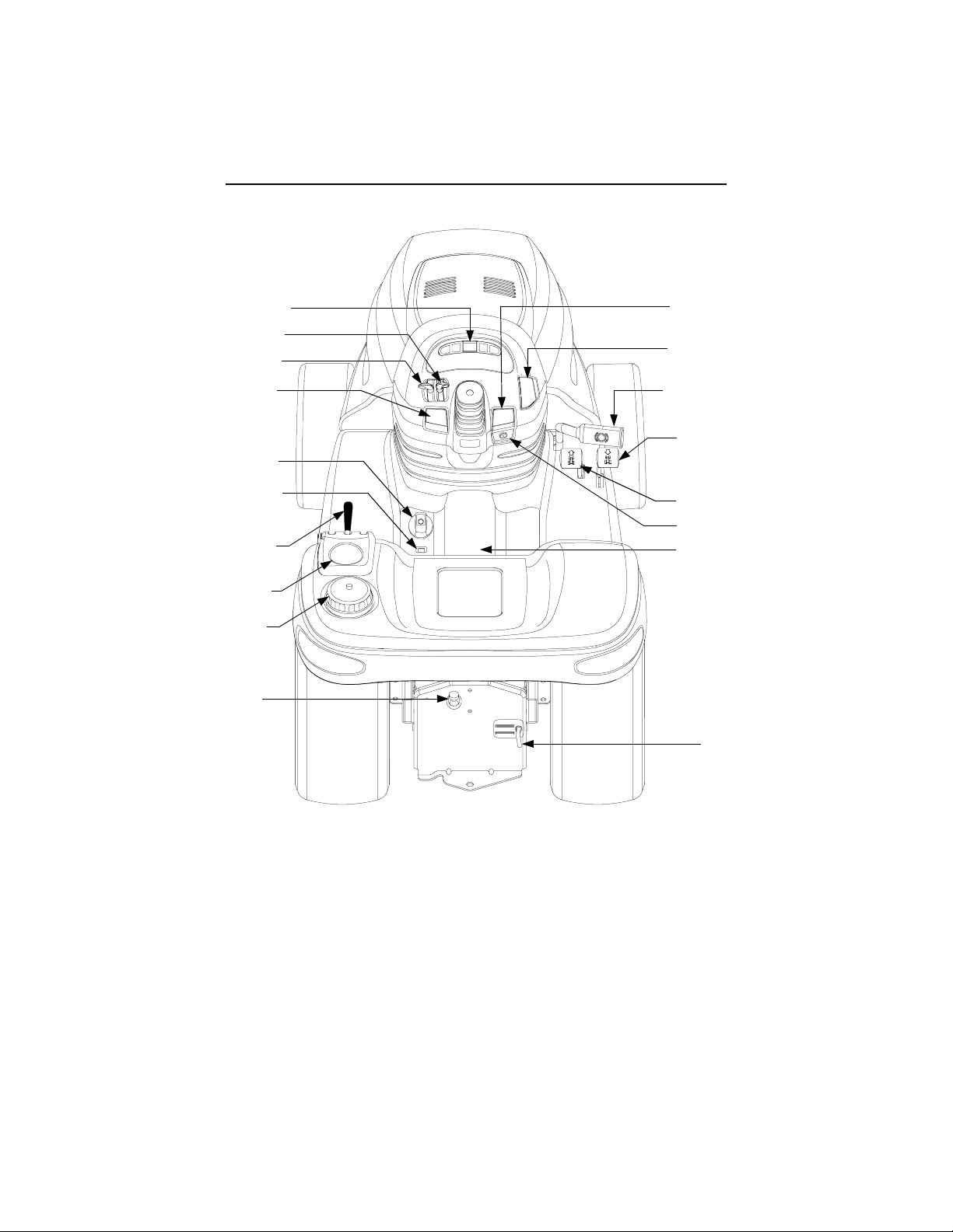
SECTION 6: CONTROLS
R
N
O
M
Q
F
L
K
J
I
A
B
C
D
E
G
P
(Not Shown)
H
Figure 3
A
Parking Brake Lever
B
PTO Switch
C
Brake Pedal
D
Reverse Pedal
E
Forward Pedal
F
Center Height Position Indicator
G
Ignition/Light Switch
H
Transmission Release Rod
I
Transmission Oil Fill /Dipstick
* Steering Wheel and Seat Removed For Clarity
J
Fuel Fill Cap
K
Cup Holder
L
Hydraulic Lift Lever
M
Cruise Control Lever
N
Choke Lever
O
Throttle Lever
P
Seat Adjust ment Lever (Not Shown)
Q
Deck Height Adjustment Knob
Indicator Light PodR
12
Page 13

NOTE: References to LEFT and
RIGHT indicate that side of the tractor
when facing forward while seated in
the drivers seat. Reference to FRONT
indicates the grille end of the tractor;
to REAR, the drawbar end.
Steering Wheel
The steering wheel is centered on the
dash panel. It is used to change the
direction (left or right) of the tractor
while driving.
NOTE: This tractor is equipped with
hydraulic power steering. With this
feature, the center of the steering
wheel may not stay center aligned.
Parking Brake Lever
Figure 4
The parking brake lever is located to
the right of the steering wheel on the
dash panel. With the brake pedal
depressed fully, push the parking
brake lever and release the brake
pedal to lock the parking brake.
PTO Switch
The PTO switch is loc ated o n the ri ght
side the dash panel. Pull upward on
the right edge of the switch handle to
engage the PTO clutch. Push the
switch downward to disengage the
PTO clutch.
Brake Pedal
disengage the cruise control. The
brake pedal must be fully depressed to
activate the safety interlock switch
when starting the tractor.
Reverse Pedal
Figure 6
NOTE: Check behind the tractor to
be sure the area is clear of people,
pets or obstacles and use a slower
speed to maintain control of the tractor
when traveling in reverse.
The reverse control pedal is located
on the right running board below the
brake pedal. Press the pedal down to
move in reverse.
Forward Pe dal
Figure 7
The forward control pedal is located
on the right running board below the
brake pedal. Slowly press down on the
pedal to start moving forward. The
forward ground speed of the tractor is
directly affected by the distance the
pedal is depressed.
Figure 5
The brake pedal is located at the front
of the right running board above the
forward and reverse pedals. Press
down to stop the tractor and
Center Height Position Indicator
The center height position indicator is
located in t he left running bo ard. This
indicator shows the operator the
relative height position setting of the
hydraulic center lift system. The lower
number indicates a lower setting.
13
Page 14

Ignition / Light Switch
To prevent accidental starting and/or
battery discharge, remove the key
from the ignition switch when the
tractor is not in use. The combination
lights and ignition switch has four
positions. See Figure 8 for a
description of each position.
Cup Holder
The cup holder is located on the
fender to the left of the seat.
Hydraulic Lift Lever
The hydraulic lift lever is located on
the fender to the left of the seat. This
lever is used to operate the tractor’s
center lift system.
Off
On/Lights
On
Start
Figure 8
T ransmission Release Rod
The transmission release rod is
located at the back of the tractor in the
draw bar. This rod, when engaged,
allows the tractor to be pushed short
distances by hand.
To disengage the transmission, pull
back on the rod until its locking flange
is visible outside the drawbar, then
lower the rod into the slot and release.
To reengage the transmission, pull
back on the rod, lift out of the slot and
release.
Transmission Oil Fill/Dipstick
The transmission oil fill/dipstick is
located at the back of the tractor in the
rear draw bar. The handle of the
transmission oil dipstick serves as
the fill tube plug and should fit snugly
in the fill tube.
Fuel Fill Cap
The fuel fill cap is located on the
fender to the left of the seat.
Cruise Control Lever
Figure 9
The cruise control lever is located to
the left of the steering wheel. Push the
cruise control lever downward while
traveling at the desired forward speed
to engage the cruise control.
Choke Lever
The choke lever is located to the left of
the steering wheel in the throttle/choke
lever pod. Push the lever forward to
close the engine choke plate.
Throttle Lever
This symbol shows the fast
position.
This symbol shows the slow
position
The throttle lever is located to the left
of the steering wheel in the throttle/
choke lever pod. This lever controls
the speed of the engine. Push the
lever forward to increase the engine
speed. When set in a given position,
the throttle will maintain a uniform
engine speed.
IMPORTANT: When using power
take-off operated equipment, best
performance is achieved with the
throttle lever in the “FAST” position.
14
Page 15

Seat Adjustment Lever
The seat adjustment lever is located
below the seat. This lever is used to
adjust the seat forward or back. Refer
to Figure 12 on page 19.
Deck Height Adjustment Knob
The deck height adjustment knob is
located on the left running board. Use
Indicator Light Pod
this knob to set (and hold) your
desired deckstop position for the
mower deck, regardless of whether
the deck caster/guage wheels contact
the ground.
• Turn the knob clockwise to raise the
deckstop position .
• Turn the knob counterclockwise to
lower the deckstop position.
A
A
Oil Pressure Indicator
B
Low Fuel Indicator
C
Hour Meter
B
Figure 10
Hour Meter
The hour meter is part of the indicator
light pod in the dash panel. The hour
meter operates whenever the ignition
switch is in the “ON” or “ON/LIGHTS”
position. Record the actual hours of tractor operation to ensure all maintenance
procedures are completed according to
the schedule in this manual.
Oil Pressure Indicator
WARNING: Operating the
tractor with low oil level or
pressure could result in
severe engine damage.
D
C
D
Not Used
E
Not Used
The oil pressure indicator is part of the
indicator light pod on the dash panel.
This indicator will illuminate when the
engine oil pressure is low. If this
indicator illuminates, stop the tractor
immediately and check the engine oil
level. If the oil level is within the
operating range, and the light remains
on, contact your Cub Cadet dealer.
E
Low Fuel Indicator
The Low Fuel indicator is part of the
indicator light pod on the dash panel.
This indicator will illuminate when the
tractor is low on fuel. If the gas tank is
full and the light stays on, contact your
Cub Cadet dealer.
15
Page 16

SECTION 7: OPERATION
Safety Interlock Switches
This tractor is equipped with a safety
interlock system for the protection of
the operator. If the interlock system
should ever malfunction, do not
operate the tractor. Contact your
authorized Cub Cadet Dealer. The
safety interlock system prevents the
engine from cranking or starting
unless the brake pedal is fully
depressed, and the PTO is “OFF”.
• The safety interlock system will
automatically shut off the engine if
the operator leaves the seat before
engaging the brake lock.
• The safety interlock system will automatically shut off the engine if the
operator leaves the seat with the PTO
“ON”, regardless of whether the brake
lock is engaged. The PTO switch
must be “OFF” to restart the engine.
• The safety interlock system will
automati cally sh ut off the P TO if the
reverse control pedal is depressed
with the PTO “ON”.
Fueling The Tractor
:Some fuels, called oxygen-
NOTE
ated or reformulated gasolines, are
gasoline blended with alcohols or
ethers. Gasolines blended with either
ethyl alcohol (Max. 10%) or methyl tertiary butyl ether (MTBE, Max. 15%)
are approved as fuels for this engine.
If any undesirable operating symptoms occur, use gasoline with a lower
percentage of these blends. Do not
use gasoline which contains Methanol
or other alcohol blends. For best
results use only clean, fresh,
unleaded gasoline with an octane rating of 87 o r higher. Purchase f uel in a
quantity that can be used within 30
days to assure fuel freshness. Do not
use gasoline left over from the pevious season to minimize gum deposits
in the fuel system. Leaded gasoline is
NOT RECOMMENDED. Leaded gasoline may be used in areas where
unleaded is not available and exhaust
emissions are not regulated.
Do not fill the fuel tank when the
engine is running or while the engine
is hot. Tighten the fuel cap securely.
Unscrew the fuel cap and fill the fuel
tank from an approved gasoline
container.
Starting The Engine
• Operator must be sitting in the
tractor seat.
• Push choke lever to the full choke
position. Less choking may be
necessary due to variations in
temperature, grade of fuel, etc. Little
or no choking will be needed when
the engine is warm.
• Place the throttle midway between
the “SLOW” and “FAST” position.
• Make sure the PTO sw itch is in the
“OFF” position.
• Fully depress the brake pedal.
• Turn the ignition key clockwise to
the “START” position and release it
as soon as the engine starts;
however, do not crank the engine
continuously for more than 10
seconds at a time. If the engine
does not start within this time, turn
the key to “OFF” and wait a minute
to allow the engine’s starter motor to
cool. Try again after waiting.
• After the engine starts, slowly
release the brake pedal. As the
engine warms up, gradually pull the
choke lever all the way back. Do not
use the choke to enrich the fuel
mixture, except when necessary to
start the engine.
Stopping The Engine
NOTE: Remove the key from the
ignition switch to prevent accidental
starting or battery discharge if the
equipment is left unattended.
16
Page 17

• Place the PTO switch in the “OFF”
position. Place the throttle control
lever between the “MID” and “FAST”
positions. Then turn the ignition key
to the “OFF” position.
• Remove the key from the ignition
switch.
Driving The Tractor
WARNING: Avoid sudden
starts, excessive speed and
sudden stops.
WARNING: Do not leave
the seat of the tractor
without disengaging the
PTO, depressing the brake
pedal and engaging the
parking brake. If leaving the
tractor unattended, also
turn the ignition key off and
remove the key.
• Depress the brake pedal to release
the parking brake and let the pedal
up. Move the throttle lever to the
position where the engine operates
best for the load to be handled
(normally full throttle).
NOTE: Do not use the forward or
reverse control pedals to change the
direction of travel when the tractor is in
motion. Use the brake pedal to bring
the tractor to a stop before depressing
either the forward or reverse control
pedal.
• To move forward, slowly depress
the forward control pedal until the
desired speed is achieved.
• To move in reverse, check that the
area behind is clear then slowly
depress the reverse control pedal.
Setting The Cruise Control
NOTE: The cruise control feature
can only be operated in the forward
direction.
• Slowly depress the forward control
pedal until the desired speed is
achieved.
• Lightly push th e cruise control lever
downward.
• While continuing to hold the cruise
lever down, lift your foot from the
forward control pedal (you should
feel the cruise latch engage).
• If properly engaged, the cruise lever
and forward control pedal should
lock in the down position, and the
tractor will maintain the same
forward speed.
• Disengage the cruise control using
one of the following methods:
- Depress the brake pedal to
disengage the cruise control
and stop the tractor.
- Lightly depress the forward
control pedal.
- Lift the cruise control lever
upward.
NOTE: Alt hough not recommende d,
depressing the reverse pedal will also
disengage the cruise control.
To change to the reverse direction
when operating with cruise control,
depress the brake pedal to disengage
the cruise control and stop the tractor;
then depress the reverse control pedal.
Driving On Slopes
Refer to the SLOPE GAUGE on page
53 to help determine slopes where you
may not operate safely.
WARNING: Do not mow
on inclines with a slope in
excess of 15 degrees (a rise
of approximately 2-1/2 feet
every 10 feet). The tractor
could overturn and cause
serious injury.
Operate the tractor up and down
slopes, never across slopes. Do not
drive so that the tractor may tip over
sideways.
17
Page 18

Before operating the tractor on any
slope, walk the slope to look for
possible hazards such as rocks.
mounds, ruts, stumps or other surface
irregularities which could cause the
tractor to be upset.
Back the tractor with attachment up
the steepest portion of each slope you
intend to work. If the tractor cannot
negotiate the slope in reverse, the
slope is too steep to be worked.
Avoid turn s when drivin g on a sl ope. I f
a turn must be made, turn down the
slope. Turning up a slope greatly
increases the chance of a roll over.
Avoid stopping when driving up a
slope. If it is necessary to stop while
driving up a slope, start up smoothly
and carefully to reduce the possibility
of flipping the tractor over backward.
Stopping The Tractor
Fully depress the brake pedal to bring
the tractor to a complete stop, engage
the parking brake, disengage the
PTO, turn the ignition switch to “OFF’”
and remove the key from the switch
before dismounting.
Using the Hydraulic Lift System
To raise an attachment using the
hydraulic lift system, the engine must
be running. Generally, an attachment
can be lowered with the engine
running or off. Push the hydraulic lift
lever forward to lower an attachment
or pull the hydraulic lift lever back to
raise an attachment.
Engaging The PTO
• Move the throttle control lever to
approximately the mid throttle
position.
• Pull the PTO switch to the “RUN”
position.
• Advance the throttle lever to the
operating speed (full engine speed).
• The operator must remain in the
tractor seat at all times. If the
operator should leave the seat
without turning off the PTO switch,
the tractor’s engine will shut off.
IMPORTANT: The PTO clutch
cannot be operated when the tractor is
driving in the reverse direction. The
PTO switch must in the “OFF” position
when the reverse control pedal is
depressed, or the PTO clutch will
automatically disengage. To reengage the PTO clutch, release the
reverse control pedal, move the PTO
switch to the “OFF” position, then
again pull the switch to the “RUN”
position.
Using The Drawbar
Drawbar equipment must be hitched to
the tractor only at the hitch hole. See
Figure 11.
Opening Tool Box
A convenient tool box and manual
pouch is located under the seat. To
access this area, pivot the seat
forward.
18
Hitch Hole
Drawbar
Figure 11
Page 19

SECTION 8: ADJUSTMENTS
Seat Adjustment
WARNING: Do not adjust
the seat when the tractor is
moving. Adjusting the seat
while the tractor is moving
could cause the operator to
lose control of the tractor.
To allow for the comfort of the
operator, an easy to operate adjustable
seat is a feature of this tractor. To
adjust the seat forward or back, slide
the seat adjustment lever to the left
and reposition the seat to the desired
location. Once you have found a
comfortable position, release the seat
adjustment lever. See Figure 12.
B
Front
A
Figure 13
To adjust toe-in loosen left and right
ball joint jam nuts. See Figure 14.
Turn the tie rod in or out of ball joints
as required. Tighten the jam nuts
against the ball joints.
Check for proper adjustment and
readjust as necessary.
Steering Axle
Hex Lock Nut
Seat Adjustment Lever
Figure 12
Front Wheel Alignment
Note: The left-hand ball joint is left-
hand threaded. The right-hand ball
joint is right-hand threaded.
The front wheels should toe-in approximately 1/8 inch. Measure distances A
and B. A should be approximately 1/8
inch less than B. See Figure 13.
Hex Jam Nut
Tie Rod
Ball Joint
Figure 14
Brake Inspection and Adjus tment
During normal operation, the tractor
brake is subject to minimal wear. However, the brake should be periodically
tested, and adjusted if necessary.
Checking the Brake.
Place the tractor on a firm and level
surface. Stop the engine and remove
the ignition key.
Pull and lock the transmission release
rod in the “Transmission Released”
position. Perform the following checks:
NOTE: The tractor may be difficult to
push because of the hydro transmission’s braking action.
• Engage the parking brake. If the
tractor can be pushed forward or
rearward, the braking force must be
increased.
19
Page 20

• Release the Parking Brake Lever. If
the tractor cannot be pushed
forward or rearward, the braking
force must be decreased.
Adjusting the Brake.
Remove the rear drawbar from the
frame by removing the four hex tapp
screws. NOTE: The oil fill tube/dipstick
will be pulled from the transmission
housing. Plug or cover the hole in the
transmission to prevent dirt or debris
from entering.
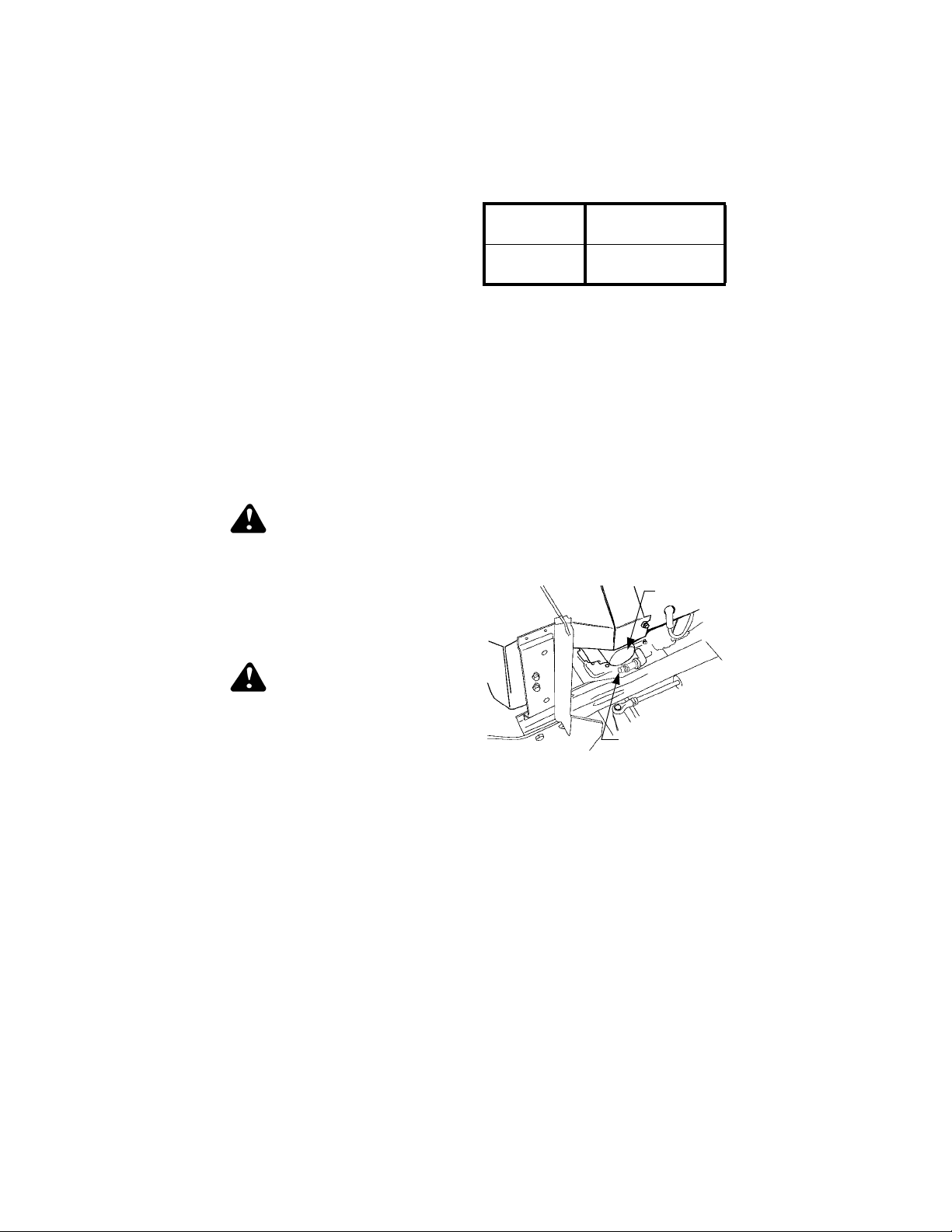
From beneath the right/rear side of the
tractor frame, secure the hex shaped
flange of the brake rod (located just
behind the brake link) to prevent the
rod from turning (See Figure 15).
From just above the right axle carrier,
inside the right frame rail, slowly turn
the hex nylon lock nut at the end of
the brake rod as follows to adjust the
brake (Refer to Figure 15):
• Turn the nylon lock nut clockwise to
increase the braking force.
• Turn the nylon lock nut counterclockwise to decrease the braking
force.
• Recheck the brake adjustment to
ensure proper operation, and
readjust as necessary. If brake
adjustment does not correct the
problem, see your authorized Cub
Cadet dealer.
While guiding the transmission release
rod through keyhole and the oil fill
tube/dipstick into the transmission,
position the rear drawbar on the
frame. Secure with the four hex tapp
screws.
Brake Link
Brake Assembly
(On Transmission)
Brake Rod
Hex Nylon
Lock Nut
VIEWED FROM ABOVE - FENDER
AND RUNNING BOARD REMOVED
Figure 15
Brake Shaft
Assembly
Hex Shaped
Flange
Turning Radius Adjustment
This tractor is equipped with power
assisted steering which is set at the
factory. The turning radius should be
equal for both left and right hand turns.
If adjustment is neces sary plea se contact your authorized Cub Cadet dealer.
20
Page 21

SECTION 9: MAINTENANCE
Maintenance Chart
Operation to
be performed
10 Hours
Each Use
Grease front wheel bearings •
Grease L/R steering knuckles •
Grease front pivot axle •
Check engine oil level •
Change engine oil and filter ‡ •••
Check spark plug condition •••
Check transmission oil level •
Change transmission oil filter •••••
Change transmission oil ••
Check air cleaner & housing •
Clean & re-oil foam air
pre-cleaner
Change air cleaner
paper cartride
Grease deck spindles •
Grease spindle belt idler arm •
Grease deck caster spindles •
Grease deck caster wheels
and gauge wheels
Grease deck drive shaft •
††
50 Hours
100 Hours
150 Hours
200 Hours
250 Hours
†††
•
300 Hours
‡ Change oil and filter after first 5 hours
† More often under dusty conditions
†† Clean every 25 hours or more often under dusty or dirty conditions
NOTE: We do not recommend the use of a pressure washer or garden hose to
clean your unit. They may cause damage to electrical components; spindles;
pulleys; bearings; or the engine. The use of water will result in shortened life
and reduce serviceability.
21
Page 22
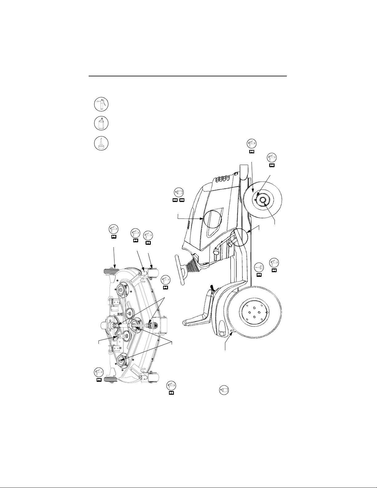
LUBRICATION ILLUSTRATION
Cub Cadet 251H EP Grease
or equivalent No. 2 lithium grease
Engine Oil: See Figure 24 on page 33
Transmission Oil- Cub Cadet Drive
System Fluid Plus - ONLY
Oil Can (High quality lubricating oil)
Engine
5
100
Deck Gauge Wheels
Deck Caster Spindles
Deck Caster Wheels
Front Pivot Axle
L/R Steering Knuckles
10
10
Idler Arm
10
50
50
50
Deck Drive Shaft
50
Deck Spindles
10
22
Front Wheels
Foot Control
Pivot Points
10
10
Transmission
See Maintenance
Chart
Page 23

Accessing Engine Compartment
The engine compartment can be
accessed by lifting the hood upward
from the re cessed notc hes of the s ide
panels and tipping the hood forward. If
greater access is required, the tractor
is equipped with quick release side
panels.
Remove the quick release side panels
as follows (see Figure 16):
• Open the hood by lifting upward at
the side panel notches on each side
of the tractor.
• Flip the tab of the two quick release
fasteners up and turn to align with the
slots in side pan els.
• Swing the rear of the side panel out
and away from the tractor.
Lift Hood Here
• Slide the side panel rearward to
disengage the two front tabs of the
side panel from the slots of the
grille/side panel mounting strip.
To reinstall the side panels:
• Insert the side panel front tabs into
the slots of the grille/side panel
mounting strip.
• Swing the rear of the side panel
inward and a lign so that t he tabs of
the quick release fasteners go
through the side panel slots.
• Pull the quick release fastener tabs
slightly outward and rotate 1/4 turn
(perpendicular to slot) to lock the
side panels in place.
• Flip the fastener tabs down and
close the hood.
Quick Fasteners
Turn
Flip up
Figure 16
23
Page 24

General Battery Information
WARNING
• Battery posts, terminals and related
accessories contain lead and lead
compounds. Wash hands after
handling.
• Battery acid must be handled with
great care, as contact with it can
burn and blister the skin. It is
advisable to wear protective clothing
(goggles, rubber gloves and apron)
when working with acid.
• Should battery acid accidentally
splatter into the eyes or onto the
skin, rinse the affected area
immediately with clean cold water. If
there is any further discomfort, seek
prompt medical attention.
• If acid spills on clothing, first dilute it
with clean water, then neutralize
with a solution of ammonia/water or
baking soda/water.
• Since battery acid is corrosive, do
not pour it into any sink or drain.
Before discarding an empty electrolyte container, rinse it thoroughly
with a neutralizing solution.
• NEVER connect (or disconnect)
battery charger clips to the battery
while the charger is turned on, as it
can cause sparks.
• Keep all sources of ignition
(cigarettes, matches, lighters) away
from the battery. The hydrogen gas
generated during charging can be
combustible.
• As a further precaution, only charge
the battery in a well ventilated area.
• Always shield eyes and protect skin
and clothing when working near
batteries.
Battery Removal
WARNING: Batteries contain sulfuric acid and may
emit explosive gases. Use
extreme caution when handling batteries. Keep
batteries out of the reach of
children.
WARNING: Battery posts,
terminals and related acce ssories contain lead and lead
compounds. Wash hands
after handling.
The battery is located under the dash
panel in the frame pedestal. Remove
the battery as follows:
• Open the tractor hood by lifting it at
the notches in the side panels.
• Remove the upper baffle of the
bulkhead from the front of the dash
panel by lifting upward on the
locking tab on each side of the
baffle.
• Pull the upper end of the rubber
battery strap rearward to unhook it
from the tab on the pedestal.
• Loosen the negative battery cable
clamp and disconnect the negative
lead from the battery first; then
disconnect the positive lead from
the battery.
• Carefully lift the battery up and out
of the tractor.
Install the battery by repeating the
above steps in the reverse order.
ALWAYS CONNECT THE POSITIVE
LEAD TO THE BATTERY BEFORE
CONNECTING THE NEGATIVE
LEAD.
24
Page 25

Battery Maintenance
The battery is filled with battery acid
and then sealed at the factory.
However, even a “maintenance free”
battery requires some maintenance to
ensure its proper life cycle.
• Spray the terminals and exposed
wire with a battery terminal sealer,
or coat the te rmi nals w ith a thin coat
of grease or petroleum jelly, to
protect against corrosion.
• The battery should be kept clean.
Any deposits of acid should be
neutralized with baking soda and
water. Be careful not to get this
solution in the cells.
• Avoid tipping the battery. Even a
“sealed” battery will leak electrolyte
when tipped.
Battery Storage
• When storing the tractor for extended
periods, disconnect the battery
cables. Removing the battery from
the unit is recommended.
• All batteries discharge during
storage. Keep the exterior of the
battery clean, especially the top. A
dirty battery will discharge itself
more rapidly.
• The battery must be stored with a
full charge. A discharged battery will
freeze at a higher temperature.
Specific Gravity Freezing Point
1.265 –71°F
1.250 –62°F
1.200 –16°F
1.150 5°F
1.100 16°F
• Recharge the battery before
returning to service; or every two
months, whichever comes first.
Headlight Bulb Replacement
Replace headlight bulbs as follows:
(See Figure 17)
Terminal
Socket Tab
Socket
Reflector Housing
Reflector Notch
Figure 17
1. Unplug the wire harness leads
from the headlight socket
terminals. Note which wire
connects to each terminal before
disconnecting.
2. Rotate the socket assembly as
follows to remove from the
reflector housing:
• Left headlight — appoximately 1/4
turn counterclockwise.
• Right headlight — approximately
1/4 turn clockwise.
3. Push the bulb inward and turn
counterclockwise to remove from
the socket.
4. Align a locking post of the bulb
base with the notch in the socket,
then push the bulb inward and
turn clockwise to lock
5. With the terminals pointing
upward, align the tab of the
socket with the notch of the
reflector. Push the socket inward
and turn as follows to lock:
• Left headlight — appoximately 1/4
turn clockwise.
• Right headlight — approximately
1/4 turn counterclockwise.
6. Connect th e wi r e har n e ss l ead s t o
the appropriate socket terminals.
25
Page 26

Tire Inflation
Keep the tires inflated to the
recommended pressure. Improper
inflation will affect tire life and operator
comfort, and also will affect the
leveling of the mower deck and quality
of cut.
See the tire side wall for proper
inflation range.
Ensure that the valve caps are
securely tightened in place to prevent
air loss and to protect the valve core.
Do not overload the tractor tires by
mounting equipment on the tractor
which exc eeds the load ca pacity of the
size of the tires on the tractor.
Dipstick Reading
F
Operating
Range
A
Transmission
Oil Fill Tube/
Dipstick
Figure 18
Checking Transmission Oil Level
NOTE: Check the oil level only while
the engine is stopped and the tractor
is level.
Check the oil level of the transmission
case befor e each use to s ee that it is
filled to the correct level. Before
checking the transmission oil level,
clean the area around the
Transmission Oil Fill/Dipstick to
prevent debris from entering the
transmission case. Always keep the oil
level between the “FULL” and the
“ADD” marks on the dipstick. When
checking the oil level, the dipstick
must be withdrawn and wiped clean,
then reinserted all the way before
being withdrawn again for a true
reading.
Adding Transmission Oil
WARNING: The fluid for your
transmission has been specially formulated to ensure
the safe and proper operation of your tractor. Add Cub
Cadet Drive System Fluid
Plus ONLY. Do not use any
other fluid.
WARNING: Never overfill the
transmission case. Damage
may result if the oil level in
the transmission case is
below the “ADD” mark or
over the “FULL” mark of the
dipstick.
For best results, fill to the “FULL” mark
on the dipstick as opposed to adding a
given quantity of oil. Always check the
level on the dipstick before adding
more oil. See Figure 18.
Refer to the Lubrication Illustration for
information regarding the proper type
of oil to add to the transmission case.
See the Specifications Chart for the
quantity required.
• Place the tractor on a level surface
and engage the parking brake. Stop
the tractor engine and remove the
ignition key.
• Clean the area around the
Transmission Oil Fill/Dipstick to
prevent debris from entering the
transmission case.
• Remove the dipstick from the oil fill
tube and SLOWLY pour oil into the
oil fill tube. Fill the transmission
case until the oil level reaches the
“FULL” mark on the dipstick.
26
Page 27

• Reinstall the dipstick securely into
the oil fill tube.
WARNING: The oil fill plug /
dipstick must be installed
securely into the fill tube at
all times when the engine is
operating.
Changing Transmission Oil
WARNING: The fluid for your
transmission has been specially formulated to ensure
the safe and proper operation of your tractor. When
changing the transmission
fluid replace it with Cub
Cadet Drive System Fluid
Plus ONLY. Failure to use
Cub Cadet Drive System
Fluid Plus may result in a
failure of the drive system
which could result in property damage or personal
injury. Do not use any other
fluid
See to the Maintenance Chart for the
frequency of service and the Specifications Chart for the quantity required.
• Place the tr actor on a level surface
and engage the parking brake. Stop
the tractor’s engine and remove the
ignition key.
• Remove any center mounted
attachments.
• Clean the area around the transmission drain plug to prevent debris
from entering the transmission case.
Remove the drain plug and allow
the transmission oil to drain into a
clean container having a capacity of
more than 5 quarts. Reinstall the
drain plug. See Figure 19.
Transmission
Oil Filter
Transmission
Drain Plug
Figure 19
NOTE: Do not reus e the transmis sion
oil. Contaminated transmission oil can
damage the hydro transmission.
Please dispose of used oil
at appropriate recycling
centers.
• Clean around the base of the
transmission oil filter and remove
the filter by turning it
counterclockwise.
• Apply a light coating of clean
transmission oil to the gasket of the
new filter. Install the filter by turning
it clockwise, by hand, until the
gasket contacts the filter base on
the transmission housing; then
tighten the filter an additional 1/2
turn.
• Clean the area around the
Transmission Oil Fill/Dipstick to
prevent debris from entering the
transmission case.
• Remove the dipstick and SLOWLY
pour oil into the oil fill tube. Fill the
transmissio n case until the oil level
reaches the “FULL” mark on the
dipstick.
27
Page 28

• Reinstall the dipstick securely into
the oil fill tube.
• Start the engine and allow it to run
for a few minutes. Shut the engine
off, then check for leaks and
recheck the oil level in the
transmission case.
Important Information: The service
life and reliability of any machine
depends upon the care it is given.
Proper lubrication is a very important
part of that care. The maintenance
schedule reflects the minimal
requirements to maintain the
equipment. More frequent inspections
and maintenance is preferable.
Using the lubrication illustration as a
guide, make certain that all lubrication
fittings are installed and functioning.
Be sure all fittings are free from dirt
and paint so the lubricant is certain to
enter the bearing.
Using a pressure lubricating gun,
always force the lubricant through the
full length of each bearing until it
emerges at the end, carrying with it
the worn lubricant and any dirt that
may have entered the bearing.
Miscellaneous working parts not
provided with lubrication fittings should
be oiled regularly with a good grade of
lubricating oil.
Always lubricate the tractor thoroughly
before taking it to a remote location for
a prolonged period of time.
Lubricant is cheap. Use plenty of it.
Worn parts can be expensive to
replace.
Keep your supply of lubricating oil and
grease stored in clean containers, and
covered to protect from dust and dirt.
Keep the lubricating gun nozzle clean
and wipe dirt from the grease fittings
before lubricating.
Electrical Box
The electrical box contains the relay
and fuses. See Figure 20 for the
electrical box layout. The electrical box
is located under the upper bulkhead in
front of the dash panel. To access the
electrical box:
• Raise the hood of the tractor
• Locate the locking tabs on the left
and right side of the upper
bulkhead.
• Pull up on the tabs and lift the upper
bulkhead from the tractor.
• Lift the locking tab and remove the
cover from the electrical box.
Open
25 Amp
Fuses
Relay
Open
Figure 20
Fuse
Fuses are installed to protect the
tractor’s electrical system from
damage caused by excessive
amperage.
Always use the same capacity fuse for
replacement. Refer to the
Specifications Chart. If the electrical
system does not function, check the
fuses.
28
Page 29

To replace a fuse, note the position of
the fuse and pull the old fuse from the
electical box.
Compare the suspect fuse with Figure
21 to determine if is good or bad.
GOOD BAD
Figure 21
Install the new fuse in the position
from which the old fuse was removed.
Off-Season Storage
If the machine is to be inoperative for
a period longer than 30 days, the following procedures are recommended:
WARNING: Never store the
tractor with fuel in the tank
indoors or in poorly ventilated enclosures, where fuel
fumes may reach an open
flame, sp ark or pilo t light as
on a furnace, water heater,
clothes dryer, etc.
WARNING: Fuel left in the
fuel tank deteriorates and
will cause serious starting
problems.
To prevent gum deposits from forming
inside the engine’s carburetor and
causing possible malfunction of the
engine, the fuel system must be either
completely emptied, or the gasoline
must be treated with a stabilizer to
prevent deterioration.
1. If using a fuel stabilizer:
• Read the product manufacturer’s
instructions and recommendations.
• Add to clean, fresh gasoline the
correct amount of stabizer for the
capacity of the fuel system.
• Fill the fuel tank with treated fuel
and run the engine for 2-3 minutes to get stabilized fuel into the
carburetor.
2. If emptying the fuel system:
• Towards end of the season,
monitor fuel consumption with the
goal of running the fuel tank to
empty.
• If a large volume of fuel is leftover, remove the fuel cap and
siphon the the bulk of any leftover
fuel into an approved container.
• Run the engine until it starts to
falter, then use the choke to keep
the engine running until all fuel in
the carburetor has been exhausted.
3. Perform the following procedures
before storing the machine.
• Remove the spark plugs and pour
one (1) ounce of engine oil
through the spark plug holes into
the cylinders. Install the spark
plugs but do not connect the plug
wires. Crank the engine two or
three revolutions to distribute the
oil.
• Clean the engine and the entire
tractor thoroughly.
• Lubricate all lubrication points.
• Prepare the battery for storage.
• Protect the tires and seat from
sunlight. Regularly check the tires
for proper inflation.
NOTE: We do not recommend the use
of a pressu re washer or garden hose
to clean your unit. They may cause
damage to electrical components;
spindles; pulleys; bearings; or the
engine. The use of wate r will resul t in
shortened life and reduce
serviceability.
29
Page 30

SECTION 10: ENGINE INFORMATION
KOHLER CO.
FEDERAL AND CALIFORNIA EMISSION CONTROL SYSTEMS
LIMITED WARRANTY
UTILITY AND LAWN AND GARDEN ENGINES
The U.S. Environmental Protection Agency (EPA),
the California Air Resources Board (CARB), and
Kohler Co. are pleased to explain the Federal and
California Emission Control Systems Warranty on
your utility/lawn/garden equipment engine (herein
engine). For California, engines produced in 1995
and later must be designed, built and equipped to
meet the state’s stringent anti-smog standards. In
other states, new 1997 and later model year
engines must be designed, built and equipped, at
the time of sale, to meet the U.S. EPA regulations
for small non-road engines. The engine must be
free from defects in materials and workmanship
which cause it to fail to conform with U.S. EPA
standards for the first two years of engine use from
the date of sale to the ultimate purchaser. Kohler
Co. must warrant the emission control system on
the engine for the period of time listed above,
provided there has been no abuse, neglect or
improper maintenance.
The emission control system may include parts
such as the carburetor or fuel injection system, the
ignition system, and catalytic converter. Also
included are the hoses, belts and connectors and
other emission related assemblies.
Where a warrantable condition exists, Kohler Co.
will repair the engine at no cost, including
diagnosis (if the diagnostic work is performed at an
authorized dealer), parts and labor.
MANUFACTURER’S WARRANTY
COVERAG E
Engines produced in 1995 or later are warran ted
for two years in C alifornia. In other st ates, 1997
and later model y ear engines are warranted for
two years. If any emission related part on the
engine is defective, the part will be repaired or
replaced by Kohler Co. free of charge.
OWNER’S W ARRANTY
RESPONSIBILITIES
(a) The engine owner is r esponsible fo r the per-
formance of the r equired maintenance listed
in the owner’s manual. Kohler Co. recommends that you retain all receipts covering
maintenance on the engine. But Kohler Co.
cannot deny warr anty solely for the lack of
receipts or for your fai lure to assure that all
scheduled maintenance was performed.
• Oxygen sensor (if equipped)
• Exhaust manifold (if equipped)
• Fuel metering valve (if equipped)
• Crankcase breather (if equipped)
• Gaseous fuel regulator (if equipped)
• Carburetor or fuel injection system
• Air filter, fuel filter, and spark plugs (only to first
scheduled replacement point)
(b) Be aware, however, that Kohler Co. may deny
warranty coverage if the engine or a part has
failed due to abuse, neglect, improper maintenance or unapproved modifications.
(c) For warranty repairs, the engine must be pre-
sented to a Kohler Co. service center as soon
as a problem exists. Call 1-800-544-2444 for
the names of the nearest service centers.
The warranty repairs should be completed in
a reasonable amount of time, not to exceed
30 days.
If you have any questions regarding warranty
rights and responsibilities, you should contact
Kohler Co. Engine Service at 1-920-457-4441.
COVERAGE
Kohler Co. warrants to the ultimate purchaser and
each subsequent purchaser that the engine will be
designed, built and equipped, at the same time of
sale, to meet all applicable regulations. Kohler Co.
also warrants to the initial purchaser and each
subsequent purchaser, that the engine is free
from defects in material and workmanship which
cause the engine to fail to conform with applicable
regulations for a period of two years.
Engines produced in 1995 or later are warranted
for to years in California. For 1997 and later model
years, EPA requires manufacturers to warrant
engines for two years in all other states. These
warranty periods will be begin on the date the
engine is purchased by the initial purchaser. If any
emission related part on the engine is defective,
the part will be replaced by Kohler Co. at no cost
to the owner. Kohler Co. is liable for damages to
other engine components caused by the failure of
a warranted part still under warranty.
Kohler Co. shall reme dy warranty defects at any
authorized Kohler Co. engine dealer or warranty
station. Warranty re pair work done at an authorized dealer or warr anty station shall be free of
charge to the owner if su ch work determi nes that
a warranted part is defective.
Listed below are th e pa rts cove red by the Federal
and California Emission Control Systems
Warranty. Some parts listed below may require
scheduled maintenanc e and are warranted up to
the first scheduled replace men t po int for tha t par t.
The warranted parts are:
• Intake manifold (if equippe d)
• Catalytic muffler (if equipped)
• Spark advance module (if equipped)
• Ignition module(s) with high tension lead
• Electronic control unit (if equippe d)
• Fuel lines (if equipped)
30
Page 31

LIMITATIONS
This Emission Control System Warrant y shall not
cover any of the following:
(a) repair or replacement required because of
misuse or neglect, improper maintenance,
repairs improperly performed or replacement
not conforming to Kohler Co. specifications
that adversely affect performance and/or
durability and alterations or modifications not
recommended or approved in writing by
Kohler Co.,
(b) replacement of parts and other services and
adjustments necessary for required maintenance at and after the first scheduled
replacement point,
(c) conse quent ial dama ges such as loss of time ,
inconvenience, loss of use of the engine or
equipment , etc.,
(d) diagnosis and inspection fees that do not
result in eligible warranty service being performed, and
(e) any add-on or modifi ed part, or malfunction
of authorized parts due to the use of add-on
or modified parts.
MAINTENANCE AND REPAIRS
REQUIREMENTS
The owner is responsible for the proper use and
maintenance of the engine. Kohler Co. recommends that all receipts and records covering the performance of regular maintenance be retained in
case questions arise. If the engine is resold during
the warranty period, the maintenance records
should be transferred to each subsequent owner.
Kohler Co. res erves the right to deny w arran ty coverage if the engine has not been properly maintained;
however, Kohler Co. may not deny warranty repairs
solely because of the lack of repair maintenance or
failure to keep maintenance records .
Normal maintenance, replacement or repair of
emission control devices and systems may be performed by any repair establishment or individual;
however , war ra nt y re pa ir m us t be pe rformed by a
Kohler authorized service center. Any replacement part or service that is equivalent in
performance and durability may be used in non-warranty maintenance or repairs, and shall not reduce
the warranty obligations of the engine manufacturer.
Maintenance, repair or replacement of the emission control devices and
systems, which are being done at the customers expense, may be performed by
any non-road engine repair establishment or individual. Warranty repairs must
be performed by an authorized warranty outlet.
31
Page 32

Cleaning The Engine
This tractor has an air-cooled engine.
Air must be able to circulate freely
around the engine through the
flywheel screen, through the cooling
shrouds and over the fins of the
cylinder head and cylinder block. Keep
these areas free of accumulated dirt
and debris or the engine will overheat;
possibly causing extensive engine
damage. Regularly clean the inside of
the side panels, dash intake screen
and grille to ensure adequate cooling.
If debris has accumulated inside the
cooling shrouds, the blower housing
and cooling shrouds should be
removed and the cooling fins cleaned.
WARNING: This machine is
designed to cool properly with
the side panels in place.
Operating without the panels
could cause premature
accumulation of dirt and
debris on the engine, resulting
in inadequate cooling.
WARNING: Keep the muffler
area clean. Before run ning th e
engine, clean the muffl er area
to remove all combustible
debris. Inspect the muffler
area often when mowing
during the Fall season.
Checking Engine Oil Level
Before each use, the oil level of the
engine crankcase should be checked
to see that it is filled to the correct
level. Close monitoring of the oil level
during the first 10 hours of operation
of the engine is especially important
and the oil level should be checked
EVERY HOUR during the first five
hours of operation.
Before checking the oil level, clean the
area around the oil level dipstick to
prevent debris from entering the
crankcase. See Figure 23. Always
keep the oil level be tween the “ FULL”
and the “ADD” marks on the dipstick.
See Figure 22.
F
Full
Add
When checking the oil level, the
engine must be cold, the dipstick must
be withdrawn and wiped clean, then
inserted all the way into the tube
before being withdrawn for a true
reading.
Check the oil level only while the
engine is stopped and the tractor is
level.
Operating
Range
A
Figure 22
Adding Engine Oil
Dipstick
WARNING: Never overfill the
engine crankcase. The
engine may overheat and/or
damage may result if the
crankcase is below the
“ADD” mark or over the
“FULL” mark on the dipstick.
For best results, fill to the
“FULL” mark on the dipstick
as opposed to adding a given
quantity of oil. Always check
the level on the dipstick
before adding more oil.
Oil Fill Cap
Figure 23
32
Page 33
Refer to Figure 24 for information
regarding the proper type of oil to add
to the crankcase.
• Place the t ractor on a level surface
and engage the parking brake. Stop
the tractor engine and remove the
ignition key.
• Clean the area around the oil filler
cap to prevent debris from entering
the crankcase. See Figure 23.
• Remove the oil filler cap from the
left valve cover and SLOWLY pour
in oil. Fill the crankcase until the oil
level reaches the “FULL” mark on
the dipstick. See Figure 22.
• Reinstall the oil filler cap and turn to
the right to tighten securely in the
valve cover.
WARNING: The oil filler cap
must be tightened securely
into the valve cover at all
times when the engine is
operating. Severe engine
damage could result from
failure to do so.
Changing Engine Oil
WARNING: If the tractor has
recently been operated, the
engine and surrounding
areas may be hot. Use caution not to burn yourself
when working around the
engine.
The oil filter should be changed at
every oil change interval. The filters
can be obtained through your Cub
Cadet dealer. See the Quick
Reference Chart on page 60 for the
correct part number. Refer to the
MAINTENANCE CHART on page 21
and the SPECIFICATIONS TABLE on
page 52 for information regarding the
frequency of required oil changes and
the quantity of oil needed.
See the VISCOSITY CHART in Figure
24 for the proper type of oil.
Above +32° F SAE 10W30
SAE 10W40
Below +32° F SAE 5W20
SAE 5W30
Figure 24
The oil filter is located behind the left
side panel and is mounted on the
engine. See Accessing Engine
Compartment on page 23 for details
on removing the side panels.
Run the engine for a few minutes to
warm the oil in the crankcase. Warm
oil will flow more freely and carry away
more engine impurities. Use care to
avoid burns from hot oil. While the
engine oil is warm, proceed as follows:
NOTE: A length of flexible tubing is
supplied with the tractor and should be
used to drain the engine oil.
Oil Filter
Oil Drain Valve
Figure 25
• Place the tractor on a level surface
and engage the parking brake. Stop
the tractor engine and remove the
ignition key.
• Clean around the base of the oil
filter, the oil filler cap, and the
dipstick tube to prevent debris from
entering the crankcase. See Figure
23 and Figure 25.
• Unseat the plastic dust cap from the
engine oil drain valve. To prevent
loss of the cap, do not remove the
cap’s retaining ring from the drain
valve. Remove the dipstick.
33
Page 34

• Attach the flexible tubing to the
drain valve. Place an appropriate
container below the open end of the
tubing to collect the old oil.
• To open the drain valve, push it
slightly inward and turn it
counterclockwise until it stops, then
pull it outward.
• Remove the filter by turning it counterclockwise using an automotive
type filter wrench to loosen.
• Allow the old oil to completely drain
from the engine crankcase into the
container below. To close the drain
valve, push it inward, turn clockwise
until it stops and then release it.
• Remove the flexible tubing from the
drain valve. Clean the tubing and
store in a safe place for future use.
• Clean the drain valve and push the
plastic dust cap onto the valve.
• Turn the r ep l ac em en t fi lte r op e n e nd
up and pour new oil into the filter
through the threaded center hole.
Fill to the bottom of the threads,
then wait a minute or two to allow
the oil to be absorbed into the filter
material.
• Apply a light coating of clean oil on
the gasket of the new oil filter.
Thread the filter on by hand until the
gasket contacts the oil filter adapter,
then tighten the oil filter an
additional 1/2 turn.
• Refill the crankcase with the
appropriate quantity and type of oil.
• Check oil level and make sure that
oil filler cap, dipstick and drain valve
are in place and closed.
Check the gap after every 100 hours
of operation.
Replace a defective plug with a new
plug. Set the spark plug gap at .030
inch. Tighten the plug to 18-22 ft-lbs.
See your authorized dealer for the
correct replacement plug.
Changing Fuel Filter
WARNING: Do not replace
fuel filter when engine is hot.
The engine is equipped with an in-line
fuel filter. Visually inspect the filter
periodically for a build-up of residue
inside the filter body, and for a dirty
element which can be indicated by
discoloration. Replace the fuel filter
when dirty.
Changing Air Cleaner
Air Cleaner
Cover w/Knob
Element Cover
Wing Nut
Element Cover
Rubber Seal
Foam
Precleaner
Paper Element
Air Cleaner Base
Sparkplugs
WARNING: To avoid possible injury, be sure the engine is off and has cooled
before making any adjustments or repairs.
Remove all dirt from around the spark
plug before removing.
Use a spark plug wrench to remove
the spark plugs.
Figure 26
Check the air cleaner daily or before
starting the engine. Check for loose or
damaged components and check the
condition of the filter element. Remove
any buildup of dirt and debris in the air
cleaner housing.
See Figure 26 for assembly of the Air
cleaner elements.
34
Page 35

WARNING: Operating the
engine with loose or damaged air cle a ner co m pon en ts
will allow unfiltered air into
the carburetor, causing extensive wear and eventual
failure of the engine.
Servicing The Precleaner
Wash and re-oil the foam precleaner
more often under extremely dusty or
dirty conditions. See Figure 26.
• Loosen the aircleaner cover knob
and remove the cover.
• Remove the foam precleaner by
sliding it up off the paper element.
• Wash the precleaner in warm water
with detergent. Rinse the precleaner
thoroughly until all traces of the
detergent are eliminated. Squeeze
out (do not wring) excess water in a
dry cloth. Allow the precleaner to air
dry.
• Saturate the foam precleaner with
new engine oil. Squeeze out all
excess oil in a dry cloth.
• Reinstall the foam precleaner over
the paper element.
• Reinstall the air cleaner cover and
tighten the retaining knob to secure.
Servicing The Paper Element
Inspect and replace the paper element
as necessary. See Figure 26.
• Loosen the air cleaner cover knob
and remove the cover.
• Remove the foam precleaner by
sliding it up off the paper element.
• Clean the area around the element
to prevent debris from getting into
the engine when the element is
removed.
• Loosen and remove the element
cover wing nut.
• Remove the air filter element and
element cover by lifting straight up.
• Do not wash the paper element or
use pressurized air, as this will
damage the element. Replace a
dirty, bent or damaged element.
Handle new elements carefully; do
not use if the sealing surfaces are
bent or damaged.
• When servicing the air cleaner,
check the air cleaner base. Make
sure it is secured and not bent or
damaged. Ch eck the eleme nt cover
plate for damage or improper fit.
Also check the rubber seal for
damage or deterioration. Replace all
damaged air cleaner components.
• Reinstall the paper element, foam
precleaner, cover plate and element
cover wing nut.
• Reinstall the air cleaner cover and
tighten the retaining knob to secu re.
IMPORTANT: Properly maintained air
cleaner elements significantly
contribute to prolonging engine life.
35
Page 36

SECTION 11: MOWER DECK
Deck Leveling Adjustments
The 44" mo wer deck is eq uipped with
ground following front caster wheels
and is designed to be operated with
the caster wheels on the ground. However, if desired, the deck can be
suspended off the ground by utilizing
the deck height adjustment knob to set
the deck downstop position. In either
case, to ensure an even cut on all
types of terrain, the mower deck
should be properly leveled. The side to
side leveling procedure will result in
the left and right blades having corresponding cutting-edge-to ground
measurements within 1/16 inch of
each other. Also, the cutting blades
will have a downward tilt toward the
front of the tractor of approximately 1/8
inch. To level the mower deck, proceed as follows:
WARNING: Before making
adjustments, place the PTO
switch in the “OFF” position, engage the parking
brake lever, and turn the
ignition key to “OFF” position and remove the key.
Use care not to cut yourself on the sharp blades.
NOTE: Place the tractor w/ deck on a
hard, level surface and check for
proper tire inflation before checking
and making any leveling adjustments.
A. Side T o Side Leveling Adjustment
1. Position the tractor on a hard,
level surface.
2. Use the tractor hydraulic lift system to raise the deck to its
highest position. Stop engine.
3. To prevent contact with the surface below, adjust the front caster
and rear gauge wheels to their
highest setting (lowest deck setting). If necessary, refer to C.
Setting The Cutting Height.
4. Carefully rotate the outer cutting
blades so that they are posi-
tioned perpendicular to the tractor
frame (See Figure 27).
Outer Blades
Perpendicular to Frame
Figure 27
5. Referring to Figure 28, measure
and record the distance from the
hard, level surface to the outermost cutting edge of the right
blade. Repeat this step for the left
blade. If the two blade heights are
not within 1/16 inch, the deck
must leveled. Note whether the
left blade had the larger or
smaller distance between the cutting edge and level surface. If the
two blade heights are within 1/16
inch, proceed to B. Front To
Back Leveling Adjustment.
Blade
Measure
Finger
Guard
6. Side to side leveling is attained by
adjusting the hex lock nut on the
bottom of the LH lift rod, below
the LH lift link (See Figure 29).
7. Turn the hex lock nut upward
(tighten) on the threads of the lift
rod to raise the left side of the
mower deck. Turn the lock nut
down (loosen) on the threads to
lower the left side of the mower
deck.
Hard Level
Surface
Figure 28
This
Distance
36
Page 37
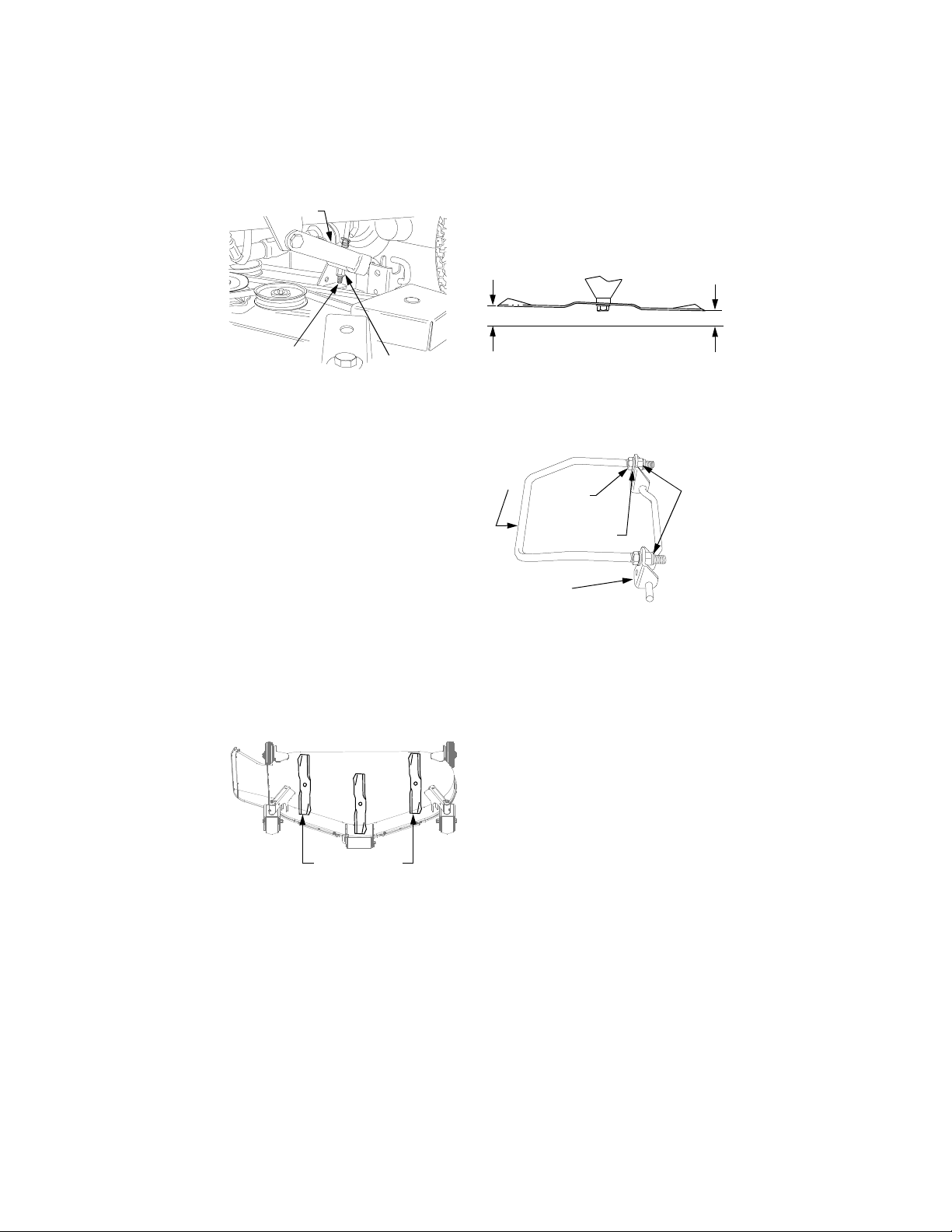
LH Lift Link
should be lower than its back
edge (measure B) by approximately 1/8 inch.
LH Lift Rod
Figure 29
Hex Lock Nut
8. Recheck the measurements described in step 5. If the blade measurements are not within 1/16
inch, repeat steps 5 and 7 until
the correct measurement is
obtained.
B. Front to Back Leveling
The front lift rod must be correctly
adjusted to ensure the deck maintains
the proper pitch when mowing uneven
terrain.
1. Using the tractor’s lif t system, raise
the deck to one of the higher cutting
positions. Make certain the front
caster and rear gauge wheels do
not touch the surface below.
2. Position the mower blades so the
ends of each blade point to the
front and the rear of the tractor
(See Figure 30).
Outer Blades
Positioned Front to Rear
Figure 30
3. Refer to Figure 31. Measure and
record the distance from the front
cutting edge to the ground (measure A), and from the rear cutting
edge to the ground (measure B),
for both outer blades. The front
edge of each blade (measure A)
Rear
Cutting
Edge
B
Figure 31
Front
Cutting
Edge
A
4. Adjust the front lift rod as follows
to attain the proper pitch of the
mower deck (See Figure 32).
Front
Lift
Rod
Hex
Jam
Nut
Hex
Lock
Nuts
Lock Washer
Front Lift
Bracket
Figure 32
• Loosen the hex jam nuts and lock
washers on the front lift rod.
• From the front of the tractor, turn
the front hex lock nuts clockwise
to raise the front of the deck, or
counterclockwise to lower the
front of the deck.
• Recheck the measurements
described in step 3 and readjust
the hex lock nuts until the proper
measurements are obtained.
NOTE: The front lift rod should be fully
to the front of both slots in the deck
front roller bracket. If one side of the
rod does not contact the front of the
slot, tighten the corresponding lock nut
as needed.
5. Tighten the rear jam nuts and lock
washers against the backside of
the front lift bracket after adjustment of the rod has been
completed.
37
Page 38
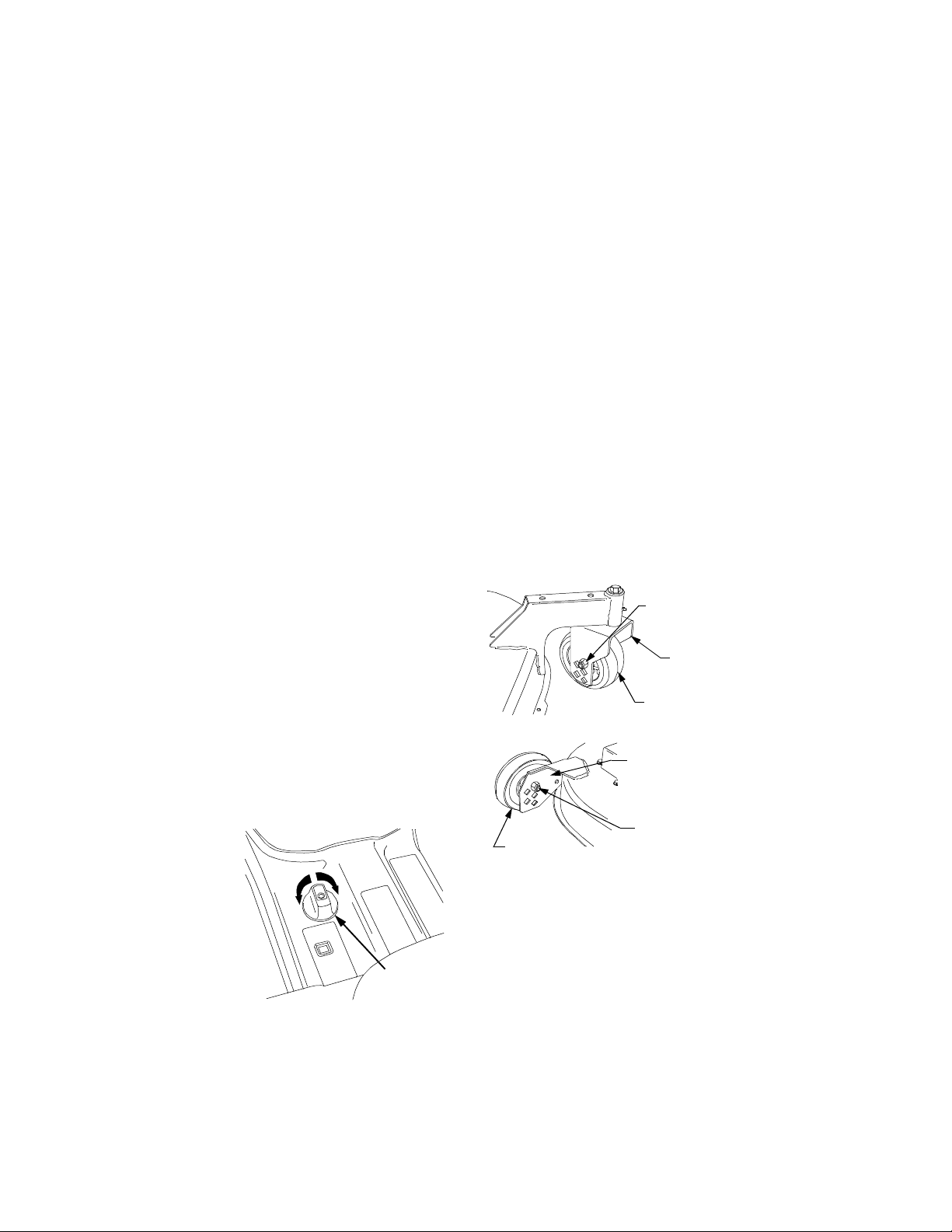
C. Setting the Cutting Height
The cutting height is set by using
either the deck height adjustment
knob to set the deck downstop
position or by positioning the caster/
gauge wheels in one of five settings.
Using Height Adjustment Knob
Each full rotation of the adjustment
knob equals approximately a 1/4 inch
adjustment in the deck height setting,
and there are four detent positions per
rotation. Initially set the height adjustment knob as follows (Refer to Figures
33 and 34):
1. Using the tractor lift system, fully
raise the deck. Raise the caster
and gauge wheels to their highest
position.
2. Fully lower the deckstop by continuously turning the adjustment
knob counterclockwise.
3. Lower the deck to the desired
height setting, then turn the adjustment knob clockwise until it
stops turning freely. Turn the knob
to the nearest detent position.
4. Reposition the caster and gauge
wheels so that they either just contact or are 1/2 inch above the
ground.
5. For subsequent minor adjustments from this position, fully raise
the deck and turn the adjustment
knob as necessary to attain the
desired height setting (one full turn
equals approximately 1/4"). Reposition the caster and gauge wheels
as necessary.
LOWER
RAISE
Height
Adjustment
Knob
Figure 33
Using the Caster/Gauge Wheels
The holes in the caster wheel yokes
equate to height settings ranging from
approximately 1-1/2” (top hole) to 3-1/ 2”
(lower hole), with the holes positioned at
1/2” increments. Set the cutting height
as follows (See Figure 34):
1. Using the tractor lift system, fully
raise the deck. Fully lower the
deckstop by continuously turning
the adjustment knob counterclockwise.
2. Remove the hex cap screws and
nylon lock nuts from the front
caster wheels and yokes .
3. Align the caster wheels with the
holes in the yoke that correspond
to the desired cutting height.
Insert the hex cap screws and
secure with the nylon lock nuts.
4. Remove the hex cap screws and
nylon lock nuts from the rear
gauge wheels and brackets.
Hex Cap
Screw &
Lock Nut
Caster
Wheel
Yoke
Front
Caster
Wheel
Gauge
Wheel
Bracket
Hex Cap
Rear
Gauge
Wheel
Figure 34
5. Note the hole position of the front
caster wheels and align the rear
gauge wheels with the matching
holes in the gauge wheel brackets. Insert the hex cap screws
and secure with the nylon lock
nuts.
Screw &
Lock Nut
38
Page 39

6. If a cutting height in excess of 31/2” is desired, it will be necessary to set the cutting height by
utilizing the height adjustment
knob. The wheels will not contact
the ground.
Removal and Installation of
Mower Deck
Place the tractor and mower deck on a
firm, level surface having enough room
to accomodate the deck and tractor.
WARNING: Before beginning removal, or installation
of the deck, place the PTO
switch in the “OFF” position, engage the parking
brake lever, and turn the
ignition key to “OFF” position and remove the key.
Use care not to cut yourself on the sharp blades.
A. Removal of Deck
1. Adjust the front caster wheels and
rear gauge wheels to their highest
setting (lowest deck height
setting). Refer to Figure 34.
2. If necessary, turn the height adjusment knob counterclockwise to
lower the deck downstop. Then
use the tractor lift system to lower
the deck to the ground.
3. Support the deck drive shaft to
prevent it from dropping; then pull
the auto-lok collar rearward and
slide the drive shaft off of the PTO
shaft (See Figure 35).
PTO Shaft
Auto-Lok
Collar
Figure 35
Deck Drive
Shaft
4. Pull outward and cock the deck
support pins in the rear deck
hanger brackets so that both
spring-loaded pins are held in the
disengaged position against the
inner surface of the deck brackets (See Figure 36).
LH Lift
Link
Figure 36
NOTE: The LH lift link must be raised
to provide clearance for sliding the
mower deck under, or out from under,
the tractor.
5. Refering to Figures 37A through
37D, lock the LH lift link in its deck
installation/removal position as
follows:
• Holding the LH lift rod downward,
lift upward on the release tab of
the lift stop bracket while raising
the rearward end of the lift link to
align its slot with the notch of the
LH lift rod (See Figures 37A and
37B).
• Swing the LH lift rod forward until
fully to the front of the lift link slot
(See Figures 37C and 37D).
Inner Hole
Deck
Support
Pin
Rear Deck
Bracket
39
Page 40
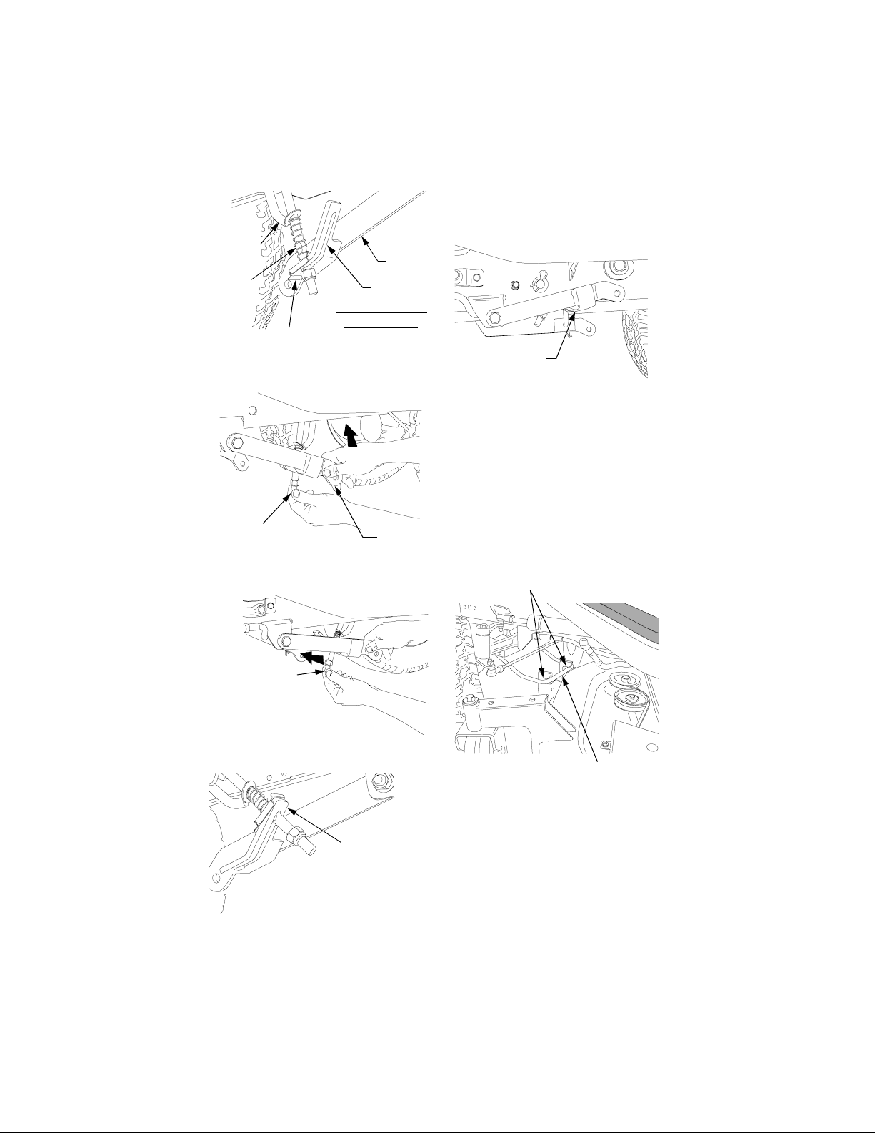
LH Lift
Rod
Notch
Lift Stop Bracket
Release Tab
Hold
Down
VIEWED FROM
RIGHT SIDE
Figure 37A
Figure 37B
LH Lift
Link
Slot
Lift
Upward
6. Use the hydraulic lift to fully raise
the LH and RH lift links (See Figure 38). Stop the engine.
Left Lift Link
Fully Raised
Figure 38
7. Roll the deck forward to disengage the front lift rod from the
slots of the front roller bracket
(See Figure 39). Hold the front lift
rod upward and slide the deck
rearward until the lift rod rests on
top of the roller bracket, forward
of the slots.
Front Roller
Bracket Slots
Swing Lift
Rod Forward
VIEWED FROM
RIGHT SIDE
Figure 37C
Figure 37D
LH Lift Link
Locked
Front Lift Rod
Figure 39
8. From the front of the tractor, pull
the center of the quick latch rod
downward t o release the front li ft
bracket/rod assembly. Slide the
front lift bracket assembly from
the latch receiver slots of the tractor (See Figure 40).
40
Page 41
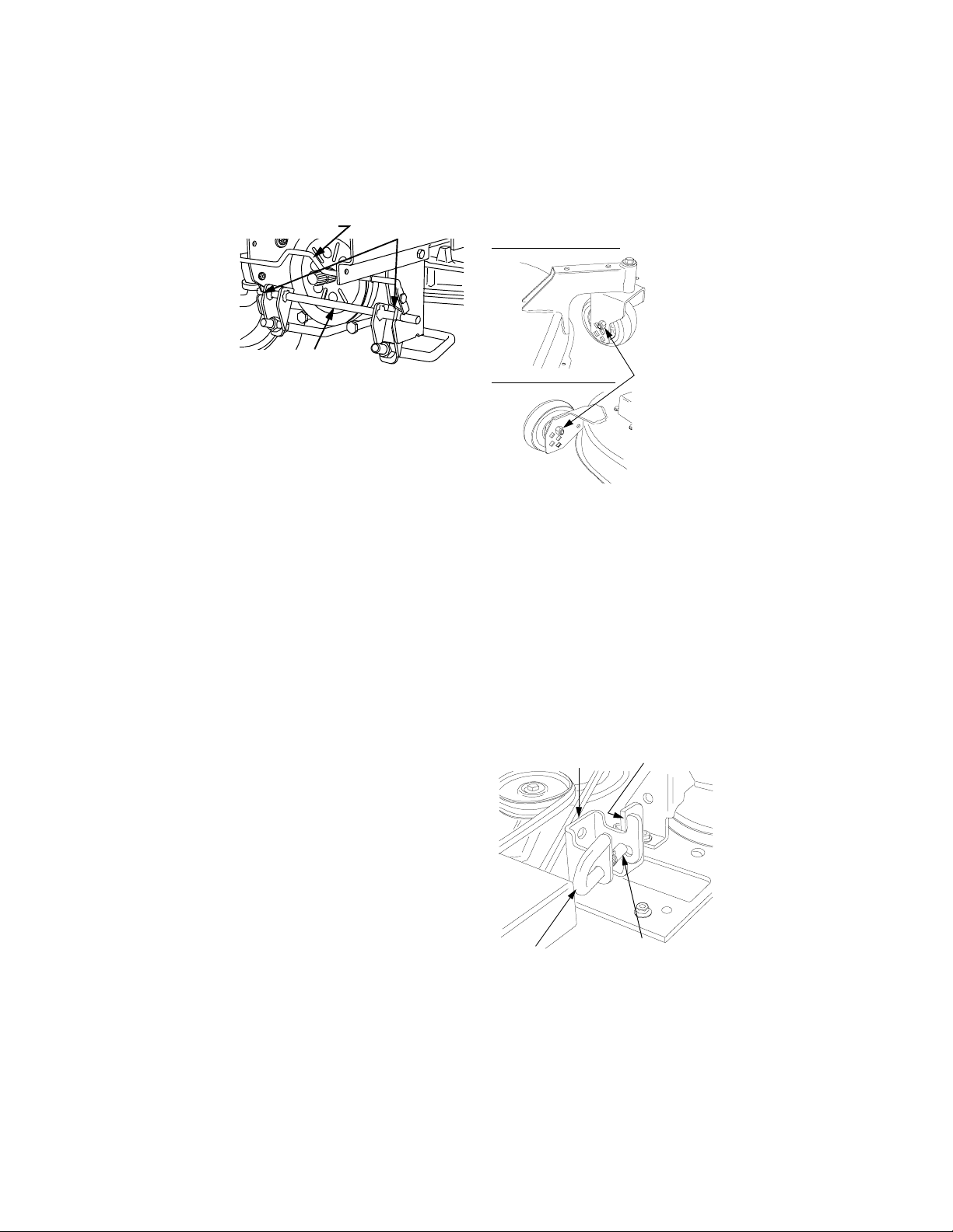
Quick Latch Rod
Latch Receiver
Slots
setting (lowest deck setting). See
Figure 41.
Front Caster Wheel
Front Lift
Brack et/Rod Ass’y.
Figure 40
9. From the left side of the tractor,
slide the mower deck out from
under the tractor.
B. Installation of Mower Deck
NOTE: The LH lift link must be raised
to provide clearance for sliding the
mower deck under, or out from under,
the tractor.
1. To ensure the tractor lift links can
be fully lowered, lower the deck
downstop by continuously turning
the height adjustment knob
counterclockwise
2. If not already done, lock the LH lift
link in its deck installation/removal
position as follows: (Refer to Figures 37A through 37D).
• Holding the LH lift rod downward,
lift upward on the release tab of the
lift stop bracket while raising the
rearward end of the lift link to align
its slot with the notch of the LH lift
rod (See Figures 37A and 37B).
• Swing the LH lift rod forward until
fully to the front of the lift link slot
(See Figures 37C and 37D).
3. Start the tractor and use the
hydraulic lift to fully raise the left
lift link. Stop engine.
4. Check the caster wheel and
gauge wheel settings on the deck.
If necessar y, remove t he hex cap
screws and nylon lock nuts, and
adjust the wheels to their highest
Rear Gauge Wheel
Figure 41
Upper Hole
5. From the left side of the tractor,
slide the deck under the tractor
until the slots of the LH and RH
rear deck brackets align approximately with the tractor lift links
(See Figure 42).
6. Pull outward and cock the deck
support pins in the rear deck
brackets so that both springloaded pins are hel d in the di sengaged position against the inner
surface of the deck brackets
(See Figure 42).
Rear Deck
Bracket
Deck
Support Pin
Figure 42
Slot
Pin Locked in
Disengaged
Position
41
Page 42
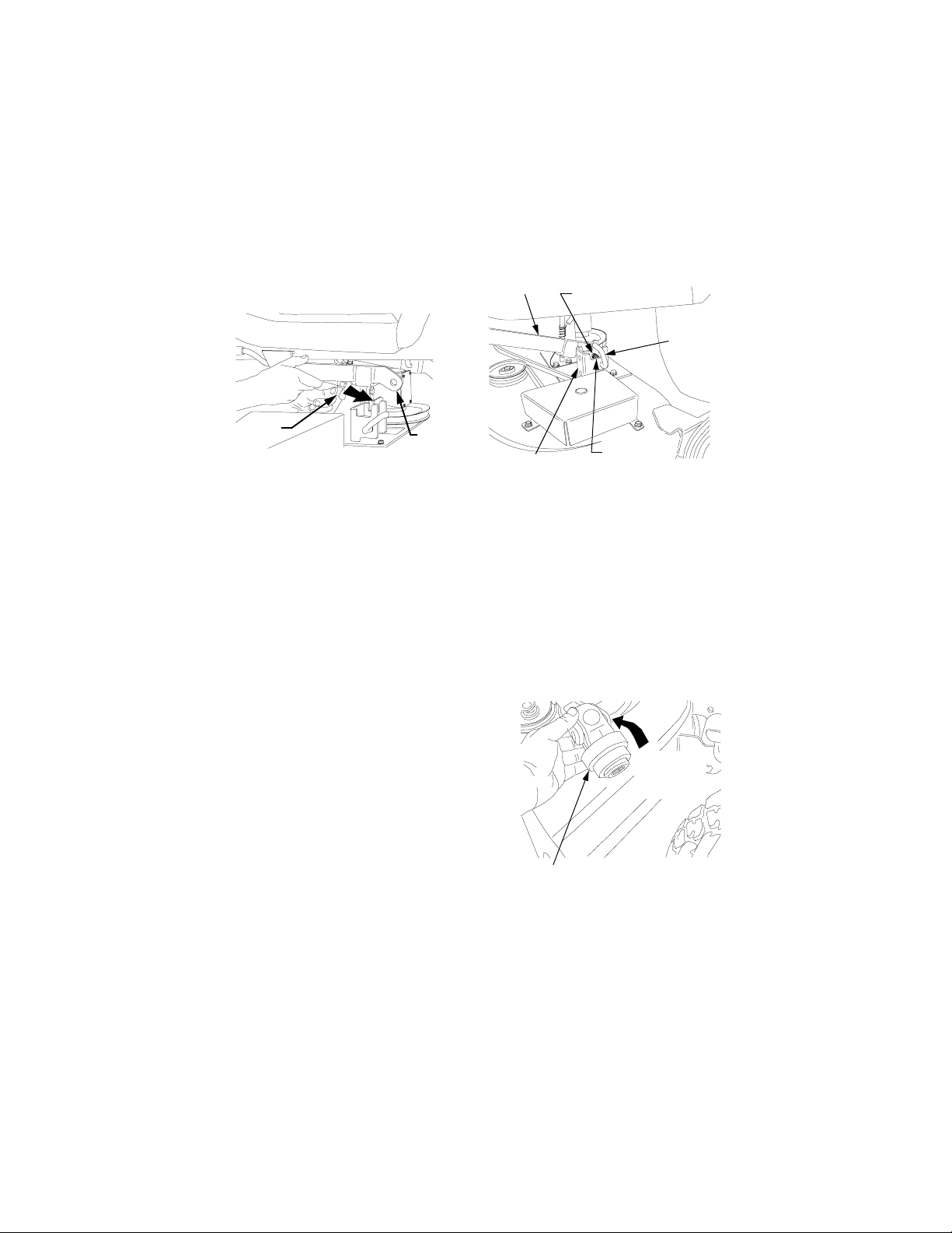
7. Use the tractor lift system lever to
lower the lift links.
8. Unlock the left lift link by sliding
the left lift rod fully rearward in the
slot of the lift link (See Figure 43).
spring tension wil l push the pins
inward and, if aligned, through
the hole in each implement lift
link (See Figure 44).
Lift Link
Through
Inner Hole
Deck
Support
Pin
LH Lift
Rod
Figure 43
LH Lift
Link
9. From the front of the tractor, slide
the outer pins of the front lift
bracket into the latch receiver
slots of the tractor. Press the lift
bracket rearward until both sides
are firmly captured in the latch
receivers by the quick latch rod
(See Figure 40).
10. From the side of the tractor, raise
the front lift rod and roll the deck
forward until the lift rod aligns with
slots of the deck front roller
bracket. Lower the lift rod into the
front roller bra cket slots and sl ide
the deck rearwar d to engage the
lift rod fully forward in the slots of
the roller bracket (See Figure
39).
11. Guide the LH and RH lift links into
the slots of the rear deck brackets and release the deck support
pins by aligning with the inner
holes of the deck brackets (See
Figure 44). Make certain the handles of the support pins are within
the notches at the top of the rear
deck brackets.
12. Maneuver each side of the deck
slightly to align the support pins
with the holes of the lift links. The
Rear Deck
Notch
Bracket
Figure 44
NOTE: If unable to align the support
pins with the lift link holes, loosen the
two hex lock nuts on the front lift rod to
allow the deck to be moved farther
rearward.
13. Compress the auto-lok collar of
the deck drive shaft rearward,
then cock to lock the collar in the
released position (See Figure 45).
Compress
Then Cock
To Lock
Auto-Lok
Collar
Figure 45
NOTE: If you do not lock the drive
shaft auto-lok collar in the released
position ( step 13), it will be necessar y
to compress and hold the collar
rearward when connecting the shaft
(step 14).
42
Page 43

14. Slide the deck drive shaft fully
onto the PTO shaft of the tractor
(See Figure 46). The auto-lok collar of the drive shaft should snap
into the locked position when the
shaft is properly positioned on the
PTO shaft.
PTO Shaft
Collar
Figure 46
15. Refer to Deck Leveling Adjustments at the beginning of this
section for mower deck leveling
procedures.
Deck Drive
ShaftAuto-Lok
grass. If necessary, remove the RH
and LH belt covers by removing the
six hex nuts and lock washers.
The cutting blades must be kept sharp
at all times.
Sharpen the cutting edges of the
blades evenly so that the blades
remain balanced and the same angle
of sharpness is maintained. If the
cutting edge of a blade has been
sharpened to within 5/8 inch of the
wind wing radius (See Figure 47), it is
recommended that new blades be
installed. New blades are available at
your authorized dealer.
Wind
Wing
Figure 47
5/8" From
Radius
Mower Deck Maintenance
WARNING: Before performing any maintenance procedures on the deck, place
the PTO switch in the “OFF”
position, engage the parking brake lever, and turn the
ignition key to “OFF” position and remove the key.
Use care not to cut yourself on the sharp blades.
A. Cleaning and Blade Care
Clean the underside of the mower
deck at the end of the mowing season
or when buildup of cut material on the
underside is noticed.
Once a month remove any
accumulated grass clippings from
around the spindle pulleys and V-belt.
More often when mowing tall, dry
When removing th e blades, use a 11/8 inch wrench to hold the head of
the spindle bolt while loosening the
hex flange nut securing the blade. A
block of wood may be placed
between the deck housing and the
cutting edge of the blade to assist i n
removal of the hex flange nut (See
Figure 48).
Hex Nut
Wood Block
1-1/8" Wrench
1-1/8" Wrench
Figure 48
in Position
43
Page 44
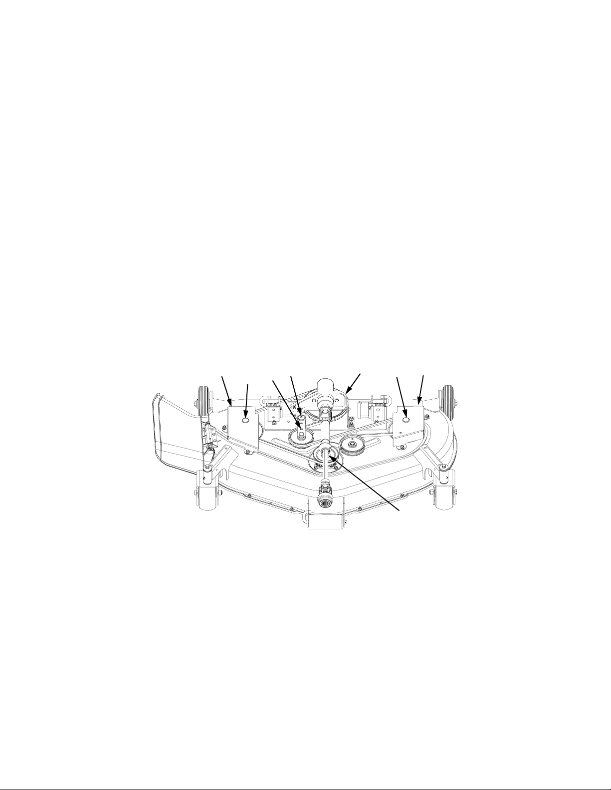
When reinstalling the blades, be sure
they are installed so that the wind
wings are pointing upward toward the
top of the deck. Tighten the nuts to 90
to 110 ft-lbs. (122 to 149 N·m).
After replacing the blades, apply
grease to the exposed threads at the
bottom of the spindle bolts to prevent
rust buildup.
B. Lubrication
After every 10 hours of operation and/
or before putting the deck into winter
storage, lubricate the spindle
assemblies and the spindle belt idler
arm using 251H EP grease or an
equivalent No. 2 multipurpose lithium
grease. The lube fitting for the outer
spindles can be accessed by removing
the button plugs in the belt covers.
Use grease liberally. Excess grease
will be expelled from the upper spindle
seals. When the spindle is fully
greased, the expelled grease will
cause the top spindle seal to give off a
muffled crackling noise (Refer to
Figure 49).
Apply grease to all other lube fittings
after every 50 hours of operation.
Refer to the MAINTENANCE CHART
and LUBRICATION ILLUSTRATION
in Section 9
1
1.
Belt Covers
2.
Button Plugs - Access to
2&5
3
Spindle Lube Fittings
Idler Arm - w/Square Hole
3.
4
4.
5.
Figure 49
6
2&5
1
5
Idler Arm Lube Fitting
Spindle Assembly Lube
Fitting
Gear Box Mounting Bracket6.
44
Page 45
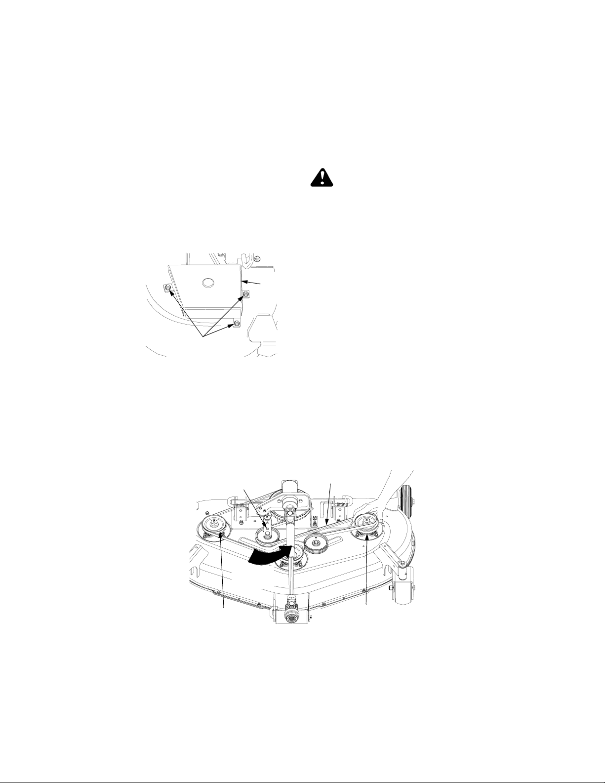
C. Spindle Belt Replacement
A worn spindle belt will affect the
quality of cut from the mower deck and
should be replaced. Referring to
Figures 49 thru 53, replace the spindle
belt as follows:
NOTE: Clean any accumulated grass
clippings from the mower deck before
beginning belt replacement .
Remov e Spindle Belt
Belt
Cover
Hex Nuts and
Lock Washers
Figure 50
1. Remove the RH and LH belt covers by removing the six hex nuts
and lock washers (See Figure 50).
2. Note the routing of the spindle
belt to help ensure proper installation of the new belt.
WARNING: The idler arm
and movable flat idler pulley are under spring
tension. To prevent possible injury, use caution
when handling the idler arm
and pulley.
3. Insert a 3/8” drive ratchet or
breaker bar into the square hole
of the idler arm (Refer to Figure
51).
4. Using the ratchet (breaker bar) for
leverage, pivot the idler arm
toward the left side of the deck to
loosen tension on the belt: then
roll the belt off either the LH or
RH spindle pulley (See Figure
51).
5. Remove the two hex flange lock
nuts and carriage bolts securing
the left side of the gear box
mounting bracket to the deck
(See Figure 52).
Square Hole
in Idler Arm
Pivot
Idler Arm
RH Spindle
Pulley
Spindle Belt
LH Spindle
Pulley
Figure 51
45
Page 46
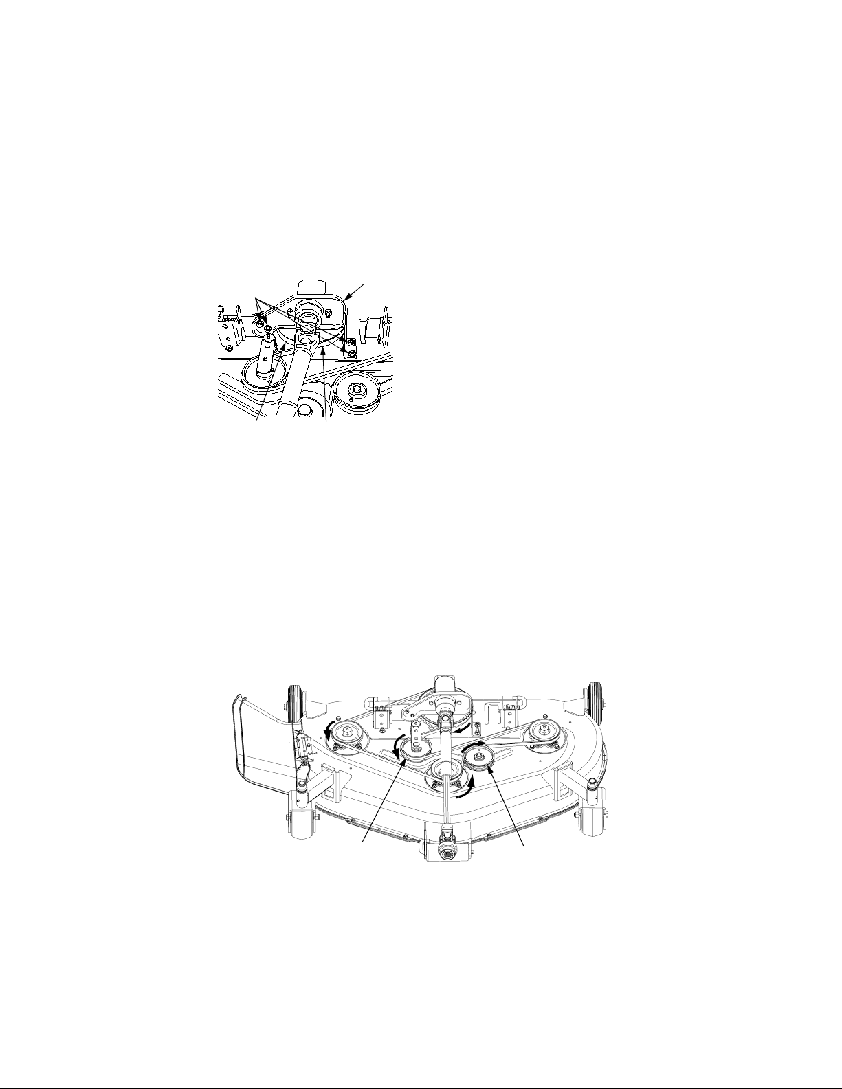
6. Remove the two hex flange lock
nuts and carriage bolts securing
the right side of the gear box
mounting bracket to the deck
plate (See Figure 52).
Carriage Bolts
and Hex Flange
Gear Box
Mtg. Bracket
Lock Nuts
Drive Pulley
Spindle Belt
Figure 52
7. Lift the gear box/mounting
bracket assembly and slide the
belt off and underneath the drive
pulley.
8. Slip the belt under the moveable
flat idler pulley (See Figure 53)
and remove from the deck.
Install new spindle belt
1. Lift the gear box/mounting
bracket assembly to install the
belt around the rear and left side
of the drive pulley, and through
the center opening of the mounting bracket (See Figure 52).
2. Secure the gear box mounting
bracket with the four carriage
bolts and hex flange lock nuts.
3. Slip the belt under the moveable
flat idler pulley and route the belt
as follows (Refer to Figure 53):
• around the right spindle pulley
• around the front of the center
spindle pulley
• around the rear of the fixed flat
idler pulley to the left spindle
pulley
• Route the backside of the belt
around the rear and right side of
the movable flat idler pulley
4. After making certain the belt is
properly engaged in each pulley,
insert the 3/8” drive ratchet
(breaker bar) into the idler arm
and pivot the movable flat idler
pulley toward the left side of the
deck to allow the spindle belt to
be rolled onto the left hand spindle pulley. Refer to Figure 51.
5. Install the belt covers a nd secure
with the hex nuts and lock
washers.
Movable
Flat Idler
Pulley
Fixed
Flat Idler
Pulley
Figure 53
46
Page 47
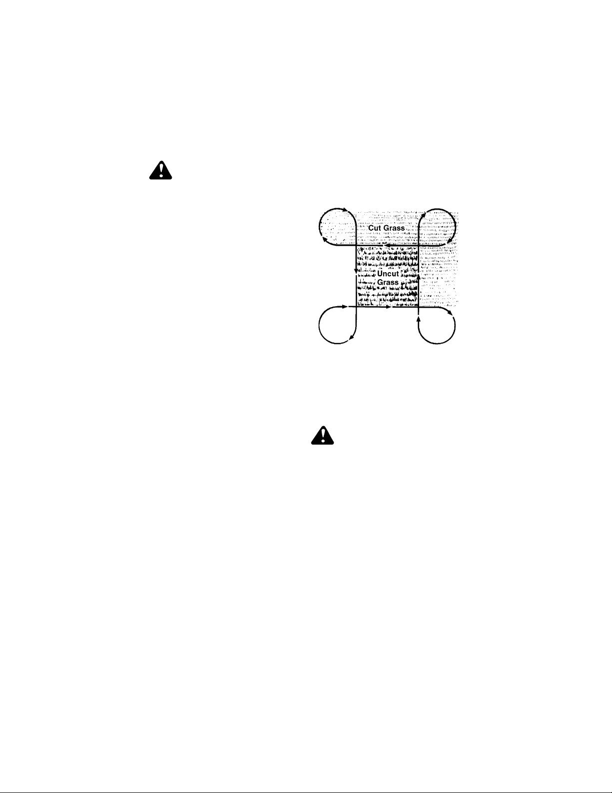
Mowing With Deck
A. Normal Mowing
WARNING: To avoid possible injury, never direct the
discharge of material
toward bystanders or allow
anyone near the machine
while in operation.
Although the area has been
supposedly cleared of foreign objects, small objects
may be picked up and discharged by the mower.
For best results it is recommended
that the first two laps should be cut
with the discharge thrown towards the
center. After the first two laps, reverse
the direction to throw the discharge to
the outside for the balance of cutting.
This will give a better appearance to
the lawn.
Do not cut the grass too short, as the
mower will tend to scalp the grass.
Short grass invites weed growth and
yellows quickly in dry weather.
Mowing should be done with the
engine at full throttle. Do not mow at
high ground speed.
During certain times of the year and
under some conditions, the mower
may leave s treaks of uncut grass.
Streaking may occur when attempting
to mow heavy weeds and tall grass.
Under these conditions it may be
necessary to go back over the cut
area a second time to get a clean cut.
The following practices will help
eliminate streaking:
1. Mow the area more often so the
grass doesn’t get too tall and
heavy.
2. Operate the tractor at full throttle
and slower forward speeds.
3. Keep the blades sharp and
replace worn blades.
4. Follow the mowing pattern shown
in Figure 54.
Figure 54
B. Mowing With Mulching
Option
Installation of Mulching Plug
WARNING: Before installing
the mulching plug, place the
PTO switch in the “OFF”
position, engage the brake
pedal lock, turn the ignition
key to the “OFF” position.
1. If the mow er de ck ha s be en us ed,
clean any buildup of grass
clippings from the chute opening
of the deck housing.
2. Lift and hold the chute deflector in
the upward position (Refer to Figure 55).
3. Positi on the m ulchi ng plu g so t hat
the retaining lip on the backside
of the plug parti ally inter locks with
the lower edge of the deck chute
opening; then rotate the top of the
47
Page 48

plug upward so that the hooks
engage the deflector hinge rod
(See Figure 55).
4. Push the mulching plug fully
downward and lower the chute
deflector.
5. To remove the mulching plug,
raise the chute deflector and lift
the mulching plug upward, then
outward to disengage from the
deck. Lower the chute deflector.
Deflector Hinge Rod
Lower Edge of
Chute Opening
Chute Deflector
Hinge Rod
Hooks
Chute Deflector
Retaining
Lip
Mulching
Plug
Figure 55
Mulching Operation
1. Do not cut wet grass. For
effective mulching do not cut wet
grass. Wet grass sticks to the
underside of the deck, preventing
proper mulching and dispersal of
grass clippings.
2. Cut no more than 1/3 the length
of the grass. When mulching
long grass, it may be necessary
to mow twice, lowering the deck
another 1/3 of the length for the
second cut, and perhaps cutting
in a different pattern. Overlap the
cut on each pass to help clean up
any heavy clippings left on the
lawn.
3. Use a slow ground speed.
Adjust ground speed so clippings
can be evenly dispersed into the
lawn. When cutting heavy grass,
it may be necessary to use a
slower ground speed in order to
get a well mulched cut.
4. Always operate the tractor at
full throttle. To obtain the best
cut and do the most effective job
of mulching, the engine should be
run at full throttle.
5. Clean underside of deck. Be
certain to clean the underside of
the deck often to avoid a buildup
of grass clippings, which will prevent proper mulching.
48
Page 49

SECTION 12: TROUBLE SHOOTING
Possible Cause Possible Remedy
Hard To Start
No fuel in fuel tank or carburetor Fill the tank with fuel. Check the fuel line,
Fuel ine or carburetor clogged Clean the fuel line and carburetor with a
Fuel filter plugged Replace
Water in fuel Drain the fuel tank and carburetor. Use new
Choked improperly. Flooded engine Follow the starting instructions.
Defective ignition or loose wiring Check the wiring, spark plugs or fuse.
Defective battery Check and service. Refer to “BATTERY.”
Spark plug dirty or improperly gapped Clean, adjust the gap to .030-inch or replace
Engine Operates Irregularly or Knocks
Engine incorrectly timed See your authorized dealer.
Spark plug dirty; wrong gap or wrong type Clean, reset the gap or replace
Poor or weak spark Check the spark plugs and wiring.
Carburetor setting incorrect See your authorized dealer.
Poor grade fuel or water in fuel Drain and use a good grade of clean fuel.
Engine overheating Refer to “MAINTENANCE.”
Engine valves at fault See your authorized dealer.
Engine smokes See your authorized dealer.
Oil level rises due to fuel in the crankcase See your authorized dealer.
Air filter becomes oil and fuel soaked See your authorized dealer.
Engine leaks oil See your authorized dealer.
Misfiring See your authorized dealer.
Other engine problems See your authorized dealer.
Excessive oil in air cleaner Be sure that oil dipstick is f ully seated, oil fill
PTO Clutch Will Not Engag e
Reverse pedal is partially depressed Depress brake pedal.
Vacuum actuator not energized Check PTO switch and connections, check
Vacuum leak Check vacuum lines.
Lack of Power
Air cleaner clogged Service the air cleaner element. Refer to
Engine overload Reduce the load.
Engine overheated Make sure the air intake screen, shrouding,
carburetor and fuel filter.
commercial carburetor cleaner.
fuel and dry the sparks plugs.
the plug.
cap is tight, and all excess oil is squeezed out
of the pre-cleaner.
for worn or broken wiring.
“MAINTENANCE.”
engine fins, side panels, dash intake screen
and grille are free of accumulated dirt and
debris. Refer to “MAINTENANCE.”
49
Page 50

Possible Cause Possible Remedy
Fuel tank air vent clogged Remove obstruction from the vent in the fuel
Air leakage between carburetor and engine Remo ve air cleaner. Tighten the carburetor
Incorrect timing or faulty ignition See your authorized dealer.
Brake dragging Adjust the brakes. Refer to “ADJUST-
Insufficient cooling air — dirt or debris clogging the: air intake screen • shrouds • cooling fins • side panels • dash intake screen •
or grille
Oil level incorrect Engine oil level must not be over the “FULL”
tank cap.
and manifold mounting hardware. Replace
any damaged parts as indicated in “MAIN-
TENANCE.”
MENTS.”
Keep the air intake area, side panels, grille,
dash intake screen and cooling fins clean.
Refer to “MAINTENANCE.”
mark or below the “ADD” mark on dipstick.
Refer to “MAINTENANCE.”
50
Page 51

SECTION 13: OPTIONAL EQUIPMENT
When you purchased your tractor, you probably had it completely equipped for
your particular needs at that time. However, later you may wish to obtain
optional equipment or accessories. These items and other allied equipment can
be purchased from, and installed by, your authorized Cub Cadet dealer.
This tractor can be used for many different types of work, and because it is
called on to operate under many different conditions, a variety or equipment is
available to adapt it to the requirements of the user. Refer to the optional
equipment chart below for a list of products available at the time of printing.
Description Model Number
(1)
Mechanical Angling Kit
Hydraulic Angling Kit
(1)
Front Hitch System 190-343-100
Grass Collection System 190-212-100
54 Inch Blade
Snow Thrower
(2)
(1)
3 Point Hitch 190-207-100
Hydraulic Tiller
(3)
(1) Requires front hitch system 190-343-100.
(2) Requires front hitch system 190-343-100. Can use optional Mechanical
Angling Kit 190-171-100 or Hydraulic Angling Kit 190-288-100.
(3) Requires 3 point hitch 190-207-100
190-171-100
190-288-100
190-352-100
190-353-100
190-004-100
51
Page 52

SECTION 14: SPECIFICATIONS
Engine
Manufacturer . . . . . . . . . . . . . . . . . . . . . . . . . . . . . . . . . . . . . . . . . Kohler
Horsepower . . . . . . . . . . . . . . . . . . . . . . . . . . . . . . . . . . . . . . . . . . . . . 20
Cylinders . . . . . . . . . . . . . . . . . . . . . . . . . . . . . . . . . . . . . . 2 (Command)
Cooling . . . . . . . . . . . . . . . . . . . . . . . . . . . . . . . . . . . . . . . . . . . . . . . . Air
Fast Idle Speed . . . . . . . . . . . . . . . . . . . . . . . . . . . . . . . . . . . . . . . . 3600
Slow Idle Speed . . . . . . . . . . . . . . . . . . . . . . . . . . . . . . . . . . . . . . . 1200
Displacement (cubic inches) . . . . . . . . . . . . . . . . . . . . . . . . . . . . . . . . 38
Compression Ratio . . . . . . . . . . . . . . . . . . . . . . . . . . . . . . . . . . . . . 8.5:1
Spark Plug . . . . . . . . . . . . . . . . . . . . . RC12YC (Champion or equivalent)
Oil Filter . . . . . . . . . . . . . . . . . . . . . . . . . . . . . . . . . . . . . . . . . . . .Cartridge
Crank Case Capacity . . . . . . . . . . . . . . . . . . . . . . . . . . . . . . . . . . . 64 oz.
Electrical System
Charging System . . . . . . . . . . . . . . . . . . . . . . . . . . . . Flywheel-Alternator
Capacity . . . . . . . . . . . . . . . . . . . . . . . . . . . . . . . . . . . 15 Amp Regulated
Battery Type . . . . . . . . . . . . . . . . . . . . . . . . . . . . . . . . . . . . . . Lead Acid
Battery Cold Cranking Amps at 0° F . . . . . . . . . . . . . . . . . . . . . . . . . 435
Ignition . . . . . . . . . . . . . . . . . . . . . . . . . . . . . . . . . . . . . . . . . . . . . . Battery
Fuses (auto type) . . . . . . . . . . . . . . . . . . . . . . . . . . . . . . . . . . . . 25 amp
Battery Voltage . . . . . . . . . . . . . . . . . . . . . . . . . . . . . . . . . . . . . . 12 Volts
Fuel System
Fuel Tank Capacity (gallons) . . . . . . . . . . . . . . . . . . . . . . . . . . . . . . . 4.5
Type of Fuel . . . . . . . . . . . . . . . . . . . . . . . . . . . . . . . . . . . . . . . Unleaded
Fuel Filter . . . . . . . . . . . . . . . . . . . . . . . . . . . . . . . . . . . . . . . . . . . . In-line
Drive Train
Transmission . . . . . . . . . . . . . . . . . . . . . . . . . . . . . . . . . . . . . Hydrostatic
Transmission Oil . . . . . . . . . . . . . . . Cub Cadet Drive System Fluid Plus
Transmission Oil Capacity . . . . . . . . . . . . . . . . . . . . . . . . . . . . . 5.5 Qts.
Tires
Front (inches) . . . . . . . . . . . . . . . . . . . . . . . . . . . . . . . . . . . . 16 x 6.5 - 8
Rear (inches) . . . . . . . . . . . . . . . . . . . . . . . . . . . . . . . . . . . . . 23 x 9.5 - 12
Dimensions and Weight
Wheelbase . . . . . . . . . . . . . . . . . . . . . . . . . . . . . . . . . . . . . . . . . . 49.5 in.
Overall Length . . . . . . . . . . . . . . . . . . . . . . . . . . . . . . . . . . . . . . . 72.25 in.
Overall Width (w/o Mower Deck) . . . . . . . . . . . . . . . . . . . . . . . . . . . 42 in.
Overall Width (w/Mower Deck - Chute raised) . . . . . . . . . . . . . . . . 49 in.
Height . . . . . . . . . . . . . . . . . . . . . . . . . . . . . . . . . . . . . . . . . . . . . . 43.6 in.
Weight (w/Mower Deck) . . . . . . . . . . . . . . . . . . . . . . . Approx. 1003 lbs.
Turning Radius . . . . . . . . . . . . . . . . . . . . . . . . . . . . . . . . . . . . . . . . 27 in.
Ground Clearance . . . . . . . . . . . . . . . . . . . . . . . . . . . . . . . . . . . . . . . 6 in.
Brakes
Type . . . . . . . . . . . . . . . . . . . . . . . . . . . . . . . . . . . . . . . . . . External Disk
Parking . . . . . . . . . . . . . . . . . . . . . . . . . . . Foot Actuated - Hand Locked
PTO Clutch
Type . . . . . . . . . . . . . . . . . . . . . . . . . . . . . . . . . . . . . . . . . .E-Vac System
Attachment Lift System
Type . . . . . . . . . . . . . . . . . . . . . . . . . . . . . . . . . . . . . . . . . . . . . Hydraulic
52
Page 53
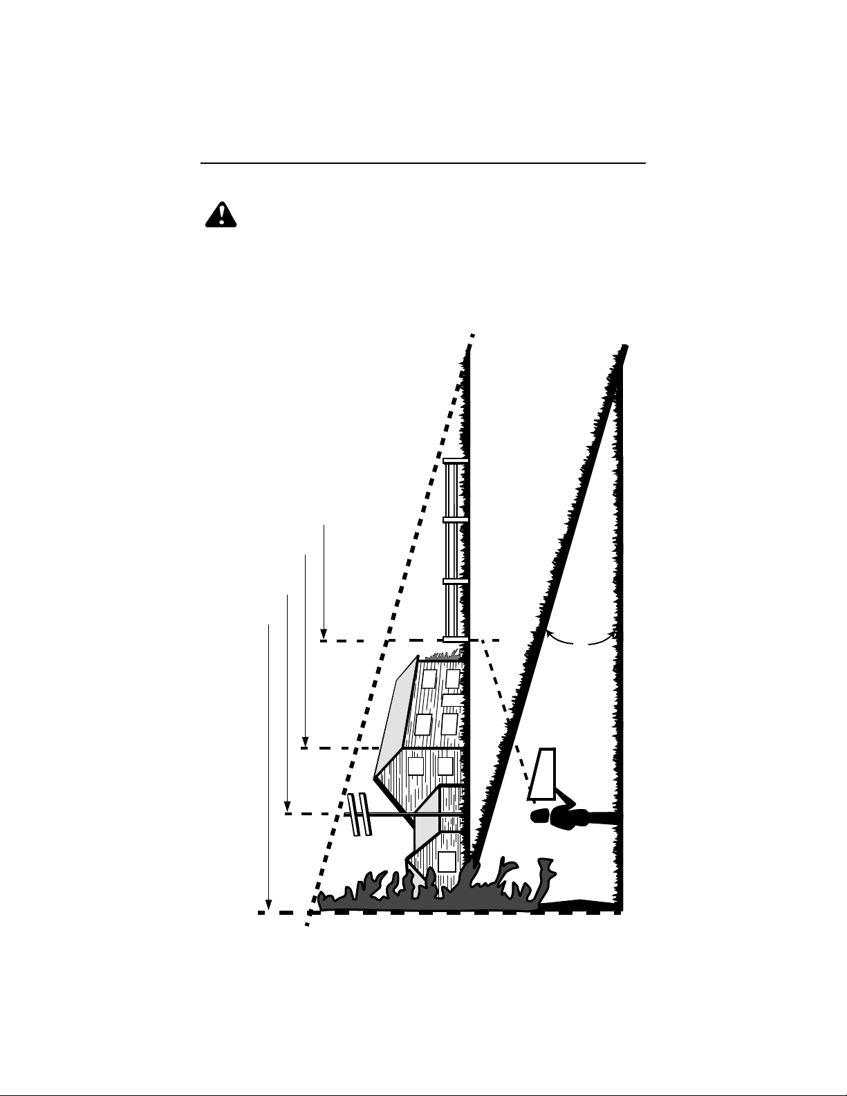
SECTION 15: SLOPE GAUGE
WARNING: Do not mow on inclines with a slope in excess of 15
degrees (a rise of approximately 2-1/2 feet every 10 feet). A riding
mower could overturn and cause serious injury. If operating a walkbehind mower on such a slope, it is extremely difficult to maintain
your footing and you could slip, resulting in serious injury.
• Operate RIDING mowers up and down slopes, never across the face of slopes.
• Operate WALK-BEHIND mowers across the face of slopes, never up and down
slopes.
E
P
O
L
S
°
5
1
A
G
N
I
T
N
E
S
E
R
P
E
R
,
E
N
I
L
D
E
T
15°
SIGHT AND HOLD THIS LEVEL WITH A VERT ICAL TREE
OR A FENCE POST
A CORNER OF A BUILDING
A POWER POLE
T
O
D
N
O
D
L
O
F
USE THIS PAGE AS A GUIDE TO DETERMINE SLO PES WHERE YOU MAY NOT OPERATE SAFELY.
53
Page 54

54
Page 55

CUB CADET CORPORATION
MANUFACTURER’S ONE YEAR LIMITED WARRANTY
(COMMERCIAL USE)
The limited warranty set forth below is given by CUB CADET CORPORATION
(“CUB CADET”) with respect to new merchandise purchased and used in the
United States, its possessions and territories.
CUB CADET war ra nt s th is p r od uc t a ga i ns t d ef e cts in m a te ri al a nd w or k ma ns hip
for a period of one
original purchase and will , at its optio n, rep air or rep lac e
found to be defective in materia l or workma nship. This limit ed warranty shall only
apply if this product has been operated and maintained in accordance with the
Operator’s Manual furnished with the product, and has not been subject to
misuse, abuse, neglect, accident, improper maintenance, alteration, vandalism,
theft, fire, water or damage because of other peril or natural disaster.
Batteries and belts are subject to separate terms as follows:
a. Batteries have a one-year prorated limited warranty with 100%
replacement during the first three months. After three months, the
battery replacement credit is based on the months remaining in the
twelve (12) month period dating back to the original date of sale. Any
replacement battery will be warranted only for the remainder of the
original warranty period.
b. All belts are covered by a one (1) year limited warranty against defects
in material and workmanship.
HOW TO OBTAIN SERVICE: Warranty service is available, WITH PROOF OF
PURCHASE, THROUGH YOUR LOCAL AUTHORIZED CUB CADET DEALER.
To locate the dealer in yo ur area, plea se check for a l isting in t he Yellow Pages or
contact CUB CADET by calling 1-800-528-1009 or writing to P.O. Box 368023,
Cleveland, Ohio 44136-9 723.
This limited warranty does not provide coverage in the following cases
a. Routine maintenance items such as lubricants, filters, blade sharpening
and tune-ups, or adjustments suc h as brake adj us tme nts , clu tch adju stments or deck adjustments; and normal deterioration of the exterior finish due to use or exposure.
b. Normal wear parts or components, including blades, blade adapters,
grass bags, rider deck wheels, seats, snow thrower skid shoes, shave
plates and tires.
c. CUB CADET does not extend any warranty for products sold or export ed
outside of the United States of America, its possessions and territories,
except those sold through CUB CADET’S aut horize d channe ls of export
distribution.
No implied warranty, including any implied warranty of merchantability or
fitness for a particular purpose, applies after the applicable period of
express written warranty above. No other express warranty or guaranty,
whether written or oral, ex cept as mention ed abov e, give n by a ny perso n or
entity, including the dealer, with respect to any product shall bind CUB
CADET. During the period of the Warranty, the exclusive remedy is repair
or replacement of the product as set forth above. (Some states do not allow
limitations on h ow l ong an im pl ied w arra nty la sts, so the above limitation may not
apply to you.)
(1) year for commercial us ers, commencin g on the date of
, free of charge, any part
:
55
Page 56

The provisions as se t fort h in th is Warrant y pro vide the sole a nd exc lusive
remedy arising from the sale. CUB CADET shall not be liable for incidental
or consequential loss or damag es including, without limitation, to an y claim
for loss of profits, loss of savings or revenue, loss of the use of the
equipment or any associated equipme nt, facilities or service, dow ntime, the
claims or costs of third parties including c ustomers, and inj ury to property,
and further including expenses incurred for sub stitute or replac ement lawn
care services, for transportation or for related expenses, or for rental
expenses to temporarily replace a warranted product. (Some states do not
allow the exclusion or limitation of incidental or consequential damages, so the
above exclusion may not apply to you.)
In no event shall reco very of any kin d be greate r than the a mount of th e purc hase
price of the produ ct sold . Alteratio n of the s afety fe atures of the produc t shall vo id
this Warranty. Yo u a ssum e t he risk and liabili ty for los s, da ma ge, or injury to you
and your property and/or to others and their property arising out of the use or
misuse or inability to use the product.
This limited warranty shal l not ext end to any one othe r than the ori ginal purchaser
or original lessee.
How State Law Relates to this Warranty: This limited warranty gives you
specific legal rights, and you may also have other rights which vary from state to
state.
56
Page 57

CUB CADET CORPORATION
MANUFACTURER’S LIMITED WARRANTY
(RESIDENTIAL USE)
The limited warranty set forth below is given by CUB CADET CORPORATION
(“CUB CADET”) with respect to new merchandise purchased and used in the
United States, its possessions and territories.
CUB CADET war ra nt s th is p r od uc t a ga i ns t d ef e cts in m a te ri al a nd w or k ma ns hip
for a period of two (2) years for residential users, (one (1) year for commercial
users), commencing on th e date of original purchas e an d wil l, a t its option, repair
or replace, free of charge, any part found to be defective in material or
workmanship. This limited warranty shall only apply if this product has been
operated and maintai ned in accordanc e with the Opera tor’s Manual fu rnished with
the product, and has not been subject to misuse, abuse, neglect, accident,
improper maintenance, alteration, vandalism, theft, fire, water or damage
because of other peril or natural disaster.
Batteries and belts are subject to separate terms as follows:
a. Batteries have a one-year prorated limited warranty with 100%
replacement during the first three months. After three months, the
battery replacement credit is based on the months remaining in the
twelve (12) month period dating back to the original date of sale. Any
replacement battery will be warranted only for the remainder of the
original warranty period.
b. All belts are covered by a one (1) year limited warranty against defects
in material and workmanship.
3 Year Limited Warranty - PTO Clutch
CUB CADET warrants the power take off (“PTO”) clutch and mounting hardware
against defects in material and workmanship for a period of three (3) years
Series 2000 products manufactured after August 1, 1997 for residential users,
commencing on the date of o riginal pu rchase o r lease a nd CUB CADET will, a t its
option, re pair or re place
found to be defective in material or workmanship provided this product has been
operated and maintained as set forth above.
5 Year/500 Hour Limited Warranty
CUB CADET warrants the frame, front cast iron pivot axle and drive shaft on
Series 2000 and 3000 models against defects in material and workmanship for a
period of five (5) years or 500 hours, whichever occurs first
commencing on the date of o riginal pu rchase o r lease a nd CUB CADET will, a t its
option, repair or replac e
or workmanship provided this product has been operated and maintained as set
forth above. In addition to any other reason set forth herein, CUB CADET may
deny warranty coverage if the hour meter, or an y part thereof, is altered, modifie d,
disconnected or otherwise tampered with.
HOW TO OBTAIN SERVICE: Warranty service is available, WITH PROOF OF
PURCHASE, THROUGH YOUR LOCAL AUTHORIZED CUB CADET DEALER.
To locate the dealer in yo ur area, plea se check for a l isting in t he Yellow Pages or
contact CUB CADET by calling 1-800-528-1009 or writing to P.O. Box 368023,
Cleveland, Ohio 44136-9 723 .
, free of charge, any PTO clutch or mounting hardware
, for residential users,
, free of charge, any p art foun d to be defect ive in materi al
for
57
Page 58

This limited warranty does not provide coverage in the following cases:
a. Routine maintenance items such as lubricants, filters, blade sharpening
and tune-ups, or adjustments suc h as brake adj us tme nts , clu tch adju stments or deck adjustments; and normal deterioration of the exterior finish due to use or exposure.
b. CUB CADET does not extend any warranty for products sold or export ed
outside of the United States of America, its possessions and territories,
except those sold through CUB CADET’S aut horize d channe ls of export
distribution.
c. Normal wear parts or components, including blades, blade adapters,
grass bags, rider deck wheels, seats, snow thrower skid shoes, rubber
auger spir als, shave plates and tires.
No implied warranty, including any implied warranty of merchantability or
fitness for a particular purpose, applies after the applicable period of
express written warranty above as to the parts as identified. No other
express warranty or guaranty, whether writte n or oral, exc ept as me ntioned
above, given by any person or entity, including the dealer, with respect to
any product shall bind CUB CADET. During the period of the Warranty, the
exclusive remedy is repair o r replacemen t of the product as set forth above.
(Some states do not allow limitations on how long an implied warranty lasts, so
the above limitation may not apply to you.)
The provisions as set forth in this Warranty provide the sole and exclusive
remedy arising from the sales. CUB CADET shall not b e liable for incide ntal
or consequential loss or damages including, without limitation, expenses
incurred for substitute or replacement lawn c are services, f or transportation
or for related expenses, or for rental expenses to temporarily replace a
warranted product. (Some states do not allow the exclusion or limitation of
incidental or c onsequentia l damages, so the ab ove exclusio n or limita tion may n ot
apply to you.)
In no event shall reco very of any kin d be greate r than the a mount of th e purc hase
price of the produ ct sold . Alteratio n of the s afety fe atures of the produc t shall vo id
this Warranty. Yo u a ssum e t he risk and liabili ty for los s, da ma ge, or injury to you
and your property and/or to others and their property arising out of the use or
misuse or inability to use the product.
This limited warranty shal l not ext end to any one othe r than the ori ginal purchaser
or original lessee.
How State Law Relates to this Warranty: This limited warranty gives you
specific legal rights, and you may also have other rights which vary from state to
state.
58
Page 59

59
Page 60
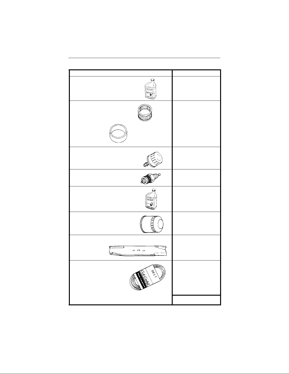
SECTION 16: QUICK REFERENCE PARTS
Description Part Number
Engine Oil
737-3030A (10W30)
737-3049 (5W30)
Air Filter
CARTRIDGE
KH-47-083-03
Engine Oil Filter
Spark Plug
Transmission Oil
T ransmission Oil Filt er
Mower D eck
Blades
Mower Deck Belts
FOAM
PRE-CLEANER
KH-24-083-02
KH-12-050-08
759-3336
Cub Cadet Drive
System Fluid Plus
737-3120 - Quart
737-3121 - Gallon
923-3014
44” Mower Deck
759-3939 (3)
PTO Belt (set of 2)
44” Mower Deck
954-3098 (1)
954-3084
 Loading...