

Page 1
Ownerts
Manual
5
H.P.
20"
Auger
Propelled
SnowThrower
Model
Number
317-262-1
00
Read Safety
Thank
you
lmportant:
Rules
and
Instructions
CarefullY
for
purchasing
an
American-built
product.
WARNING:
This unit
is equipped
with an
iRTeTnsl
cambustion
engine
and
should
not be used
on or
near any unlrDproved
forest-covered,
brush-covered
or
grass-covered
land unlessthe€DOnes
exhhuSlsystem
is equipped
with a_.spark
arrester
meeting applicable
local or state
laws
(if
any).
lf a spark
arrester
[s
gcort
iT\trould
be
maintained
in
effective
working order
by the
operator.
nanrrr
ln the
-State
of bahfornia
the
above
is required by
law
(Secti
on
4442 of
the Cai'i'*
;blic
Resources
Codet
Other
states
may
have
similar
laws.
Federal
laws apply on
federal
lands.
A spark arrestirE
..1'
muffler is
ava
lable
through
your
nearest authorized
service dealer.
CUB
CADET
CORPORATTON
.
P.O.
BOX 368023
.
CLEVELAND,
OHIO
44136-9723
Page 2
BLE OF
CONTEN
CONTENT
Chokc
Control
PAGE
Page 3
-r
1[
wanrurr.rc
Your
snow
thrower was
built to be operated according
to
the
rules for
safe
operation in this manual.
As with any
type
of
TRAINING
MAINTAINING
SAFETY
This
symbol
points
out
important
safety instructions
which, if not followed,
could
endanger
the
personal
safety and/or
property
of
yourself
and others. Read
and
follow
all
instructions
in
this manual
before attempting
to operate
your
snow thrower. failure to
comply
with
these
instructions may result
in
personal
injury.
When
you
see
this
symbol.
heed
rts
warning.
power
equipment,
carelessness or error
on the
part
of
the
oper-
ator can result
in serious injury. lf
you
violate
any of
these
rules,
you
may
cause serious injury to
yourself
or
others.
Read
this owner's
guide
carefully
in its entirety before
attempting to
assen'3€
c. operate
this
machine.
Be completely
familiar with
the controls and the
proper
use of th
s
-a:.
ne
before
operating
it. Keep
this manual
in a safe
place
for
f
uture and regular reference
a^ a
'c,
ordering
replacement
parts.
Never
allow children
under 14
years
old to operate a
snow thrower.
Children
.
.1
,.ea-s
oid and
over should
only
operate snow thrower
under close
parental
supervision.
Onri
9s-9s.s
*"11
acquainted
with
these rules
of safe operation
should be allowed to
use
your
snon :hrower.
No
one
should operate
this
unit
while
intoxrcated or while taking
medication
tbat
rrnpdrrS
the
senses
or
reactions.
Keep
the
area of operation
clear of
all
persons,
especially
small children
and
pets.
Exercise
caution
to avoid
slipping
or
falling, especially
when
operating in reverse
PREPARA.
TION
@2
3.
4.
5.
6.
reparr.
to
protect
eyes from foreign
objects that may
be
thrown from the
machine
in
any
drrec:bon.
OPERATION
15.
Do nol
put
hands
or
te€t near
or under
rotatrng
parts.
Keep
ctear ol discharge
Thoroughly
inspect
the area where
the equipment
is
to
be used
and remove
ar ooor mals
sleds,
boards, wires
and other foreiqn
obtects
7.
Disengage
all
clutches and shift into
neutral
before
slarting
engine.
B Do not
operate equipment wrthout weanng
adequate
wrnler
outer
garments.
Do not
wear
lew-
elry,
long
scarfs or
other
loose
clothing which
could
become entangled
in moving
parts.
Wear
footwear
which will
rmprove looting
on slippery
surfaces
9. Before
working with
gasoline,
extinguish all cigarettes
and
other sources
of
ignition.
Check the
fuel
before starting
the engine.
Gasoline is
an extremely flammable
fuel. Do not
fill the
gaso-
line tank
indoors, while
the engine
is running,
or until engine has
been allowed to
cool at least
two
minutes. Replace
gasoline
cap
securely and wipe
off any spilled
gasoline
before
starting
the engine
as it may
cause a fire
or explosion.
10.
Use a
grounded
three
wire
plug-in
for all
units
with
electric drive motors
or electrrc starting motors
1 1.
Adjust
collector housing
height
to clear
gravel
or crushed
rock
surface.
12. Never
attempt
to make
any adjustments
while engine is running
(except
where
specif ically
recommended
by manufacturer).
'1
3. Let
engine
and machine
adjust to
outdoor temperature before starting to clear snow.
14. Always
wear
safety
glasses
or
eye shields during operation or while
performing
an adlustment
or
opening
and auger
at all times.
Exercise
extreme caution when
operating
on or crossing
gravel
drives, walks,
or
roads.
Stay
alert for hidden
hazards
or
traffic.
Do not
carry
passengers.
After
striking a foreign
object,
stop the
engine,
remove
wire from
spark
plug.
and thoroughly
inspect
the
snow thrower for
any damage. Repair
the damage
before
restarlrng
and operating
the snow thrower.
lf the
snow thrower should
start to vibrate
abnormally,
stop
the
engrne and check immedrately
for
the cause. Vibration is
generally
a
warning
of
trouble
Stop engine whenever
you
leave
the operating
position.
belore unclogging the collector, impel-
ler housing
or discharge
guide,
and making any
repairs,
adjustments, or inspections. Never
place
your
hand in the
discharge
or
collector openrngs.
Use
a stick or wooden
broom
handle
to
unclog the discharge
opening.
Take
all
possible precautions
when leaving the
unit unattended.
Disengage the
collector
impeller,
shift into neutral,
stop the engine,
and
remove the key.
16
tt.
18.
19
20.
Page 4
161
22
I
sroP
I
23.
24.
25.
zo.
27.
MAINTE.
NANCE
&
STORAGE
SAFETY
DECALS
D0
]l0T
USE
HAi{DS
T0
uilcLoc
DISCHARGE
CHUTE.
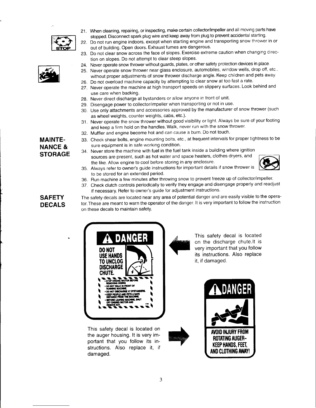
This safety decal
is located on
the auger housing.
lt is very im-
portant
that
you
follow its
in-
structions.
Also replace it, if
damaged.
21.
When cleaning,
repairing,
or
inspecting,
make certain
collector/impeller
and all
moving
parts
have
stopped.
Disconnect
spark
plug
wire and
keep
away
from
plug
to
prevent
accidental
starting.
Do
not run
engine
indoors,
except
when starting
engine
and transporting
snow thrower in or
out
of building.
Open
doors.
Exhaust
fumes are dangerous.
Do not clear
snow
across
the face
of slopes.
Exercise
extreme
caution
when changing
direc-
tion on
slopes.
Do not attempt
to clear
steep
slopes
Never operate
snow
thrower
without
guards,
plates,
or other
safety
protectton
devices
in
place
Never operate
snow
thrower
near
glass
enclosure,
automobiles,
window
wells, drop
off, etc .
without
proper
ad.justments
of
snow
thrower
discharge
angle.
Keep
children and
pets
away
Do
not overload
machine capacity
by attempting
to clear
snow
at
too
fast a rate.
Never operate
the machine
at
high
transport
speeds
on slippery
surfaces.
Look behind and
use care
when backing.
28.
Never
direct
discharge
at
bystanders
or
allow
anyone
in front of unit.
29.
Disengage
power
to collector/impeller
when
transporting
or
not
in
use'
30. Use
only
attachments
and accessories
approved
by
the
manufacturer
of snow
thrower
(such
as
wheel
weights, counter
weights, cabs,
etc.).
31.
Never operate
the snow
thrower
without
good
visibility
or
light.
Always be
sure of
your
footing
and
keeo a
firm
hold on the
handles.
walk,
never
run
with the snow
thrower.
32.
Muffler and
engine
become
hot and
can
cause
a burn.
Do
not touch'
33.
Check
shear
bolts,
engine
mounting
bolts,
etc.,
at frequent
intervals
for
proper
tightness
to be
sure
equipment
is in safe
working condition.
34.
Never store
the
machine
with fuel
in the
luel
tank
inside a building
where
ignition
sources
are
present,
such
as
hot water
and
space
heaters,
clothes
dryers,
and
the
like. Allow
engine
to cool
before
storing
in any
enclosure.
35.
Always
refer to owner's
guide
instructions
for
important
details
if
snow
thrower is
to be stored
for an extended
period.
36.
Run machine
a
few
minutes after
throwing
snow
to
prevent
freeze up
of collector/impeller.
37. Check
clutch
controls
periodically
to
verify
they engage
and
disengage
properly
and
readjust
if necessary.
Refer
to owner's
guide for adjustment
instructions.
The safety
decals
are
located near any
area
of
potential
danger
and are
easily
visible
to the opera-
tor. These
are
meant to
warn the operator
of
the danger.
lt is
very important
to
follow the
instruction
on
these decals
to
maintain safety.
This
safety
decal
is
located
on
the discharge
chute.lt
is
very
imponant
that
you
follow
its
instructions.
Also
replace
it.
if
damaqed.
AI|()ID IIIJURY
FR(IM
ROTATIIIG
AUGER.
I(EEP HAI{I)S,
TEET,
AI{O CLOTHI]IG
ATYAY!
Page 5
ASSEMBLING
YOUB
UN|T
TOOLS
REQUIRED
CHUTE
ASSEMBLY
FUEL
&
OIL
MIXTURE
.
Socket wrench
set
.
A
pair
of
pliers
.
Screwdrivers
(Phillips
head)
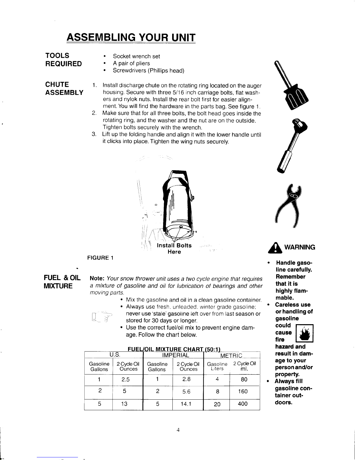
Install
discharge
chute on the rotating
ring located
on the auger
housing.
Secure with
three
5/16
inch
carriage
bolts, flat wash-
ers and nylok
nuts. Install
the rear
bolt
first
for
easier align-
ment.
You will find
the hardware
in the
parts
bag.
See
figure 1.
Make
sure that for
all three
bolts, the bolt head
goes
inside
the
rotating
ring,
and the washer
and
the nut
are on the
outside.
Tighten
bolts
securely with
the wrench.
Lift
up the folding
handle
and
align
it
with the lower handle
until
it
clicks into
place.
Tighten
the wing
nuts
securely.
Install
Bolts
Here
:
'
FIGURE 1
Note:
Your
snow thrower
unit uses a two
cycle engine that
requires
a mixture
of
gasoline
and oil for lubrication
of bearings and other
moving
parls.
.
Mix the
gasoline
and oil in a clean
gasoline
container.
.
Always
use
fresh.
unleaded.
winter
grade gasoline
I
a.,
never
use'stale'gasolne
lett over f rom last
season or
teL
tr
stored for
30 days
or
longer.
.
Use
the
correct fuel/oil mix
to
prevent
engine dam-
age. Follow
the chart
below.
2.
J.
\
r
I
't.
I
wnnNtNG
Handle
gaso-
line
carefully.
Remember
that it is
highly flam-
mable.
Careless
use
or
handling
of
gasoline
could
r--t
ff:*u
hazard
and
result in damage
to
your
person
and/or
property.
Always
fill
gasoline
con-
tainer
out-
doors.
i
I
L
S.
IMPERIAL
ME
Gasoline
Gallons
2 Cvcle
Oil
Ounces
Gasoline
Gallons
2
Cvcle Oil
Ounces
Gasoline
2 Cyde Oil
Liters
ml.
'l
2.5
1
2.8
A
BO
z
z
5.6 B
160
6
1?
5 14.1
20
400
Page 6
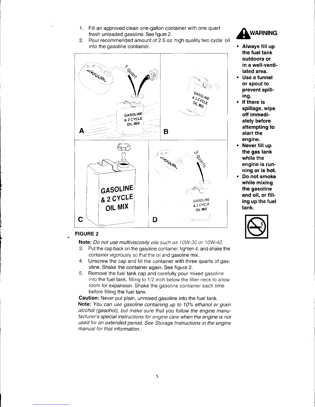
1.
Fill
an approved clean one-gallon container
with one
quart
fresh
unleaded
gasoline.
See
figure 2.
2. Pour recommended
amount ol
2.5
oz.
high
quality
two cycle
into the
gasoline
container.
oil
WARNING
Always fill
up
the fueltank
outdoors
or
in
a well-venti-
lated
area.
Use a funnel
or spout to
prevent
spilling.
lf there is
spillage, wipe
off
immediately before
attempting
to
start the
engine.
Never fill up
the
gas
tank
while the
engine is running
or is hot.
Do not
smoke
while mixing
the
gasoline
and oil,
or filling up the fuel
tank.
\,
o?fgj'u
ou
iif,
-Y--i..,
1
d
Yz
t
-\:i
GAsoLINE
I
&2
cYcLE',)
2\tt
vl--,
olL
Mlx
I
GASOLINE
&
2
CYCLE
olL
Mlx
FIGURE
2
Note:
Do not
use multiviscosity
oils such as
10W-30 or 10W-40.
3.
Put
the
cap back on the
gasoline
container,
tighten it,
and shake
the
container vigorously
so that
the oil and
gasoline
mix.
4.
Unscrew
the cap
and
fill
the container with three
quarts
of
gas-
oline.
Shake the container
again. See
figure 2.
5. Remove
the fuel tank
cap
and carefully
pour
mixed
gasoline
into
the fuel
tank, filling to 112 inch
below the filler neck to allow
room for
expansion.
Shake the
gasoline
container each time
before filling
the
fuel tank.
Caution: Never
put plain,
unmixed
gasoline
into the fuel tank.
Note: You
can use
gasoline
containing up to
10%
ethanol or
grain
alcohol
(gasohol),
but make
sure
that
you
follow the engine manu-
facturer's
special instructions
for
engine
care
when
the engine is not
used
for
an
extended
period.
See Storage lnstructions in the
engine
manual
for that
information.
Page 7

N
CONTROLS
Note:
/t is
very important
to know
and understand the
controls
and
.A,
safety
devices
of
your
snow thrower
before
you
attempt
to operate
AWARNING
THROTTLE
IGNITION
SWITCH
CHOKE
CONTROL
PRIMER
BUTTON
ELECTRIC
STARTER
AUGER
CLUTCH
CONTROL
DISCHARGE
CHUTE
CONTROL
SNOW
DISCHARGE
DEFLECTOR
This
deflector is
used to
control the
distance that
the
snow
will
be thrown.
t--l
it.
Make
sure that
the operator
of the
snow thrower has
read
:
lts |
this manual
and understood
the
Safety Operation Rutes
on
'
The
operation
pages
2
& 3 before running
the unit for
the first time.
Refer
of
any
snow
to the
manual
again for
ctarification whenever
any
question
arises.
thrower
can
result
in for-
The
snow thrower
does not have
a
remote throttte
for
controlling the
:'-T-obi"g-
:
3:
::l I I
3
:
3
::: :::T;ff
i:i ll:."*',:".'"W
l"mml;i
"'"'l
n
"-
llijfu
tr
This
switch
is
used to start
and
stop the engine. Insert
key in the
eyes
resulting
switch
and turn
switch to
ON
position
to start the
engine;turn
switch
in
severe
eye
to
OFF
position
to
stop the
engine.
damage.
Pro-
tect
your
eyes
This
control
is
used to
enrich the fuel
mixture
to start a cold
engine. with
safety
A warm
engine will
normally
not require
choking to
start.
You
can
glasces
or eye
locate
the
operating
position
for
the choke control on the
decal.You shie|ds
when-
may
have
to
partially
close
the
choke to allow the cold
engine to run ever
you
oper-
smoothly
until it warms
up.
ate
this
unit.
.
This
machine
This
button helps
in
starting
a cold engine
Depress
the
primer
but-
can
be danger-
ton to
supply
extra
fuel
mixture
to
start
the
cold engrne. Do
not
ous if used
prime
a warm
engine
since it will flood
the
engine.
carelessly.
So
On electric
start models,
plug
the
cord for the
electric
starter swrtch
be ca.reful
in
into
the receptacle
on
the unit. Next,
plug
the
other end into
a t20V
handling
it'
AC household
receptacle.
Next
depress the
starter
button to start
'
Never ignore
the motor
and
crank the
engrne.
safety
devices
Note: You
can start these
electric
start engines manuatty with
the
ortYTass
starter rope.
See
instructions
on how
to use electric
starter.
.
Never
operate
This
control
starts and
stops the
auger. Pull the
control back against
ll"
the handle
to
start the
auger; release
the
control to stop the auger.
thrower
with-
When the
auger
touches
the
ground
the
snow thrower moves for-
out
all
guards,
ward. Do not
manually
turn
the
auger
in
a clockwise
direction
covers,
and
because that
will loosen
the
belt
and unthread the
pulley
shields in
place.
This
control is
used to rotate
the
discharge
chute to the desired
direction. Turn
crank
clock-
wise
to rotate
the chute to
\ \ \N- -.1/ l.r Snn*
\l \r -/t/\
Snow
-r=i4
-_/.
_'-.-
Dischar.
!ru /
**
*Derrectr
rl
\\\\
|
\\
t =
Spark
rition
--
,6i
Plug
the right, turn
it counter-
.
,1q
-.<.
r--ts
Discharge
clockwise to rotate
the
Ayg"! 7b
,
vYw
*
Derlector
chute to the left.
""#f:i
\\
|
,
=)
lgnition
\,
\
Switch -',
Move deftector
up to throw
e'i;1;"tffi.Discharge
.
^h^,^, +, ,r+hav. ma,,a ^^{r^^
'
'
t
/'-
I
-{
\l
Chute Control
snow
further;
move
flgflon-
Choke
tor down to
throw snow
c'J},i',Jr E\11
--f_l!!r$
tFql'l:
FIGURE
3
6
ctoser.
Starter
Page 8

opennnruc rne
urur
Note:
The
snow
thrower
engine is
designed to operate
at cold tempera-
tures and will
be difficult
to
start in warm weather.
Avoid
operating
your
snow thrower in warmer
conditions
since
engine
may
vapor lock
and stop
running
after a short time.
Never
run the
engine
indoors
or in enclosed,
poorly
ventilated
areas.
Engine
exhaust
contains
CARBON
MONOXIDE,
an
ODORLESS,
DEADLY
gas.
Pull
Start Models:
See figure
4.
1. Insert
key
in ignition
switch and
turn key to
ON
position.
2. Move
choke control lever
to the
ON
position
on cold engines. lf the
engine
is warm
from
operation,
this
step
may
not
be
necessary.
3.
Push
the
primer
button two
or three times holding
finger
over
vent
hole. Allow
a
few
seconds between
each
push
for
air
to
enter bulb
through
vent hole.
You may have
to
prime
more for
the
initial
start at
temperature
below 150F/-1OoC.
4.
Grasp the starter rope
handle
and
slowly
pull
out the rope
until
you
feel a resistance.
Allow
the
rope to rewind
slowly,
then
pul
it
out rapidly
to start
the
engine.
Let the rope return
slowly to
the
starter. lf the
engine
does not
start after three
pulls, push
primer
button one
more
time
and
pull
the
starter rope.
FIGURE
4
----'
5.
Once
the
engine
starts
and
gradually
warms
up, move the
choke
lever
to the
OFF
position.
Be
prepared
to
move the
choke
lever
to
the
ON
position
if
the
engine
sputters
during
warm
up.
6. Allow
the
engine
to
warm
up before
snow throwing.
The
engine
will
operate
at full
throttle when
it warms
uo.
Electric
Start
Model:
See figure
5.
Note:
Ihe
electric
starter is
designed
to
operate on 120
votts AC
household
power
supply
using
the
power
cord supptied with
your
snow thrower.
When
using the
power
cord, match
the wide
btade
of
the
plug
to the
wide
slot of
the receptacle.
7. Follow
steps 1-3
from
"pull
start model"
section.
B.
Plug
power
cord into
receptacle
on the starter
switch first,
then
plug
the
other
end
of the
cord into
a
standardl20 volts
AC
household
outlet.
Do
not
use
any extension
cord to lengthen
the
power
cord
supplied
with the
unit.
WARNING
STARTING
ENGINE
.
Wear
safety
glasses
while
operating
the
unit.
.
Never
direct
discharge
at
bystanders
or
allow anyone
in
front
of the
unit.
.
Never
direct
discharge
towards
win-
dows.
.
Neveroperate
the
unit
without allguards,
clvens, and
shields
in
place.
.
Stop the
engine
whenever leaving
the operating
position.
.
Stop the
engine,
remove the
key, and
dis-
connect
the
spark
plug
before unclogging
auger
housing
or
discharge
chute and/or
before
mak-
ing
repairs
or
adjustments.
.
To
reduce
the
risk
of fire,
keep
the unit
clean
and
free
from
spilled
gas,
oil;
and
other
I
debris.
Page 9

a Make sure
that there
is no moisture
on the cord
ends
or
.r.
A
receptacles
when
plugging
in the
cord.
AWARNING
9.
Push the starter
button
to
crank
the engine.
Do
not crank
the
engine
for more
than 15 seconds
without allowing
the
electric
'
Do not use
starter
to cool
for around
10 minutes.
Attempt
further cranking
snow tltrower
only atter
the starter
has
cooled
down.
on surfaces
4\
Do not
push
the
primer
button
while
the engine
is
above
ground
A
o"i"g
"I""k"d.
level'
such
as
Electric start engines
can be
severely
damaged
if
you
the roof of a
do not follow
proper
starting
instructions.
building'
Release
starter
button
once
the engine starts
and
gradually
move the choke
lever to the
OFF
position.
Disconnect
the
power
cord
from
(i)
household
receptacle
and
then from
(ii)
starter
switch
on the snow
thrower.
Store
the
cord
in
a dry
place.
10
rnE-
--
S[ey
away
frorn the
front
of
your
snow
t|trcrer
unit
whcn the
augGf
is turnIng.
Avoid
plcking
up
gravel
wfth the
augor
since
this could
damage
the
unit and/or
cause
serious
injury
to the
operator.
Always
be
alert to
the
hidden
hazardsthatmight
be struck
by
the
auger.
Should
you
hit a
foreign
object
with
the
auger
stop
the
engine
imme-
dlately,
remove
key,
dlsconnect
sparkplugand
inspect
the
machlne
for
any
damage.
Repair
dam-
age
before
operating
the
unit
again,
11.
.--,/Y
;'-
Starter---=--.
itrS.Button\g
-,
!v/
(9
STOPPING
ENGINE
THROWING
SNOW
.1.
2.
.A.
Always disconnect
power
r Ievn
A
cord
from the
household receptacle
first, then
unplug
t.1
';i
r-=\
\.{ir
\
\./
\
/,/
{==/'
from
starter
switch.
Turn
ignition key to the OFF
position.
Remove the
key from the switch
if
you
are
leaving the
operating
position
and/or
before
making repairs
or adjustments.
Allow the
unit
to
run for a few
minutes before
storing.
Note:
Ihe snow
thrower will be
pulled
forward by
the auger as
the
handle
is raised.
The
unit
will also
move
forward
when the auger
comes
in contact
with the accumulated
snow.
1. Before entering
the area
where snow
needs
to be cleared,
,adjust
the
position
of the discharge
chute
so
that snow
will be
thrown
in
the
desired direction.
Note: Snovv should
not
be
thrown towards
buildings,
automobiles,
or
people.
Always try to throw
snow down
wind.
2. Adjust the deflector
on
top
of
the discharge
chute
up or
down
to
control
the distance
that the snow
will
be
thrown. See
figure
6.
n
Disengage
auger drive before
A
adiusting
discharge
deflector.
3.
Review the area
to be cleared
of
snow
and establish
a
pattern
for
the
most efficient
snow
removal.
4.
Inspect the area
for
possible
obstructions
like
gravel
and
rocks.
Remove,
if
any.
5.
Begin snow
removal
by clearing
a
path
down
the center
of a
walk or
driveway along
your
pattern
for snow
removal. Gradually
widen
the
path
throwing
snow
to both sides.
Allow
the
snow
thrower
to
move
the snow at
its own
pace.
6.
When clearing
wet and
heavy snow,
you
may
have
to
push
down
the
handle and dow
down.
But allow
engine
to work
at
f ull
throttle'
Lower
The
Chute
For
Shorter
Distance
FIGURE
6
FIGURE 5
Page 10

ADJUSTMENTS
To avoid serious
bodily injury on
the
job
when
performing
adiustments,
maintenance or
lubrication,
stop
the engine,
remove
key from the switch
and disconnect the spark
plug.
Follow safety
instructions
mentioned
here
and safety
labels on the unit.
REMOVING
ENGINE
COVER /COWLING:
ln many of the adjustment and
service tasks,
you
will
have to
first remove the en-
gine
cover/cowling,
perlorm
the task, and
reinstallthe cover.
A. Remove key from the ignition switch.
B. Remove the three screws
holding the discharge
chute
to the rotating
ring.
Remove the chute.
See
figure 7.
C.
Remove the two hex bolts
from
the
top of the engine
cover.
D. Remove two screws
and
flat washers
each
from
inside the auger
housing,
rear of the cover, and both sides of
the cover.
E. Remove the
fuel
tank cao and
lift the
cover and
cowling carefuily up and
away
from the engine exhaust
pipes.
Reinstall
the
cap on
the fuel tank. Do
not lose
the hardware.
During
reassembly of cover and cowl-
ing, remove
fuel tank
cap
first. Next,
make sure
that the metal
grommet
for
engine starter
rope is in
position
between cowlings.
The
tabs at
lower
front
of cover must be
positioned
to
the inside
of belt cover on
the left and
inside
the lower
cowling on
the right.
Leave retaining
screws loose until all
are
in
place,
then tighten them
securely. Reinstall fuel tank
cap.
La.
FIGURE
7
AUGER
Note:
Ihe length
of the auger ctutch cable
is adjustable,
However,
you
wilt not have to do
CLUTCH
this frequently
since the operating tension
on the drive belt
is maintained by the clutch
CABLE
engaging
spring on
the
end of
the
cable.
.
lf the auger turns slowly
under
heavy
load
or
you
hear the drive belt
squeal
,
when
entering
heavy
snow, reduce
the length of
the
cable.
This will increase
the
pressure
applied
by the idler
pulley
on the drive
belt.
.
lf
auger
continues
to turn
after
the clutch control
is released, the cable is too
tight. Increase
the
length
of
the cable so that
the
cable
is
slightly slack
when
clutch
control
is released.
1.
Access
the
clutch cable adjusting
nuts
by
removing the engine cover and cowling.
2.
Measure the
spring while the
clutch
control on
the handle is in the disengaged
posi-
tion. Record
this measurement.
3.
Pull
the
clutch control
against the
handle
and
again measure the spring.
Record
this
measurement.
4.
Compare the
two measurements - the figure obtained with the spring extended
should be 7/16th inch
greater
than with
the
spring unextended.
lf it is not,
you
will
need
to
alter
the lenqth
of the
cable.
I
1l
I
I
I
i
I
I
I
I
l'
Page 11

6.
5. To reduce
or extend the lengrth
of the
clutch
cable,
adjust
the
nuts
on the clutch
cable.
See
figure
8. Reducing
the
cable
lengh
will increase
idler
pulley pressure
on
the belt.
Use extreme
caution when
mak-
ing
adjustments
that require
engine to
be running.
i,..:
_.
Keep
hands, feet,
hair
and loose
clothing
away from
any moving
parts.
Start
the
engine
and
pull
back on
clutch
control to
operate the
auger.
Release
the
clutch
control and
check to
be sure that
the auger
stops turning.
FIGURE
Cable must have
some slack when
the
clutch
control is released.
lf the
auger
continues to
turn after the
clutch
control is released,
the
cable is too tight.
Adlust the nuts acccrdrngly.
8.
Reinstall
the
engine
cover/cowling
and
secure
with
the
correct ha.dware.
.
The
carburetor
is
properly
calibrated
and
pre-set
at
the factory
for
eff
icrent
cold
weather
operation. There
are no
adjusting
screws on the
carburetor
.
lf
you
feel,
during operation
of the snow
thrower,
that
the
carburetor
is not
providing
adequate fuel
supply
to
the engrne,
contact
your
nearest
Authorized
Tecumseh
Ser-
vice
Outlet
for
service.
CARBURE.
TOR
I
*l
-,
.
I
\
j'
I
b*"-
Page 12

MAINTENANCE
To
prevent
accidental
starting
of
engine
during
maintenance
or service,
always
remove
ignition
key
from switch.
Apply a few drops
of light
machine oil
to the upper
end
of the
clutch control
cable.
Wipe off any excess
oil.
This
will ensure
free
movement of cable
through
outside casing.
See
figure 9A.
The drive
pulley
end of auger shaft
is supported
by a
sealed
ball
bearing
and
requires no lubrication.
The ball
bearing
on
the other
end of
the
auger
shaft
is also sealed
and
will
not
reouire
lubrication.
At the beginning
of each snow
throwing season,
remove dis-
cl'rarge
chute and
generously
lubricate the steel
flange
at the
back
of
the rotating
ring with light
grease
such
as
Lubriplate.
Rotate the
ring with crank to distribute
the
grease.
See
figure 98.
Remove
the belt cover and
lightly apply
oil to the
pivot point
for the idler
pulley
arm.
MAKE
SURE
THATYOU
DO
NOT
SPILL OIL ON
THE BELT
OR
THE
PULLEYS. See
figure 9C.
The
two-cycle engine used
on this snowthrower
is
lubricated
by
the
gasoline/oil
mixture. Observe
recommended
gasoline
to
oil
mixture
ratio
shown on
pages
4 & 5.
The
drive belt
idler
pulley
has
a sealed
bearing
that
requires
no lubrication.
Remove key from the ignition switch
and disconnect
spark
plug.
Remove the belt cover.
Remove
the engine cover/cowling
following
instructions on
page
9.
Move the
auger control bail
on
the han-
dle and slio the belt out
from
between
the brake lever
and
the
roller
and away
from
the idler
pulley.
See
figure 10.
Remove
the belt from the engine and
1
auger
pulleys.
Install
the new belt
around
the engine
and auger
pulleys
and underneath
idler
pulley.
THE
RIBBED
SIDE OF
THE
PULLEY MUST
BE INSIDE, AGAINST
THE AUGER AND
ENGINE PULLEYS.
Slip belt into
place
between the brake
lever
and the roller.
LUBRICATE
FIGURE 9A
-
\:,
.,,'
n'6t
-
, I
\(-)
FIGURE 98
FIGURE 9C
Removing
Belt Cover
ln
many of
the maintenance
tasks,
you
will
have to
first remove
the
belt cover,
perform
the
task, and
reinstallthe
cover.
A. Remove
key
from the
ignition switch.
B.
Remove
the four screws
from
the side cover.
C.
Remove
the cover.
D. Lubricate
the
pivot point
and
reinstall
the cover
in
reverse order
LUBRICA.
TION
REPLACING
DRIVE
BELT
'1.
2.
4.
5.
6.
1.
2.
?
4.
q
o.
7.
1l
FIGURE
1O
Page 13

8.
q
4.
start
engine; engage
and
disengage auger
clutch control
to be sure that
the
auger
stops turning
when the
clutch control is released.
lf the
auger
does not
stop turning
when control is
released,
adjust the tension
on the
clutch control
cable following
instructions
on
page
6.
Reinstall
the
belt cover
and the
enoine cover/cowlino.
10.
REPLACING
1.
SHAVE
2.
PLATE
SERVICING
1,
SPARK
2.
PLUG
^
Remove
key from
ignition
switch.
Remove
the three
screws and nuts
securing
the
shave
plate
to the
auger housing.
Save the hardware.
See
figure
1 1.
Remove
the worn
blade.
Installthe
new
blade
and
secure
it
with the
three
screws
and nuts
ear-
lier removed.
Remove
key
from the
ignition
switch.
Remove
the
engine
cover following
instructions
on
page
1 1.
Disconnect
wire from
the
spark
plug
and remove
the
plug.
See figure
12A.
Inspect
the
plug
and
clean
carbon
deposit
from the
electrodes
with
a
wire
brush.
lf the
plug
is
burned or
pitted.
replace
it
with a new
plug (part
# 731-0732)
as
recommended
in
the
engine
manual.
Adjust
the
gap
between
electrodes to
.030
inch
using a wire feeler
gauge.
See
figure
128.
Install
the
plug
and tighten it firmly.
Reconnect
the
plug
wire.
8.
Reinstall
the
engine
cover/cowling.
FIGURE 12A
Electrodes
.030 Gap
FIGURE
128
FIGURE 11
4.
tr
Shave
Plate
Bolts
t2
Page 14

STORAGE
DRAIN CAR.
BURETOR
Carburetor\
'
Never
store
unit
with fuel
in
tank
in
poorly
venti-
lated enclo-
sures,
where
fuelfumes
may reach an
open flame,
spark
or
pilot
light as on
fur-
nace,
water
heater,clothes
dryer,
etc.
.
Gasoline
is
highly
flamma-
ble and cars
F,*f6l
fiun
lEvl
in serious
fire
hazard
result-
ing in damage
to
person
and/
or
property.
.
Drain
fuel into
approved container outdoors andaway
from arry open
flame.
.
Makesurethat
the engine is
cool
to the
touch before
you
start
draining the
fuel.
',:G
\FsTlP--2
/'ffi
DRAIN FUEL
1.
CLEAN U}IIT
1
2.
LUBRICATE
1
Z.
STOP
COR.
ROSION
SERVICE
PARTS
STORE UNIT
3.
Handle
gasoline
carefully.
Drain fuel in approved container
outdoors
and
away
from open
flame.
Do not smoke.
Remove all
fuel from
carburetor
and
fuel tank
to
prevent gum
deoosits.
Drain
fuel into approved container
outdoors
and away
from
any
open
flame. Make sure that the engine
is cool to
the touch.
Do
not
smoke.
Dispose off the
fuel in an
EPA-approved
place.
Run
engine until
the fuel tank
is
empty
and
the engine
stops
due to lack of fuel.
lf
you
had used
gasohol,
follow the
above
steps.
then
put
1/2
ptnt
of fuel-oil mix
(mixed
arcording
to chart on
page
4)
and
run engine
till
fuel tank is dry For
more
details. consult
engine
manual.
Clean
your
snow thrower unit thoroughly.
Wipe
all surfaces
with a rag.
Lubricate wheel hubs.
auger clutch
control bar
with oil.
Lubricate discharge chute
flange. Follow
instructions on
page
8.
Pull
starter handle slowly until
you
feel a resistance
from com-
pression
pressure.
Stop
pulling
the handle. Release
the
starter
tension slowly
to
prevent
engine
from reversing from compression
pressure.
This
position
will
close
the intake and exhaust
ports
and
pre-
vent
corrosion
of
the
piston
and
the cylinder bore.
Inspect
unit
for
damaged or missing
parts
and replace
these as
needed.
Follow
the illustrated
parts
list to order
parts.
Store the
snow
thrower unit indoors,
if
possible,
and cover to
keeo
off dust
and dirt.
1.
3.
1.
Note: /f the unit
is to be
left
unused
for
30
days
or more,
or
if
the unit
a
is to be stored
for the
it atitii,
ir"p,^r"
inl" snow
thrower
fotnwing
A
WARNING
these
instructions
for storaee
1. Locate the bowl
drain below
the
carburetor.
See
f igure 14.
2. Press upward on
bowl drain
and
drain
the carbure-
tor.
(This
is
appli-
cable only
when
your
unit
is
so
equipped.)
Bowl Drain
FIGURE
14
IJ
Page 15

BLESHOOTING
PROBLEM
POSSIBLE
CAUSE REMEDY
Engine
does not
start
1. Key
not in
ON
position
2.
Choke in
OFF
position
3.
Fuel
tank empty
4.
Old
"stale"
fuel
mixture
5. Faulty
spark
plug
6. Engine not
primed
Turn key to
ON
position
Move choke
to ON
position.
Fill fuel tank with
fuel-oil
mix.
Drain the
stale fuel
mixture;
refill
with fresh fuel
mixture.
Replace
spark
plug.
See
page
12.
Push
primer
button two
or three
times following
starting
instructions.
Engine runs
erratic,
sputters
12Incorrect
spark
plug
gap
Choke in
ON
position
after
engine
has
warmed
up
Fuel
contaminated
with
water
and/or
dirt
particles
Gas cap vent hole
plugged
Adjust
gap
to .030".
Move
choke to
OFF
position.
Drain and refillwith fresh
fuel
mixture
Clean
vent
hole
or
replace
cap.
Unit does not
throw snow
'1.
Loose
or broken
drive belt
2. Incorrect
control cable
adjustment
3.
Discharge
chute clogged;
foreign
object lodged in
auger
4.
Carburetor
not supplying
enouoh fuel
Adjust or replace
belt
See
page
1 1.
Adjust
cable length.
See
pages
g
and 10
Stop engine, remove key
and
clean
the
discharge
chute.
Contact
the nearest
Tecumseh
service outlet
Auger
does not stop
turning
when
control is released
1.
lncorrect
adjustment
of
control
cable
Adlust
cable length. See
pages
9
and 10.
Unit vibrates
excessively
1.
Loose
parts
2. Damaged
auger
Stop engine, remove key
and check.
Make necessary repairs;
tighten
bolts.
Take
snow
thrower
to an
authorized
service dealer.
Unit
loses
power
1.
Spark
plug
wire loose
2.
Gas
cap
vent hole
plugged
3. Exhaust
port plugged.
Connect
and tighten spark
plug
wire.
Bemove
ice
and snow from
cap, and
make
sure that the
vent
opening is
clear.
Clean the exhaust
port;
see engine
manual for instructions.
Follow step-by-step
instructions
and observe safety rules to make
adjustments and
repairs
on
your
snow thrower.
For repairs
and adjustments
beyond those
listed above,
please
contact the tactory
or authorized service dealer
near
you.
\
t4
Page 16

HEX CAPSCREW
CARRIAGE
BOLT
PLAIN
WASHER
LOCK WASHER
HEX
CAPSCREW
IDENTIFICATION
Shown
below
are actual
size
hex heads for
standard
screw
sizes.
Example:
a114" screw
has a 7/16 head and thus
requires
a7116 wrench.
To measure
length, use the scale below.
STANDARD
FASTENER
3/4"
Head
screw with
1/2"
S.D.
5/8" Head
screw
with
7/16" S.D.
I
Screw
Shaft
/
Diameler
J
112x2
\crew
Length
SAMPLE:
NUT IDENTIFICATION
lnside
Diameter
l5
IDENTIFICATION
CHART
Hardware
sizes are
given
throughout
this
manual.
lf a
washer or nut
is identified
as
"washer,
112" or
"nul,112",
this
means the
inside
diameter
is 1/2 inch.
lf
a screw
is identified as
"screw.
112 x 2", this
means
the shaft
diameter
is 1/2 inch
and
the shaft of
the
screw
is
2
inches long. lf a screw
is
identified as
"screw,
112-16 x
2", the
number
"16"
means
that
the screw
has 16
threads
per
inch.
SAMPLE:
SCREW
IDENTIFICATION
Shaft
Diameter
Ooooo
9/16"
Head
112"
Head
7/16" Head
screw
with
screw
with
screw
with
3/8" S.D.
5/16' S.D.
1/4"
S.D.
S.D. = Shaft
Diameter
WASHER
AND
NUT IDENTIFICATION
Place
the washer
or nut
on the
above scale to
determine the
in-
side diameter.
The
actual
inside
diameter
can
vary 1116 inch.
Use the scale
for
comparison.
0
3
4
t
i2
1/2
t/2
1/2
3/4
3/4
1.4
1/4
3/4
3/4
1/4
1/4
Nut,
'U2
Page 17

TORQUE
SPECIFICATIONS
FOR
STANDARD
MACHINE
HARDWARE
TOLERANCE!2Oo/"
srzE
SAE
GRADE
#2
.o
SAE
GRADE
#5
a
SAE
GRADE
#8
e9
In./Lbs.
Ft./Lbs.
Nm.
ln./Lbs.
Ft./Lbs.
Nm.
ln./Lbs.
Ft./Lbs.
Nm.
8-32
8-36
10-24
10-32
1t4-20
1t4-28
5/1
6-1
8
5116-24
3/8-16
318-24
7116-14
7/16-20
112-13
1t2-20
9t16-12
9/1
6-1 8
5/8-11
5/8-18
314-10
314-16
718-9
718-14
1-B
1-12
19
2.1
20
2.3
27
3.1
31
3.5
66
7.6
76
8.6
11
15.
12
16.3
20
27.2
23
31.3
30
40.8
35
47.6
50
68.
55
74.8
65
88.4
75
102.
90
122.4
100
136.
160
217.6
180
244.8
140
190.4
155
210.8
220
299.2
240
326.4
30
3.4
31
3.5
43
4.9
49
5.5
--6-
1d3-
10
13.6
17
23.1
19
25.8
30
40.8
35
47.6
s0
68.
55
74.8
75
102.
90
122.4
1 10
149.6
120
163.2
150
204.
180
244.8
260
353.6
300
408.
400
544.
440
598.4
580
788.8
640
870.4
41
4.6
43
4.9
60
6.8
68
7.7
-T
16.3
14
19.
25
34.
25 34.
45 61.2
50
68.
70
95.2
80
108.8
1
10
149.6
120
163.2
150
204.
170
231.2
220
299.2
240
326.4
386
525.
420
571.2
600
816.
660
897.6
900
1,224.
1,000
1,360.
NOTE:
1. These
torque
values
are
to be
used
for all
hardware
ex-
cluding:
lock
nuts, selt-tapping
screws,
thread
forming
screws,
sheet
metal
screws
and
socket
head
setscrews'
2. Recommended
seating
torque
values
for
lock
nuts:
a.
For
prevailing
torque
lock
nuts-use
65%
of
grade
5
torques.
b.
Forflange
whizlock
nuts
(and screws)-use
135"/"
ot
grade 5 torques.
3.
Unless
otherwise
noted
on
assembly
drawings
all
torque
values
must
meet
this specification.
BOLT
HEAD
MARKING
S.A.E.
GRADE:
o
e
€
t6
Page 18

A$Cadet,
LIMITED
WARRANTY
TWO.YEAR
RESIDENTIAL
ONE.YEAR
COMMERCIAL
Proper
maintenance
of
your
Cub
Cadet equipment
is
the owner's
responsibility.
Follow the
instructions
in
your
owner's
manual
for
correct
lubricants and
maintenance
schedule.
Your Cub
Cadet
dealer
carries
a complete
line of
quality
lubricants
and
filters
for
your
equipment's
engine,
transmission,
chassis
and attachments.
RIDING
MOWERS,
LAWN TRACTORS,
GARDEN
TRACTORS,
CUB
CADET
ATTACHMENTS
AND HOME
MAINTENANCE
PRODUCTS
This limited warranty
for
residential users,
covers any
defect
in materials
or
workmanship
in
your
Cub
Cadet
equipment
for two
years
lrom the date
o{
purchase for
the
first user
purchaser.
We will replace or
repa r any
part
or
parts
without
charge
through
your
authorized
Cub
Cadet dealer.
Batteries
have a one-year
prorated
limited warranty
with
100q6 replacement
during the
first three
months.
V-belts
for
either
the traction
drive or
any attachments are covered
for one
year
only.
Cub Cadet
equipment used
commercially
is warranted
for one
year
only.
(Commercial
use
is
defined
as either
having
hired operators or
used
for income
producing
purpose.)
ITEMS NOT COVERED
The warranty
does
not
cover
routine maintenance
items such as
lubricants,
filters
(oil,
fuel,
air
and hydraulic), cleaning, tune-ups, brake
and/or
clutch
inspection,
adiustments
made as
part
of
normal maintenance,
blade sharpening,
set-up,
abuse,
accidents
and
normal
wear. lt does
not
cover
incidental
costs such as transporting
your
equipment
to and
from
the dealer,
telephone
charges
or
renting
a
product
temporarily to
replace a
warranted
product.
There is nb
other express warranty.
HOWTO OBTAIN
SERVICE
Contact
your
authorized
Cub
Cadet servicing dealer
who
sold
you
your
Cub Cadet
equipment.
lf this
dealer
is not
available, see the
Consumer
Yellow Paqes under
"lawn
mowers"
for the
name
of a
dealer
near
you.
lf
you
need further assistance in finding an authorized Cub Cadet
servicing
dealer, contact:
Cub Cadet Corporation
Post
Office Box
368023
Cleveland,
Ohio
441
36-97
23
HOW
DOES STATE
LAW APPLY?
This limited warranty
gives
you
specific
legal rights, and
you
may also have other
rights which
vary
from state to state.
t1
Page 19

Ignition
KeY
Part
No.
125-0201
A
S
S
o
.R
T
E
D
P
A
R
T
S
L
I
Engine
Oil
(2
CYcle)
DENI-731't1227
Luger
Belt
oEM-754'0452
Spark
Plug
Part
No.
RCJ-8Y
Auger
Rubber
RePlacement
Kit
pait
No.753-
0669
Electric
Start
Kit
oEM-390'996-000
Shave
Plate
oEM-731'1728
Page 20

A$edPt
I
t
I
)
FORM
NO.770-0356M
PRINTED IN
U.S.A
 Loading...