

Page 1
310-3000
Integrated Hydrostatic Transaxle
Service and Repair Manual
BLN-51259
Revision Dec. 2008
Page 2

Table of Contents
Section
Page
Foreword........................................................................................................................ i
Description and Operation........................................................................................... ii
Introduction.................................................................................................................. 1
General Description.................................................................................................................... 1
Introduction................................................................................................................................. 1
Hydraulic Schematic.................................................................................................................... 2
Technical Specifi cations............................................................................................................ 3
Product Identifi cation.................................................................................................................. 3
Safety............................................................................................................................. 4
Personal Safety........................................................................................................................... 4
Tool Safety................................................................................................................................... 4
Work Area Safety......................................................................................................................... 4
Servicing Safety........................................................................................................................... 4
Troubleshooting............................................................................................................ 5
Service and Maintenance............................................................................................. 6
External Maintenance..................................................................................................... 6
Service and Maintenance Procedures............................................................................ 6
Fluids.............................................................................................................................. 7
Brake Maintenance......................................................................................................... 8
Return to Neutral Setting Hand Control.......................................................................... 9
Return to Neutral Setting Foot Control........................................................................... 10
Purging Procedures....................................................................................................... 11
Repair........................................................................................................................... 12
General Instructions...................................................................................................... 12
Required Tools.............................................................................................................. 12
Torque Specifi cations.................................................................................................... 12
Transaxle Removal....................................................................................................... 12
Limited Disassembly..................................................................................................... 12
How to Use This Manual............................................................................................... 13
Brake Assembly..........................................................................................................14,15
Bypass Assembly........................................................................................................... 16
Control Arm Assembly............................................................................................... 17,18
Torque Bracket Assembly.............................................................................................. 19
Fan and Pulley Assembly.............................................................................................. 20
Input Shaft Assembly.................................................................................................... 21
Charge Pump Assembly............................................................................................... 22
Lower Housing/Filter/Manifold Assembly...................................................................... 23
Planetary Differential Assembly............................................................................... 24,25
Motor/Center Section/Pump Assembly............................................................... 26,27,28
Directional Control Assembly........................................................................................ 29
Transaxle Installation.................................................................................................... 30
Assembly After a Complete Tear-down......................................................................... 30
Parts List................................................................................................................. 31,32
Glossary of Terms.................................................................................................. 33,34
310-3000 IHT
Page 3

FOREWORD
Headquartered in Sullivan, Illinois, Hydro-Gear® is
a world leader in the design, manufacture, and service of quality hydrostatic transaxles for the lawn
and garden industry. The mission of our company
is to be recognized by our customers and the industry as a world-class supplier and the quality
leader in everything we do.
This Service and Repair Manual is designed to
provide information useful in servicing the 3103000 Hydro-Gear Integrated Hydrostatic Transaxle
(IHT).
Also included is a glossary of terms that are
frequently used throughout the industry and in
Hydro-Gear service publications. Understanding
terminology is very important!!
It is necessary, and good shop practice, that your
service area be equipped with proper tools and the
mechanics to be supplied with the latest information available. All repair procedures
illustrated in this guide are suggested, but preferred methods of repair.
Repair procedures require that the transaxle unit
be removed from the vehicle.
Some cleaning solvents are fl ammable. To avoid
possible fi re, do not use cleaning solvents in an
area where a source of ignition may be present.
This is not a certifi cation, test or study guide for
a certifi cation test. If a technician is interested in
certifi cation they should contact an agent rep-
resenting the ESA (Engine Service Association)
(610) 363-3844 or their Hydro-Gear Distributor.
Many distributors will be hosting certifi cation test-
ing. These study guides will cover most of the
products and manufacturers in our industry.
For more information about Hydro-Gear or our
products, please contact your Central Service
Distributor, visit www.hydro-gear.com or call our
Technical Service Department at (217) 728-2581.
310-3000 IHT i
Page 4
SECTION 1. DESCRIPTION AND OPERATION
INTRODUCTION
The purpose of this manual is to provide useful information for servicing the Hydro-Gear
310-3000 Integrated Hy dro stat ic Transaxles
(IHT). This man u al includes transaxle general de scrip tion, hy drau lic sche mat ic, tech ni cal
spec i fi ca tions, product iden ti fi ca tion, safe ty,
trou ble shoot ing, main te nance, and re pair pro ce dures.
The transaxle normally will not require servicing during the life of the vehicle in which it is
in stalled. Should other ser vic ing be required,
the transaxle will need to be thoroughly cleaned
be fore be gin ning most procedures.
Please refer to the instructions titled “How to
Use This Man u al” in the Repair Section for an
ex pla na tion of the lay out of the disassembly,
in spec tion, and re as sem bly portions of this
manual.
®
GENERAL DESCRIPTION
The 310-3000 is a self con tained unit de signed
for the transfer and con trol of pow er. It provides
an in fi nite ly vari able speed range be tween zero
and maximum in both forward and re verse
modes of operation.
The transaxle uses a variable displacement
pump with a max i mum displacement of 10
cc per rev o lu tion, and motor with a fi xed dis-
place ment of 21cc per rev o lu tion. The vari able
dis place ment pump fea tures a cradle swashplate with a di rect-pro por tion al displacement
con trol. Re vers ing the di rec tion of the swash-
plate re vers es the fl ow of oil from the pump
and thus re vers es the di rec tion of the motor
output ro ta tion. The pump and motor are of the
axial piston de sign and utilize spherical nosed
pistons which are held against a thrust race by
internal com pres sion springs.
The 310-3000 has a self con tained fl u id sup ply
and an in ter nal fi l ter. The fl uid is drawn through
the in ter nal res er voir and feeds the fi xed dis-
place ment gerotor charge pump. Ex cess fl u id in
the charge circuit is dis charged over the charge
re lief valve and dumps back to case. Charge
check valves in the center section are used to
control the make up fl
pres sure side of the loop.
The transaxle is fi lled and tested at the factory
and should not re quire fl uid or fi lter changes
un less the fl uid be comes con tam i nat ed.
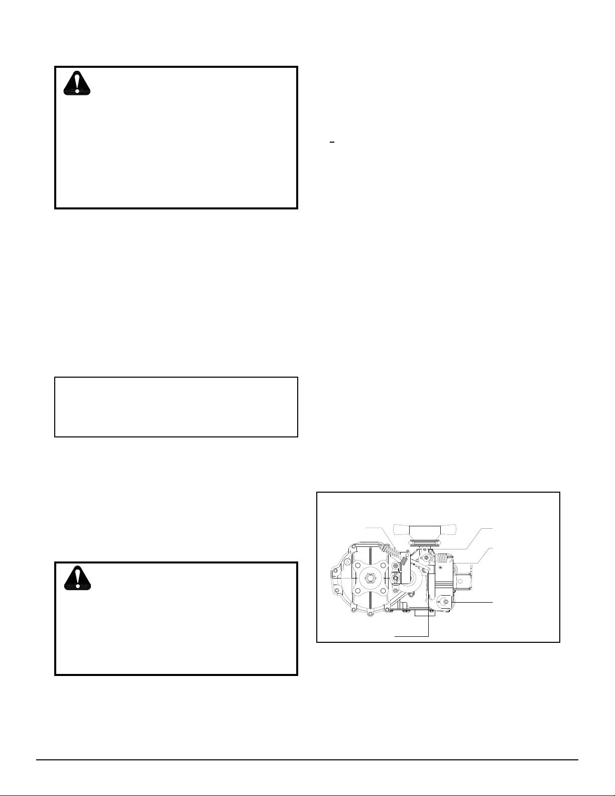
A cam style, block lifting bypass is utilized in
the 310-3000 to permit moving the vehicle for a
short dis tance at a maximum speed of 2 m.p.h.
(3.2 km/hr) with out start ing the engine.
ow of the fl uid to the low
WARNING
Actuating the bypass will result in the
loss of hy dro stat ic braking capacity. The
machine must be sta tion ary on a level
surface and in neutral when actuating
the bypass.
The 310-3000 utilizes an in-line fl oat ing disc
brake con trolled by a "cam" style ac tu at ing
arm.
ii
310-3000 IHT
Page 5
310-3000 IHT
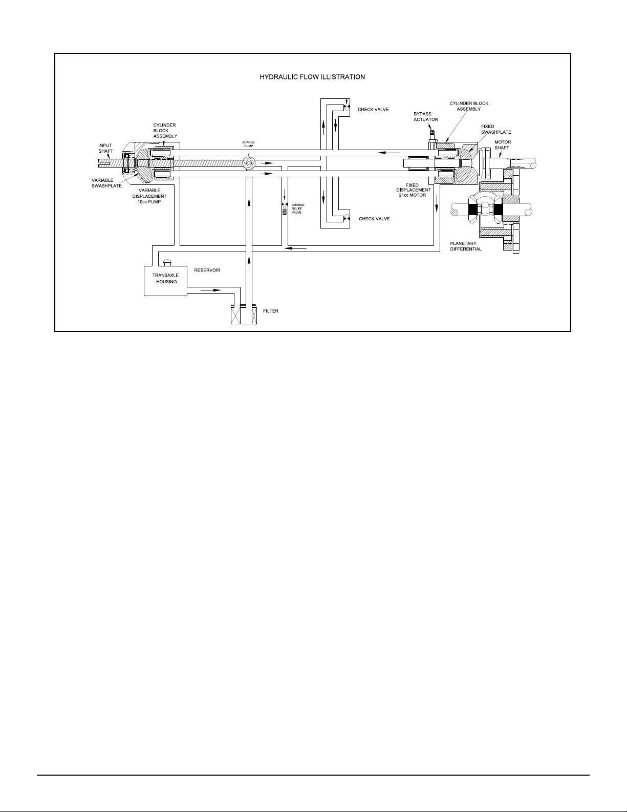
Figure 1. 310-3000 Hydraulic Flow Illustration
HYDRAULIC SCHEMATIC
Figure 1 provides an illustration of the hydraulic oil circuit. The oil supply for the hydraulic
system of the 310-3000 IHT is also utilized for
the lu bri ca tion of the planetary differential drive
gears.
The input shaft and pump cylinder block are
turned in one direction only by the engine/drive
belt/pul ley com bi na tion. Output of the oil fl ow
is con trolled by the direction and amount that
the swashplate is angled. As the pump pistons
com press they force the oil to fl ow through one
of two pas sage ways (forward or reverse) in
the center section (or valve body) to the motor
cylinder block and motor shaft. Since the motor has a fi xed dis place ment angle it is forced
to turn with the fl ow of oil. As the angle of the
swashplate is in creased the amount of oil being
pumped will increase and cause a higher RPM
output of the motor. Re vers ing the angle of the
pump swashplate will re verse the direction of
oil fl ow.
During the operation of the transaxle, fl uid
is “lost” from the hydraulic loop through leak
paths de signed into the product for lubrication
pur pos es (around pistons, under the rotating
cylinder blocks, etc.). This “lost” fl uid returns
to the trans mis sion housing and must be made
up in the loop. A charge pump is included on
the 310-3000 IHT to supply this makeup fl ow.
The make up fl ow is controlled (or directed) by
the check valves. Each check valve will either
be held opened or closed (depending upon the
direction of vehicle op er a tion) by the system
operating pressure (closed) or by charge pressure (open) from the charge pump.
The charge pump maintains a continuous fl ow
of oil as long as the input shaft is turning. All
of the oil being pulled into the charge pump
fi rst must pass through an internal fi lter. Any
oil not needed by the transmission for make
up fl ow is
310-3000 IHT 1
Page 6
dis charged through the charge relief valve. The
charge relief valve maintains the charge pres sure at no more than 40 PSI.
The motor cylinder block mounts onto the
splined motor shaft which drives the planetary
dif fer en tial gear/dif fer en tial as sem bly.
The bypass feature in the 310-3000 IHT has
a me chan i cal le ver which lifts the motor block
off of the center section running surface, allowing any oil fl owing from the pump block to
be dis charged into the housing without turning
the mo tor.
TECHNICAL
SPECIFICATIONS
Table 1. Technical Specifi cations
Overall Transaxle Reduction
30.15:1
Input Speeds
Maximum: 3600 RPM
Minimum: 1800 RPM
Maximum Tire Diameter
23 inch; 584 mm
Axle Shaft Options
Type: Keyed
Diameter: 1 inch; 25.4 mm
Type: Flanged
Diameter: Hub
Technical specifi cations for the 310-3000 IHT
are given in Table 1.
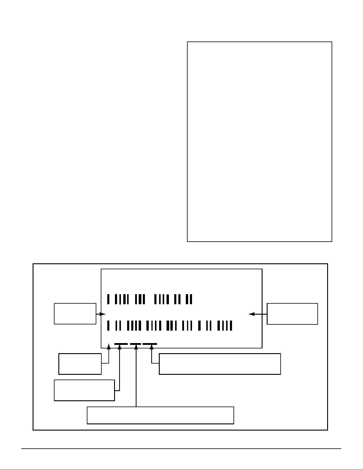
PRODUCT IDENTIFICATION
The model and confi guration of the 310-3000
IHT can be determined from the la bel shown
in Fig ure 2.
HYDRO - GEAR
SULLIVAN, IL. U.S.A.
OEM Model
Number
Year Built
165758
8 328 T1 476
(unique for that model - for that day)
Brake Type
Disc
Weight of Unit
58 lb; 26 kg
310-3000
Made in U.S.A.
Serial Number
Hydro-Gear
Number
2
Date
(Julian - day of year)
Type of Product and Build Information
Figure 2. 310-3000 Confi guration Label
310-3000 IHT
Page 7
SECTION 2. SAFETY
This symbol points out important
safe ty instructions which, if not followed, could
en dan ger the personal safety and/or property
of your self and others. Read and follow all
in struc tions in this manual before attempting
main te nance on your transaxle. When you see
this symbol - HEED ITS WARN ING.
WARNING
POTENTIAL FOR SERIOUS INJURY
Inattention to prop er safety, operation, or
maintenance pro ce dures could result in
per son al injury, or dam age to the equip ment. Before servicing or re pair ing the
310-3000 IHT, ful ly read and un der stand
the safe ty pre cau tions de scribed in this
sec tion.
PERSONAL SAFETY
Certain safety precautions must be observed
while servicing or repairing the 310-3000 IHT.
This sec tion addresses some of these pre cau tions but must not be considered an all-inclusive
source on safe ty in for ma tion. This section is
to be used in conjunction with all other safety
ma te ri al which may apply, such as:
Other manuals pertaining to this ma chine
Local and shop safety rules and codes
Governmental safety laws and reg u la tions
Be sure that you know and understand the
equip ment and the hazards associated with it.
Do not place speed above safety.
Notify your supervisor whenever you feel there
is any hazard involving the equipment or the
per for mance of your job.
Never allow untrained or unauthorized per son nel to service or repair the equipment.
Wear appropriate clothing. Loose or hanging
clothing or jewelry can be hazardous. Use the
ap pro pri ate safety equipment, such as eye
and hear ing protection, and safety-toe and
slip-proof shoes.
Never use compressed air to clean debris from
yourself or your clothing.
TOOL SAFETY
Use the proper tools and equipment for the
task.
Inspect each tool before use and replace any
tool that may be dam aged or defective.
WORK AREA SAFETY
Keep the work area neat and orderly. Be sure
it is well lit, that extra tools are put away, trash
and refuse are in the proper containers, and dirt
or debris have been removed from the working
ar eas of the ma chine.
The fl oor should be clean and dry, and all ex-
ten sion cords or similar trip hazards should be
re moved.
SERVICING SAFETY
Certain procedures may require the vehicle to
be dis abled in order to prevent possible injury
to the servicing tech ni cian and/or by stand ers.
The loss of hydrostatic drive line power may
re sult in the loss of hydrostatic braking capability. Proper brake maintenance is very important
should this condition develop.
Some cleaning solvents are fl ammable. Use
only approved cleaning materials: do not use
ex plo sive or fl am ma ble liquids to clean the
equip ment.
To avoid pos si ble fi re do not use cleaning sol-
vents in an area where a source of ignition may
be present.
Discard used cleaning material in the ap pro pri ate containers.
310-3000 IHT 3
Page 8
SECTION 3. TROU BLE SHOOT ING
WARNING
Do not attempt any ser vic ing or ad just ments with the engine run ning.
Use extreme caution while inspecting
the drive belt assembly, and all vehicle
link age!
Follow all safety pro ce dures out lined in
the ve hi cle owner’s manual!
Table 2. Troubleshooting Checklist
Possible Cause
UNIT OPERATES IN ONE DI REC TION ONLY
Control linkage bent or out of ad just ment
Drive belt slipping or pulley damaged
Oil level low or contaminated oil
Excessive loading
Brake setting incorrect
Loose parts
Bypass assembly sticking
Air trapped in hydraulic system
Repair or replace linkage
Repair or replace drive belt or pulley
UNIT IS NOISY
Fill to proper level or change oil
Reduce vehicle loading
Adjust brake to proper setting
Repair or replace loose parts
Repair or replace valve or linkage
Purge hydraulic system
In many cases problems with the 310-3000IHT
are not re lat ed to a de fec tive trans mis sion or
axle, but are caused by slip ping drive belts,
par tial ly en gaged bypass valves, and loose
or dam aged control linkages. Be sure to perform all op er a tion al checks and adjustments
outlined in Sec tion 4 be fore as sum ing the unit
is mal func tion ing. Table 2 below provides a
troubleshooting check list to help determine
the cause of op er a tion al prob lems.
Corrective Action Refer To:
Control Linkage Repair, Page 17
Pulley Repair, Page 20
Fluid Maintenance, Page 7
Vehicle Specifi cations
Brake Adjustment, Page 8
Appropriate Repair Pro ce dure
Bypass Repair, Page 16
Purging Procedure, Page 11
UNIT HAS NO/ LOW POWER
Engine RPM low
Control linkage bent or out of ad just ment
Brake setting incorrect
Drive belt slipping or pulley damaged
Oil level low or contaminated oil
Excessive loading
Bypass assembly sticking
Air trapped in hydraulic system
Debris buildup around transaxle
Brake setting incorrect
Cooling fan damaged
Oil level low or contaminated oil
Excessive loading
Air trapped in hydraulic system
Damaged seals, housing, or gaskets
Air trapped in hydraulic system
Adjust to correct setting
Repair or replace linkage
Adjust brake to proper setting
Repair or replace drive belt or pulley
Fill to proper level or change oil
Reduce vehicle loading
Repair or replace valve or linkage
Purge hydraulic system
UNIT OPERATING HOT
Clean off debris
Adjust brake to proper setting
Repair or replace cooling fan
Fill to proper level or change oil
Reduce vehicle loading
Purge hydraulic system
TRANSAXLE LEAKS OIL
Replace damaged com po nent
Purge hydraulic system
Vehicle Specifi cations
Control Linkage Repair, Page 17
Brake Adjustment, Page 8
Pulley Repair, Page 20
Fluid Maintenance, Page 7
Vehicle Specifi cations
Bypass Repair, Page 16
Purging Procedure, Page 11
Brake Adjustment, Page 8
Cooling Fan Repair, Page 20
Fluid Maintenance, Page 7
Vehicle Specifi cations Purging
Procedure, Page 11
Appropriate Repair Procedure
Purging Procedure, Page 11
4
310-3000 IHT
Page 9

SECTION 4. SERVICE AND MAINTENANCE
NOTE: Any servicing dealer attempting a war ran ty re pair must have prior
approval be fore con duct ing main te-
®
nance of a Hydro-Gear
less the ser vic ing deal er is a cur rent
Authorized Hy dro-Gear Ser vice Center.
product un-
EXTERNAL MAINTENANCE
Reference Table 4., Page 13 for tools required
in the maintenance of the 310-3000 IHT.
Regular external maintenance of the 310-3000
IHT should include the following:
1. Check the vehicle operator’s manual for
the rec om mend ed load ratings. In sure the
cur rent ap pli ca tion does not ex ceed load
rat ing.
2. Check oil level See Figure 3, Page 7.
3. Inspect the vehicle drive belt, idler pulley(s),
and idler spring(s). Insure that no belt slip page can occur. Slippage can cause low
in put RPM to the transaxle
5. Inspect the axle parking brake and ve hi cle
link age to insure proper actuation of the
park ing brake.
6. Inspect the vehicle control linkage to the
di rec tion al control arm on transaxle. Also,
in sure the con trol arm is se cure ly fastened
to the trun nion arm of the transaxle.
7. Inspect the bypass mechanism on the transaxle and ve hi cle linkage to insure it ac tu ates
and re leas es fully.
SERVICE AND
MAINTENANCE
PROCEDURES
All the service and maintenance procedures
pre sent ed on the following pages can be per formed while the 310-3000 is mounted on the
ve hi cle. Any servicing beyond those giv en must
be per formed after the unit has been removed
from the ve hi cle. Additional pro ce dures are
pro vid ed in Section 5. Repair Procedures.
4. Inspect the transaxle cooling fan for broken
or dis tort ed blades and remove any ob structions (grass clip pings, leaves dirt, etc.).
310-3000 IHT 5
Page 10
FLUIDS
FLUID CHANGE
The fl uids used in Hydro-Gear® products have
been carefully selected, and only equivalent, or
better prod ucts should be sub sti tut ed.
Typically, an engine oil with a minimum rating of
9 cSt (55 SUS) at 230° F (110° C) and an API clas si fi ca tion of SJ/CD is rec om mend ed. A 20W-50
engine oil has been se lect ed for use by the
factory and is rec om mend ed for normal op er at ing tem per a tures.
FLUID VOLUME
Fluid volume information is provided in Table
3.
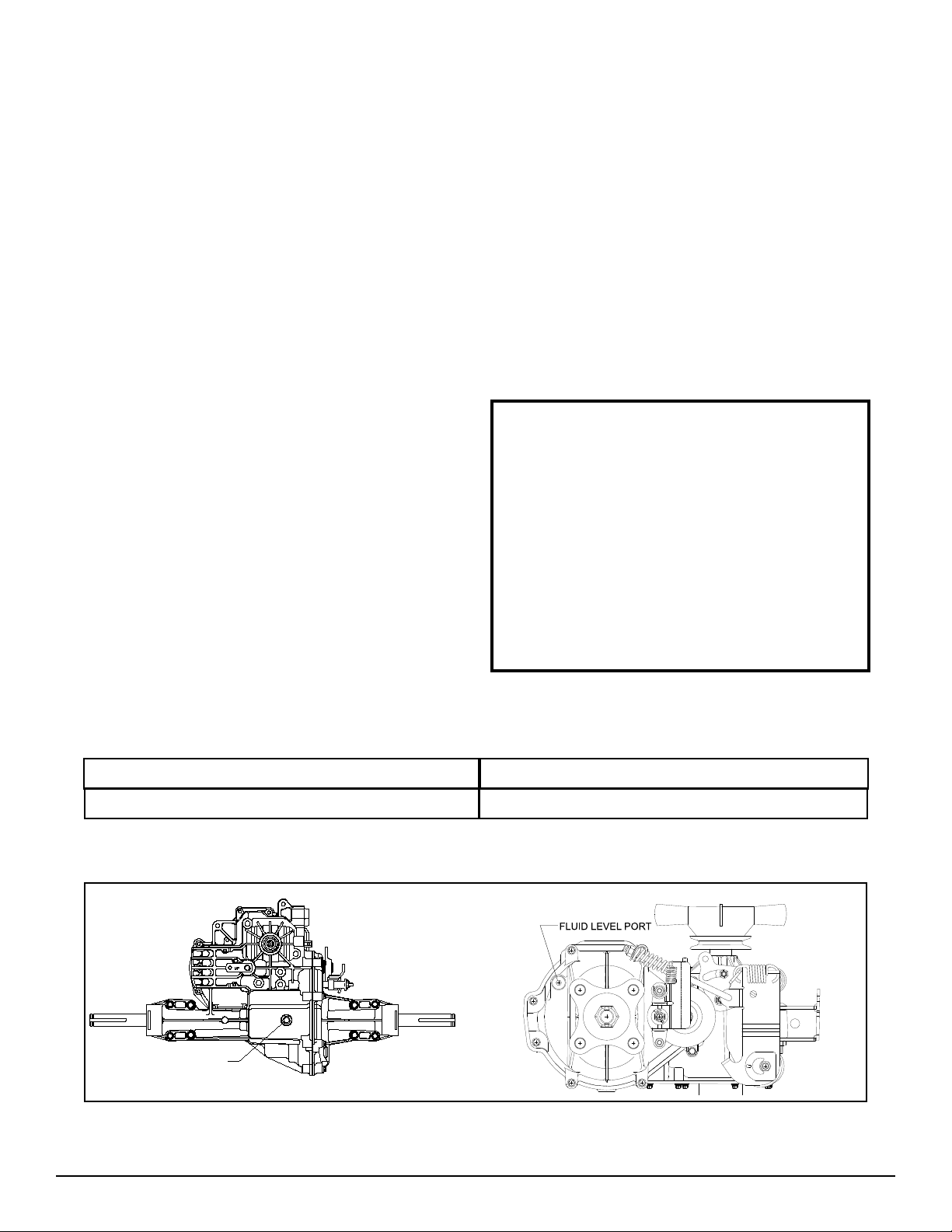
FLUID LEVEL
Certain situations may require additional fl uid to
be added or even replaced. Refer to Figure 3
for the prop er fi ll port and fl uid level port lo ca -
tions. Fill the unit until fl uid fl ows out of the fl uid
level port. Recheck the fl uid level once the unit
has been operated for approximately 1 minute.
Purging may be required. Refer to the purging
procedures, Page 11.
This transaxle is factory fi lled and does not
re quire a regular oil change. In the event of
oil con tam i na tion or degradation an oil change
may improve performance.
Using the transaxle removal procedure from
Sec tion 5, Page 12, remove the transaxle and
drain the oil from the top fl uid fi ll port. Fill unit
per Table 3, re in stall the transaxle and perform
the purging pro ce dures, Page 11.
In the event a fl uid change and fi lter inspection
is required, refer to Page 23, Disassembly/As sem bly instructions.
Caution
Do not overfi ll.
If you overfi ll the transaxle while the unit
is "cold", it may overfl ow as it reaches
normal op er at ing tem per a tures. The oil
level should not be above the man u fac tur er’s suggestions out lined in this
manual. This will al low the space need ed
for the oil to ex pand as it warms up.
Fluid Description
20W-50 engine oil
FLUID FILL PORT
Table 3. Fluid Volumes for the 310-3000 IHT
Volume
0.95 gal. (121.6 oz) (3.59 liters)
Figure 3. 310-3000 Fluid Fill and Level Ports
6
310-3000 IHT
Page 11
BRAKE MAINTENANCE
BRAKE SETTING
1. Remove the brake arm bias spring, and
then the cotter pin securing the brake castle
nut.
2. Insert a 0.015" (.381 mm) feeler gage be tween the brake disc and top brake puck,
and then set the brake by tightening or
loos en ing the cas tle nut.
3. Adjust brake gap to 0.015" (.381 mm) clear ance.
4. Install the cotter pin to secure the castle nut,
and then install the brake arm bias spring.
RETURN TO NEUTRAL SETTING
(OPTIONAL FEA TURE)
The return to neutral mechanism on the trans mis sion is designed to set the di rec tion al control
into a neutral position. An optional feature, it is
available in two versions. One version provides
hand con trol, and the other, foot control. Setting
pro ce dures are provided on pages 9 and 10.
WARNING
POTENTIAL FOR SERIOUS IN JU RY
Certain procedures require the vehicle
engine to be operated and the vehicle to
be raised off of the ground. To prevent
pos si ble injury to the servicing tech ni cian and/or by stand ers, insure the
ve hi cle is properly secured.
310-3000 IHT 7
Page 12
RETURN TO NEUTRAL SETTING
HAND CONTROL
4. Apply the vehicle brake, start the engine and
increase the throttle to full engine rpm.
WARNING
POTENTIAL FOR SERIOUS INJURY
Certain procedures re quire the vehicle
en gine to be operated and the vehicle
to be raised off of the ground. To pre vent pos si ble injury to the ser vic ing
tech ni cian and/or by stand ers, in sure
the ve hi cle is prop er ly se cured.
The return to neutral mechanism on the
trans mis sion is designed to set the di rec tion al con trol into a neutral position when the
vehicle park ing brake is en gaged. Fol low the
procedures below to properly adjust the return
to neutral mechanism on the transaxle:
1. Confi rm the transaxle is in the operating
mode (bypass disengaged). Raise the
ve hi cle’s drive tires off the ground to allow
free ro ta tion.
NOTE: It may be necessary to remove
the drive tire from the axle hub to ac cess the linkage control and the transaxle control arm.
2. Remove the Original Equipment Man u fac tur er’s (OEM’s) control linkage at the
control arm. Refer to Figure 4.
5. Check for axle rotation. If the axles do not
ro tate, go to Step 6. If the axles rotate, go
to Step 7.
6. Stop the vehicle engine. Adjust the OEM
link age according to the OEM manual. Re check ac cord ing to step 4 and 5. Stop the
vehicle en gine. Re place the brake pull rod
onto the re turn ac tu at ing arm. Install the
washer and a new cot ter pin securing the
brake pull rod to the ac tu at ing arm. Refer
to Figure 4.
7. Note the axle directional movement . Stop
the vehicle’s engine. Loosen the adjusting
puck screw until the puck can be rotated.
Rotate the adjusting puck the opposite di rec tion of the wheel rotation on the control
link age side in 5 degree increments. Tighten
the adjusting puck screw. Refer to Table 5.
Required Torque Values, Page 13. Re check
ac cord ing to step 4 and 5. Stop the vehicle
en gine. Ad just the OEM linkage according
to the OEM man u al. Recheck according
to Step 4 and 5. Stop the vehicle engine.
Re place the brake pull rod onto the return
ac tu at ing arm. Install the washer and a new
cot ter pin se cur ing the brake pull rod to the
ac tu at ing arm. Refer to Figure 4.
3. Remove the cotter pin and washer se cur ing
8
the brake pull rod to the return actuating
arm. Remove the brake pull rod from the
return actuating arm. Re fer to Figure 4.
WARNING
Do not attempt any adjustments with the
engine running. Use extreme caution
while inspecting all vehicle linkage!
Follow all safety procedures outlined in
the vehicle owner’s manual!
BRAKE PULL ROD
COTTER PIN AND WASHER
(HIDDEN)
Figure 4. Return to Neutral, Hand Control
CONTROL ARM
RETURN ACTUATING ARM
ADJUSTING PUCK
310-3000 IHT
Page 13

RETURN TO NEUTRAL SETTING
FOOT CONTROL
WARNING
POTENTIAL FOR SERIOUS IN JU RY
Certain procedures re quire the vehicle
en gine to be operated and the vehicle to
be raised off of the ground. To pre vent
pos si ble injury to the ser vic ing tech ni cian and/or by stand ers, in sure the
ve hi cle is prop er ly se cured.
The return to neutral mechanism on the trans mis sion is designed to set the di rec tion al control into a neutral po si tion when the operator
re moves their foot from the foot control. Fol low
the pro ce dures below to prop er ly adjust the return to neu tral mech a nism on the transaxle:
1. Confi rm the transaxle is in the operating
mode (bypass disengaged). Raise the
ve hi cle’s drive tires off the ground to allow
free ro ta tion.
3. Start the engine and increase the throttle to
full engine rpm.
4. Check for axle rotation. If the axles do not
ro tate, go to Step 5. If the axles rotate, go
to Step 6.
5. Stop the vehicle’s engine. Adjust the OEM
linkage according to the OEM manual. Re check according to Step 3 and 4. Stop the
ve hi cle engine. Refer to Figure 5.
6. Note the axle directional movement . Stop
the vehicle engine. Loosen the adjusting
puck screw until the puck can be rotated.
Rotate the adjusting puck the opposite direction of the wheel rotation on the control
linkage side in 5 degree increments. Tighten
the ad just ing puck screw. Refer to Table 5.
Required Torque Values, Page 13. Recheck
ac cord ing to Step 3 and 4. Stop the vehicle
engine. Ad just the OEM linkage according
to the OEM man u al. Re check according to
Step 3 and 4. Re fer to Fig ure 5.
NOTE: It may be necessary to remove
the drive tire from the axle hub to ac cess
the linkage control and the transaxle
con trol arm.
2. Remove the Original Equipment Man u fac tur er’s (OEM’s) control linkage at the control
arm. Refer to Figure 5.
WARNING
Do not attempt any adjustments with the
engine running. Use extreme caution
while inspecting all vehicle linkage!
Follow all safety procedures outlined in
the vehicle owner’s manual!
CONTROL ARM
RETURN
ACTUATING
ARM
ADJUSTING
PUCK
Figure 5. Return to Neutral, Foot Control
310-3000 IHT 9
Page 14

PURGING PROCEDURES
Due to the effects air has on effi ciency in hy-
dro stat ic drive applications, it is critical that it
be purged from the system.
These purge procedures should be im ple ment ed any time a hydrostatic system has
been opened to facilitate maintenance or any
additional oil has been added to the system.
Air creates ineffi ciency because its com pres -
sion and ex pan sion rate is higher than that of
the oil normally approved for use in hydrostatic
drive systems.
The resulting symptoms in hydrostatic systems
may be:
1. Noisy operation
2. Lack of power or drive after short term op er a tion
3. High operation temperature and ex ces sive
ex pan sion of "oil", in the latter case, oil may
over fl ow.
Before starting, make sure the transaxle/ trans mis sion is at the proper oil level. If it is not, fi ll
to the manufacturers sug ges tions outlined in
the vehicle owners manual.
The following procedures should be performed
with the ve hi cle drive wheels off the ground,
then repeated under normal op er at ing conditions.
1. With the bypass valve open and the engine
run ning, slowly move the directional control
in both forward and reverse directions 5 to 6
times, as air is purged from the unit, the oil
level will drop and bubbles may ap pear in
the oil. After stopping the engine, add oil, as
nec es sary. Fill to the level out lined in Figure
3, Page 7.
2. With the bypass valve closed and the engine
run ning, slow ly move the directional control
in both forward and reverse directions (5 to
6 times). Check the oil level, and add oil as
re quired after stopping engine.
3. It may be necessary to repeat Steps 1 and 2
until all the air is completely purged from the
system. When the transaxle moves forward
and reverse, purging is complete.
CAUTION
DO NOT OVERFILL.
If you overfi ll the transaxle while the unit
is "cold", it may overfl ow as it reaches
normal op er at ing tem per a tures. The
oil level should not be above the level
shown in fi gure 3, Page 7. This will al low
the space need ed for the oil to ex pand
as it warms up.
10
310-3000 IHT
Page 15

SECTION 5. REPAIR
NOTE: Any servicing dealer attempting
a war ran ty re pair must have prior ap prov al be fore con duct ing main te nance
®
of a Hydro-Gear
ser vic ing deal er is a cur rent Authorized
Hy dro-Gear Ser vice Center.
product un less the
GENERAL INSTRUCTIONS
Cleanliness is a primary means of assuring
sat is fac to ry life on repaired units. Thoroughly
clean all exposed surfaces pri or to any type
of main te nance. Cleaning of all parts by using a sol vent wash and air drying is usually
adequate. As with any precision equipment, all
parts must be kept free of foreign ma te ri al and
chemicals.
Protect all exposed sealing surfaces and open
cav i ties from damage and foreign material. The
external surfaces should be cleaned before be gin ning any repairs.
TRANSAXLE REMOVAL
It is necessary to remove the 310-3000 from
the ve hi cle before performing the repair procedures pre sent ed in this section. Use the following pro ce dure to prepare the unit for removal
from the ve hi cle.
1. With the vehicle wheels on the ground,
loos en the nut (119, Figure 19) Page 31,
retaining the hub (118, Fig ure 19) on the
control side of the transaxle only. Use an
air im pact wrench and a 1-1/8” socket to
loos en the hub.
2. Lift the vehicle wheels from the ground and
remove the nut completely.
3. Remove the wheel from the hub.
4. Using a wheel or gear puller, remove the
hub from the shaft.
CAUTION
Upon removal, it is recommended that all seals,
O-rings, and gaskets be re placed. During in stal la tion light ly lu bri cate all seals, O-rings, gaskets
with a clean pe tro leum jelly prior to as sem bly.
Also pro tect the inner diameter of seals by
cov er ing the shaft with a cellophane (plastic
wrap, etc.).
Parts requiring re place ment must be re placed
from the ap pro pri ate kits identifi ed in the Items
Listing, found at the end of this man u al.
REQUIRED TOOLS
A list of tools required for the repair of the 3103000 IHT is provided in Table 4, Page 13.
TORQUE SPECIFICATIONS
Torque specifi cations for fasteners used on the
310-3000 IHT are provided in Table 5.
USE CARE IN REMOVING THE HUB TO
PRE VENT CRACKING.
LIMITED DISASSEMBLY
The following procedures are presented in
the or der in which they must be performed
to com plete ly disassemble the unit. Do not
dis as sem ble the unit any farther than is necessary to ac com plish the required repairs.
Each disassembly procedure is followed by a
corresponding as sem bly procedure, and the
disassembly pro cess can be halted after any
given pro ce dure.
Assembly is accomplished by performing the
assembly por tions of the procedures. If the
unit has been completely dis as sem bled, a
summary of the assembly procedures, in the
order in which they should occur, is giv en on
Page 30.
310-3000 IHT 11
Page 16

HOW TO USE THIS
MANUAL
Many of the parts and subassemblies of this
transaxle can be removed and serviced in de pen dent ly of other components. The dis as sem bly, inspection, and as sem bly por tions of
this man u al are therefore laid out in subsections. Each as sem bly is treated as a unit, and
the dis as sem bly, inspection, and assembly
pro ce dures follow one an oth er.
Where some components and assemblies must
be removed before a given assembly can be
serviced, that information is given at the be gin ning of the disassembly instructions.
Table 4. Required Tools
Subassemblies removed to reach another
com po nent or feature need not be fully dis as sem bled. They may be reassembled intact
following the necessary repairs.
Each assembly is provided with an exploded
view showing the parts involved. At the end of
the manual, after the reassembly summary, a
com plete exploded views and items lists are
pro vid ed.
Miscellaneous
310-3000 Service & Repair Manual
Loctite
Flat Blade Screw Driver
Torque Wrench
Air Impact Wrench
Pliers
Needle Nose
External Snap Ring
Internal Snap Ring
Allen Wrenches
5 mm, 6 mm, 1/4 inch
Sockets
3/8" Drive: 7/16", 1/2", 13/16"
1/2” Drive: 9/16", 15/16", 1-1/8"
#8 Internal Torx Drive
#10 Internal Torx Drive
Socket Drivers
3/8", 1/2"
Combination Wrenches
7/16", 1/2", 9/16", 13/16", 15/16", 1-1/8"
Table 5. Required Torque Values
Operation Torque Item De scrip tion
Center Section Screws (Item #4) 525-700 lb-in (59-79 Nm) 44 Screw
Lower Housing Screws (Item # 50) 135-185 lb-in (15-21 Nm) 50 Screw
Charge Pump Cover Screws (Item # 29) 87-108 lb-in (9-12 Nm) 29 M6 x 1-22
Axle Shaft Jam Nut (Item # 73) 660-800 lb-in (75-90 Nm) 73 5/16-18
Right Hand Housing Screws (Item # 80) 230-290 lb-in (26-33 Nm) 80 5/16-18
Axle Hub Nut (Item # 119) 200-295 lb-ft (271-400 Nm) 119 3/4-16
Pulley Nut (Item # 115) 360-520 lb-in (41-59 Nm) 115 Jam Nut
Fan Screws (Item # 107) 35-50 lb-in (4-6 Nm) 107 Screw
Bypass Screw (Item # 138) 42-62 lb-in (5-7 Nm) 138 10-32 x 1/2
Torque Bracket Nut (Item # 142) 160-210 lb-in (18-24 Nm) 142 5/16-18
Control Arm Stud (Item # 36) 50-120 lb-in (6-14 Nm) 36 5/16-24
Trunnion Shaft Nut (Item # 95) 180-240 lb-in (20-27 Nm) 95 5/16-24
Control Bearing Screw(Item # 92) 190-240 lb-in (22-27 Nm) 92 Screw
Control Arm Nut (Item # 95) 85-120 lb-in (10-14 Nm) 95 5/16-24
Adjusting Puck Screw (Item # 88) 250-320 lb-in (28-36 Nm) 88 5/16-24 x 1-3/4
Brake Nuts (Item # 127) 80-120 lb-in (9-14 Nm) 127 1/4-20
12
310-3000 IHT
Page 17

BRAKE ASSEMBLY
(128), and wash er (77).
Refer to Figures 6 and 7.
DISASSEMBLY
The following procedure is for model 324-3000.
Reference microfi che for other models.
1. Remove lock nut (95), washer (77), brake
spring (134), and washer (77) from brake
pull rod (152).
2. Remove cotter pin (129), and washer (77)
from brake pull rod (152).
3. Remove brake pull rod (152) and set
aside.
4. Remove the cotter pin (129), castle nut
5. Remove brake arm (124), and brake arm
bias spring (141).
6. Remove brake anti-drag compression spring
(151), and two brake pins (125).
7. Remove upper nut (127), lock washer (126),
wash er (139), and spacer (130) which se cure brake yoke as sem bly (122).
8. Remove lower nut (127), and lock washer
(126) se cur ing brake yoke assembly
(122).
9. Remove brake yoke assembly (122), puck
plate (131), and outer brake puck (120).
10. Remove brake disc (85), and inner brake
puck (120).
REF. Part Name
2 Right Hand Housing As sem bly
77 Washer
85 Brake Disk
95 Lock Nut
120 Brake Puck
122 Brake Yoke Assembly
123 Square Head Bolt
124 Brake Arm
125 Brake Pin
126 Lock Washer
Figure 6. Brake Assembly
310-3000 IHT 13
REF. Part Name
127 Nut
128 Castle Nut
129 Cotter Pin
130 Spacer
131 Puck Plate
134 Brake Spring
139 Washer
141 Brake Arm Bias Spring
151 Anti-Drag Compression Spring
152 Brake Pull Rod
Page 18

INSPECTION
1. Inspect the brake pucks (120) for excessive
wear.
7. Install brake arm (124) onto brake yoke as sem bly.
8. Install washer (77), and castle nut (128).
2. Replace with new if necessary.
ASSEMBLY
1. Install inner brake puck (120), and brake
disc (85).
2. Assemble the brake yoke assembly, by in stall ing puck plate (131), outer brake puck
(120) into brake yoke (122).
3. Install the brake yoke assembly onto two
mounting studs on housing assembly (2).
Use of a feeler gage (0.015”) (.381 mm)
may be help ful in re tain ing the brake yoke
assembly at this step.
4. Install at upper bolt spacer (130), washer
(139), lock wash er (126), and nut (127).
5. Install at lower bolt lock washer (126), and
nut (127) to secure the brake yoke as sem bly.
6. Install brake anti-drag compression spring
(151), and two brake pins (125).
9. Insert a (0.015”) (.381 mm) feeler gage be tween brake disc (85) and top brake puck
(120). Adjust the brake by turning castle nut
(128) until it is snug but not tight against the
feeler gage. (The brake gap must be ad just ed to a (0.015”) (.381 mm) clearance.
10. Install cotter pin (129) to secure castle nut
(128).
11. Install brake arm bias spring (141) to brake
arm (124) and top brake arm bolt.
12. Install brake pull rod (152) into brake arm
(124) and ac tu at ing arm (35).
13. Secure brake rod (152) to actuating arm
(35) by in stall ing washer (77) and cotter
pin (129).
14. Secure brake pull rod (152) to brake arm by
in stall ing wash er (77), brake spring (134),
wash er (77), and lock nut (95). Set to the
di men sion shown in Figure 7.
14
5.64 + 0.06
BRAKE ROD ASSEMBLY
Figure 7. Brake Pull Rod Assembly Ad just ment
310-3000 IHT
Page 19

BYPASS ASSEMBLY
Refer to Figure 8.
DISASSEMBLY
1. Remove self tapping screw (138), and ex ten sion spring (136).
2. Remove snap ring (42), and bypass arm
(41).
3. Remove bypass lip seal (40).
INSPECTION
1. Inspect spring pin (137) for damage.
ASSEMBLY
1. If necessary, install new spring pin (137).
2. Install bypass lip seal (40).
3. Install bypass arm (41), and snap ring
(42).
4. Install self tapping screw (138), and ex ten sion spring (136).
REF. Part Name
1 Main Housing
40 Lip Seal
41 Bypass Arm
42 Retaining Ring
136 Spring
137 Spring Pin
138 Screw
Figure 8. Bypass Assembly
310-3000 IHT 15
Page 20

CONTROL ARM ASSEMBLY
Refer to Figure 9, Page 18
DISASSEMBLY
NEUTRAL ASSEMBLY
NOTE: The brake pull rod (152), washer
(77), and cotter pin (129) must be re moved before disassembling the Neu tral
Assembly (refer to Brake Assembly).
2. Inspect trunnion arm lip seal (33), and re place if nec es sary.
ASSEMBLY
CONTROL ARM ASSEMBLY
1. Install trunnion arm lip seal (33), into main
housing (1).
2. Install stud (36), per Table 5, Page 16 and
fric tion puck (37).
1. Remove bolt (88) and adjusting puck (48).
2. Remove neutral spring (46), actuating arm
(35), return arm (34), and washer (87).
CONTROL ARM ASSEMBLY
1. Remove upper lock nut (95), washer (77),
spring (93), spacer (94), washer (77), and
fric tion puck (37).
2. Remove lower lock nut (95), and trunnion
spac er (106), from the trunnion arm (31).
3. Remove control arm (26).
4. Remove friction puck (37), and stud (36), if
necessary.
INSPECTION
1. Inspect bearing (89), and replace if nec es sary. Remove bear ing by removing
coun ter sink screw (92), and washer (90).
3. Install control arm (26), onto trunnion arm
(31), and stud (36), with washer (77) and
nut (95) per Table 5, Page 13.
NOTE: If bearing (89) must be replaced,
install bear ing (89), washer (90), and
coun ter sink screw (92).
4. Install friction puck (37), washer (77), spring
(93), spac er (94), washer (77), and lock nut
(95). Tighten locknut to 120 in. lbs. (14 Nm),
then back off (1) full turn.
NEUTRAL ASSEMBLY
1. Install washer (87), return arm (34), actuating arm (35), and neutral spring (46).
2. Install adjusting puck (48), and bolt (88).
3. Reference Pages 9, 10 for proper neutral
adjustment procedures.
16
310-3000 IHT
Page 21

REF. Part Name
26 Control Arm
31 Trunnion Arm
32 Trunnion Bushing
33 Trunnion Arm Lip Seal
34 Return Arm
35 Actuating Arm
36 Stud
37 Friction Puck
46 Spring
48 Adjusting Puck
Figure 9 Control Arm Assembly
REF. Part Name
77 Washer
87 Washer
88 Screw
89 Bearing
90 Locating Spacer
92 Countersink Screw
93 Spring
94 Spacer
95 Locknut
106 Trunnion Spacer
310-3000 IHT 17
Page 22

TORQUE BRACKET
ASSEMBLY
Refer to Figure 10.
DISASSEMBLY
1. Remove lock nut (142), and bolt (143), from
torque brack et (102).
2. Remove torque bracket (102), from main
hous ing (1).
ASSEMBLY
1. Install torque bracket (102), onto main hous ing (1).
2. Install lock nut (142), and bolt (143), to se cure torque brack et (102) to main housing
(1). Reference Table 5, Page 13 for torque
values.
REF. Part Name
1 Main Housing
102 Torque Bracket
142 Lock Nut
143 Bolt
Figure 10. Torque Bracket Assembly
18
310-3000 IHT
Page 23

FAN AND PULLEY
ASSEMBLY
Refer to Figure 11.
DISASSEMBLY
1. Remove jam nut (115) from input shaft
(12).
2. Remove fan/pulley assembly (104), (103),
(107).
INSPECTION
1. Inspect fan (104) for broken and/or dam aged blades. If necessary to replace fan
(104), re move screws (107), and fan (104),
from pul ley (103).
ASSEMBLY
1. Install fan/pulley assembly (104), (103),
(107) onto in put shaft (12).
2. Secure fan/pulley assembly (104), (103),
(107) onto shaft (12) by installing jam nut
(115), per table 5, Page 13.
REF. Part Name
1 Main Housing
12 Input Shaft
103 Pulley
104 Fan
107 Screw
115 Jam Nut
Figure 11. Fan and Pulley Assembly
310-3000 IHT 19
Page 24

INPUT SHAFT ASSEMBLY
Refer to Figure 12.
DISASSEMBLY
1. Drain the oil from the transaxle.
2. Remove snap ring (7), input shaft lip seal
(5), and spacer (4).
3. Remove input shaft assembly (12), (8),
(6).
4. Remove washer (13) from cavity.
INSPECTION
1. Inspect bearing (8) for damage and, if
nec es sary replace bearing, remove wire
re tain ing ring (6) and bear ing (8) from in put
shaft (12).
ASSEMBLY
1. Carefully install washer (13) onto top of
spring in cav i ty.
REF. Part Name
1 Main Housing
4 Spacer
5 Lip Seal
6 Wire Retaining Ring
7 Snap Ring
8 Ball Bearing
12 Input Shaft
13 Block Thrust Washer
Figure 12. Input Shaft Assembly
2. Press bear ing (8) onto in put shaft (12) and
secure by in stall ing wire retaining ring (6).
3. Install input shaft assembly (12), spacer (4),
and lip seal (5) into input bearing bore of
main housing (1).
4. Secure input shaft assembly (12) by in stall ing retaining ring (7).
20
310-3000 IHT
Page 25

CHARGE PUMP ASSEMBLY
Refer to Figure 13.
DISASSEMBLY
Note: Before disassembling, note the
ori en ta tion of the charge pump cover
(54). Scribe or mark the charge pump
cover (54) for correct orientation during
as sem bly.
1. Remove two screws (29) from the charge
pump cover (54), and remove charge pump
cover (54).
2. Remove o-ring (53) and gerotor assembly
(52).
INSPECTION
1. Inspect gerotor assembly (52), cavity of
charge pump cov er (54), plate on which
cov er is mounted for damage or ex ces sive
wear.
REF. Part Name
1 Main Housing
29 Screw
52 Gerotor Assembly
53 O-ring
54 Gerotor Cover
Figure 13. Charge Pump Assembly
ASSEMBLY
1. Install gerotor assembly (52) onto input shaft
(12) (not shown).
2. Install new O-ring (53) into charge pump
cov er (54).
3. Install charge pump cover (54), making sure
it is prop er ly oriented.
4. Secure charge pump cover (54) by installing
two screws (29), per Table 5, Page 13.
310-3000 IHT 21
Page 26

LOWER HOUSING/FILTER/
MANIFOLD ASSEMBLY
Refer to Figure 14.
NOTE: Charge Pump assembly must be
removed before the following steps can
be performed.
DISASSEMBLY
1. Remove the eleven housing screws (50) and
low er cover (51), and remove sealant.
2. Remove screw O-rings (157).
3. Remove spring (145) and ball (146).
4. Remove fi lter (55) and charge manifold
(56).
5. Remove O-ring (144).
INSPECTION
1. Inspect fi lter (55) and manifold (56), replace
if necessary.
2. Inspect O-ring (144) and screw O-rings
(157).
ASSEMBLY
1. Install O-ring (144) onto center section as sem bly (3), re fer to Figure 134
2. Install fi lter (55) and charge manifold (56).
3. Install spring (145) and ball (146).
4. Install screw O-rings (157).
5. Dry fi t lower cover (51) on housing, using
screws (29) to align cover and manifold
(56).
6. Remove screws (29) and cover (51). Apply
sealant (79) to lip of main hous ing (1).
REF. Part Name
1 Main Housing
29 Capscrew
49 Not Used
50 Screws
51 Lower Cover
52 Gerotor Assembly
53 O-Ring
54 Gerotor Cover
Fig ure 14. Lower Housing/Filter/Man i fold Assembly
REF. Part Name
55 Filter
56 Charge Manifold
144 O-Ring
145 Spring
146 Ball
156 Manifold O-Ring
157 Screw O-Ring
7. Reinstall cover (51) and screws (29), ref-
8. Secure lower cover (51) to main housing
22
er ence Table 5, Page 13.
(1) by in stall ing the eleven housing screws
(50), reference Table 5, Page 13.
310-3000 IHT
Page 27

PLANETARY DIFFERENTIAL
ASSEMBLY
2. Remove all sealant from both hous ings and
in spect seal lands for damage when clean ing.
Refer to Figure 15, next page.
NOTE: Brake Assembly, and optional Return to Neutral have to be re moved be fore
the fol low ing steps can be per formed.
DISASSEMBLY
1. Remove the axle hub assembly (118) on con trol
side by re mov ing nuts (119), and hub as sem blies (118).
2. Remove the eight torx head screws (80) that
secure the R.H. hous ing assembly (2).
3. Remove R.H. housing assembly (2), while
holding axle shaft (76) in place.
4. Remove the two housing pins (117).
5. Remove washer (71) from axle shaft (76).
6. Re move spur gear (60), and thrust plate
(62).
3. If miter gear (65) needs re placed, remove jam
nut (73) from axle shaft (76).
ASSEMBLY
1. If necessary, install L.H. Axle shaft assembly
(76) into main hous ing (1). If necessary, re as sem ble axle shaft assembly (76) by in stall ing
wash er (70), miter gear (65), and jam nut (73)
onto axle shaft (76).
2. Install differential thrust plate (68) into main
housing (1).
3. Install planetary carrier (64) into main hous ing
(1).
4. Reassemble the two miter gears (66) onto differential shaft (67), and install assembly into
planetary carrier (64).
5. Install 51T ring gear (63) into main housing
(1).
7. Remove 21T sun gear (61), and sleeve bear ing
(96).
8. Remove the planetary gears (59).
9. Remove washer (70), and axle shaft (76).
10. Remove the four carrier pins (58) from plan e tary car ri er (64).
11. Remove 51T ring gear (63) from main hous ing
(1).
12. Remove the two miter gears (66), and dif fer en tial shaft (67).
13. Remove planetary carrier (64) and dif fer en tial
thrust plate (68).
14. If necessary, remove the second axle shaft
assembly (76) from main hous ing (1).
15. Remove the seal from the shaft, if necessary.
INSPECTION
1. Inspect all gears for excessive wear or dam age
and re place if necessary.
6. Install the four carrier pins (58) into planetary
carrier (64).
7. If necessary, re as sem ble axle shaft as sem bly
(76) by in stall ing washer (70), miter gear (65),
and jam nut (73) onto axle shaft (76).
8. Install R.H. Axle shaft assembly (76) partway
into as sem bled differential components.
NOTE: It will be necessary to support the RH
axle shaft in the partially installed position
while steps 9 through 16 are completed.
9. Assemble sleeve bearing (96) and sun gear
(61), slid ing them onto R.H. axle shaft. The
smaller diameter on the sun gear OD should
be “IN”.
10. Install the four 15T planetary gears (59) on
pins (80) . Make sure the planetary gears are
properly aligned with the sun gear. Mate the
bevel gear on the end of the R.H. axle shaft
with the bevel gears in the differential assembly. Continue to support the R.H. axle shaft.
310-3000 IHT 23
Page 28

REF. Part Name
1 Main Housing
2 R.H. Housing Assembly
58 Carrier Pin
59 Planetary Gears
60 67t Spur Gear
61 21t Sun Gear
62 Planetary Thrust Plate
63 51t Ring Gear
64 Planetary Carrier
65 Differential Miter Gear
66 Differential Miter Gear
67 Differential Shaft
68 Differential Thrust Plate
D
C
B
A
REF. Part Name
70 Washer
71 Washer
63 51t Ring Gear
64 Planetary Carrier
65 Differential Miter Gear
66 Differential Miter Gear
73 Hex Jam Nut
76 Axle Shaft
80 Torx Head Screws
96 Bearing Sleeve
REF. Part Name
117 Housing Pin
118 Axle Hub Assembly
119 Hex Nut
D
B
C
A
Figure 15. Planetary Differential Assembly
11. Install the planetary thrust plate (62).
12. Install the 67T spur gear (60) onto the
21T sun gear (61).
13. Slide washer (71) onto axle shaft (76).
14. Install the two housing pins (117) into the
main housing.
15. Apply a bead of sealant to the R.H. hous-
ing (2).
24
16. Install R.H. housing (2) by sliding it down
the axle shaft (76), over motor shaft as-
sembly (24, Figure 15) and onto main
housing (1).
17. Secure housings by installing the eight
housing screws (80), per Table 5, Page 13.
18. After the transaxle has been installed in
the vehicle, install the axle hub assem-
blies (118), according to the instructions
in "Transaxle installation," Page 30.
310-3000 IHT
Page 29

MOTOR/CENTER SECTION/
PUMP ASSEMBLY
Refer to Figures 16 and 17, (next pages).
NOTE: Brake Assembly, Input As sem bly,
Charge Pump Assembly, and Low er
Hous ing/Filter/Manifold As sem bly have
to be removed before the fol low ing steps
can be per formed.
DISASSEMBLY
1. Remove washer (82), snap ring (83), washer
(82), 16T pin ion gear (28), spacer (27), and
shaft (28).
(25) for ex ces sive wear (grooving or smearing).
2. Inspect each piston (23), spring (18), and
pis ton seat (22) in the mo tor cylinder block
as sem bly.
3. Inspect seal lands of the 21cc motor cylinder block as sem bly (21) for excessive wear
(groov ing or smearing).
4. Inspect the two running surfaces of center
section as sem bly (3) for excessive wear
(groov ing or smearing). Abnormal wear
pat terns will usually be visible. Any wear
de tect able when a fi ngernail is dragged
across the surface is cause for rejection.
2. Remove motor thrust bearing re tain er
(57).
3. Remove motor thrust bearing (25), and 21cc
motor cyl in der block assembly (21).
4. Remove each piston (23), spring (18), and
piston seat (22) from the 21cc motor cylinder
block assembly.
5. Remove bypass plate (38) from center sec tion assembly (3).
6. Remove the three screws (44) from center
section as sem bly (3).
7. Lift center section assembly (3) out of main
housing (1).
8. Remove the two center section assembly
pins (43).
9. Remove bypass actuator (39) from the cen ter section (3).
10. Remove 10cc pump cylinder block as sem bly
(15).
5. Inspect each piston (17), spring (18), piston
seat (16).
6. Inspect seal lands of 10cc pump cylinder
block assembly (15) for excessive wear
(groov ing or smearing).
ASSEMBLY
1. Install pump cylinder block thrust washer
(13) and spring (14) onto input shaft assembly (12).
2. Install piston washers (18), springs (17), and
pistons (18) in cylinder block (15).
3. Install pump cylinder block assembly (15).
Be sure spring tension is even around the
entire block.
4. Install the two center section assembly pins
(43).
5. Install center section assembly (3) into main
housing (1). Make sure center section seats
fully on its mating surface.
11. Remove each piston (17), spring (18), pis ton
seat (16) from the 10cc pump cylinder block
as sem bly (21).
12. Remove block spring (14), and block thrust
washer (13) from shaft (12, Figure 10)
6. Secure center assembly section (3) by in stall ing three screws (44) reference Table
5, Page 13. Ap ply a few drops of loctite on
screws when in stall ing.
7. Install bypass plate (38) into center section
assembly (3).
INSPECTION
1. Inspect running surface of thrust bearing
310-3000 IHT 25
Page 30

NOTE: To hold bypass plate (38) in po si tion, apply a small drop of grease to its
slot before installing.
8. Install spacer (27), 16T pinion gear (28),
wash er (82), snap ring (83), and washer
(82) onto motor shaft (24).
13. Again using the assembly tool to compress
pistons (22), slide thrust bearing (25), be hind
the tool, into its cavity in front of the cyl in der
block (21) and as sem bled pistons.
NOTE: The thick race of thrust bearing
(25) must face the pis tons.
9. Insert the motor shaft assembly far enough
to seat the motor cylinder block (21).
10. Install piston washers (18), springs (17), and
pistons (16) in cylinder block (21).
11. If not already available, make an assembly
tool from 28 ga. sheet metal as shown in
Fig ure 16. The assembly tool must be free
of burrs and rough edges.
12. Using the assembly tool to compress pis tons
(22), install cylinder block assembly (21).
Be careful not to dislodge bypass plate
(38) when installing the cylinder block as sem bly.
Break sharp edges, both sides
14. While holding the cylinder block assembly
(21) and the thrust bearing (25) in place,
with draw the assembly tool from between
the thrust bearing and the pistons.
15. Install motor thrust bearing retainer (57)
16. Reassemble the planetary differential as sem bly and in stall removed components
as di rect ed in their respective assembly
pro ce dures.
Use 28 gauge
sheet metal
2.250 inch
1.125 Radius
6.000 inch
Figure 16. Motor Cylinder Block Assembly Tool
26
310-3000 IHT
Page 31

REF. Part Name
1 Main Housing
3 Center Section Assembly
13 Block Insert Washer
14 Block Spring
15 10cc Cylinder Block
16 Pistons
17 Springs
18 Piston Washers
19 Block Spring
Figure 17. Motor/Center Section/Pump Assembly
REF. Part Name
20 Bushing
21 21cc Cylinder Block
22 Pistons
23 Springs
24 Motor Shaft
25 Thrust Bearing
27 Spacer
28 16t Pinnion Gear
REF. Part Name
38 Bypass Plate
43 Pin
44 Screws
53 O-Ring
57 Bearing Retainer
82 Washer
83 Retaining Ring
144 O-ring
310-3000 IHT 27
Page 32
DIRECTIONAL CONTROL
ASSEMBLY
Refer to Figure 18.
NOTE: The Motor/Center Section/Pump
Assembly must be disassembled before
this procedure can be completed.
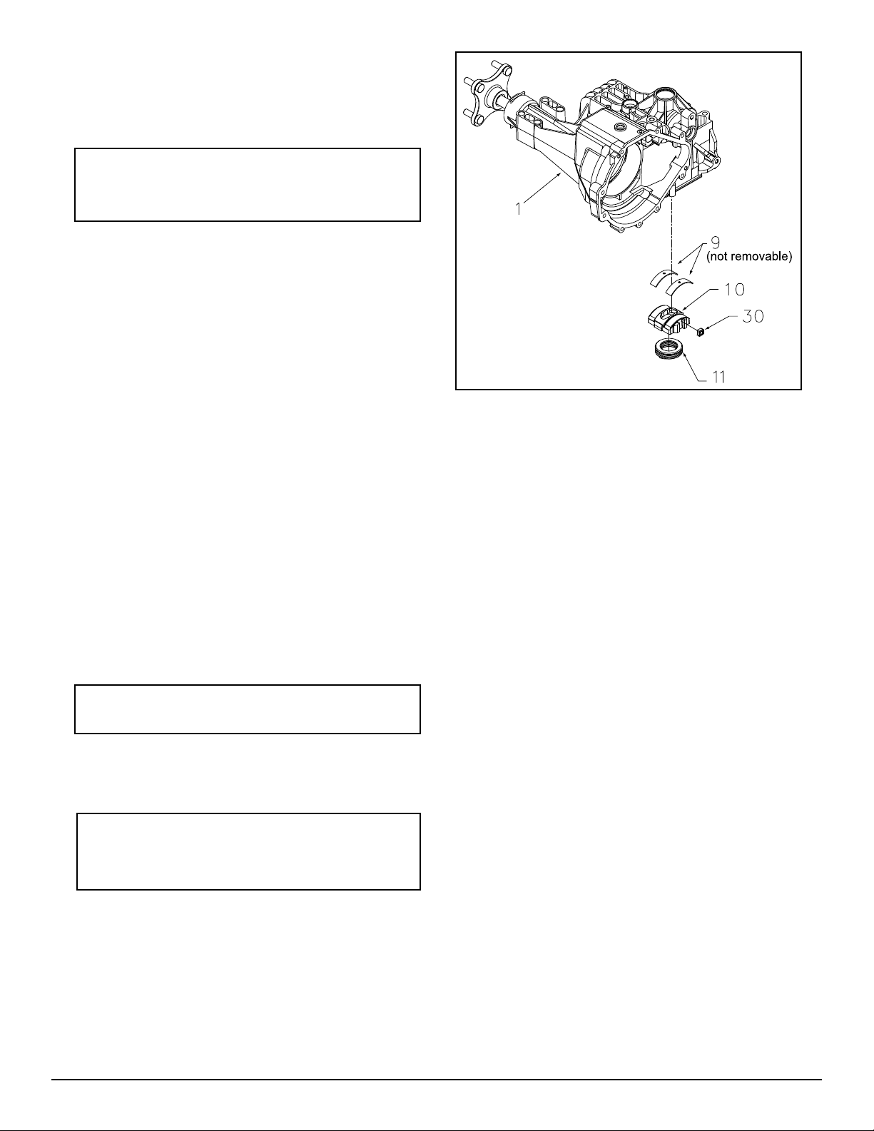
DISASSEMBLY
1. Remove swashplate assembly (10). Dis as sem ble swashplate assembly by removing
thrust bearing (11) from swashplate (10).
The thick race of thrust bearing must face
pis tons.
2. Remove slot guide (30).
INSPECTION
1. Visually inspect (in place) the two cradle
bear ings (9), which are staked in upper
housing. Do not remove the Cradle Bearings (9) from housing (1).
ASSEMBLY
1. Install slot guide (30).
2. As sem ble swashplate as sem bly (10) by in stall ing thrust bearing (11) into swashplate
(10).
REF. Part Name
1 Main Housing
9 Cradle Bearing
10 Variable Swashplate
11 Thrust Bearing
30 Slot Guide
Figure 18. Directional Control Assembly
Note: As sem ble thrust bear ing with thick
race fac ing pistons.
3. Install swashplate assembly (10) into main
NOTE: When in stall ing swashplate as sem bly (10), use fl at head screwdriver
to hold slot guide (30) in place.
28
housing (1). The swashplate (10) will couple
with slot guide (30).
310-3000 IHT
Page 33

TRANSAXLE INSTALLATION
ASSEMBLY AFTER A
Use the following pro ce dure to complete in stal la tion of the transaxle on the ve hi cle.
1. Install and secure the transaxle on the ve hi cle according to instructions in the vehicle
own er’s manual.
2. Install the hub assembly (118, Figure 13) on
the shaft. Install hex nut (119, Figure 13).
3. With the vehicle raised, install the wheel
on the hub, and retain with the wheel lug
nuts.
4. Lower the vehicle wheels to the ground, and
torque the nut re tain ing the hub to 290 to
295 lb.-ft., using an air im pact wrench.
5. Tighten the wheel lug nuts.
COMPLETE TEAR-DOWN
If the unit has been torn down completely, the
fol low ing sum ma ry identifies the assembly
pro ce dures necessary to com plete ly assemble
the unit, in the order they must be completed.
Each as sem bly procedure is located by a page
ref er ence.
The part reference numbers provided in each
assembly pro ce dure are keyed to the individual
exploded views, and are also keyed to the com plete unit exploded view, Figure 19.
1. Assemble the Directional Control Assembly
(Page 29).
2. Assemble the Motor/Center Section/Pump
Assembly (Page 26,27,28).
3. Assemble the Planetary Differential As sem bly (Page 24,25).
4. Assemble the Lower Housing/Filter/Man i fold
Assembly (Page 23).
5. Assemble the Charge Pump Assembly
(Page 22).
6. Assemble the Input Shaft Assembly (Page
21).
7. Assemble the Fan and Pulley Assembly
(Page 20).
8. Assemble the Torque Bracket Assembly
(Page 19).
9. Assemble the Control Arm Assembly (Page
17,18).
10. Assemble the Bypass Assembly (Page
16).
11. Assemble the Brake Assembly (Page
14,15).
310-3000 IHT 29
Page 34
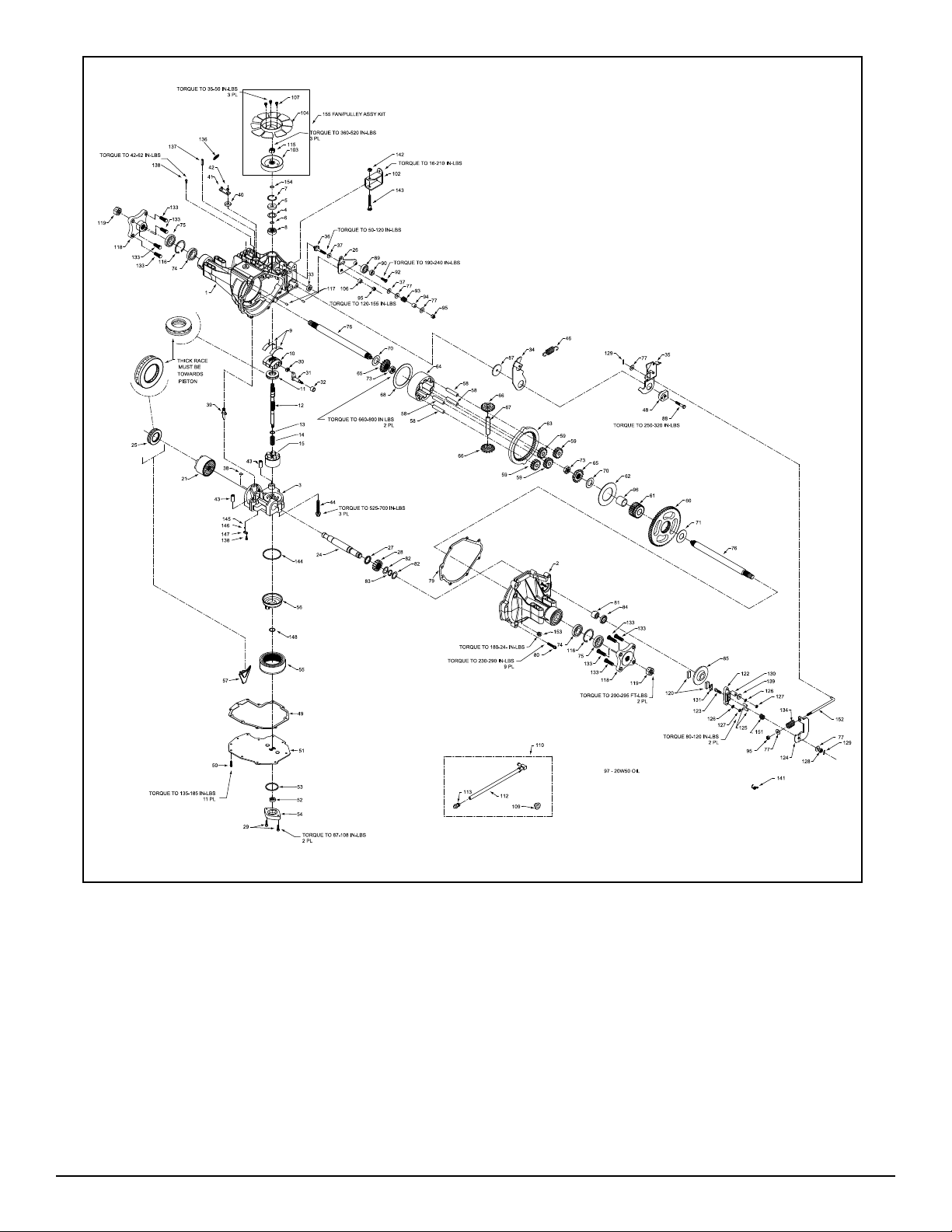
Figure 19. 310-3000 IHT Exploded View
30
310-3000 IHT
Page 35

ITEMS LIST
Part numbers are not provided in this manual. See Service Schematic or Distributor for part numbers.
NO. DESCRIPTION
1 Main Housing Assembly
2 R.H. Housing Assembly
3 Center Section Assembly
4 Spacer
5 Lip Seal
6 Wire Retaining Ring
7 Retaining Ring
8 Ball Bearing
9 Cradle Bearing
10 Variable Swashplate
11 Thrust Bearing
12 Input Shaft
13 Block Thrust Washer
14 Block Spring
15 10cc Cylinder Block Assembly
21 21cc Cylinder Block Assembly
24 Output (Motor) Shaft
25 Thrust Bearing
26 Control Arm
27 Spacer
28 16T Pinion Gear
29 Cap Screw M6 X 1-22
30 Slot Guide
31 Trunnion Arm
32 Trunnion Bushing
33 Lip Seal
34 Return Arm
35 Actuating Arm
36 Stud 5/16 - 24
37 Friction Puck
38 Bypass Plate
39 Bypass Actuator
40 Lip Seal
41 Bypass Arm
42 Retaining Ring
43 Pin
44 Screw
46 Neutral Spring
48 Adjusting Puck
50 Screw , Self-Tapping
51 Lower Cover
52 Gerotor Assembly
53 O-Ring
54 Gerotor Cover
55 Filter
56 Charge Manifold
57 Retainer, Motor Bearing
58 Pin, Carrier
59 15T Planet Gear
60 67T Spur Gear
61 21T Sun Gear
62 Planet Thrust Plate
63 51T Ring Gear
64 Planetary Carrier
65 Miter Gear, Differential (SPLINED)
66 Miter Gear, Differential
67 Shaft , Differential
68 Differential Thrust Plate
69 Flange Bearing
70 Washer
71 Washer
73 Hex Jam Nut, 5/8 - 18
74 Ball Bearing 6205-1
75 Seal, 1” ID X 2.0472” X 0.375”
76 Shaft, Axle
77 Washer
NO. DESCRIPTION
79 Gasket Material/Sealant
80 Torx Head Screw 5/16 - 18
81 Needle Bearing
82 Washer
83 Retaining Ring
84 Lip Seal
85 Brake Disc
87 Washer
88 Screw 5/16 - 24 X 1-3/4
89 Bearing
90 Spacer, Locating
91 O-Ring
92 Countersunk Screw
93 Spring Spacer
94 Spacer
95 Nut, Hex Lock 5/16 - 24
96 Sleeve Bearing
97 20W50 Oil
102 Torque Bracket
103 Pulley
104 Fan
106 Spacer, Trunnion
107 Screw
109 Vent Bushing
110 Fitting Kit
111 Cap-Vent Assembly
113 Hose/ Fitting Assembly
115 Jam Nut
116 Retaining Ring
117 Std Hlds Pins
118 Hub Assembly 7/16 - 14
119 Nut, Hex 3/4 - 16
120 Puck, Brake
121 Rib Neck Bolt, 2”
122 Brake Yoke
123 Bolt, Square-Head
124 Arm, Brake
125 Pins, Brake
126 Lock Washer, 1/4"
127 Nut, 1/4 - 20
128 Nut, Castle
129 Cotter Pin
130 Spacer
131 Puck Plate
132 Rib Neck Bolt, 3”
133 Wheel Stud 7/16-14
134 Brake Spring
136 Extension Spring
137 Spring Pin
138 Screw , Stap 10-32 X .5
139 Washer
141 Spring, Brake Arm Bias
142 Hex Lock Nut 5/16 - 18
143 Bolt 5/16 -15 X 2.5
144 O-Ring
145 Spring, Relief
146 Ball , 7/16
151 Compression Spring Brake Anti-Drag
152 Brake Pull Rod
153 Plug, Straight Thread
154 Wire Retaining Ring
155 Fan/ Pulley Assembly
157 Screw O-Ring
180 Manifold Kit
202 Manifold O-Ring Kit
203 Seal Kit (310-3000)
310-3000 IHT 31
Page 36

SECTION 6. GLOSSARY OF TERMS
Axial Piston: Type of design for hydraulic motors and pumps in which the pistons are arranged
parallel with the spindle (input or output shaft).
Bantam Duty: A descriptive term relating to the product capacity (meaning: light duty).
Bypass Valve: A valve whose primary function is to open a path for the fl uid to bypass the motor
or pump. Also referred to occasionally as the freewheel valve or dump valve.
Case Drain Line (Return Line): A line returning fl uid from the component housing to the res-
er voir.
Cavitation: A concentrated gaseous condition within the fl uid causing the rapid implosion of a
gas eous bubble.
Center Section: A device which acts as the valve body and manifold of the transmission.
Charge Pump: A device which supplies replenishing fl uid to the fl uid power system (closed
loop).
Charge Pressure: The pressure at which replenishing fl uid is forced into a fl uid power system.
Charge Relief Valve: A pressure control valve whose primary function is to limit pressure in the
charge circuit.
Check Valve: A valve whose primary function is to restrict fl ow in one direction.
Closed Loop: A sealed and uninterrupted circulating path for fl uid fl ow from the pump to the
motor and back.
Decay Rate: The ratio of pressure decay over time.
End Cap: See “Center Section”
Entrained Air: A mechanical mixture of air bubbles having a tendency to separate from the liquid
phase.
Gerotor: A positive displacement pump frequently used as a charge pump.
Hydraulic Motor: A device which converts hydraulic fl uid power into mechanical force and mo-
tion by transfer of fl ow under pressure.
Hydraulic Pump: A device which converts mechanical force and motion into hydraulic fl uid pow er
by producing fl ow.
Hydrostatic Pump: See “Hydraulic Pump”
32
310-3000 IHT
Page 37

Hydrostatic Transaxle: A multicomponent as sem bly including a gear case and a hydrostatic
trans mis sion.
Hydrostatic Transmission: The combination of a hy drau lic pump and motor in one housing to
form a de vice for the control and transference of power.
Inlet Line: A supply line to the pump.
Integrated Hydrostatic Transaxle (IHT): The com bi na tion of a hydrostatic transmission and
gear case in one housing to form a complete transaxle.
Manifold: A conductor which provides multiple con nec tion ports.
Neutral: Typically described as a condition in which fl uid fl ow and system pressure is below that
which is required to turn the output shaft of the motor.
Pressure Decay: A falling pressure.
Priming: The fi lling of the charge circuit and closed loop of the fl uid power system during start
up, fre quent ly achieved by pressurizing the fl uid in the inlet line.
Purging: The act of replacing air with fl uid in a fl uid power system by forcing fl uid into all of the
com po nents and allowing the air a path of es cape.
Rated Flow: The maximum fl ow that the power sup ply system is capable of maintaining at a
spe cifi c op er at ing pressure.
Scoring: Scratches in the direction of motion of me chan i cal parts caused by abrasive con tam i nants.
Swash Plate: A mechanical device used to con trol the displacement of the pump pistons in a
fl uid power sys tem.
System Charge Check Valve: A valve con trol ling the replenishing fl ow of fl uid from a charge
circuit to the closed loop in a fl uid power system.
System Pressure: The pressure which over comes the total resistance in a system, in
clud ing
all losses.
Valve: A device which controls fl uid fl ow di rec tion, pressure, or fl ow rate.
Variable Displacement Pump: A pump in which the displacement per cycle can be varied.
Volumetric Displacement: The volume for one rev o lu tion.
310-3000 IHT 33
Page 38

NOTES
34
310-3000 IHT
Page 39

NOTES
310-3000 IHT 35
Page 40

© 2008 HYDRO-GEAR
Rev. P2
Printed in U.S.A.
 Loading...