

Page 1

SERIES 3000
SERVICE MANUAL
770-10227
Page 2

Series 3000 Technical Handbook
Table of Contents
Section
Pre-Delivery Check List and Service Specifications 1999 ................................................................................1
Engineering Updates 1999................................................................................................................................2
Fender Removal and Reinstallation ..................................................................................................................3
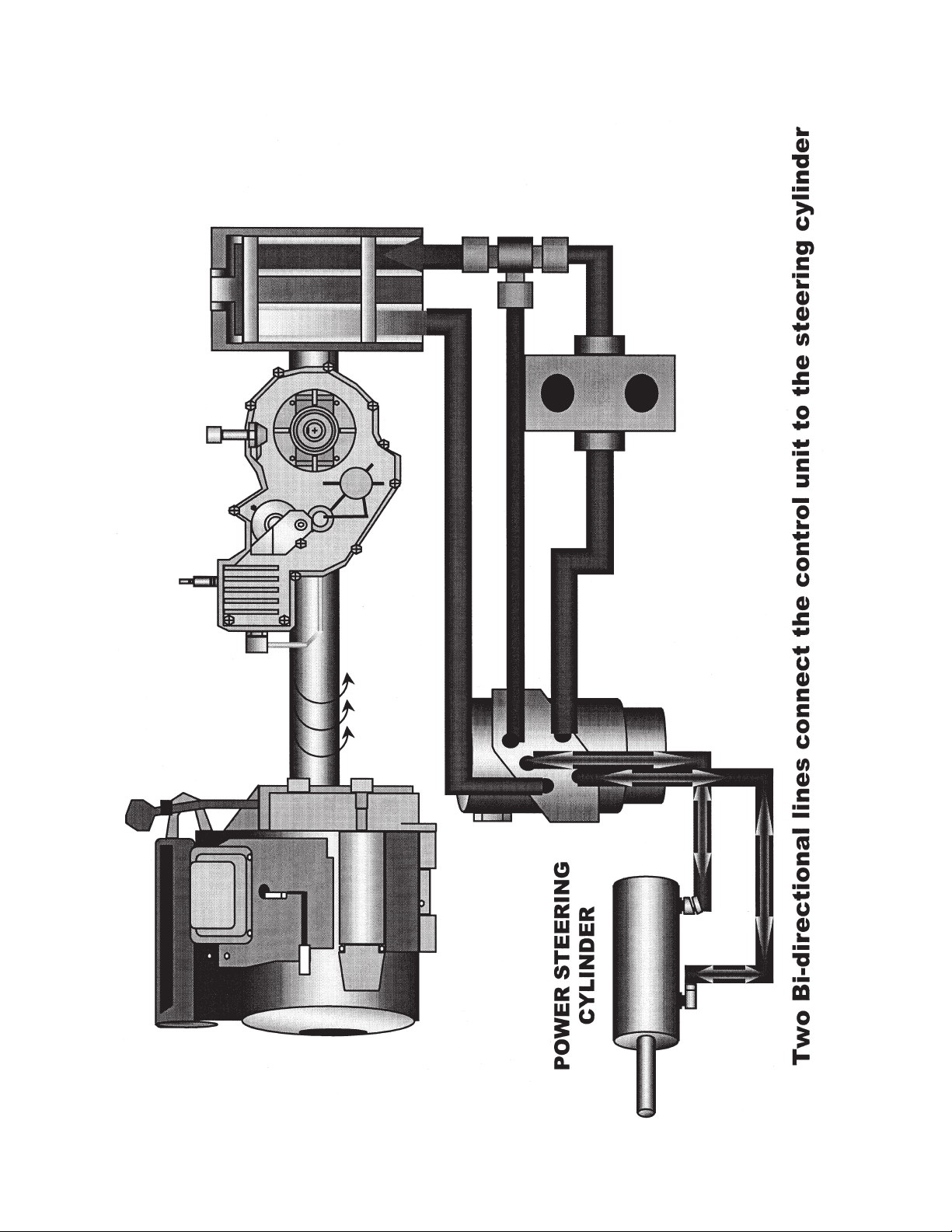
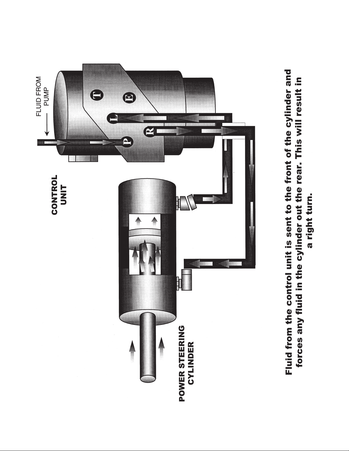
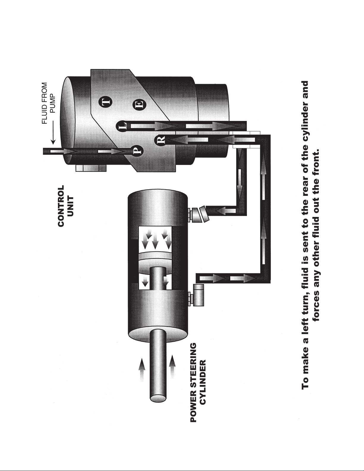
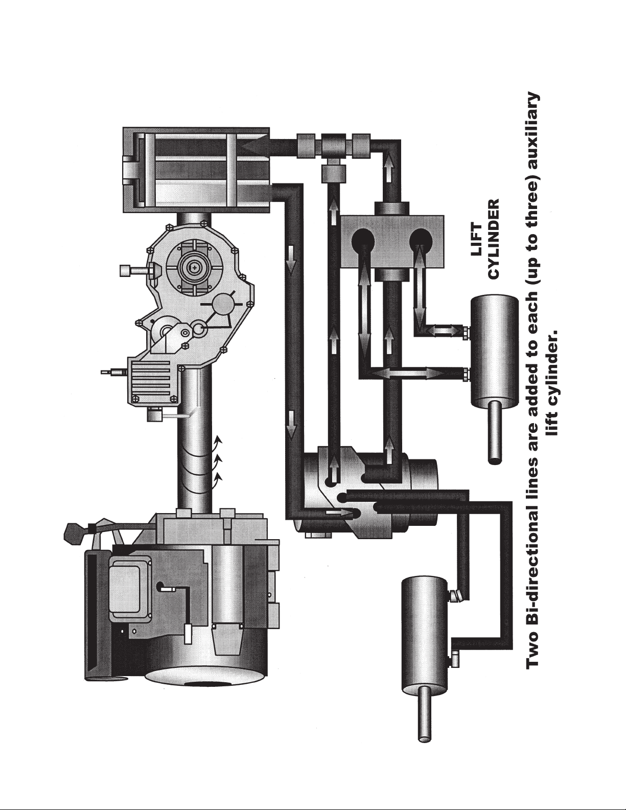
Hydraulic Step by Step Flow Charts .................................................................................................................4
Power Steering Cylinder Removal and Replacement .......................................................................................5
Power Steering Pump Disassemble, Inspect and Reassemble ........................................................................6
Center Lift Cylinder Removal and Replacement ...............................................................................................7
Pump Adapter Removal and Replacement.......................................................................................................8
BDU-21L-500 Pressure Test Procedure ...........................................................................................................9
Hydraulic Steering Pump Removal and Replacement ....................................................................................10
Hydraulic Valve Removal and Replacement...................................................................................................11
Engine Removal and Replacement.................................................................................................................12
Transmission Removal and Installation ..........................................................................................................13
Transmission Inspection and Disassembly .....................................................................................................14
Transmission Reassembly ..............................................................................................................................15
Neutral Control Adjustment .............................................................................................................................16
3000 Series Electrical .....................................................................................................................................17
BDU-21L Transmission ...................................................................................................................................18
Page 3

Pre- Delivery Check List
1000, 1500, 2000, 2500, 3000 Series
CUSTOMER NAME_____________________________
ADDRESS____________________________________
CITY_________________________________________
STATE________________________ZIP____________
HOME PHONE NUMBER________________________
ENGINE INFORMATION:
ENGINE MAKE__________________________________
ENGINE MODEL NUMBER_________________________
ENGINE SPEC. NUMBER__________________________
ENGINE SERIAL NUMBER_________________________
CHECK-ADJUST AS REQUIRED. Inspection time for these checks are not reimbursable as warranty. Repairs that are determined
to be necessary due to defects in material or workmanship are reimbursable under warranty.
Manuals Complete: (Use Operator Manual and related
manuals during checks).
Owners Manual.
Engine Manual (If Applicable).
Attachment Manual (If Applicable).
Battery & Connections:
Check battery for specific gravity (1.265).
Charge battery at 4 amps max. to 1.265 specific
gravity if needed.
Tires & Wheels:
Check & adjust pressure in tires as specified in
Operator’s Manual.
Tighten lug nuts / bolts as specified in Operator’s
Manual.
Check Lights & Indicators:
Check headlights / taillights (If Applicable).
Check all dash lights (If Applicable).
Check hour meter / service minder (If Applicable).
Lubrication:
Check engine oil level.
Check transmission oil level.
Air Cleaner & Connections:
Remove air cleaner cover to verify air filter & pre
cleaner is installed.
Insure retaining bolt seal is installed.
Insure proper installation of breather hose.
Check operation of throttle & choke cables.
Steering:
Check for 1/16 to 5/16 inch toe in. (Refer to
Operator’s Manual).
Insure equal travel right & left.
MODEL NUMBER______________________________
SERIAL NUMBER______________________________
ATTACHMENT MODEL NUMBER_________________
ATTACHMENT SERIAL NUMBER_________________
TRANSMISSION INFORMATION:
TRANSMISSION MAKE______________________________
TRANSMISSION MODEL NUMBER_____________________
TRANSMISSION SERIAL NUMBER_____________________
Hydrostatic / Gear Drive:
Check brakes.
Check for neutral when brake pedal is depressed.
Check for neutral when forward & reverse pedal is
released.
Grease Pivot Points:
Front axle pivot bar & steering housing.
Each steering knuckle.
Each front wheel.
All grease points on mower deck. (Refer to
Operator’s Manual).
PTO / Attachments:
Check PTO air gap (.014-.017) (If Applicable).
Follow burnishing procedures. (listed on back).
Level deck. (Refer to Operator’s Manual).
Adjust lift assist spring (If Applicable). Inspect
linkage.
Brake Function:
Verify proper brake performance & parking brake.
Refer to Operator’s Manual or Service Manual to
adjust brakes.
Operation:
Verify proper operation of diff. lock (If Applicable) &
transmission.
Check operation of no cut in reverse feature.
Check all safety features of shutdown.
Check Engine Speeds:
Low idle - 1700 RPM.
High idle - 3600 RPM.
(Refer to Operator’s Manual or Engine Service
Manual for adjustment procedures).
Continued On Back
Page 4

Final Inspection:
Check fuel system for leaks. Tank, lines, fittings etc.
Check for missing or loose fasteners & decals.
Clean / polish. Check overall appearance.
Place manuals in a appropriate location (Under Seat)
at conclusion.
P.T.O. CLUTCH BURNISHING PROCEDURE:
Start unit.
Place throttle lever in the 1/2 throttle position.
Cycle P.T.O. clutch 10 times. (10 seconds on / 10 seconds off).
Place throttle lever in the full throttle position.
Cycle P.T.O. clutch 10 times. (10 seconds on / 10 seconds off).
ADDITIONAL ATTACHMENTS:
ATTACHMENT MODEL NUMBER_________________
ATTACHMENT SERIAL NUMBER_________________
ATTACHMENT MODEL NUMBER_________________
ATTACHMENT SERIAL NUMBER_________________
ATTACHMENT MODEL NUMBER_________________
ATTACHMENT SERIAL NUMBER_________________
ATTACHMENT MODEL NUMBER_________________
ATTACHMENT SERIAL NUMBER_________________
NOTES:
Customer Signature____________________________________________________________Date______________
Service Technician Signature_____________________________________________________Date_____________
Page 5

Page 6
1999 Specifications
1 - 2
Cub Cadet 1999 Specifications
SERIES 3000 TRACTORS
Features and General Specifications:
• Hydrostatic Drive w/Cruise Control • Cast Iron Front Axle
• Shaft Drive Transmission • 4.5 Gallon Fuel Tank
• Shaft Drive Deck and Front Attachments • E-Vac PTO System
• Power Steering • Tilt Steering Wheel
• Hydraulic Lift • Differential Lock (3205, 3225)
• Welded Full Length Twin Channel, 9 gauge • Speed:
Steel Frame – 0-7 MPH Forward
• Deck Height Indicator – 0-4 MPH Reverse
• Halogen Headlights • Tires:
• Taillights w/Reverse Lights – 16" x 7.5" Front
• 27" Turning Radius – 24" x 10.5" Rear
Model
Factory No. Series 3000
3165 14A-654-100 16.0 HP B&S Twin Vanguard OHV, Hydro, Power Steering, Power Lift
3185* 14A-665-100 18.0 HP B&S Twin Vanguard, Hydro, Power Steering, Power LIft
3186 14A-668-100 18.0 HP Kohler V-Twin OHV, Hydro, Power Steering, Power Lift
3205 14A-685-100 20.0 HP Liquid Cooled V-Twin Kawasaki OHV, Power Steering, Power Lift,
Differential Lock
3225 14A-688-100 22.0 HP V-Twin Kohler OHV, Power Steering, Power Lift, Differential Lock
*Limited Quantities Available
Model
Factory No. Attachments and Accessories
345 190-345-100 Fan Assist Bagger for 48"/54" Deck
289 190-289-100 48" Deck, Shaft Driven
290 190-290-100 54" Deck, Shaft Driven
291 190-291-100 60" Deck, Shaft Driven (3205 & 3225 only)
343 190-343-100 Hydraulic Front Hitch System
352 190-352-100 54" Front Mounted Snow Blade (Requires 343; Optional 288 or 171)
353 190-353-100 45" Snow Thrower, Shaft Driven (Req. 343)
299 190-299-100 Ag Tires/Rims 23" x 8.5"
249 190-249-100 Ag Tires/Rims 23" x 10.5"
366 190-366-100 Rear Turf Tires/Rims 24" x 10.5"
365 190-365-100 Hydraulic 3 Pt. Hitch, Category “O”
924 190-924-100 ‘A’ Frame Hitch Adapter, Converts Sleeve Hitch Attachments To Cat. “O”
3-Pt. Hitch
163 190-163-100 42"' Lawn Sweeper
653 190-653-100 10 Cu. Ft. Cart
368 190-368-100 10 Cu. Ft. Heavy Duty Dump Cart
425 190-425-100 17 Cu. Ft. Heavy Duty Dump Cart
161 190-161-000 48" Poly Bed Liner (Fits All 10’s)
(Tailgate Section Must Be Cut Out By Dealer)
Page 7

1 - 3
1999 Specifications
Model
Factory No. Attachments and Accessories
162 190-162-000 60" Poly Bed Liner (Fits All 17’s)
(Tailgate Section Must Be Cut Out By Dealer
288 190-288-100 Hydraulic Front Angle Kit (Cannot Be Used w/353)
171 190-171-100 Manual Angle Kit (Cannot Be Used w/353)
412 190-412-100 Rear Wheel Weights (2 per Set) @ 75#
413 190-413-100 Front & Rear Wt. Bracket (Supports 390 Wt.)
190390 190-390-100 Suitcase Weights
506 590-605-100 Mulcher, 48" Deck+
507 590-507-100 Mulcher, 54" Deck++
920 190-920-000 12" Mold Board Plow (Requires 365)
921 190-921-000 Tandem Disc (Requires 365)
922 190-922-000 Spring Cultivator (Requires 365)
400 190-400-100 38" Tiller, 8.0 HP B&S Engine (Requires 365)
206 190-206-100 Series 3000 Tractor Display Stand
NOTES:
+ To Mount on Series 3000 Deck You Must Order Qty. 1 - 603-0624 and 1- 603-0625 From Parts
++ To Mount on Series 3000 Deck You Must Order Qty. 1- 603-0626 and 1- 603-0627 From Parts
It is recommended that the 3165 be equipped with a 48" deck for maximum performance.
Cub Cadet 1999 Specifications (continued)
Page 8

NOTES
Page 9
2 - 1
Cub Cadet 3000
1999 3000 Series Engineering Updates
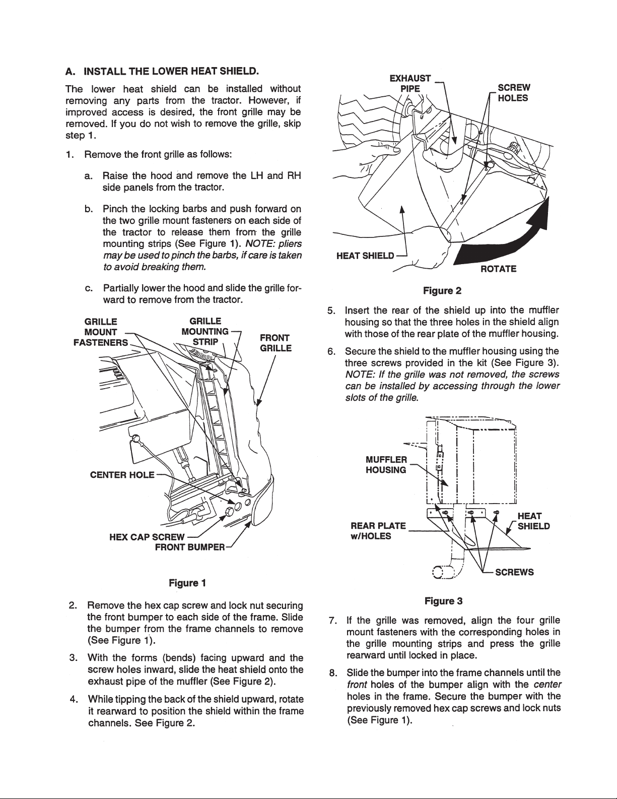
1. Remove both of the hex bolts and lock nuts
securing the front bumper to the frame using a
3/4" socket and a 3/4" wrench.
2. Remove the bumper.
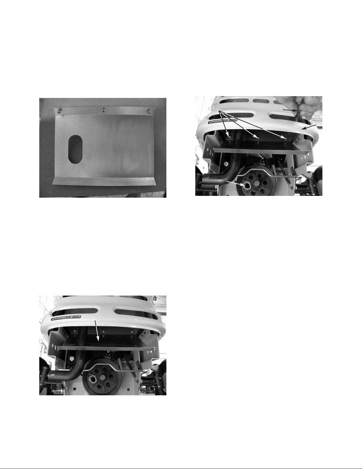
3. Slide the muffler shield over the exhaust pipe and
rotate it into position.
NOTE: Align all three holes in the top of the
muffler shield with the existing shield. Also, the
muffler shield will be slanting towards the bottom
of the front grill assembly.
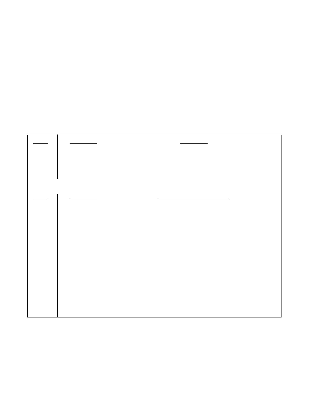
Heat Shield
Heat Shield
HEAT SHIELD
A heat shield has been installed on all 3000 series
tractors for 1999. The heat shield prevents the
exhaust gases from browning the grass. Use kit #759-
3927. See Service Advisory CC-371.
LIFT LINK
The lift link has been modified by strengthening the
powder metal that connects the lift lever to the
hydraulic valve for 1999.
CHECK VALVE
For 1999, a check valve will be installed to the
hydraulic valve to prevent the decks and other attachments from leaking down during and after usage.
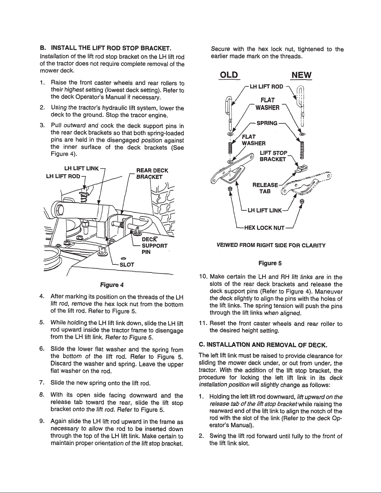
LIFT STOP BRACKET
A lift stop bracket will be installed on the left hand side
of the deck to prevent the deck from hanging up during operations. Use kit #759-3927.
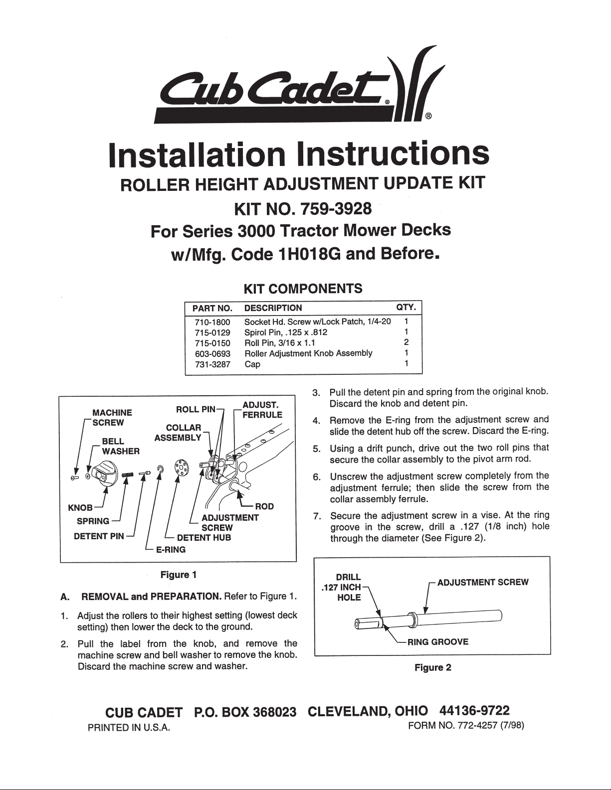
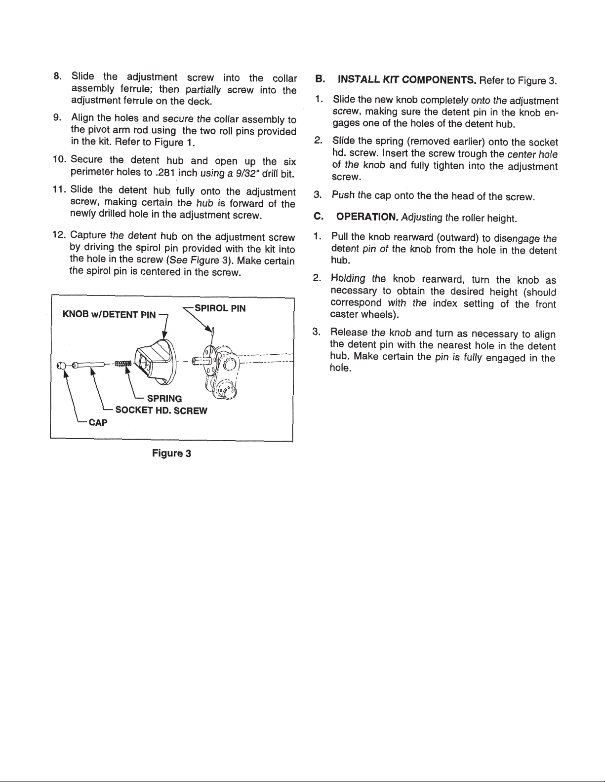
ROLLER HEIGHT ADJUSTER
The rear roller height adjustment mechanism will be
changed for 1999. A newly designed detent pin will
replace the old one, preventing the loss of cutting
height during operations. Use kit #759-3928.
FRONT DECK HANGER ASSEMBLY
The front roller bracket has been redesigned to prevent the front lift rod from detaching during operation.
SEAT IMPROVEMENTS
A safer seat spring, part number 732-0869, can be
installed to level the seat for petite operators. In addition, the seat part number 757-3010A, is now made
out of a softer material for better operator comfort.
See Service Advisory CC-358A Sections 5 and 6.
FRONT MOWER DECK HEIGHT ADJUSTER
The front mower deck height adjuster pins have been
changed from ball detent pins to quick pull pins.
Sheet Metal Screws
Screwdriver
Grill
Mark used in
Production
to Test PTO
Activation
4. Secure the muffler shield with three sheet metal
screws.
NOTE: Use a long flat blade screwdriver through
the air holes in the grill to tighten the sheet metal
screws securely.
5. Install the bumper.
Page 10
2 - 2
Cub Cadet 3000
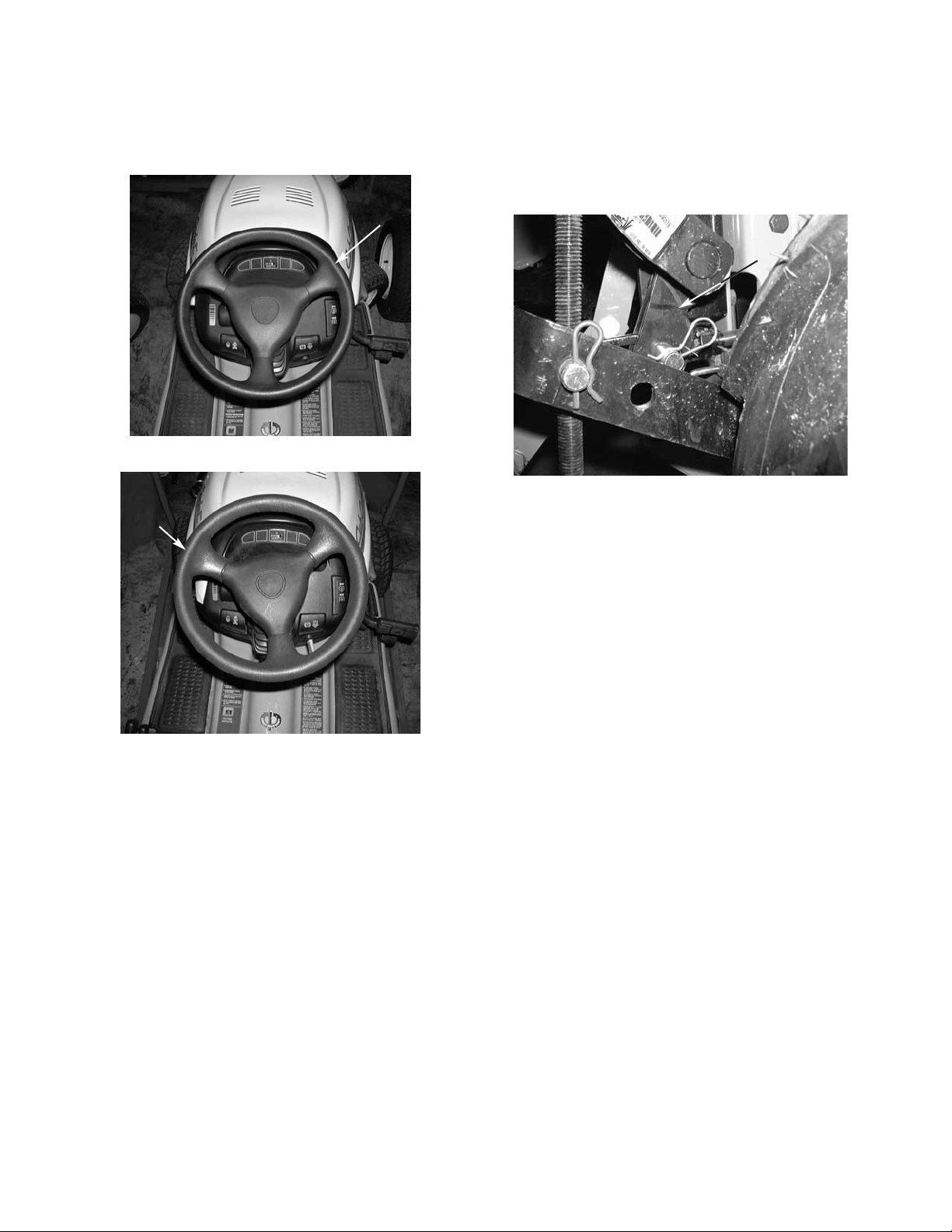
STEERING WHEEL
The thickness of the steering wheel has been
increased for operator comfort.
New Thicker Steering Wheel
Steering
Wheel
Thicker
Old Style Steering Wheel
Steering
Wheel
Thinner
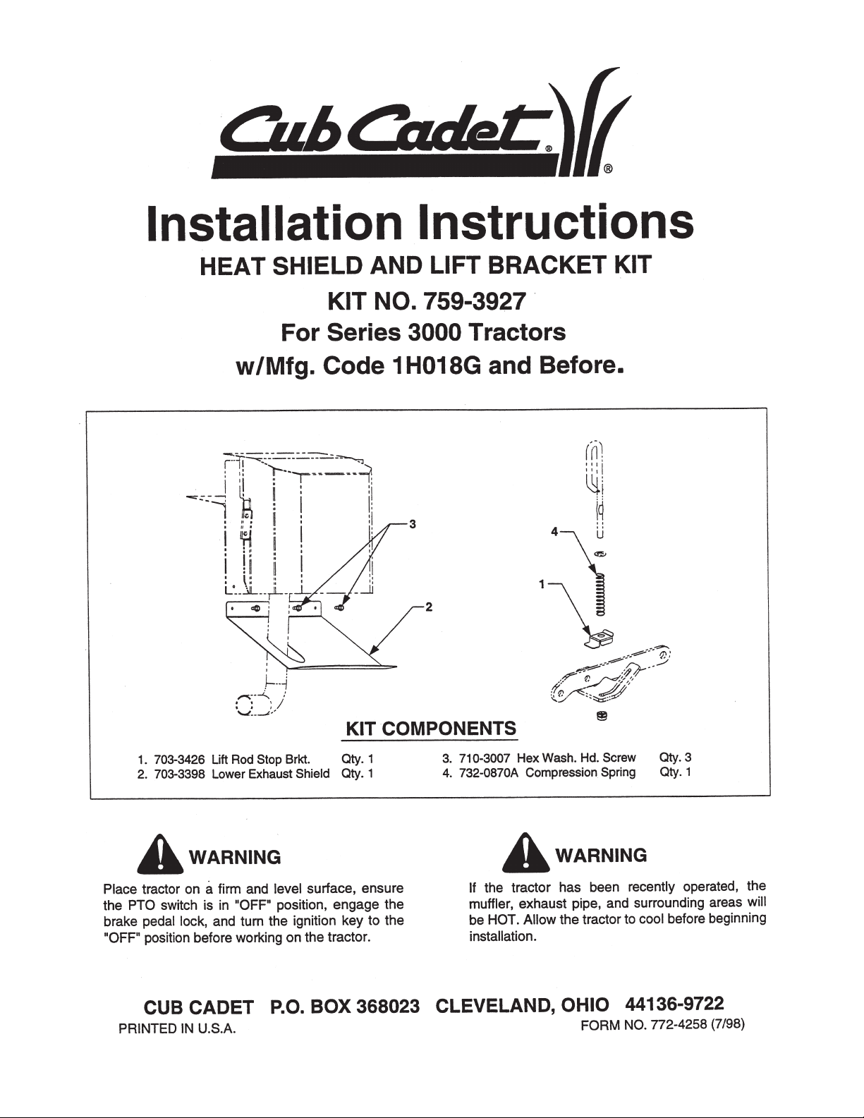
ROCK SHAFT ASSEMBLY FOR 3 POINT HITCH
190-365-100
The cylinder arms have been redesigned with two V
sections cut out to allow for clearance of the clevis nut
on the cylinder shaft. See Service Advisory CC-364.
3000 Series Lift Assembly
Grooved
Out Area
Page 11
2 - 3
Cub Cadet 3000
Page 12
2 - 4
Cub Cadet 3000
Page 13
2 - 5
Cub Cadet 3000
Page 14
2 - 6
Cub Cadet 3000
Page 15
2 - 7
Cub Cadet 3000
Page 16

NOTES
Page 17
3 - 1
Cub Cadet 3000
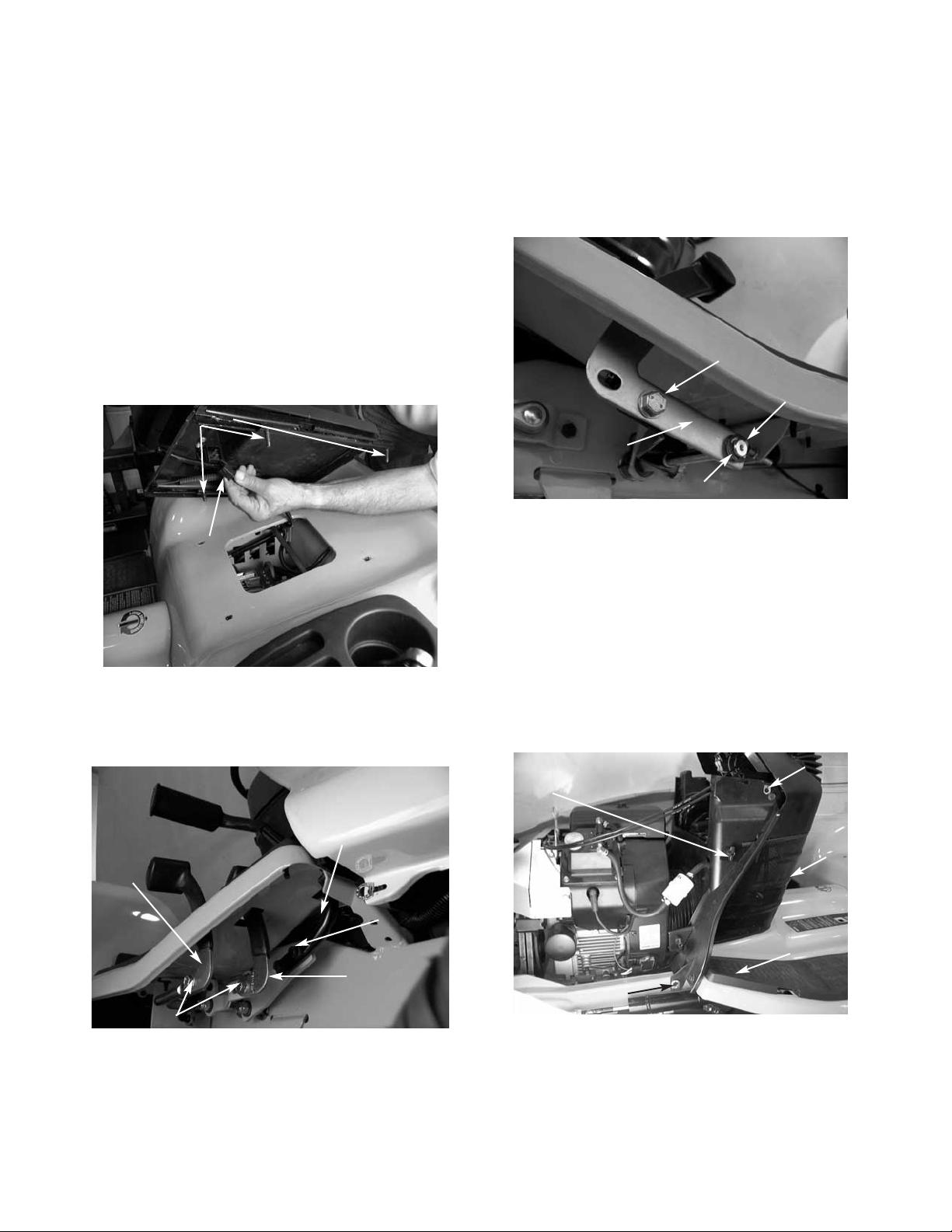
1. Slide the seat back and remove the front two pan
torx head screws using a T30 torx.
2. Slide the seat forward and remove the rear two
pan torx head screws using a T30 torx.
3. Pivot the seat assembly to the side and
disconnect the seat safety switch. See figure 1.
NOTE: Be careful not to scratch the fender with
the seat support brackets. It is advisable to use a
towel or cloth under the seat when pivoting the
seat.
4. Remove the seat from the tractor. See figure 1.
5. Remove all the hex bolts securing the three foot
pedals to the right side of the unit using a 9/16
socket. See figure 2.
Fender Assembly Removal and Reinstallation
FIGURE 1.
Torx Screws
Seat Safety
Switch
FIGURE 2.
Hex Bolts
Hex
Bolts
Reverse
Pedal
Forward
Pedal
Brake
Pedal
FIGURE 3.
Hex Bolt
Differential Lock
Out Pedal
Nylon Flange
Bearing
E-Clip
6. Remove the hex bolt securing the differential lock
out pedal on the left side of the unit using a 9/16
socket. Remove the “E” clip and the nylon flange
bearing from the pivot shaft.
FIGURE 4.
Wing
Nut
Side Panel Latch
Dash
Screen
Side Panel Latch
Rubber Foot Pads
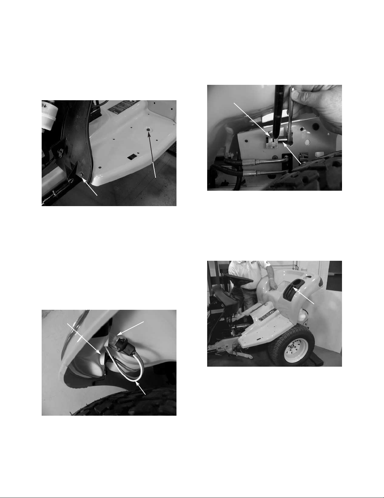
7. Remove both rubber floor pads from the running
boards. See figure 4.
8. Lift the hood and remove the battery cover.
9. Remove both side panels from the tractor by
raising the latches horizontally and turning the
latches 1/4 turn. See figure 4.
10. Loosen all four plastic wing nuts holding the dash
panel screen in place. See figure 4.
11. Pull the dash screen towards the rear of the unit
and out of the dash panel. See figure 4.
Page 18
3 - 2
Cub Cadet 3000
12. Remove all four running board hex bolts from the
tractor using a 1/2” socket. See figure 5.
NOTE: There are two bolts fastening the running
boards to the frame where the foot pads connect
and there are two bolts fastening the running
boards to the dash panel.
FIGURE 5.
Hex Bolt
Hex Bolt
FIGURE 6.
Tail
Light
Reverse
Light
White Wire
for Reverse
13. Remove the fuel cap.
14. Remove the tail light sockets from the tail light
assemblies by pushing in on the sockets gently
and twisting a 1/4 turn. See figure 6.
NOTE: When pulling the sockets out of the tail
light assemblies, it is very important to make sure
the light bulbs come straight out, or the light bulbs
will fall into the tail light assemblies. Also, note
the color of the wires for reinstallation. The white
wires go to the reverse lights. See figure 6.
FIGURE 7.
Hydraulic Lift
Handle Clamp
1/2" Socket
17. Remove the lift handle from the tractor through
the slot in the flap. See figure 8.
NOTE: If the lever is not removed at this time,
damage may occur to the lift knob.
18. Raise and remove the fender assembly.
FIGURE 8.
Slot for
Lift Handle
15. Raise the rear fender high enough to access the
hydraulic lift handle clamp. See figure 7.
16. Loosen the clamp connecting the hydraulic lift
handle to the center lift valve using a 1/2” socket.
19. Reinstall the fuel cap.
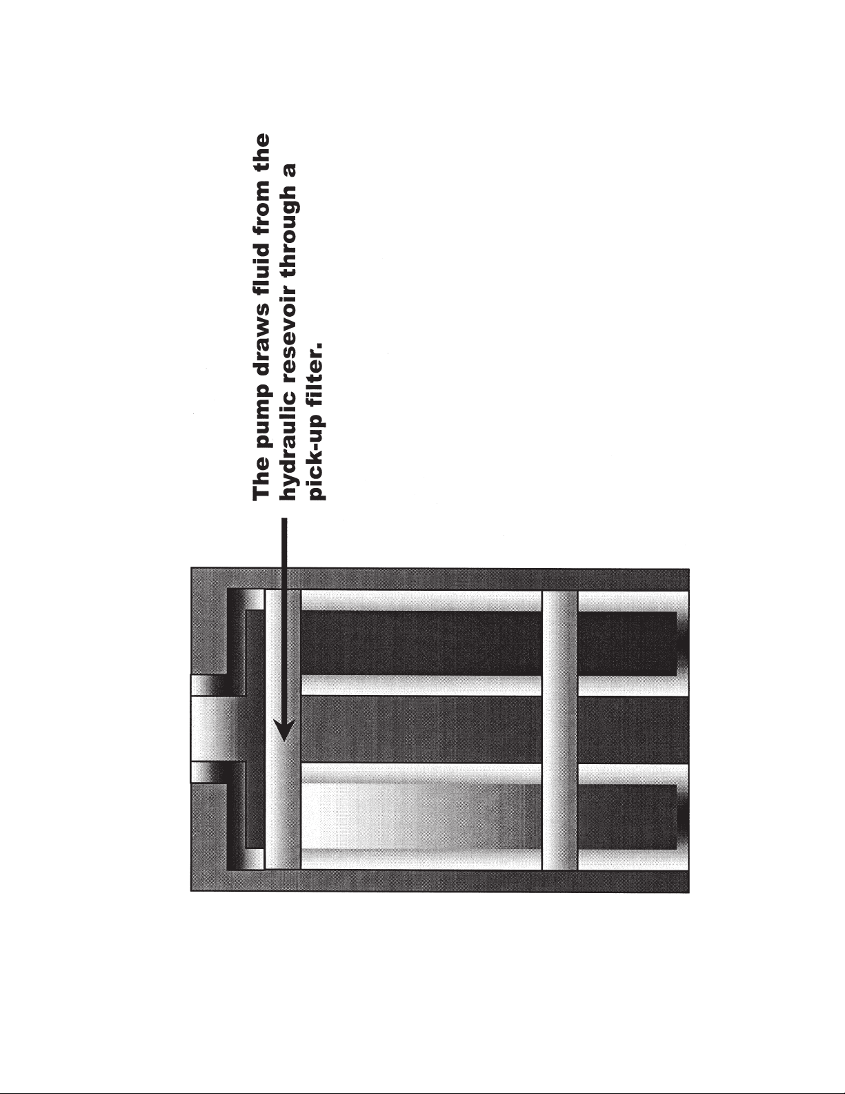
Page 19
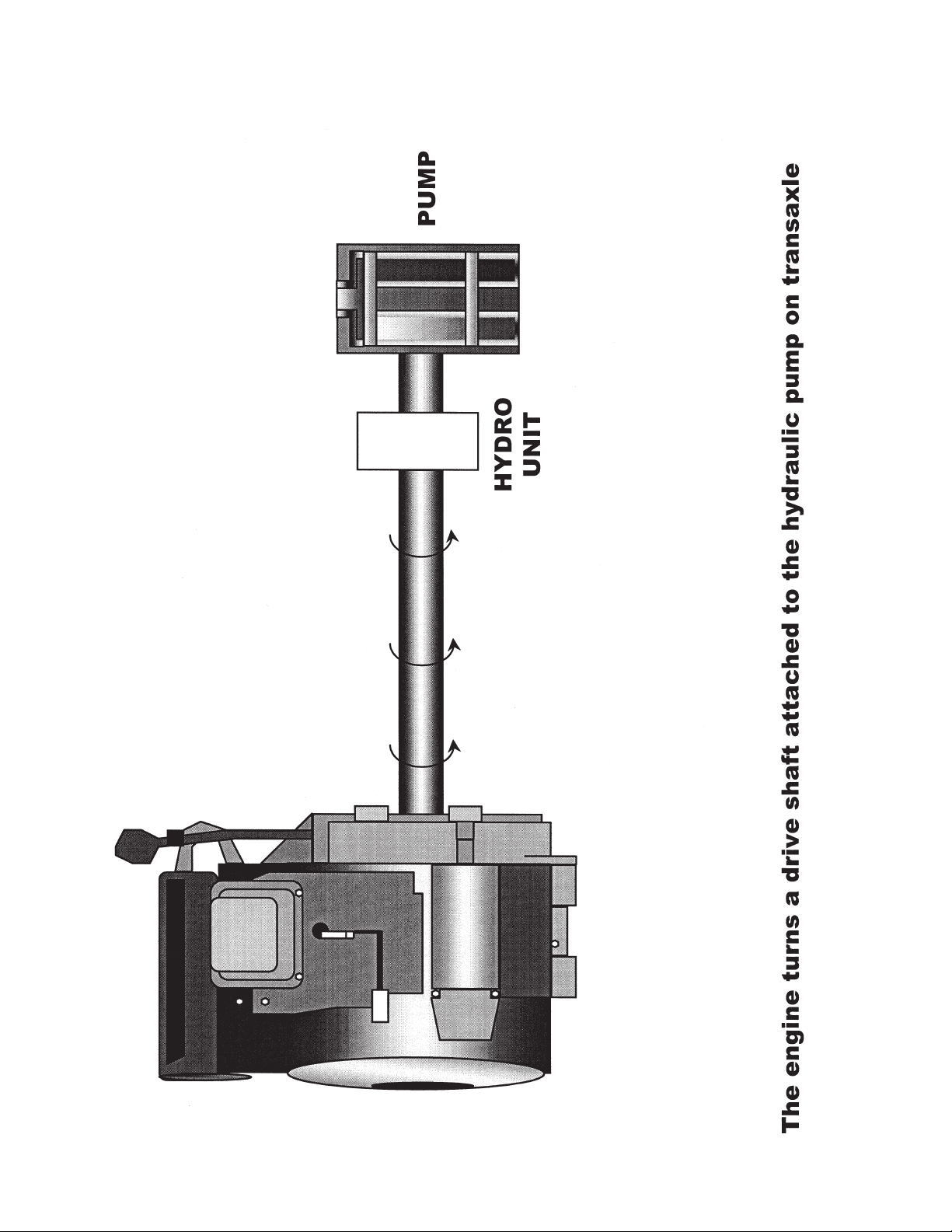
4 - 1
Cub Cadet 3000
Page 20
4 - 2
Cub Cadet 3000
Page 21
4 - 3
Cub Cadet 3000
Page 22

4 - 4
Cub Cadet 3000
Page 23
4 - 5
Cub Cadet 3000
Page 24
4 - 6
Cub Cadet 3000
Page 25
4 - 7
Cub Cadet 3000
Page 26
4 - 8
Cub Cadet 3000
Page 27
4 - 9
Cub Cadet 3000
Page 28
4 - 10
Cub Cadet 3000
Page 29
4 - 11
Cub Cadet 3000
Page 30
4 - 12
Cub Cadet 3000
Page 31

4 - 13
Cub Cadet 3000
Page 32

4 - 14
Cub Cadet 3000
Page 33

5 - 1
Cub Cadet 3000
CAUTION: Slowly remove the hydraulic lines from the
cylinder. Test for pressure in the lines before removal.
1. Place an oil pan directly under the steering
cylinder. This will catch the hydraulic fluid that will
be drained from the lines and the cylinder.
2. Remove both hydraulic line connectors from the
fittings on the cylinder using an 11/16 and a 5/8
open end wrench. See figure 1.
3. Lower the hydraulic lines down into the oil pan
and allow to drain.
4. Remove the front ball joint NUT
from the steering
arm using a 17mm and 3/4" open end wrench.
See figure 2.
NOTE: Remove the ball joint NUT only
!!!
Removal and Replacement of the Power Steering Cylinder
FIGURE 1.
11/16"
5/8"
FIGURE 2.
17mm
Wrench
3/4
Wrench
5. Remove both of the hex head screws and the hex
flange nuts from the cylinder mounting bracket
using a 9/16 socket and a 9/16 wrench. See
figure 3.
FIGURE 3.
Hex Screws
6. Tilt the cylinder down into a pan and allow the oil
to drain.
7. Remove the front ball joint from the steering arm.
8. Remove the flat washer from the top of the
steering arm.
9. Place the cylinder on a bench and remove the
hex nut securing the cylinder to the mounting
bracket using a 17mm wrench and a 3/4" open
end wrench.
10. Slowly push the cylinder rod into the cylinder until
it is fully closed.
NOTE: At this point, the cylinder and both ball
joints are still in the original positions.
11. Record the exact positions of all the ball joints,
hex nuts and fittings on the cylinder. See figure 4.
12. Measure the distance from the inner edge of the
ball joint hex nut to the cylinder end. Repeat this
step for the opposite end. Write both distances
down. See figure 4.
NOTE: The proper measurements are needed to
keep the steering adjusted properly during
reassembly. These measurements should be
approximately 2.75" on the rod end, and 7/16" on
the mounting bracket end. See figure 4.
13. Remove the ball joints and hex nuts from the
cylinder.
Ball
Joint
Cylinder
Mounting
Bracket
Hex
Nut
Fitting
Page 34

5 - 2
Cub Cadet 3000
FIGURE 4.
Cylinder Rod
Ball
Joint
Ball
Joint
Hex
Jam Nut
Hex
Jam Nut
Hex
Jam
Nut
Elbow
Fitting
Elbow
Fitting
Approx.
2.75"
7/16”
90°
45°
“O” Rings
CAUTION ON THE NEXT STEP: There are “O” rings
between the cylinder block and the fittings. Extreme
care should be used to hold the fittings in place while
loosening the hex jam nuts, or damage will occur to
the “O” rings. Replacement of the “O rings” is
recommended.
14. Hold the hydraulic cylinder elbow fittings in place
with a 5/8 wrench, and loosen the hex jam nuts
with an 11/16 wrench. Slowly back the fittings out
of the cylinder.
15. Replace the “O” rings at this point.
NOTE: The front fitting is a 90 degree and the
rear fitting is a 45 degree.
1. Set the new hydraulic steering cylinder on a
bench.
2. Loosen the hydraulic fitting jam nut until it
bottoms out on the threads.
3. Press the flat washer snug up against the hex
jam nut.
4. Inspect the “O” ring for damage. If damaged,
replace.
5. Press the “O” ring snug up against the flat
washer.
6. Gently screw the fitting into place until the fitting
becomes snug.
NOTE: Do not tighten!!! At this time the “O” ring
will be seated properly in the cylinder port. If it is
over tightened, damage will occur.
Reinstallation of the Hydraulic Fittings to the Cylinder
7. Slowly unscrew the hydraulic fitting to the correct
recorded position.
NOTE: Do not unscrew the fitting more than one
full turn, because the cylinder may leak at the “O”
ring.
8. Hold the fitting in place with a 5/8 wrench, and
tighten the hex nut with an 11/16 wrench.
INSTALL THE SECOND FITTING BY REPEATING
STEPS ONE THROUGH EIGHT IN THIS SECTION.
Page 35

6 - 1
Cub Cadet 3000
Cub Cadet 3000 Series Char-Lynn 2 Series
Steering Control
Figure 1.
The following information may be used in the inspection and repair of Eaton’s Char-Lynn 2 series steering
control units.
Tools required for disassembly and reassembly: 10
mm socket, 7/8 in. socket, ratchet wrench, torque
wrench (160 lb. in. capacity)
Tool List
• 10 mm Socket
• 7/8 in Socket
• Torque Wrench (160 lb-in Capacity)
• Small Blade Screwdriver
The following disassembly procedures may be used
to disassemble the 2 series steering control. The configuration of your steering control may vary from the
pictures shown in this program. The configuration of
each control is determined by model. Different models
may incorporate different component parts and/or
assemblies. These differences may be the width of
the gerotor assembly, spool/sleeve assembly, housing configuration and etc.
When ordering replacement parts, give the product
number and date code. The product and date code is
noted on the serial number tag, which is located on
the side of the valve housing.
It is recommended that the steering control be thoroughly cleaned before any repairs are attempted.
When cleaning, be sure all open ports are sealed.
Figure 2.
To disassemble the steering control, first support the
control in a vertical position with the metering (gerotor) section end up. Using a 10 mm socket wrench,
remove the metering section end cap retaining cap
screws.
NOTE: When using a bench vise to support the control, caution must be used not to use excessive
clamping pressure on the control housing that could
cause housing distortion.
Figure 3.
Page 36

6 - 2
Cub Cadet 3000
Figure 4.
Remove the end cap from the gerotor assembly.
Figure 7.
Figure 6.
Figure 5.
Remove the o-ring seal from the gerotor assemblies
outer ring.
Remove the gerotor assemblies outer ring.
NOTE: The gerotor assembly may/may not remain
intact during removal.
Remove both the seal ring and o-ring seal from the
gerotors inner star.
Page 37

6 - 3
Cub Cadet 3000
Figure 8.
Remove the gerotors inner star from the drive.
Remove the wear plate from the housing assembly.
Remove the o-ring seal from the wear plate.
Remove the drive from the spool/sleeve assembly.
Remove the spacer.
Figure 11.
Figure 10.
Figure 9.
Figure 13.
Figure 12.
Remove the o-ring from the control housing.
Page 38

6 - 4
Cub Cadet 3000
The spool/sleeve assembly may be removed from the
control valve housing in either the vertical or horizontal position.
VERTICAL POSITION
Carefully reposition the control valve assembly in the
vertical position with the meter end of the control
valve housing pointing upward. Remove the
spool/sleeve assembly from the control valve housing.
IMPORTANT: Do not bind the spool/sleeve assembly
in the control housing.
Rotate the spool/sleeve assembly slightly and slowly
when removing from the control housing.
HORIZONTAL POSITION
Rotate the spool/sleeve assembly until the cross pin
is horizontal with the porting face flange. Position the
control valve assembly with the porting face on a
clean flat surface.
Remove the spool/sleeve assembly from the metering
section end of the control housing keeping the cross
pin in the horizontal position.
IMPORTANT: Do not bind the spool/sleeve assembly
in the control housing.
Rotate the spool/sleeve assembly slightly back and
forth when removing from the control housing.
Figure 16.
Figure 15.
Figure 14.
Push or pull the spool forward to remove it from the
sleeve.
NOTE: Caution must be used not to dislodge the
spring retaining ring during removal of the spool from
the sleeve.
Using a small screwdriver or similar type tool, remove
the cross pin from the spool/sleeve assembly.
Page 39

6 - 5
Cub Cadet 3000
Figure 20.
Figure 19.
Figure 18.
Figure 17.
Using the small screwdriver or similar tool, remove the
dust seal. Caution must be used not to scratch or
damage the dust seals counter bore when removing
the dust seal.
Turn the valve housing over and remove the two
bearing races and thrust bearing.
Carefully remove the centering springs from the
spool.
NOTE: It is not necessary nor recommended to
remove the external ring from the spool.
Carefully remove the spring retaining ring from the
centering springs.
Page 40

6 - 6
Cub Cadet 3000
Again using a small screwdriver or similar tool,
remove the quad ring seal from the valve housing.
REASSEMBLY
Prior to the reassembly of the steering control,
replace all worn and damaged parts and/or
assemblies along with all seals and sealing rings.
Clean all parts in clean solvent and blow dry with
compressed air.
Lubricate all finished parts surfaces freely with clean
hydraulic fluid during assembly to provide instant
lubrication between rotating surfaces at start-up.
Lubricate all seals and sealing rings with petroleum
jelly to help retain the sealing rings during reassembly
and provide lubrication to the dust and spool seals.
Install the two bearing races and thrust bearing into
the valve housing.
Shown here are both the relief valve check and check
ball assemblies.
The relief valve check assembly is optional.
Using a 7/8 in. socket or end wrench, remove the
relief valve check or check ball plug.
Figure 23.
Figure 22.
Figure 21.
Figure 24.
Page 41

6 - 7
Cub Cadet 3000
After the seal is installed, turn the valve housing over
and remove the sleeve, races and bearing.
Using caution to retain the races, bearing and sleeve
in the valve housing, carefully turn the assembly over
and set it on a clean flat surface. Together, the housing, races, bearing and sleeve create a groove into
which the quad seal can be installed. Lubricate and
install the quad seal in its seat through the input end
of the valve housing.
CAUTION: When installing, be sure the quad seal is
not twisted.
Install the sleeve into the valve housing.
Figure 27.
Figure 26.
Figure 25.
Turn the valve housing over and press the dust seal
into its bore, located in the face of the valve housing.
NOTE: The lip of the dust seal must point away from
the valve housing.
Figure 28.
Page 42

6 - 8
Cub Cadet 3000
Next install one set of the 3 curved centering springs
between the two flat pieces.
To install the centering springs on the spool, first
install the two flat pieces.
Shown here is the correct orientation of the
spool/sleeve centering springs. Two sets of (3) each
curved springs in the center and (1) each flat piece on
the outside.
Figure 31.
Figure 30.
Figure 29.
Figure 32.
Then install the final set of 3 curved centering springs
between the flat piece and the previously installed
curved centering springs.
NOTE: The bowed side of the two sets of 3 centering
springs must point toward each other.
Page 43

6 - 9
Cub Cadet 3000
Push the spool assembly into the sleeve until the centering springs are firmly positioned into the notches
located in the sleeve.
Lubricate the spool assembly and install into the
sleeve, aligning the centering springs with the notches
machined in the sleeve.
Center the centering springs and install the spring
retaining ring over the springs.
Figure 35.
Figure 34.
Figure 33.
Figure 36.
Insert the cross pin into the spool/sleeve assembly.
Page 44

6 - 10
Cub Cadet 3000
Lubricate and install the o-ring seal into the groove
located in the control valve housing.
Lubricate and install the spool/sleeve assembly into
the valve housing.
Supporting the valve housing in the upright position,
lubricate and install the bearing races and thrust bearing.
NOTE: The thrust bearing must be installed between
the two bearing races.
Figure 39.
Figure 38.
Figure 37.
Figure 40
Install the wear plate by aligning the holes in the wear
plate with the cap screw and porting holes in the control housing.
NOTE: The grooved side of the wear plate must point
upward.
Page 45

6 - 11
Cub Cadet 3000
Lubricate and install both the gerotor star and outer
ring. Install by aligning the splines of the star with the
drive. After installation, rotate the gerotors outer ring
to align with the housing cap screw holes.
NOTE: The grooved side of both gerotor star and
outer ring must face upward.
Install the drive, making sure you fully engage the slot
on end of drive with the cross pin in the spool/sleeve
assembly.
Lubricate and install the o-ring seal into the groove
located in the wear plate.
Figure 43.
Figure 42.
Figure 41.
Install drive spacer in gerotor star.
Figure 44.
Page 46

6 - 12
Cub Cadet 3000
Prior to the installation of the end cap, freely lubricate
the gerotor star seal ring.
Lubricate and install the o-ring seal into the groove
located in the gerotors outer ring.
Lubricate and install both the o-ring seal and seal ring
into the gerotor star. Install the o-ring in the groove
located in the star first and then the seal ring.
Figure 47.
Figure 46.
Figure 45.
Figure 48.
Install the end cap onto the gerotor assembly by
aligning the cap screw holes.
Page 47

6 - 13
Cub Cadet 3000
The steering control is now ready for test and installation.
Torque plug to 15 in. lbs.
Install the check ball or optional relief valve check as
shown here.
Install the end cap retaining cap screw and tighten in
a crisscross sequence. Torque to 140-160 in. lbs.
Figure 52.
Figure 51.
Figure 50.
Figure 49.
Page 48

6 - 14
Cub Cadet 3000
Page 49

6 - 15
Cub Cadet 3000
Page 50

6 - 16
Cub Cadet 3000
Page 51

6 - 17
Cub Cadet 3000
Page 52

NOTES
Page 53

7 - 1
Cub Cadet 3000
CAUTION: Slowly remove the hydraulic lines from the
cylinder. Test for pressure in the lines before removal.
1. Place an oil pan directly under the center lift
cylinder. This will catch the hydraulic fluid that will
be drained from the lines and the cylinder.
2. Remove the hairpin from the clevis pin at the rear
of the lift cylinder. See figure 1.
3. Slide the clevis pin all the way to the left rear tire.
4. Pull the cylinder towards the center of the
machine and release the cylinder from the clevis
pin. See figure 2.
5. Pull the cylinder forward applying pressure to the
lift shaft assembly. The lift shaft assembly will
pivot forward with the cylinder, and allow the rear
of the cylinder to pass by the front transmission
support bracket.
Removal and Replacement for the Center Lift Cylinder
FIGURE 1.
Lift
Cylinder
Hairpin
Clevis Pin
FIGURE 2.
Lift Shaft
Assembly
Front Transmission
Support Brkt.
6. Remove both hydraulic connectors from the lift
cylinder using a 7/8” open end wrench.
NOTE: The front connector on the lift cylinder
hydraulic line runs to the top port of the lift valve.
The back connector on the lift cylinder hydraulic
line runs to the bottom port of the lift valve. Be
sure to reinstall the hydraulic lines in the correct
ports during reassembly.
7. Inspect the “O” rings on the connectors for any
damage. If damaged, replace.
8. Pivot the cylinder down 90 degrees and release
the slotted bracket from the lift shaft assembly
cam. See figure 3.
NOTE: Allow the hydraulic fluid to drain
completely from the cylinder into the oil pan.
FIGURE 3.
Hydraulic Connectors
Slotted
Bracket
Clevis Pin
Hole
Lift Shaft
Assembly
Cam
REINSTALL THE CENTER LIFT CYLINDER IN THE
REVERSE ORDER ABOVE.
NOTE: When reinstalling the cylinder to the cam on
the lift shaft assembly, make sure the slotted cylinder
bracket is offset towards the left frame of the tractor.
Clevis
Pin
Page 54

NOTES
Page 55

8 - 1
Cub Cadet 3000
Prior to removing the pump adapter, it is necessary to
remove the fender assembly.
1. Remove the side panels and disconnect the
spark plug wires.
2. Remove all four of the hex head tapp screws that
connect the drive shaft to the pump adapter using
a 3/8 socket. See figure 1.
3. Remove both hex cap screws and lock nuts from
the tilt wheel coupling using a 7/16 wrench and a
7/16 socket. See figure 2.
Removal and Replacement of the Pump Adapter
FIGURE 1.
Pump
Adapter
Tap
Screws
Tap
Screw
Drive
Shaft
FIGURE 2.
Upper
Steering Shaft
Tilt Wheel
Coupling
Hex Cap
Screws
4. Raise the upper steering shaft. See figure 3.
5. Remove the lower steering shaft from the
hydraulic steering pump. See figure 3.
FIGURE 3.
Bottom
Coupling
Half
Drive
Shaft
Sleeve
Bearing
Lower
Steering
Shaft
6. Slide the drive shaft towards the left frame rail.
NOTE: Be careful not to dislodge the blue barrels
on each end of the drive shaft.
7. Remove the fan from the pump adapter and set it
aside.
NOTE: There may be a spacer on the coupler. If
so, set it aside.
8. Loosen the nut securing the pump adapter using
a 9/16 socket. See figure 4.
NOTE: Channel locks may be needed to hold the
pump adapter in place while breaking the pump
adapter nut free.
FIGURE 4.
Page 56

8 - 2
Cub Cadet 3000
9. Finger loosen the pump adapter nut until it is
flush with the end of the hydro input shaft.
10. Place a 13/16 socket against the nut with the
opened end of the socket facing away from the
nut. See figure 6.
11. Place the new pump adapter, cupped side in,
over the opened end of the 13/16 socket. See
figure 5.
12. Finger tighten two of the drive shaft hex screws
across from one another.
13. Using a 3/8 socket, tighten the hex screws
equally a quarter of a turn at a time until the old
hub breaks free. See figure 5.
FIGURE 5.
13/16
Socket
Drive Shaft
Hex Screw
Original Pump
Adapter
New Pump
Adapter
14. Remove the hex screws and new hub. See
figure 5.
15. Remove the hex nut, bell-washer, old pump
adapter, and key from the input shaft.
FIGURE 6.
13/16
Socket
Bell-
Washer
Hex Nut
Drive Shaft
Hex Screws
Original
Pump
Adapter
New Pump
Adapter
INSTALLATION OF THE NEW PUMP ADAPTER
1. Clean the hydrostatic input shaft of any debris.
See figure 7.
2. Apply a light coat of loctite 803 to the taper of the
input shaft. See figure 7.
3. Place the new fan over the cone of the new pump
adapter.
4. Push the new pump adapter and fan onto the
hydro input shaft.
NOTE: The fan will be on the inside of the pump
adapter.
FIGURE 7.
Loctite
Input
Shaft
Fan
5. Install the new bell washer and locknut.
NOTE: Hold the new pump adapter in place with
a drift punch and torque the lock nut to 20 ft. lbs.
See figure 8.
FIGURE 8.
Torque
Wrench
Drift
Punch
Page 57

8 - 3
Cub Cadet 3000
6. Line up the drive shaft with the new pump
adapter.
NOTE: If there is more than an 1/8” gap between
the drive shaft and pump adapter place the
spacer in between the the drive shaft and the
pump adapter. Do not force the spacer in if it
does not fit.
7. Install the new bolts through the drive shaft, pump
adapter, and the fan.
8. Finger tighten the shoulder nuts with the shoulder
facing the fan.
NOTE: The shoulder on the nuts fit into the fan
holes. See figure 9.
FIGURE 9.
Shoulder Nut
Shoulder Nuts
FIGURE 10.
7/16
Bolts
9. Tighten the hex bolts and shoulder nuts securing
the pump adapter assembly, using a 7/16 wrench
and a 7/16 socket. See figure 10.
REINSTALL THE FENDER ASSEMBLY.
Page 58

NOTES
Page 59

9 - 1
Cub Cadet 3000
Prior to performing this test, it is necessary to remove
the deck and fender assemblies.
1. Remove the hex cap screw securing the double
valve clamp to the charge pump using an 11mm
swivel socket. See figure 1.
2. Remove the hydraulic pressure tube end from the
charge pump.
BDU-21L-500 Auxiliary Pressure Test
FIGURE 1.
Hydraulic
Return Tube
Pressure
Tube
Hex
Bolt
Double
Valve
Clamp
6. Install the pressure test kit into the unit with the
pressure gauge standing straight up. See figure 3
and 4.
7. Reinstall the double valve clamp to the charge
pump. See figure 1.
8. Reinstall the power steering pump port plate. See
figure 2.
9. Fasten all hardware securely.
FIGURE 3.
Pressure Gauge
To Steering Pump
To Charge Pump
FIGURE 2.
Pressure Tube
Charge Pump to
Steering Pump
Steering Pump to Rear
of Steering Cylinder
Return
Tube to
Charge
Pump
Port Plate
From Steering
Pump to
Auxiliary
Valve
Steering Pump
to Front of
Steering
Cylinder
Hex Cap
Screw
Hex Cap
Screw
3. Remove both of the hex cap screws from the
power steering pump port plate using a 13mm
wrench. See figure 2.
4. Remove the hydraulic pressure tube end from the
hydraulic steering pump. Charge pump to steering pump. See figure 2.
NOTE: Be careful not to damage the “O” rings. If
damaged, replace.
5. Remove the hydraulic pressure tube from the
unit.
10. Start the unit and allow the hydraulic fluid to
circulate at idle.
11. Slowly increase the throttle to full.
12. Slowly decrease the throttle to idle. Record the
hydro reading at the pressure gauge. See
figure 4.
NOTE: The pressure will be very low if shown at all
on the gauge.
FIGURE 4.
Page 60

9 - 2
Cub Cadet 3000
13. Increase the throttle to full. Record the hydro
reading at the pressure gauge. The reading
should be between 200 PSI and 650 PSI. See
figure 5.
NOTE: This system should not read higher than 650
PSI. The relief valve is set to 650 PSI in the auxiliary
manifold.
FIGURE 5.
FIGURE 6.
14. Remain at full throttle and max out the lift valve.
There should be a PEAK pressure of 1100-1200
PSI. See figure 6.
NOTE: Only hold the lift valve for a short amount
of time. Record the reading and release the lift
valve lever as quick as possible.
IMPORTANT:
System pressure will increase with the
actuation of the power steering and/or deck lift.
If the pressure readings are not
meeting the specifica-
tions, the charge pump is faulty.
If the pressure readings are meeting specifications,
the charge pump is not faulty and the mechanical
system must be checked.
Page 61

9 - 3
Cub Cadet 3000
Bill of Materials
• 2 - 3000 P.S.I. Hydraulic Gauges
• 1 - 200 P.S.I Hydraulic Gauge
• 2 - 9/16-18 Straight Thread O-ring & JIC fitting (JIC
dependent on hose fittings)
• 3 - 3000 P.S.I. hoses of adequate lengths
(Connect as shown in FIG 1)
• 1 - T fitting
• 1 - needle valve
Connection Procedure
1. Remove tractor seat.
2. Remove both check plugs using a 1/4” hex drive.
3. Replace check plugs with the 2 9/16-18 straight
thread O-ring fittings.
4. Connect the T fitting and needle valve to the left
side. (Reverse Hi)
• Connect the 200 P.S.I. gauge to the needle
valve making sure flow can be shut off to this
gauge.
• Connect the 3000 P.S.I. gauge to the T fitting.
5. Connect another 3000 P.S.I. fitting to the right
side. (Forward high pressure port)
Hydrostatic Transmission Pressure Test Setup
FIGURE 1.
Forward ONLY Test Procedure
1. Lift tractor elevating rear tires off the ground.
(Tires will rotate)
2. Remove pin from parking brake. (allowing brake
to be apply while not in neutral)
3. Open needle valve allowing flow to the 200 P.S.I.
gauge (applying reverse can now damage this
gauge).
Charge Pressure Gauge
Forward
High
Pressure
Gauge
Reverse High
Pressure Gauge
4. With tractor running, apply parking brake.
5. Continue holding the brake. depress the forward
foot pedal until max. pressure is seen on right
side gauge.
6. Record pressures from the 200 P.S.I. gauge and
the right side 3000 P.S.I. gauge.
Reverse ONLY Test Procedure
** To test for reverse side high pressure switch the
changes to opposite ports and repeat the similar to
the forward test. **
Conclusion
The 200 P.S.I. gauge sees the charge pressure in the
system, and during this type of the test the pressure
should be 20-40 P.S.I. The right side 3000 P.S.I.
gauge sees the forward high pressure and for this test
should read 1000 to 1400 P.S.I. If the gauges see
values close to this range the hydrostat is functioning
properly.
Page 62

NOTES
Page 63

10 - 1
Cub Cadet 3000
Prior to removing the steering pump, it is necessary to
remove the fender assembly.
CAUTION:
Slowly remove the hydraulic lines from the
hydraulic steering pump. Test for pressure in the lines
before removal.
1. Place an oil pan directly under the hydraulic
steering pump. This will catch the hydraulic fluid
that will be drained from the lines and the pump.
2. Remove all four of the hex head tapp screws from
the drive shaft to the pump adapter using a 3/8
socket.
NOTE: Removal of the drive shaft from the pump
adapter is necessary to allow access to the four
hydraulic steering pump mounting bolts.
Removal and Replacement of the Hydraulic Steering Pump
3. Remove both hex cap screws and lock nuts from
the tilt wheel coupling using a 7/16 wrench and a
7/16 socket. See figure 2.
FIGURE 1.
Pump
Adapter
Tap
Screws
Tap
Screw
Drive
Shaft
FIGURE 2.
Upper
Steering Shaft
Tilt Wheel
Coupling
Hex Cap
Screws
4. Raise the upper steering shaft. See figure 3.
5. Remove the lower steering shaft from the
hydraulic steering pump. See figure 3.
NOTE: The lower steering shaft is splined on
each end and requires lubrication prior to
reassembly.
6. Slide the drive shaft towards the left frame rail.
NOTE: Be careful not to dislodge the blue barrels
on each end of the drive shaft.
FIGURE 3.
Bottom
Coupling
Half
Drive
Shaft
Sleeve
Bearing
Lower
Steering
Shaft
7. Write down the exact locations of all the hydraulic
tubes. See figure 4.
8. Remove both hex cap screws from the steering
pump port plate using a 13mm wrench.
9. Remove the port plate from the hydraulic lines.
NOTE: Pivot the top edge of the port plate
backward (towards the left frame rail), bringing
the plate to horizontal. Push the port plate up and
rotate the port plate counter-clockwise 90
degrees using the main pressure line as the pivot
point. Slide the port plate towards the left frame
rail until the port plate clears the hydraulic lines.
Upper
Steering
Shaft
FIGURE 4.
Charge Pump to
Steering Pump
Steering Pump to Rear
of Steering Cylinder
Steering
Pump to
Charge
Pump
Port Plate
From Steering
Pump to
Auxiliary
Valve
Steering Pump
to Front of
Steering
Cylinder
Page 64

10 - 2
Cub Cadet 3000
10. Remove the hydraulic tubes from the hydraulic
steering pump.
NOTE: If the hydraulic tubes do not want to come
out, use a small mallet and tap them out of the
ports. Be careful not to damage the tubes.
11. Inspect the “O” rings on the connectors for
damage. If damaged, replace.
NOTE: Place a small amount of grease on the
“O” rings and cover the connector surface
completely for reinstallation.
FIGURE 5.
“O” Rings
12. Support the hydraulic steering pump from below.
See figure 6.
13. Remove the four hex cap screws securing the
hydraulic steering pump to the frame using a
10mm wrench. See figure 6.
FIGURE 6.
Hex Cap
Screws
Steering
Pump
FIGURE 7.
Return
Auxiliary
Steering
Steering
Main Pressure
Refer to the 1998 Cub Cadet Technical Update
Seminar manual for inspection and repair of the CharLynn 2 series Steering Control in Section 17.
REASSEMBLE THE HYDRAULIC STEERING PUMP
IN THE REVERSE ORDER.
14. Remove the hydraulic steering pump from the
tractor.
Page 65

11 - 1
Cub Cadet 3000
Prior to removing the hydraulic valve, it is necessary
to remove the fender assembly.
CAUTION: Slowly remove the hydraulic lines from the
hydraulic valve. Test for pressure in the lines before
removal.
1. Place an oil pan directly under the hydraulic
valve. This will catch the hydraulic fluid that
drains from the lines and the valve.
2. Remove the double valve clamp from the valve
body using a 7/16 socket. See figure 1.
3. Remove both hydraulic hose connectors coming
from the hydraulic lift cylinder to the valve body.
See figure 1.
Removal and Replacement of the Hydraulic Valve
FIGURE 1.
Hydraulic Hose
Connectors
Double Valve
Clamp
Squared
Lift Link
Hex Cap Screws
and Lock Nut
Hex Cap
Screws and
Lock Nut
4. Remove the side valve clamp that holds the
return tube to the valve body. See figure 2.
5. Remove the hydraulic return tube from the “T”
fitting with an 18mm wrench. See figure 2.
6. Remove the hydraulic return tube from the
hydraulic valve body. See figure 2.
FIGURE 2.
T Fitting
Side Valve
Clamp
Valve Body
Hydraulic
Return
Tube
7. Remove the side valve clamp that holds the inlet
tube to the valve body using a 7/16 socket. See
figure 3.
NOTE: All the hydraulic lines and tubes going into
the hydraulic valve ports have two “O” rings on
each connector. See figure 4.
FIGURE 3.
Clamp
Hex Cap Screws
and Lock Nuts
Inlet
Tube
8. Remove both hex cap screws and hex flange lock
nuts securing the hydraulic valve to the frame
using a 7/16 socket. See figure 1.
NOTE: The hydraulic valve body must be
secured to the frame with both screws before the
hydraulic tubes can be assembled to the
hydraulic valve during reassembly.
9. Pull the hydraulic valve body away from the
hydraulic inlet tube slowly.
NOTE: If the hydraulic tube does not want to
come out, use a small mallet and tap it out of the
port. Be careful not to damage the valve body or
the hydraulic tube/s.
10. Remove the valve body from the tractor. See
figure 5.
NOTE: Record the correct positions of the nylon
flange bearings on the squared lift link. See
figure 3.
Nylon Flange
Bearing
Page 66

11 - 2
Cub Cadet 3000
FIGURE 4.
“O” Rings
11. Inspect the “O” rings for damage. If damaged,
replace. See figure 4.
12. Remove all the remaining hardware from the
valve body using a 7/16 socket.
FIGURE 5.
Valve Mounting
Bracket
Nylon Flange
Bearing
Squared
Lift Link
Valve
Mounting
Bracket
Hydraulic
Valve
13. Remove the valve mounting brackets. See
figure 5.
NOTE: Write down the correct positions of the
mounting brackets. The brackets can be installed
backwards if not properly marked.
14. Remove the squared lift link.
REASSEMBLE THE HYDRAULIC VALVE IN THE
REVERSE ORDER ABOVE.
Page 67

12 - 1
Cub Cadet 3000
IMPORTANT: Use proper safety procedures when
working on the tractor.
1. Open the hood and remove the battery box cover.
2. Remove the negative and positive battery
terminal connectors from the battery using a 5/16
socket.
3. Remove both of the side panels from the tractor
by raising the latches horizontally and turning the
latches 1/4 turn. See figure 1.
4. Loosen all four plastic wing nuts holding the dash
panel screen in place.
5. Remove the dash panel screen by pulling it
towards the seat.
6. Cut the cable ties securing the headlight wiring
harness to the hood assembly. See figure 2.
7. Remove the headlight bayonet mounts from both
of the headlights by twisting the sockets 1/4 turn
and pulling straight out. See figure 2.
Engine Removal and Replacement
FIGURE 1.
FIGURE 2.
Headlight
Bayonet Mount
Headlight
Bayonet Mount
Hood
Assembly
Headlight
Wiring
Harness
Cable Tie
8. Partially close the hood to allow access to the grill
fasteners. See figure 3.
9. Squeeze all four grill fasteners and release the
grill. See figure 3.
10. Remove the grill and set it aside.
11. Remove all four hood mounting bolts from the
muffler assembly brackets using a 1/2” socket.
See figure 3.
FIGURE 3.
Grill
Hood Mounting
Bolts
12. Remove all four muffler assembly bracket bolts
from the tractor frame using a 1/2” socket. See
figure 4.
13. Remove the muffler assembly from the engine.
NOTE: Move the muffler assembly side to side.
This will allow the muffler to separate from the
exhaust manifolds. See figure 4.
FIGURE 4.
Muffler
Assembly
Bracket
Bolts
Grill
Fastener
Page 68

12 - 2
Cub Cadet 3000
14. Remove both the choke and the throttle cables.
See figure 5.
NOTE: use a marker and mark the holes and
cable alignment before removal.
FIGURE 5.
Throttle
Choke
15. Disconnect the vacuum tube from the E-Vac
check valve. See figure 6.
FIGURE 6.
E-Vac Check
Valve
16. Disconnect the wiring harness, ground cables,
and any sensor connectors from the engine. See
figure 7.
NOTE: Visually inspect the engine from all angles
to make sure all wires and cables are
disconnected from the engine to the frame.
FIGURE 7.
17. Remove the fuel line from the engine.
NOTE: Make sure the fuel line is fully drained and
secured in a safe place during engine removal.
18. Remove both of the hex bolts securing the belt
guard to the engine using a 13mm socket and
extension. See figure 8.
19. Remove the E-vac clip. See figure 8.
NOTE: Push up on the locking clip and slide the
pin away from the engagement arm.
FIGURE 8.
Hex Bolts
Belt
Guard
E-Vac
Clip
20. Remove the battery from the unit.
NOTE: The battery was removed to give direct
access to the drive shaft bolts through the dash
panel area.
Spark Plug
Boot and Wire
Ground to
Heat Shield
Solenoid
Positive
“Hot”
Lead Wire
Starter
E-Vac
Connector
Page 69

12 - 3
Cub Cadet 3000
21. Remove all four of the hex bolts securing the
drive shaft to the engine flywheel using a 7/16
socket and extension. See figure 9.
FIGURE 9.
Hex Bolts
Drive
Shaft
FIGURE 10.
Engine
Pulley
PTO Idler
Arm
Spring
Lock Nuts
and Hex
Bolts
Securing
PTO Idler to
Frame
22. Remove the PTO idler arm extension spring. See
figure 10.
23. Remove both of the hex bolts and flanged lock
nuts securing the PTO idler assembly to the
frame using a 9/16 socket and a 9/16 wrench.
See figure 10.
FIGURE 11.
Hex Bolts
24. Remove the PTO idler assembly from the unit.
25. Remove both of the PTO belts from the engine
pulley.
26. Secure the engine from above using the engine
brackets. See figure 12.
27. Remove all six of the hex bolts and lock nuts from
the engine mounting plate using a 1/2” socket
and a 1/2" wrench. See figure 11.
FIGURE 12.
28. Slowly raise the engine and mounting plate from
the unit while a helper guides the drive shaft out
of the flywheel screen. See figure 12.
FIGURE 13.
NOTE: Use extreme caution while pulling the
drive shaft away from the unit. The drive shaft
couplers will come apart if you are not careful.
Engine
Brackets
Drive
Shaft
Drive Shaft
Couplers
REINSTALL THE ENGINE IN THE REVERSE
ORDER ABOVE.
Page 70

NOTES
Page 71

13 - 1
Cub Cadet 3000
Prior to removing the transmission, it is necessary to
remove the fender assembly.
1. Loosen the fuel line clamp at the gas tank and
slide it down the fuel line.
2. Remove the fuel line from the gas tank.
3. Remove the fuel sensor connector.
4. Remove all four of the hex bolts and lock nuts
from the rear hitch plate panel using a 9/16
socket and a 9/16 wrench. Remove the hitch
plate.
5. Remove the gas tank from the tractor.
6. Remove the oil tube and dipstick from the hitch
plate and slide it back into the transmission.
NOTE: The dipstick and tube will keep debris out
of the transmission.
7. Raise the rear of the unit off the ground.
8. Remove all eight of the rear wheel hub nuts using
a 3/4" socket.
9. Remove the rear wheel assemblies from the unit.
10. Remove the hex bolt securing the double valve
clamp on the charge pump using an 11mm swivel
socket. See figure 1.
11. Remove the hydraulic return tube from the “T”
fitting using an 18mm wrench. See figure 1.
12. Remove the hydraulic steering pressure tube
from the charge pump. See figure 1.
Transmission Removal and Installation
FIGURE 1.
Hydraulic
Return Tube
Pressure
Tube
T Fitting
Hex
Bolt
Double
Valve
Clamp
13. Remove all four of the drive shaft hub screws
from the pump adapter using a 3/8 socket. See
figure 2.
FIGURE 3.
Ferrule
Brake
Lever
Hairpin
14. Remove both hairpins securing the brake rod
ferrules to the brake lever assemblies. See
figure 3.
FIGURE 2.
Pump
Adapter
Tap
Screws
Tap
Screw
Drive
Shaft
Brake
Rod
Compression
Spring
Elastic Lock Nut
15. Remove the shoulder bolt and lock nut securing
the cylinder damper to the frame using a 5/8
wrench and a 7/16 socket. See figure 4.
16. Remove the hairpin from the rear control rod at
the hydro neutral return plate. See figure 4.
FIGURE 4.
Shoulder
Bolt
Damper
Hairpin
Neutral Return Plate
Rear
Control
Rod
Page 72

13 - 2
Cub Cadet 3000
FIGURE 5.
Neutral Return
Spring
Transmission
Support
Bracket
Front
Transmission
Support
Screws
Hex Flange
Lock Nut
17. Brace the transmission.
18. Remove all four of the front transmission support
bracket to frame hex cap screws and hex flange
lock nuts using a 9/16 wrench and a 9/16 socket.
See figure 5.
NOTE: The differential lock cable retainer bracket
is removed along with the transmission support
bracket.
19. Remove the “Z” fitting from the differential lock
actuator arm. See figure 6.
FIGURE 6.
Differential Lock
Actuator Arm
FIGURE 7.
Front of Tractor
Lock Nut
Flat Washer
Elongated
Slot
Lower
Point
20. Remove both transmission to frame “U” bolts
using a 3/4" socket. See figure 7.
NOTE: The “U” bolts have a lower point on one
side. The point goes towards the rear of the unit
during reassembly. See figure 7.
“Z” Fitting
Cable
Retainer
Bracket
21. Lower the transmission from the unit.
NOTE: Be certain that the rear control rod is
removed from the hydro neutral return plate as
the transmission is removed. Also, make certain
the brake levers clear the frame.
FIGURE 8.
Differential
Lock Cable
Fan
Charge
Pump
Brake
Assembly
Brake
Assembly
Oil Fill
Tube
Washers
Washers
Elastic
Lock Nuts
“U”
Bolt
“U”
Bolt
Support Plate Support Plate
REASSEMBLE THE TRANSMISSION TO THE UNIT
IN THE REVERSE ORDER ABOVE.
Page 73

14 - 1
Cub Cadet 3000
1. Inspect the pump adapter to be certain that it is
turning the hydraulic input shaft. See figure 1.
2. Inspect the center hex jam nut and flat washer on
the pump adapter to be certain that it is not loose.
See figure 1.
3. Inspect the connection between the hydro arm
and the trunnion arm behind the neutral return
link. See figure 2.
NOTE: Make sure the flat washer and hex screw
are tight on the hydro arm. Also, check the set
screw on the hydro arm to be certain it is tight.
Transmission Inspection and Disassembly
FIGURE 2.
FIGURE 1.
FIGURE 3.
FIGURE 4.
Hydro
Arm
Hydro Neutral
Return Plate
Set
Screw
Trunnion
Arm
Pump
Adapter
Jam Nut
Flat Washer
Hydro Bypass
Spring Plate
Bypass Valve
(Behind Plate)
Oil Filter
Filter
Nipple
4. Inspect the clearance between the hydro bypass
spring plate and the bypass valve on the hydro
pump. See figure 3.
NOTE: There should be free play in between the
plate and the bypass valve.
5. Remove the hydro oil filter from the transmission
and check for contamination in the filter, filter
nipple, and the inlet cavity. See figure 4.
Input Shaft
Inlet Cavity
Page 74

14 - 2
Cub Cadet 3000
6. Remove both clamps from the hydro pickup tube
using a 7/16 wrench on the upper hex screw and
a 3/8 wrench on the lower hex screw.
7. Remove the hydro pickup tube and inspect the
tube for any contamination that would restrict the
hydro oil flow. See figure 5.
8. Inspect the “O” ring at each end of the hydro pickup tube. If damaged, replace. See figure 5.
9. Inspect the output and input ports where the
hydro pickup tube clamps on. See figure 5.
10. Remove the extension spring from the torque
bracket. See figure 5.
11. Remove all four- 5.5” hex cap screws from the
torque bracket using a 1/2” socket. See figure 6.
12. Remove the torque bracket and all four hex cap
screws from the hydro transmission assembly by
pulling straight up on the torque bracket.
NOTE: The neutral return link comes off with the
torque bracket.
FIGURE 5.
FIGURE 6.
“O”
Ring
Extension
Spring (For
Neutral
Return)
Output
Port
Torque
Bracket
“O”
Ring
Hydro Pickup Tube
Input
Port
Neutral
Return Link
1/2"
Socket
5.5" Hex
Cap Screws
5.5" Hex
Cap Screws
Torque
Bracket
FIGURE 8.
FIGURE 7.
Spring
Washer
“O”
Ring
Differential
Lock
Actuator
Drain
Hole
Hydrostatic
Transmission
Drain Hole
Differential
Transmission
13. Remove the hydrostatic transmission from the
differential transmission and inspect the case
drain holes on the hydro and the differential. See
figure 7.
14. Remove the “O” ring from between the hydro and
differential. See figure 8.
15. Remove the spring washer from between the
hydro and the differential. See figure 8.
16. Pull on the differential lock actuator using a fish
scale and see if it locks in with less than 35
pounds of pull. See figure 8.
17. Grasp both hub assemblies. Rotate the hubs in
opposite directions, in the forward direction
together, and in the reverse direction together,
looking for any binding.
Page 75

14 - 3
Cub Cadet 3000
18. Remove the center hub lock nuts on the hub
assemblies using a 1 and 5/16” socket. See
figure 9.
NOTE: The torque on the center hub nut is 180250 ft-lbs.
19. Remove the brake mounting bracket from the
differential assembly by rotating the brake disk
until the access holes are directly above the hex
washer screws. Using a 1/2” socket and
extension, remove all three hex washer screws
from each side of the differential assembly. See
figure 9.
20. Remove the hex cap screw and belleville washer
from the differential lock actuator arm using a
7/16 socket. See figure 9.
21. Remove the differential actuator arm and all three
flat washers from the differential.
22. Turn the differential over.
23. Remove all the hex washer tapp screws from the
rear cover assembly using a 3/8 socket. See
figure 10.
NOTE: There is a difference in the hardware
lengths. The six bolts that pass through the
transmission cover blocks are 1.25" long. The
remaining hardware is 1” long.
24. Remove and discard the cover assembly gasket.
25. Inspect all the gears in the differential for uneven
wear or damaged teeth. See figure 10.
26. Remove the hex washer tapp screws from the
transmission plate using a 3/8 socket.
FIGURE 9.
7/16” Hex Cap Screw, Belleville Washer
Differential Lock Actuator
Brake Mtg.
Bracket
1-5/16”
Lock Nut
Brake
Disc
Access
Hole
FIGURE 10.
Hex Washer Tap Screw
Transmission
Plate
Gasket
1” Long
Hex
Screws
1-1/4” Long
Hex Screws
Rear Cover
Assembly
Transmission
Cover Blocks
FIGURE 11.
Transmission
Plate Gasket
27. Remove the transmission plate.
28. Remove and discard the second transmission
plate gasket. See figure 11.
29. Remove the complete differential assembly.
NOTE: The differential lock actuator shaft will
come out with the differential assembly.
30. Inspect the outer and inner bearing block assemblies for any damage. See figure 12.
31. Inspect the actuator shaft and make certain it is
not bent.
NOTE: Not all models are equipped with the differential lock out feature. See figure 12.
Page 76

14 - 4
Cub Cadet 3000
FIGURE 14.
FIGURE 15.
FIGURE 13.
FIGURE 16.
Bearing
Block
Bevel
Gear
Needle Thrust
Bearing
Thrust
Washer
Bearing
Block
Flat
Washer
Shims
Output
Shaft
Input Pinon
Gear
Differential
Lock
Housing
Pin Engaged Differential
Lock Collar Ass’y.
Shims
Output
Shaft
Differential
Ass’y.
w/Differential
Lock
Compression
Spring
Axle Spacer
Differential Ass’y.
w/o Differential Lock
9/16 Hex Cap
Screws
Spur Gear 60T
Differential
Lock
Housing
9/16 Hex
Cap Screw
Differential
Gears
Thrust Miter Block
Spur
Gear
14T
32. Write down the shim orientations for both sides of
the output shaft. See figure 13.
33. Remove the output shaft assembly from the case
and inspect for any wear.
34. Remove the input pinion gear assembly from the
case. See figure 15.
35. Remove the four hex cap screws from the
differential housing using a 9/16 socket. See
figure 16.
36. Separate the differential assembly.
37. Remove the large spur gear and the differential
gears together and lay them on the bench.
38. Grasp the large spur gear and pull it away from
the differential gear assembly.
FIGURE 12.
Spur
Gear
Differential Lock
Actuator Shaft
Bevel
Gear
Output Shaft
Inner
Bearing
Block
Outer
Bearing
Block
INSPECT ALL COMPONENTS AND PARTS
BEFORE REASSEMBLY.
Page 77

Page 78

16 - 1
Cub Cadet 3000
FIGURE 1.
FIGURE 2.
FIGURE 3.
The following information will correct forward or rearward movement (creeping).
1. Drive the tractor for a few minutes to warm up the
hydrostatic transmission.
2. Raise the rear of the tractor off the ground.
3. Remove all four of the wheel hub nuts securing
the right rear wheel assembly to the wheel hub,
using a 3/4" socket and extension.
4. Remove the right wheel assembly.
5. Remove the hairpin securing the brake rod ferrule
to the brake lever assembly. See figure 1.
6. Lock the parking brake.
7. Carefully start the tractor and move the throttle
control lever to the full throttle position.
8. Loosen the hex cap screw securing the hydro
neutral return plate to the hydro arm using a 7/16
socket and extension. See figure 2.
NOTE: DO NOT REMOVE THE HEX CAP
SCREW!
NOTE: There is an access hole that will allow the
socket to reach the hex cap screw through the
right rear side frame. See figure 2.
3000 Series Neutral Control Adjustment
9. While observing the axle rotation, slide the hex
cap screw slowly forward or rearward in the neutral return plate until the axle rotation stops.
NOTE: Use the 7/16 socket and extension to
slide the hex cap screw. See figure 3.
10. Tighten the hex cap screw and check to be certain that the axle is not rotating.
REASSEMBLE THE UNIT IN THE REVERSE
ORDER ABOVE.
Brake Rod
Brake Rod
Ferrule
Hairpin
Brake
Lever
Hydrostatic
Transmission
Access
Hole
7/16
Socket
Hex Cap
Screw
Brake
Assembly
Brake
Rod
Extension
Hydrostatic
Transmission
Neutral
Return Plate
Slide
Access
Hole
7/16
Socket
Extension
Page 79

NOTES
Page 80

17 - 1
Electrical
Briggs & Stratton and Kawasaki
Kohler
Page 81

17 - 2
Electrical
629-3057 Wiring Harness 3000 Series — B&S Engine
Page 82

17 - 3
Electrical
629-3057 Wiring Harness 3000 Series — B&S Engine
Page 83

17 - 4
Electrical
629-3056 Wiring Harness 3000 Series — Kohler Engine
Page 84

17 - 5
Electrical
629-3045 Wiring Harness 3000 Series — Kawasaki Engine
Page 85

17 - 6
Electrical
IGNITION OFF
629-3057 Wiring Harness 3000 Series — B&S Engine
Page 86

17 - 7
Electrical
STARTING 1
629-3057 Wiring Harness 3000 Series — B&S Engine
Page 87

17 - 8
Electrical
STARTING 2
629-3057 Wiring Harness 3000 Series — B&S Engine
Page 88

17 - 9
Electrical
RUN / CHARGE
629-3057 Wiring Harness 3000 Series — B&S Engine
Page 89

17 - 10
Electrical
RUN / CHARGE
629-3056 Wiring Harness 3000 Series — Kohler Engine
Page 90

17 - 11
Electrical
LIGHTING
629-3057 Wiring Harness 3000 Series — B&S Engine
Page 91

17 - 12
Electrical
PTO ON 1
629-3057 Wiring Harness 3000 Series — B&S Engine
Page 92

17 - 13
Electrical
PTO ON 2
629-3057 Wiring Harness 3000 Series — B&S Engine
Page 93

17 - 14
Electrical
SAFETY / REVERSE
629-3057 Wiring Harness 3000 Series — B&S Engine
Page 94

17 - 15
Electrical
SAFETY / PTO-SEAT
629-3057 Wiring Harness 3000 Series — B&S Engine
Page 95

17 - 16
Electrical
SAFETY / PTO-BRAKE
629-3057 Wiring Harness 3000 Series — B&S Engine
Page 96

17 - 17
Electrical
SAFETY / OK
629-3057 Wiring Harness 3000 Series — B&S Engine
Page 97

17 - 18
Electrical
SAFETY / OK
629-3057 Wiring Harness 3000 Series — B&S Engine
Page 98

17 - 19
Electrical
629-3057 Wiring Harness 3000 Series — B&S Engine
Page 99

17 - 20
Electrical
629-3057 Wiring Harness 3000 Series — B&S Engine
Page 100

17 - 21
Electrical
629-3057 Wiring Harness 3000 Series — B&S Engine
 Loading...