

Page 1

O
PERATOR’S
M
ANUAL
2500
TRACTOR
Model Number
2518
w/44" Mower Deck
IMPORTANT: READ SAFETY RULES AND INSTRUCTIONS CAREFULLY
Warning:
covered, brush-covered or grass-covered land unless the engine’s exhaust system is equipped with a spark arrester meeting
applicable local or state laws (if any). If a spark arrester is used, it should be maintained in effective working order by the operator.
In the State of California the above is required by law (Section 4442 of the California Public Resources Code). Other states may have
similar laws. Federal laws apply on federal lands. A spark arrester for the muffler is available through your nearest engine authorized
service dealer or contact the service department, P.O. Box 361131 Cleveland, Ohio 44136-0019.
CUB CADET LLC P.O. BOX 361131 CLEVELAND, OHIO 44136-0019 [www.cubcadet.com]
PRINTED IN U.S.A.
ECO
This unit is equipped with an internal combustion engine and should not be used on or near any unimproved forest-
FORM NO. 769-00036A
(11/02)
Page 2

KOHLER CO.
FEDERAL AND CALIFORNIA EMISSION CONTROL SYSTEMS
LIMITED WARRANTY
SMALL OFF-ROAD EQUIPMENT ENGINES
The U.S. Environmental Protection Agency (EPA), the California Air Resources Board (CARB), and Kohler Co. are pleased to explain the Federal and
California Emission Control Systems Warranty on your small off-road equipment engine. For California, engines produced in 1995 and later must be
designed, built and equipped to meet the state’s stringent anti-smog standards. In other states, 1997 and later model year engines must be designed,
built and equipped, to meet the U.S. EPA regulations for small non-road engines. The engine must be free from defects in materials and workmanship
which cause it to fail to conform with U.S. EPA standards for the first two years of engine use from the date of sale to the ultimate purchaser. Kohler Co.
must warrant the emission control system on the engine for the period of time listed above, provided there has been no abuse, neglect or improper maintenance.
The emission control system may include parts such as the carburetor or fuel injection system, the ignition system, and catalytic converter. Also included
are the hoses, belts and connectors and other emission related assemblies.
Where a warrantable condition exists, Kohler Co. will repair the engine at no cost, including diagnosis (if the diagnostic work is performed at an authorized dealer), parts and labor.
MANUFACTURER’S WARRANTY COVERAGE
Engines produced in 1995 or later are warranted for two years in California. In other states, 1997 and later model year engines are warranted for two
years. if any emission related part on the engine is defective, the part will be repaired or replaced by Kohler Co. free of charge.
OWNER’S WARRANTY RESPONSIBILITIES
(a) The engine owner is responsible for the performance of the required maintenance listed in the owner’s manual. Kohler Co. recommends that you
retain all receipts covering maintenance on the engine. But Kohler Co. cannot deny warranty solely for the lack of receipts or for your failure to
assure that all scheduled maintenance was performed.
(b) Be aware, however, that Kohler Co. may deny warranty coverage if the engine or a part has failed due to abuse, neglect, improper maintenance or
unapproved modifications.
(c) For warranty repairs, the engine must be presented to a Kohler Co. service center as soon as a problem exists. Call 1-800-544-2444, or access
our web site at: www.kohlerengines.com, for the names of the nearest service centers. The warranty repairs should be completed in a reasonable
amount of time, not to exceed 30 days.
If you have any questions regarding warranty rights and responsibilities, you should contact Kohler Co. at 1-920-457-4441 and ask for an Engine Service
representative.
COVERAGE
Kohler Co. warrants to the ultimate purchaser and each subsequent purchaser that the engine will be designed, built and equipped, at the time of sale, to
meet all applicable regulations. Kohler Co. also warrants to the initial purchaser and each subsequent purchaser, that the engine is free from defects in
material and workmanship which cause the engine to fail to conform with applicable regulations for a period of two years.
Engines produced in 1995 or later are warranted for to years in California. For 1997 and later model years, EPA requires manufacturers to warrant
engines for two years in all other states. These warranty periods will be begin on the date the engine is purchased by the initial purchaser. If any emission related part on the engine is defective, the part will be replaced by Kohler Co. at no cost to the owner. Kohler Co. is liable for damages to other
engine components caused by the failure of a warranted part still under warranty.
Kohler Co. shall remedy warranty defects at any authorized Kohler Co. engine dealer or warranty station. Warranty repair work done at an authorized
dealer or warranty station shall be free of charge to the owner if such work determines that a warranted part is defective.
Listed below are the par ts covered by the Federal and California Emission Control Systems Warranty. Some parts listed below may require scheduled
maintenance and are warranted up to the first scheduled replacement point for that par t. The warranted parts are:
• Oxygen sensor (if equipped) • Intake manifold (if equipped)
• Exhaust manifold (if equipped) • Catalytic muffler (if equipped)
• Fuel metering valve (if equipped) • Spark advance module (if equipped)
• Crankcase breather • Ignition module(s) with high tension lead
• Gaseous fuel regulator (if equipped) • Electronic control unit (if equipped)
• Carburetor or fuel injection system • Fuel lines (if equipped)
• Air filter, fuel filter, and spark plugs (only to first
scheduled replacement point)
LIMITATIONS
This Emission Control System Warranty shall not cover any of the following:
(a) repair or replacement required because of misuse or neglect, improper maintenance, repairs improperly performed or replacement not conforming
to Kohler Co. specifications that adversely affect performance and/or durability and alterations or modifications not recommended or approved in
writing by Kohler Co.,
(b) replacement of par ts and other services and adjustments necessary for required maintenance at and after the first scheduled replacement point,
(c) consequential damages such as loss of time, inconvenience, loss of use of the engine or equipment, etc.,
(d) diagnosis and inspection fees that do not result in eligible warranty service being performed, and
(e) any add-on or modified part, or malfunction of authorized parts due to the use of add-on or modified parts.
MAINTENANCE AND REPAIRS REQUIREMENTS
The owner is responsible for the proper use and maintenance of the engine. Kohler Co. recommends that all receipts and records covering the performance of regular maintenance be retained in case questions arise. If the engine is resold during the warranty period, the maintenance records should
be transferred to each subsequent owner. Kohler Co. reserves the right to deny warranty coverage if the engine has not been properly maintained; however, Kohler Co. may not deny warranty repairs solely because of the lack of repair maintenance or failure to keep maintenance records.
Normal maintenance, replacement or repair of emission control devices and systems may be performed by any repair establishment or individual; however, warranty repair must be performed by a Kohler authorized service center. Any replacement part or service that is equivalent in performance
and durability may be used in non-warranty maintenance or repairs, and shall not reduce the warranty obligations of the engine manufacturer.
2
Page 3
CONTENTS
Section Page
Emission Control Systems Warranty ... 2
Tractor and Deck Preparation.............. 3
Safe Operation Practices..................... 4
Product Graphics ................................. 7
To The Owner .................................... 8
Calling Service Information.................. 8
Recording Model & Serial Number ...... 8
I Controls and Indicators........................ 9
II Operation ............................................. 14
III Adjustments ......................................... 18
IV Maintenance ........................................ 23
V Mower Deck ......................................... 33
TRACTOR AND DECK PREPARATION
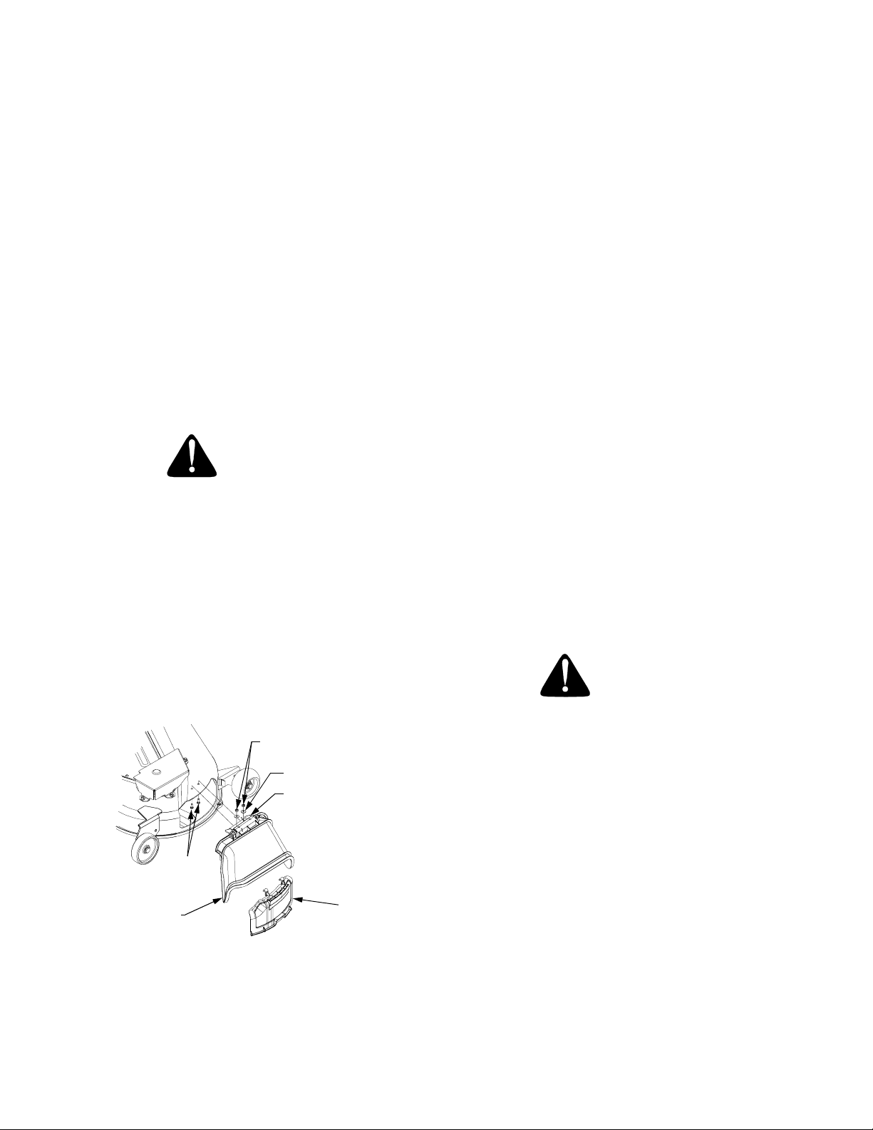
A. ATTACHING THE CHUTE DEFLECTOR
WARNING
Do not operate the mower deck without the chute
defelector installed and in its down position.
1. Remove the hex cap screws, bell washers and hex
nuts installed in the deck at the chute opening.
2. Position the hinge bracket of the deflector assembly to align with the holes in deck. Insert the hex
cap screws from the underside of the deck and secure with the bell washers and hex nuts. Note: the
crowned (rounded) surface of the washers go toward the hex nuts.
Section Page
VI Off-Season Storage ............................. 45
VII Mowing................................................. 46
Optional Equipment and Accessories . 47
Maintenance Chart............................... 48
Trouble Shooting.................................. 49
Lubrication Table ............................... 51
Lubrication Guides .............................. 52
Slope Gauge ........................................ 55
Specifications....................................... 57
Warranty — Commercial Use .............. 58
Warranty — Residential Use................ 59
Maintenance Parts Chart .................... 60
B. LIFT ASSIST SPRING
The RH lift assist spring may have been received in the
manual bag, or may have been installed at the factory.
The RH lift assist rod is installed on the tractor and, if the
spring is NOT installed, suspended with a rubber band
for shipment. From beneath the right rear fender, remove the rubber band from the rod and pigtail hook.
If the lift assist spring was shipped in the manual bag,
refer to INSTALLING LIFT ASSIST SPRING in SEC-
TION V (page 33) for installation instructions.
C. CONNECT THE BATTERY
WARNING
HEX NUTS
BELL WASHERS
HINGE BRACKET
HEX CAP
SCREWS
CHUTE
DEFLECTOR
ASSEMBLY
3. Refer to SECTION V- MOWER DECK when installing the mulching plug.
(PACKED WITH MANUAL)
MULCHING
PLUG
Battery posts, terminals and related accessories
contain lead and lead compounds. Wash hands
after handling.
The tractor is shipped with an activated sealed battery,
with the positive battery cable factory connected. The
negative cable must be connected.
Note: Make sure the ignition switch is in the "OFF" position before attaching the battery cables.
1. Pull the protective cap off the negative terminal of
the battery, and remove the hex cap screw and nut
from the free end of the negative battery cable.
2. Connect the negative battery cable (heavy black)
and ground wire (green) to negative terminal (—)
of the battery using the hex cap screw and nut.
3. Slide the black terninal cover over the negative
terminal of the battery.
3
Page 4

WARNING
• The engine exhaust, some of its constituents, and certain vehicle components contain or emit chemicals known
to the State of California to cause cancer, birth defects or other reproductive harm.
• This unit is equipped with an internal combustion engine and should not be used on or near any unimproved
forest-covered, brush-covered, or grass-covered land unless the engine’s exhaust system is equipped with a
spark arrester meeting applicable local or state laws (if any). If a spark arrester is used, it should be maintained
in effective working order by the operator.
• In the State of California, the above is required by law (Section 4442 of the California Public Resources Code).
Other States may have similar laws. Federal laws apply to federal lands. A spark arrester muffler is available
at your nearest engine authorized service center.
IMPORTANT
THIS SYMBOL POINTS OUT IMPORTANT SAFETY INSTRUCTIONS WHICH, IF NOT FOLLOWED,
COULD ENDANGER THE PERSONAL SAFETY AND/OR PROPERTY OF YOURSELF AND
OTHERS. READ AND FOLLOW ALL INSTRUCTIONS IN THIS MANUAL BEFORE ATTEMPTING
TO OPERATE YOUR UNIT. FAILURE TO COMPLY WITH THESE INSTRUCTIONS MAY RESULT
IN PERSONAL INJURY. WHEN YOU SEE THIS SYMBOL— HEED ITS WARNING.
Your lawn mower was built to be operated according to the rules for safe operation
in this manual. As with any type of power equipment, carelessness or error on the
DANGER
I. GENERAL OPERATION
1. Read, understand and follow all instructions in the
manual and on the machine before starting. Keep
this manual in a safe place for future and regular
reference and for ordering replacement parts
2. Only allow responsible individuals familiar with
the instructions to operate the machine. Know the
controls and how to stop the machine quickly.
3. Do not put hands or feet under the cutting deck or
near rotating parts.
4. Clear the area of objects such as rocks, toys,
wire, etc. which could be picked up and thrown by
the blades. A small object may have been
overlooked and could be accidentally thrown by
the mower in any direction and cause injury to
you or a bystander. To help avoid a thrown
objects injury, keep children, animals, bystanders
and helpers at least 75 feet from the mower while
it is in operation. Always wear safety glasses with
side shields or safety goggles during operation or
while performing an adjustment or repair, to
protect eyes from foreign objects. Stop the blades
when crossing gravel drives, walks or roads.
part of the operator can result in injury. This lawn mower is capable of amputating
hands and feet or throwing objects. Failure to observe the following safety
instructions could result in serious injury or death.
SAFE OPERATION PRACTICES
5. Be sure the area is clear of other people before
mowing. Stop machine if anyone enters the area.
6. Never carry passengers.
7. Disengage the blades before shifting into reverse
and backing up. Always look down and behind
before and while backing.
8. Be aware of the mower and attachment discharge
direction and do not point it at anyone. Do not
operate the mower without either the entire grass
catcher or the chute guard in place.
9. Slow down before turning. Operate the machine
smoothly. Avoid erratic operation and excessive
speed.
10. Never leave a running machine unattended.
Always turn off the blades, place the transmission
in neutral, set the parking brake, stop the engine
and remove key before dismounting.
11. Turn off blades when not mowing.
12. Stop the engine and wait until the blades come to
a complete stop before (a) removing the grass
catcher or unclogging chute, or (b) making any
repairs, adjusting or removing any grass or debris.
4
Page 5

13. Mow only in daylight or good artificial light.
DO:
14. Do not operate the machine while under the
influence of alcohol or drugs.
15. Watch for traffic when operating near or crossing
roadways.
16. Use extra care when loading or unloading the
machine into a trailer or truck. This unit should not
be driven up or down a ramp onto a trailer or truck
under power, because the unit could tip over
causing serious personal injury. The unit must be
pushed manually on a ramp to load or unload
properly.
17. Never make a cutting height adjustment while the
engine is running if the operator must dismount to
do so.
18. Wear sturdy, rough-soled work shoes and closefitting slacks and shirts. Do not wear loose fitting
clothes or jewelry. They can be caught in moving
parts. Never operate a unit in bare feet, sandals
or sneakers.
19. Check overhead clearance carefully before
driving under power lines, wires, bridges or low
hanging tree branches, before entering or leaving
buildings, or in any other situation where the
operator may be struck or pulled from the unit,
which could result in serious injury.
20. Disengage all attachment clutches, thoroughly
depress the brake pedal and shift into neutral
before attempting to start the engine.
21. Your mower is designed to cut normal residential
grass of a height no more than 10”. Do not
attempt to mow through unusually tall, dry grass
(e.g. pasture) or piles of dry leaves. Debris may
build up on the mower deck or contact the engine
exhaust presenting a potential fire hazard.
Mow up and down slopes, not across.
Remove obstacles such as rocks, limbs, etc.
Watch for holes, ruts or bumps. Uneven terrain could
overturn the machine. Tall grass can hide obstacles.
Use slow speed. Choose a low enough gear so that
you will not have to stop or shift while on the slope. Always keep the machine in gear when going down
slopes to take advantage of engine braking action.
Follow the manufacturer’s recommendations for wheel
weights or counterweights to improve stability.
Use extra care with grass catchers or other attachments. These can change the stability of the machine.
Keep all movement on the slopes slow and gradual.
Do not make sudden changes in speed or direction.
Rapid engagement or braking could cause the front of
the machine to lift and rapidly flip over backwards,
which could cause serious injury.
Avoid starting or stopping on a slope. If the tires lose
traction, disengage the blades and proceed slowly
straight down the slope.
DO NOT:
Do not turn on slopes unless necessary; then, turn
slowly and gradually downhill, if possible.
Do not mow near drop-offs, ditches or embankments.
The mower could suddenly turn over if a wheel is over
the edge of a cliff or ditch, or if an edge caves in.
Do not mow on wet grass. Reduced traction could
cause sliding.
Do not try to stabilize the machine by putting your foot
on the ground.
Do not use the grass catcher on steep slopes.
22. Use only accessories approved for this machine
by Cub Cadet. Read, understand and follow all
instructions provided with the approved
accessory.
II. SLOPE OPERATION
Slopes are a major factor related to loss of control and
tip-over accidents, which can result in severe injury or
death. All slopes require extra caution. If you cannot
back up the slope or if you feel uneasy on it, do not
mow it.
For your safety, use the slope gauge included as part
of this manual to measure slopes before operating this
unit on a sloped or hilly area. If the slope is greater
than 15° as shown on the slope gauge, do not operate
this unit on that area or serious injury could result.
III. CHILDREN
Tragic accidents can occur if the operator is not alert
to the presence of children. Children are often
attracted to the machine and the mowing activity.
Never assume that children will remain where you
last saw them.
1. Keep children out of the mowing area and in
watchful care of an adult other than the operator.
2. Be alert and turn the machine off if children enter
the area.
3. Before and when backing up, look behind and
down for small children.
4. Never carry children, even with the blades off.
They may fall off and be seriously injured or may
interfere with safe machine operation.
5
Page 6

5. Never allow children under 14 years old to
operate the machine. Children 14 years and over
should only operate the machine under close
parental supervision and proper instruction.
6. Use extra care when approaching blind corners,
shrubs, trees or other objects that may obscure
your vision of a child or other hazard.
7. Remove the key when the machine is left
unattended to prevent unauthorized operation.
IV. SERVICE
1. Use extreme care in handling gasoline and other
fuels. They are extremely flammable and the
vapors are explosive.
a. Use only an approved container.
b. Never remove fuel cap or add fuel with the en-
gine running. Allow the engine to cool at least
two minutes before refueling.
c. Replace the fuel cap securely and wipe off any
spilled fuel before starting the engine as it may
cause a fire or explosion.
d. Extinguish all cigarettes, cigars, pipes and oth-
er sources of ignition.
e. Never refuel the machine indoors because fuel
vapors will accumulate in the area.
f. Never store the fuel container or machine
inside where there is an open flame or spark,
such as a gas hot water heater, space heater
or furnace.
2. Never run a machine inside a closed area.
3. To reduce fire hazard, keep the machine free of
grass, leaves or other debris build-up. Clean up
oil or fuel spillage. Allow the machine to cool at
least 5 minutes before storing.
4. Before cleaning, repairing or inspecting, make
certain the blade and all moving parts have
stopped. Disconnect the spark plug wire, and
keep the wire away from the spark plug to prevent
accidental starting.
5. Check the blade and engine mounting bolts at frequent intervals for proper tightness. Also visually
inspect blades for damage (e.g., excessive wear,
bent, cracked). Replace with blades which meet
original equipment specifications.
6. Keep all nuts, bolts and screws tight to be sure
the equipment is in safe working condition.
7. Never tamper with safety devices. Check their
proper operation regularly. Use all guards as
instructed in this manual.
8. After striking a foreign object, stop the engine,
remove the wire from the spark plug and
thoroughly inspect the mower for any damage.
Repair the damage before restarting and
operating the mower.
9. Grass catcher components are subject to wear,
damage and deterioration, which could expose
moving parts or allow objects to be thrown. For
your safety protection, frequently check the
components and replace with manufacturer’s
recommended parts when necessary.
10. Mower blades are sharp and can cut. Wrap the
blades or wear gloves, and use extra caution
when servicing blades.
11. Check brake operation frequently. Adjust and
service as required.
12. Muffler, engine and belt guards become hot
during operation and can cause a burn. Allow to
cool down before touching.
13. Do not change the engine governor settings or
overspeed the engine. Excessive engine speeds
are dangerous.
14. Observe proper disposal laws and regulations.
Improper disposal of fluids and materials can
harm the environment and the ecology.
a. Prior to disposal, contact your local
Environmental Protection Agency to
determine the proper method for disposing of
the waste. Recycling centers are established
to properly dispose of materials in an
environmentally safe fashion.
b. Use proper containers when draining fluids.
Do not use food or beverage containers that
may mislead someone into drinking from
them. Properly dispose of the containers immediately following the draining of fluids.
c. DO NOT pour oil or other fluids into the
ground, down a drain or into a stream, pond,
lake, or other body of water. Observe Environmental Protection Agency regulations when
disposing of oil, fuel, coolant, brake fluid, filters, batteries, tires and other harmful waste.
15. We do not recommend the use of a pressure
washer or garden hose to clean your unit. They
may cause damage to electrical components;
spindles; pulleys; bearings; or the engine. The
use of water will result in shortened life and
reduce serviceability.
WARNING - YOUR RESPONSIBILITY: Restrict the use of this power machine to persons who
read, understand and follow the warnings and instructions in this manual and on the machine.
6
Page 7

PRODUCT GRAPHICS
Keep product safety graphics (decals) clean. Replace
any safety graphic that is damaged, destroyed, miss-
STARTING INSTRUCTIONS
BE FAMILIAR WITH CONTROLS BEFORE
1.
STARTING ENGINE AND OPERATING.
SET CHOKE, MOVE THROTTLE TO MID
2.
POSITION AND DEPRESS BRAKE PEDAL.
TURN KEY TO THE START POSITION.
3.
4.
AFTER ENGINE STARTS OPEN CHOKE.
STOPPING INSTRUCTIONS
1.
DISENGAGE PTO AND SET PARKING BRAKE.
2.
MOVE THROTTLE CONTROL TO MID
POSITION AND TURN KEY OFF.
WARNING
!
•
AVOID SERIOUS INJURY OR DEATH.
•
READ OPERATORS MANUAL AND ALL
WARNING LABELS BEFORE USING
MACHINE.
•
GO UP AND DOWN SLOPES, NOT ACROSS.
•
AVOID SUDDEN TURNS.
•
DO NOT OPERATE UNIT WHERE IT COULD
SLIP OR TIP.
•
IF MACHINE STOPS GOING UPHILL, STOP
PTO AND BACK DOWN HILL SLOWLY.
•
DO NOT MOW WHEN CHILDREN OR
OTHERS ARE AROUND.
•
NEVER CARRY CHILDREN.
•
LOOK DOWN AND BEHIND BEFORE AND
WHILE BACKING.
•
KEEP SAFETY DEVICES [G UARDS, SHIELDS,
AND SWITCHES] IN PLACE AND WORKING.
•
REMOVE OBJECTS THAT COULD BE
THROWN BY THE BLADES.
•
KNOW LOCATION AND FUNCTION OF ALL
CONTROLS.
•
BE SURE THE BLADES AND THE ENGINE
ARE STOPPED BEFORE PLACING HANDS
OR FEET NEAR BLADES.
•
BEFORE LEAVING OP ERATOR'S
POSITION, DISENGAGE PTO, ENGAGE
BRAKE LOCK, SHUT OFF ENGINE AND
REMOVE KEY.
ing, painted over or can no longer be read. Replacement safety graphics are available through your
dealer.
SAFETY GRAPHIC – LOCATED ON
LEFT SIDE OF MOWER DECK
DEFLECTOR and SAFETY GRAPHIC –
LOCATED ON RIGHT SIDE OF DECK
GENERAL SAFETY INSTRUCTIONS
WARNING – LOCATED ON RIGHT
SIDE OF RUNNING BOARD
HANDS AND FEET SAFETY GRAPHIC–
LOCATED ON DEFLECTOR CHUTE
SAFETY GRAPHIC – LOCATED
ON LEFT SIDE OF DECK
7
Page 8

TO THE OWNER
This Operator’s Manual is an important part of your new tractor. The information contained in this manual has been
prepared in detail to help you better understand the features, correct operation, adjustments, and maintenance of
your tractor. The performance and dependability of this tractor rely greatly on the manner in which it is operated and
maintained. Therefore, it is recommended that all operators of the tractor carefully read this manual and fully understand its operation. Also keep the manual available for reference to ensure proper operation, and that maintenance
procedures are performed as scheduled to assure the tractor’s optimal mechanical condition.
NOTE: All references to LEFT, RIGHT, FRONT, and REAR, unless specifically stated otherwise, indicate that rela-
tive position on the tractor when facing forward while seated in the operator’s seat.
CAUTION: DO NOT tow your Model 2518 tractor. Towing will damage the transmission. Place the tractor on a
LEVEL SURFACE before pulling the transmission release lever to the disengaged position.
Your local authorized Cub Cadet dealer is interested in the performance you receive from your tractor, and with the
maintenance needed to ensure the satisfactory operation of your tractor. The dealer has trained service personnel
familiar with the latest servicing information, is equipped with the latest tools, and has a complete line of genuine
Cub Cadet service parts which assure proper fit and high quality.
CALLING SERVICE INFORMATION
The engine manufacturer is responsible for all engine-related issues with regards to performance, power-rating, and
specifications.
If you have difficulties with the tractor and/or equipment; have any questions regarding the operation or maintenance
of this equipment; or desire additional information not found in this manual, contact your nearest authorized Cub
Cadet dealer. If you need assistance in locating a dealer in your area, contact the Customer Dealer Referral Line by
calling:
1-877-282-8684
To obtain top performance and assure economical operation, the tractor should be inspected by your authorized
dealer periodically or at least once a year, depending on its hours of use. Before calling your dealer, make sure that
you have your model number(s) and manufacturing date available for the dealer.
RECORDING MODEL AND SERIAL NUMBER INFORMATION
Product identification plates are provided for major components of your tractor. The numbers on these plates are
important if your tractor should require dealer service, or if you need additional information on your tractor. Prior to
using your tractor for the first time, record the numbers from the identification plates in the appropriate spaces provided below.
The chassis model plate, showing the factory model number and Mfg. Date (See Figure 1) can be found on the
underside of the seat mounting base. Pivot the seat foward to locate the decal.
The engine serial number decal (See Figure 2) is located on the engine blower housing.
Hood Model Factory Model No. Mfg. Date
Delivery Date Engine Model/Spec. No. Engine Serial No.
XXXXXXXXXXX XXXXXXXXXX
Model Number Mfg. Date
CUB CADET LLC
P. O. BOX
www.cubcadet.com
DEALER LOCATOR PHONE NUMBER:
361131
CLEVELAND, OH 44136
877-282-8684
Figure 1 Figure 2
8
Page 9
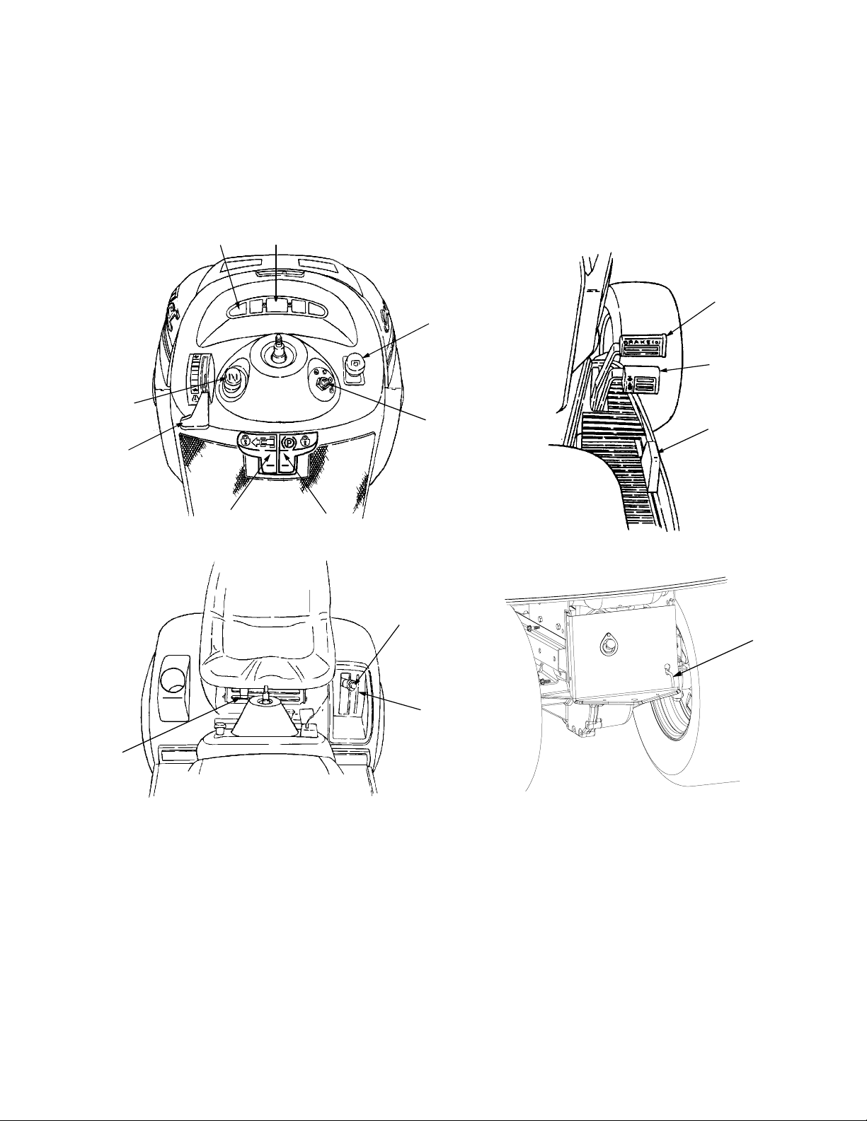
SECTION I. CONTROLS AND INDICATORS
Your Cub Cadet Tractor has been safety engineered.
This section gives a brief description of the function
and location of the various controls and indicators.
AB
F
E
H
G
Thoroughly acquaint yourself with all the controls and
indicators before attempting to start or operate the
tractor.
I
C
J
D
K
N
A. Low Oil Indicator
B. Hour Meter
C. Power Take-Off (PTO) Control Switch
D. Ignition/Light Switch
E. Throttle Control Lever
F. Choke Control
G. Brake Pedal Lock
H. Cruise Control Lever
L
O
M
I. Brake Pedal
J. Forward Control Pedal
K. Reverse Control Pedal
L. Lift Handle
M. Lift Height Indicator
N. Seat Adjustment Lever
O. Transmission Release Lever
P. Fuses (Not Shown)
Q. Safety Interlock Switches (Not Shown)
Figure 3
9
Page 10
A. LOW OIL INDICATOR
This indicator will illuminate when the engine oil level is
low. If this indicator illuminates, stop the tractor immediately and check the engine oil level. If the oil level is
within the operating range, but the light remains on,
contact your Cub Cadet dealer.
E. THROTTLE CONTROL LEVER
This lever controls the speed of the engine. When
set in a given position, the control cable will maintain
a uniform engine speed.
NOTE
CAUTION
Operating the tractor with low oil level or pressure could result in severe engine damage.
B. HOUR METER
The hour meter operates whenever the ignition key is
in the “ON” position. Record the actual hours of tractor
operation to ensure all maintenance procedures are
completed according to the schedule in this manual.
C. POWER TAKE–OFF (PTO) CONTROL SWITCH
The power take-off control switch operates the front
electric PTO clutch. Pull the switch knob to engage
(“RUN”), or push the knob to disengage (“OFF”) the
PTO clutch.
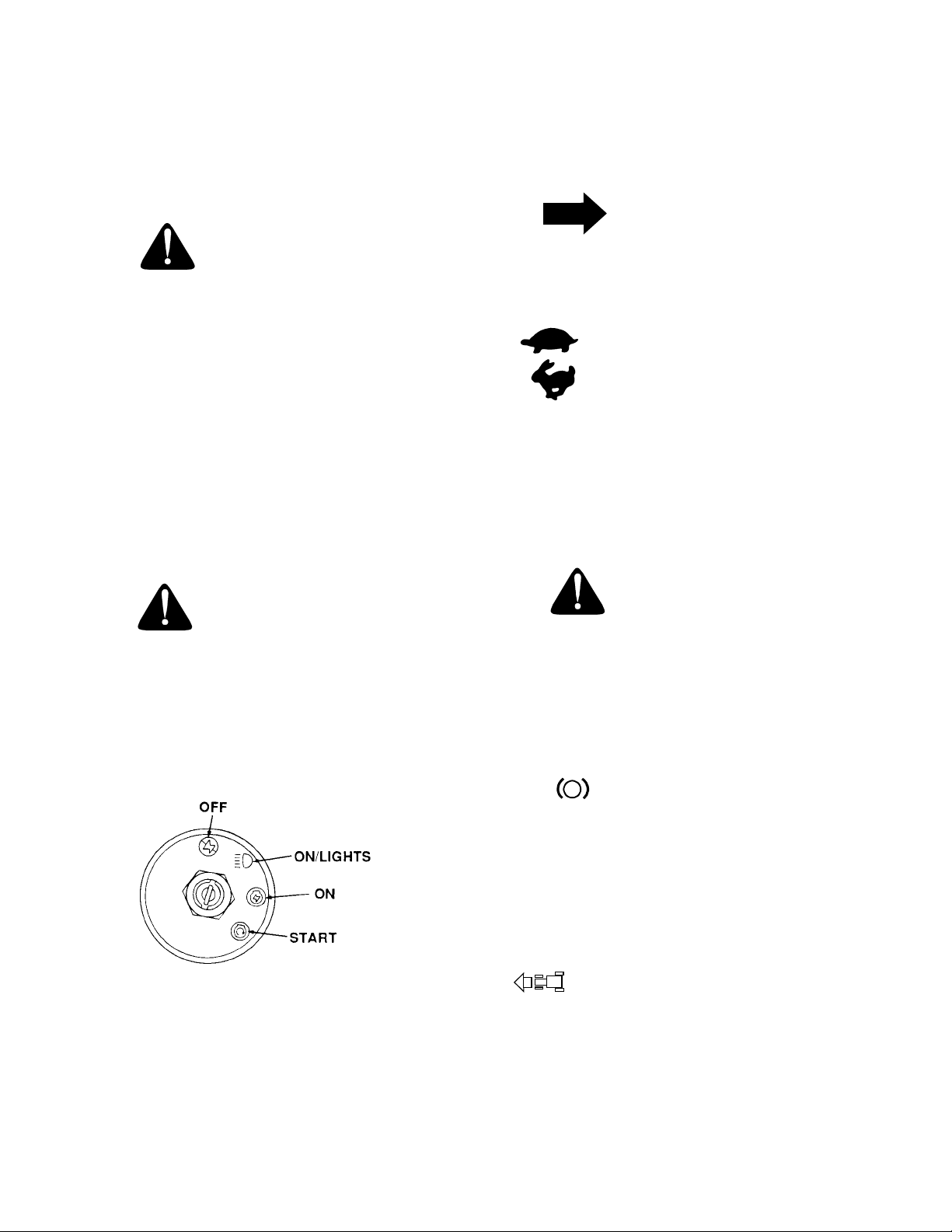
D. IGNITION/LIGHT SWITCH
WARNING
To prevent accidental starting and/or battery
discharge, remove the key from the ignition
switch when the tractor is not in use.
The combination lights and ignition switch is a four
position switch. (See Figure 4)
When using power take-off operated equipment, best performance is achieved with the
throttle lever in the “FAST” position.
This symbol shows slow position.
This symbol shows fast position.
F. CHOKE CONTROL
The choke control is operated manually. Pull the
knob out to ckoke the engine; push the knob in to
open the choke.
G. BRAKE PEDAL LOCK
WARNING
The hydrostatic transmission will not hold the
tractor on a hill. Normal internal leakage in the
transmission will allow the tractor to roll downhill. To avoid an accident and/or possible injury, engage the brake pedal lock.
The brake lock lever, located in the center of the
dash panel below the steering wheel, is identified
with the symbol. Always engage the brake
pedal lock when dismounting the tractor. To engage
the brake pedal lock, depress the brake pedal and
push down on the brake pedal lock lever. Hold the
lever down while releasing the brake pedal. The lever should lock in the down position.
P
Figure 4
H. CRUISE CONTROL LEVER
The cruise control lever, located in the center of the
dash panel below the steering wheel, is identified with
the symbol. This lever can be used to maintain a desired “foot free” forward speed in areas
where constant speed changes are not required. Refer to Section II- OPERATION for instructions on how
to use this feature.
10
Page 11
I. BRAKE PEDAL
The brake pedal is located at the front of the right running board above the forward control pedal. Press
down to stop the tractor and disengage the cruise control. The brake pedal must be fully depressed to activate the safety interlock switch when starting the
tractor.
J. FORWARD CONTROL PEDAL
The forward control pedal is located at the front of the
right running board below the brake pedal. Slowly
press down on the pedal to start moving forward. The
forward ground speed of the tractor is directly affected
by the distance the pedal is depressed.
K. REVERSE CONTROL PEDAL
WARNING
Check behind the tractor to be sure the area is
clear of people, pets or obstacles. Use a slower
speed to maintain control of the tractor when
traveling in reverse.
The reverse control pedal is located in the right front
running board rearward of the the brake and forward
control pedals. Press the pedal downward to move in
reverse.
L. LIFT HANDLE
The lift handle is located in the left fender and is used
to raise and lower equipment used with the tractor. The
equipment can be set in any of six positions by depressing the top button on the handle, moving the handle to the desired position, then releasing the button. It
may be necessary to push or pull slightly on the handle
to depress the button. There is a lift assist spring which
reduces the effort needed to lift attachments. To adjust
spring tension refer to ADJUSTMENTS in Section III.
Figure 5
O. TRANSMISSION RELEASE LEVER
The transmission release lever is located at the back of
the tractor in the rear drawbar. When engaged, this lever opens a hydrostatic pump bypass valve, which allows the tractor to be pushed short distances by hand.
To engage the release lever, lift and pull the lever rearward through the keyhole until the flange on the rod is
outside the drawbar. Lower the lever up into the slot
and release. To disengage the release lever, pull back
on the lever, lift out of the slot and release.
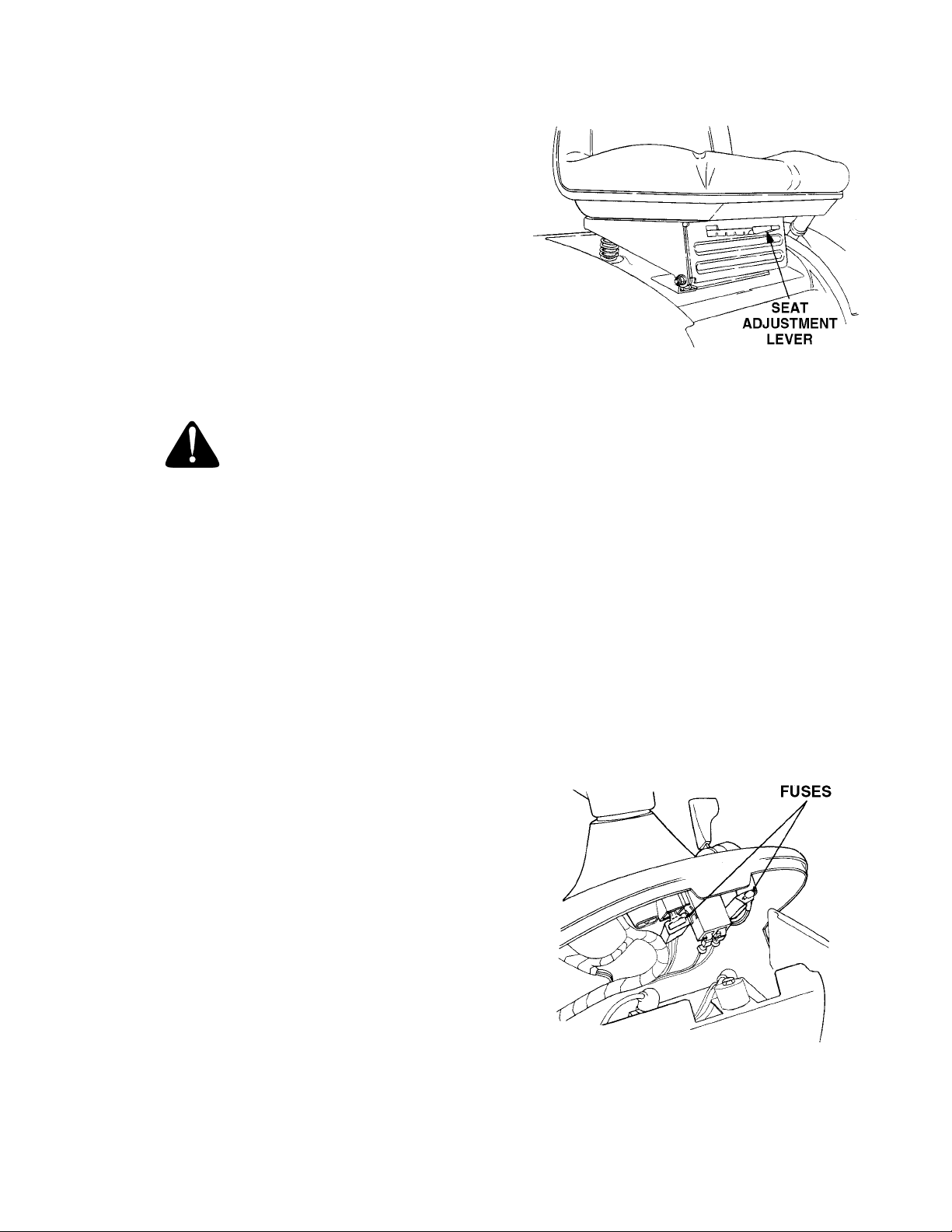
P. FUSES
The fuses are located under the hood between the indicator lamps and the hour meter (see Figure 6). Fuses
are installed to protect the tractor’s electrical circuitry
and components from damage caused by excessive
amperage.
M. LIFT HEIGHT INDICATOR
The lift height indicator is located in the left fender and
indicates the height of the deck attachment when installed.
N. SEAT ADJUSTMENT LEVER
The seat adjustment lever (see Figure 5) is used to
move the seat forward or rearward into one of five positions. See ADJUSTING THE SEAT in Section III.
Figure 6
11
Page 12
Q. SAFETY INTERLOCK SWITCHES
HOOD AND SIDE PANELS
This tractor is equipped with a safety interlock system
for the protection of the operator. If the interlock system should ever malfunction, do not operate the tractor. Contact your authorized Cub Cadet Dealer. The
safety interlock system prevents the engine from
cranking or starting unless the brake pedal is fully depressed, and the PTO switch is in the “OFF” position.
The safety interlock system will automatically shut off
the engine if the operator leaves the seat before engaging the brake lock.
The safety interlock system will automatically shut off
the engine if the operator leaves the seat with the PTO
in the “RUN” position, regardless of whether the brake
lock is engaged. The PTO switch must be moved to the
“OFF” position to restart the engine.
The safety interlock system will automatically shut off
the PTO if the reverse control pedal is depressed with
the PTO in the “RUN” position. To re-engage the PTO,
release the reverse control pedal, move the PTO
switch to the “OFF” position, then again pull the switch
to the “RUN” position.
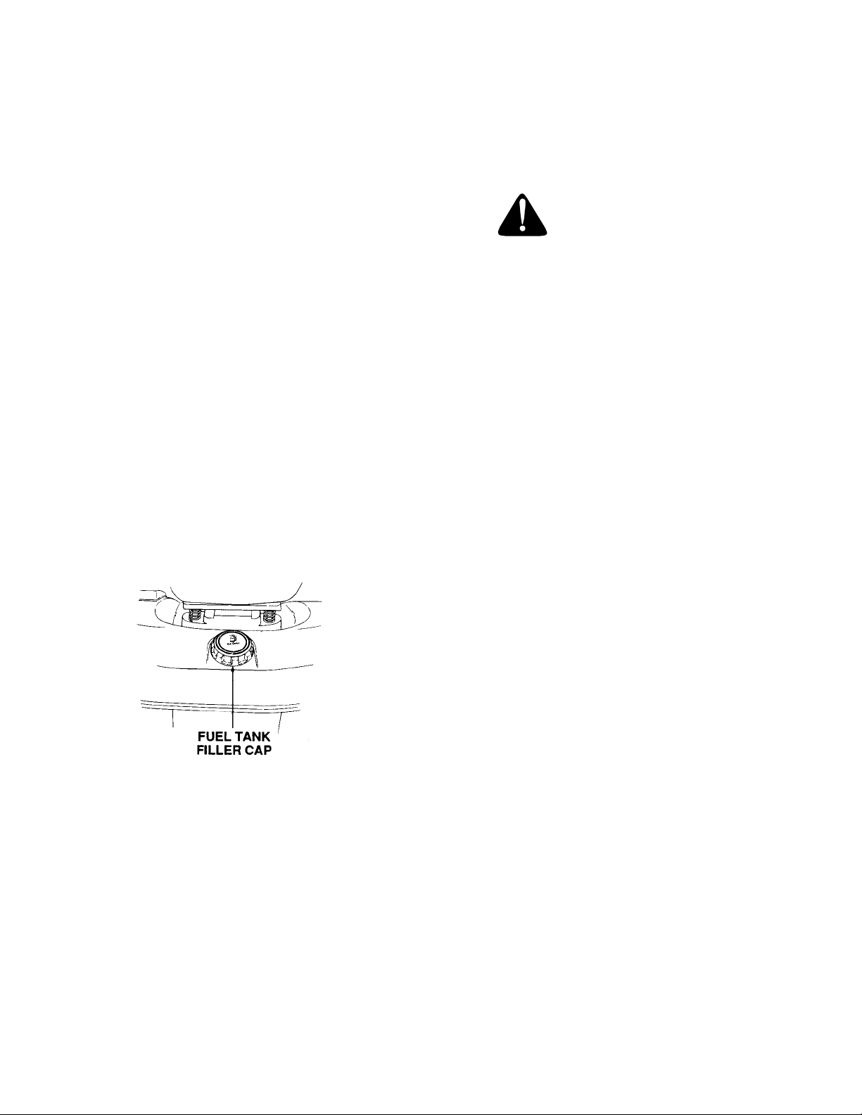
FUEL TANK
The fuel tank is located under the rear fender. The filler
cap is in the center/rear of the fender (see Figure 7).
The tractor hood is arranged to swing up and forward
for easy access to the engine compartment (see Figure 8). Whenever engine maintenance is required, the
side panels can be removed.
WARNING
If the engine has been recently run, the engine,
muffler and surrounding metal surfaces will be
hot and can cause burns to the skin. Allow the
tractor to cool and use caution when removing
the side panels.
To remove either the right or left side panel, refer to
Figure 8 and proceed as follows:
1. Engage the brake lock and raise the hood.
2. Loosen, but do not remove, the rear wing nut and
upper front wing nut.
3. Grasp the side panel just behind the grille and pull
outward to release the side panel from the
tapered bushings on the grille.
4. Slide the side panel forward and out of the groove
in the dash panel.
Figure 7
To install either the right or left side panel, refer to Figure 8 and proceed as follows:
1. Slide the rear of panel into the groove in the dash
panel.
2. Position the notch of the rear side panel tab on
the threads of the bulkhead rod, between the
bulkhead and wing nut.
3. Press the slots of the front side panel flange onto
the tapered retainers, between the retainers and
the grille.
4. Tighten the rear and upper front wing nuts and
close the hood.
12
Page 13
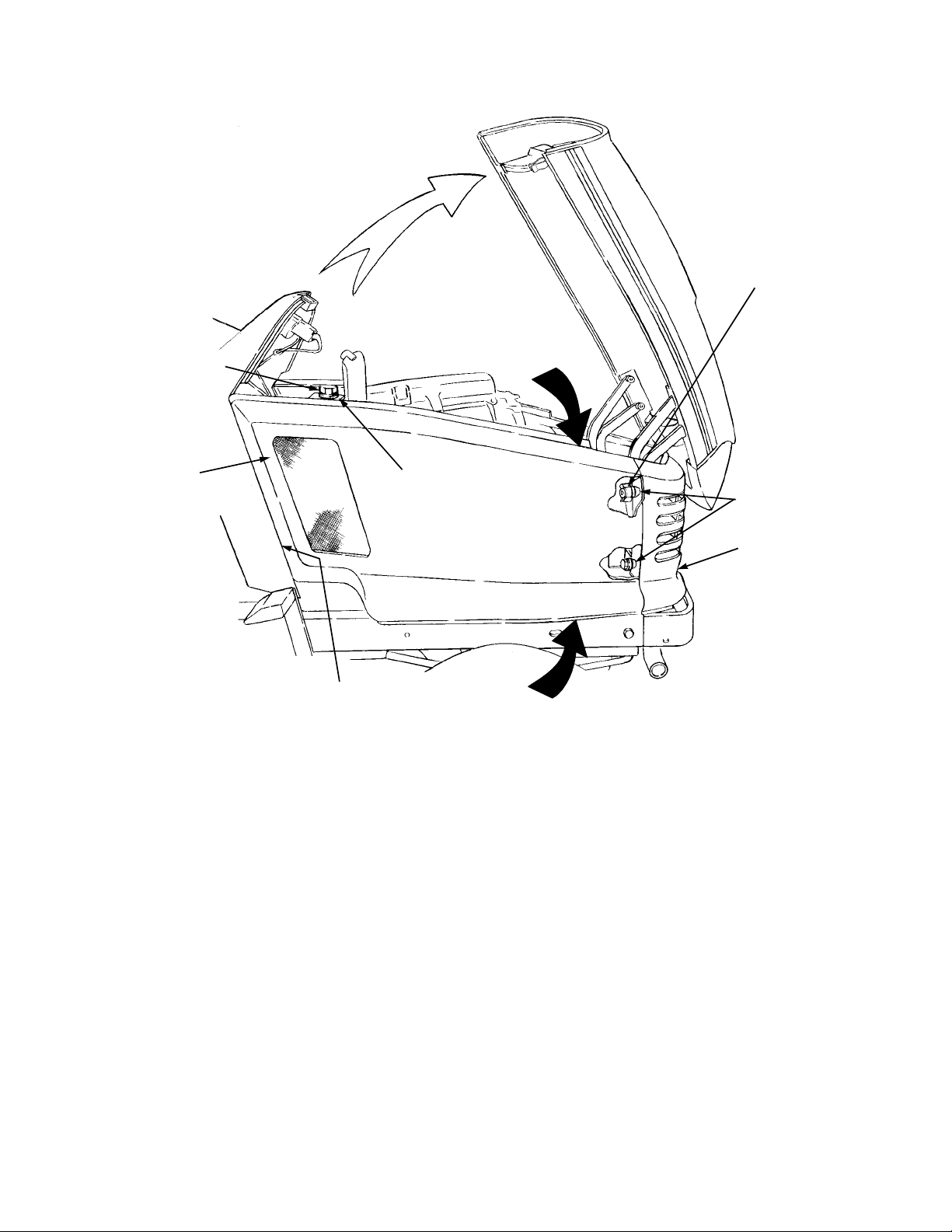
UPPER FRONT
WING NUT
REAR WING NUT
SIDE PANEL
GROOVE IN
DASH PANEL
REAR TAB
ON PANEL
GRASP
RETAINER WITH
TAPERED GUIDE
GRILLE
GRASP
Figure 8
13
Page 14

WARNING
SECTION II. OPERATION
Gasohol (up to 10% ethyl alcohol, 90% unleaded
gasoline by volume) is an approved fuel. Other
gasoline/alcohol blends are not approved.
RECEIVE INSTRUCTION - Read the
operator’s manual. Learn to operate this
machine SAFELY. Don’t risk INJURY or
DEATH.
1. Before starting the engine or beginning
operation, be familiar with the controls. The
operator must be seated, the PTO switch in
the “OFF” position and the brake pedal fully
depressed.
2. Keep all shields in place. Keep away from
moving parts.
3. NO RIDERS! Keep all people and pets a
safe distance away. Look behind to both
sides before backing up.
4. DO NOT direct the mower discharge at
people.
5. Avoid slopes. Tractors can be rolled over.
6. Before leaving the operator’s seat: Shut off
the PTO, engage the brake pedal lock, shut
off the engine and remove the ignition key.
Wait for all movement to stop before
servicing or cleaning.
Methyl Tertiary Butyl Ether (MTBE) and unleaded
gasoline blends (up to a maximum of 15% MTBE
by volume) are approved fuels. Other gasoline/
ether blends are not approved.
4. Check the engine and transmission oil levels.
5. Clean the air cleaner element if necessary.
6. Check the tire inflation pressures.
7. Adjust the seat for operator’s maximum comfort,
visibility and for maintaining complete control of
the tractor.
8. Remove the side panels and clean any
accumulated grass and debris from the engine air
inlet screen. Also clean the dash air intake screen,
grille and side panels to ensure adequate cooling.
9. Refer to the various sections of the Owner’s
Manual for additional information.
STARTING THE ENGINE
7. Do not fill the fuel tank when the engine is
running or while the engine is hot. Tighten
the fuel cap securely.
BEFORE OPERATING YOUR TRACTOR
1. Before you operate the tractor, study this manual
carefully. It has been prepared to help you operate
and maintain your tractor with utmost efficiency.
2. Familiarize yourself with the operations of all the
instruments and controls.
3. This engine is certified to operate on unleaded
gasoline. For best results, fill the fuel tank with only
clean, fresh, unleaded gasoline with a pump
sticker octane rating of 87 or higher. In countries
using the Research method, it should be 90 octane
minimum.
Unleaded gasoline is recommended because it
leaves less combustion chamber deposits.
Leaded gasoline may be used in areas where
unleaded is not available and exhaust emissions
are not regulated. Be aware however, that the
cylinder head may require more frequent service.
WARNING
For personal safety, the operator must be sitting
in the tractor seat when starting the engine.
WARNING
This unit is equipped with a safety inerlock
system designed for the protection of the
operator. Do not operate the tractor if any part
of the interlock system is malfunctioning.
Periodically check the functions of the interlock
system for proper operation as described
below:
• The safety interlock system prevents the engine from cranking or starting unless the
brake pedal is fully depressed and the PTO
clutch engagement switch is in the “OFF” position.
14
Page 15

• The safety interlock system will automatically shut off the engine if the operator leaves
the seat before engaging the brake pedal
lock.
• The safety interlock system will automatically disengage the PTO if the reverse control
pedal is pressed down with the PTO in the
“RUN” position. To re-engage the PTO, release the reverse control pedal, move the
PTO switch into the “OFF” position and then
engage the PTO while seated.
• The safety interlock system will automatically shut off the tractor engine if the operator
leaves the seat with the PTO in the “RUN”
position.
1. Operator must be sitting in the tractor seat.
2. Pull choke control knob to full choke position. Less
choking may be necessary due to variations in
temperature, grade of fuel, etc. Little or no choking
will be needed when the engine is warm.
3. Place the throttle midway between the “SLOW”
and “FAST” position.
TRACTOR BREAK-IN PROCEDURE
CAUTION
Never operate a new engine immediately
under full load. Break it in carefully as shown
in the table below.
Engine Throttle
Period
1st hour X None
2nd hour
3rd through
12th hour
Control Lever
Position Load
1/2 3/4 Full
X
X
X
X
Light drawbar load
Mowing with tractor
at slow groundspeed
Medium drawbar
load
Normal mowing
or
or
4. Place the PTO switch in the “OFF” position.
5. Fully depress the brake pedal.
6. Turn the ignition key clockwise to the “START”
position and release it as soon as the engine
starts; however, do not crank the engine
continuously for more than 10 seconds at a time. If
the engine does not start within this time, turn the
key “OFF” and wait a minute to allow the engine’s
starter motor to cool, then try again.
7. After the engine starts, slowly release the brake
pedal. As the engine warms up, gradually push the
choke control knob all the way in. Do not use the
choke to enrich the fuel mixture, except as
necessary to start the engine.
STOPPING THE ENGINE
CAUTION
Remove the key from the ignition switch to
prevent accidental starting or battery discharge
if the equipment is left unattended.
Place the PTO switch in the “OFF” position. Place the
throttle control lever between the “MID” and “FAST”
positions. Wait a moment to allow the engine speed to
stabilize, then turn the ignition key to the “OFF”
position. Remove the key from the ignition switch.
COLD WEATHER STARTING
WARNING
Engine exhaust gases are dangerous. Do not
run the engine in a confined area such as a
storage building any longer than is necessary.
Immediately move the tractor outdoors.
WARNING
For personal safety, the operator must be sitting
in the tractor seat before starting the tractor.
When starting the engine at temperatures near or below
freezing, ensure the correct viscosity motor oil is used in
the engine and the battery is fully charged. Start the
engine as follows:
1. Pull the choke all the way out to full choke position.
2. Move the throttle control lever to midway between
the “SLOW” and “FAST” position.
3. Place the PTO switch in the “OFF” position.
4. Fully depress the brake pedal.
15
Page 16

5. Turn the ingnition key to the “START” position and
hold until the engine starts; however, do not crank
the engine continuously for more than 10
seconds at a time. Once the engine starts, gradually
adjust the choke as needed to keep the engine
running until warmed up, then push the choke control
all the way in.
CAUTION
Do not use the forward or reverse control
pedals to change the direction of travel when
the tractor is in motion. Use the brake pedal to
bring the tractor to a stop before depressing
either the forward or reverse control pedal.
NOTE
If the engine fails to start after several attempts,
the engine may become flooded. If this
happens, wait a minute to allow the starter
motor to cool. Move the throttle control to the
“SLOW” position, push the choke in all the way
and momentarily crank the engine to help clear
the cylinders. With the throttle control in the
“SLOW” position and the choke all the way in,
turn the ignition key to the “START” position
while slowly pulling the choke out to a position
that will allow the engine to start. Gradually
adjust the choke as needed to keep the engine
running until warmed up, then push the choke
control all the way in.
DRIVING THE TRACTOR
CAUTION
Avoid sudden starts, excessive speed and
sudden stops.
CAUTION
Do not leave the seat of the tractor without
disengaging the PTO, depressing the brake
pedal and engaging the brake pedal lock. If
leaving the tractor unattended, also turn the
ignition key off and remove the key.
a. To move forward, slowly depress the forward
control pedal until the desired speed is
achieved.
b. To move in reverse, check that the area
behind is clear then fully depress the reverse
control pedal.
3. Using the cruise control lever.
NOTE
The cruise control feature can only be operated
in the forward direction.
a. Slowly depress the forward control pedal until
the desired speed is achieved.
b. Lightly push the cruise control lever downward
as far as possible and hold in this position.
c. While continuing to hold the cruise lever down,
lift your foot from the forward control pedal
(you should feel the cruise latch engage).
d. If properly engaged, the cruise lever and
forward control pedal should lock in the down
position, and the tractor will maintain the same
forward speed.
e. Disengage the cruise control using one of the
following methods:
• Depress the brake pedal to disengage the
cruise control and stop the tractor.
• Lightly depress the forward control pedal.
• Lift the cruise control lever upward.
NOTE
When using power take-off operated
equipment, best performance is achieved with
the throttle lever in the “FAST” position.
1. Depress the brake pedal to release the brake pedal
lock and let the pedal up. Move the throttle lever to
the position where the engine operates best for the
load to be handled.
2. Driving with forward or reverse pedals.
NOTE
Although not recommended, depressing the
reverse pedal will also disengage the cruise
control.
f. To change to the reverse direction when
operating with cruise control, depress the
brake pedal to disengage the cruise control
and stop the tractor; then depress the reverse
control pedal.
16
Page 17
DRIVING ON SLOPES
Refer to the SLOPE GAUGE on page 55 to help
determine slopes where you may not operate safely.
WARNING
Do not mow on inclines with a slope in excess
of 15 degrees (a rise of approximately 2-1/2 feet
every 10 feet). The tractor could overturn and
cause serious injury.
WARNING
Operate the tractor up and down slopes, never
across slopes. Always drive up or down the face
of a slope. Do not drive so that the tractor may
tip over sideways .
Before operating the tractor on any slope, walk the
slope to look for possible hazards such as rocks.
mounds, ruts, stumps or other surface irregularities
which could cause the tractor to be upset.
Back the tractor with implement up the steepest portion
of each slope you intend to work. If the tractor cannot
negotiate the slope in reverse, the slope is too steep to
be worked.
Avoid turns when driving on a slope. If a turn must be
made, turn down the slope. Turning up a slope greatly
increases the chance of a roll over.
Avoid stopping when driving up a slope. If it is
necessary to stop while driving up a slope, start up
smoothly and carefully to reduce the possibility of
flipping the tractor over backward.
STOPPING THE TRACTOR
1. Start and run the engine a few minutes to warm up.
2. With the mowing deck, snow thrower, etc. installed
and the engine running at approximately 50%
throttle, engage and disengage the clutch at ten
second intervals (ten seconds ON-ten seconds
OFF) five times. The engine choke may have to be
pulled out slightly to accomplish this.
3. Increase the engine speed to 75% throttle and
again engage and disengage the PTO clutch at ten
second intervals five times.
4. Make certain the PTO is disengaged and stop the
engine.
Operate the PTO clutch as follows:
1. Move the throttle control lever to approximately the
mid throttle position.
2. Pull the PTO switch to the “RUN” position.
3. Advance the throttle lever to the operating speed
(full engine speed).
4. The operator must remain in the tractor seat at all
times. If the operator should leave the seat without
turning off the power take-off switch, the tractor’s
engine will shut off.
5. The PTO clutch cannot be operated when the
tractor is driving in the reverse direction. The PTO
switch must in the “OFF” position when the reverse
control pedal is depressed, or the PTO clutch will
automatically disengage. To re-engage the PTO
clutch, release the reverse control pedal, move the
PTO switch to the “OFF” position, then again pull
the switch to the “RUN” position.
DRAWBAR
Drawbar type equipment must be hitched to the tractor
only at the hitch hole in the drawbar (See Figure 9).
CAUTION
Always engage the brake pedal lock, push the
PTO switch to the “OFF” position, lower the
equipment and shut off the engine before
dismounting. Never try to start the engine while
standing on the ground.
Fully depress the brake pedal to bring the tractor to a
complete stop (and disengage the cruise control),
engage the brake pedal lock, disengage the PTO, turn
the ignition switch to “OFF’” and remove the key from
the switch before dismounting.
OPERATING THE POWER TAKE-OFF (PTO) CLUTCH
Before operating the new clutch under load (mowing
grass, etc.), perform the following break-in procedure:
DRAWBAR
HITCH HOLE
Figure 9
17
Page 18
SECTION III. ADJUSTMENTS
This section contains adjustment information for the
Model 2518 tractor. A djustmen t informat ion for the 44
inch deck is located in Section V – Mower Deck
beginning on page 33.
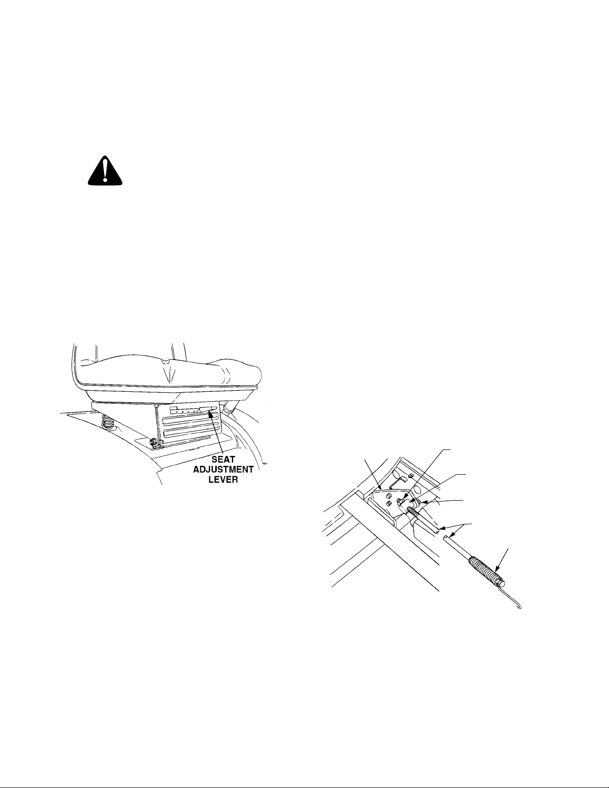
ADJUSTING THE SEAT
WARNING
Do not adjust the seat when the tractor is
moving. Adjusting the seat while the tractor is
moving could cause the operator to lose control
of the tractor.
Before starting the tract or, adjust the seat forward or
rearward to the most comfortable driving position. To
reposition the seat, move the seat adjustment lever
(see Figure 10) upward and s lide the seat forward or
rearward. Release the adjustment lever when the seat
is comfortably positioned. Gently rock the seat forward
or rearward to be sure the seat is locked in place.
To adjust the braking force, refer to Figure 11 and
proceed as follows:
1. Place the tractor on a level surface with the brake
pedal lock disengaged. Stop the tractor engine
and remove the ignition key.
2. While working from the underside of the tractor,
facing the threaded end of the rod:
• Remove the internal cotter pin from the brake
rod adjustment ferrule and di sconnect the ferrule from the brake cam.
• Loosen the hex jam nut from against the ferrule.
To increase the braking force—
Turn the ferrule clockwis e (inwar d) one ful l turn at
a time until the ferrule can be inserted into the
brake cam w hile applying a minimal tension on
the spring.
To decrease the braking force—
Turn the ferrule counterclockwise (outward) one
full turn at a time until the ferrule can be inserte d
into the brake cam while applying a minimal
tension on the spring.
3. Turn the ferrule counterclockwise (outward) one
full turn to release the slight spring tension.
Tighten the jam nut against the ferrule, then insert
the ferrule into the brak e cam and secure with the
intenal cotter pin.
Figure 10
ADJUSTING THE BRAKES
During normal ope ra tio n o f t his t racto r , th e brak es ar e
subject to wear and will need periodic examination and
adjustment.
To check the brake adjustment, position the tractor on
a firm and level surface. Stop the trac tor engine and
remove the ignition key. Pull and lock the transmission
release lever in the “TRANSMISSION RELEASED”
position. Perform the following checks:
1. Engage the brak e peda l lock. If the trac tor can be
pushed forward or rearward, the braking force
must be increased.
2. Release the brake pedal lock. If the tractor cannot
be pushed forward or rearw ard, the braking force
must be decreased.
BRAKE
CAM
HEX JAM NUT
ADJUSTMENT
FERRULE
INTERNAL
COTTER PIN
BRAKE ROD
SPRING
Figure 11. Viewed from top (fender off).
Recheck the brake adjustment to ensure proper brake
operation before operating the tractor. If brake rod
adjustment does not correct the problem, see your
authorized Cub Cadet dealer.
18
Page 19

WHEEL ALIGNMENT
The front wheels should toe-in approximately 1/8 to
1/4 inch, as measured across dimensions A and B
shown in Figure 12.
PERPENDICULAR
TO FRAME
LOWER
STEERING
ARM
Figure 12. Viewed from beneath the tractor.
FRONT WHEEL ADJUSTMENT
5. Disconnect the front ball joints from the steering
arms by removing the hex lock nuts (Refer to
Figure 13). Manually move each wheel to achieve
the required toe-in and equal D measurements.
6. Loosen the jam nuts from the ball joints (See
Figure 13).
BALL JOINT
JAM NUT
TIE ROD
HEX
LOCK
NUT
STEERING
ARM
Figure 13
7. Making sure not to move the lower steering arm or
either wheel, turn the ball joint in or out on each tie
rod as necessary to align with the hole in each
steering arm.
WARNING
Place the tractor on a firm and level surface.
To adjust the toe-in, proceed as follows:
1. Check the lower steering arm to ensure it is
perpendicular to the tractor frame (See Figure 12).
2. Place a mark at the same spot on both front
wheels; preferably the inner bead flange of the
wheel rims.
3. Rotate the wheels to position the marks at the front
horizontal diameter of the wheels, then measure
the distance between the marks and the bottom
edges of the tractor frame channels (See
measurement D in Figure 12). These two
measurements should be equal.
4. While holding the steering arms to prevent the
steering knuckles from moving, rotate the marks to
the rear horizontal diameter. Measure the distance
between the marks and the frame (See
measurement C in Figure 12). Measurement D
should be approximately 1/16 to 1/8 inch less than
measurement C on each side of the tractor.
8. Reinstall the ball joints in the steering arms and
secure with the hex lock nuts. Tighten the jam nuts
against the ball joints.
PIVOT BAR ADJUSTMENT
CAUTION
The tractor should be checked every 50 hours
of operation for play between the frame axle
channel and the pivot axle.
Check and adjust the pivot axle as follows:
1. Raise the front ot the tractor and set it on jack
stands, so the front wheels are suspended above
the ground.
CAUTION
For safety, block the rear wheels to prevent the
tractor from rolling and tipping or sliding the jack
stands.
19
Page 20
2. Pivot the ends of the axle up and down to check for
binding. If the axle is binding, loosen the lock nuts
(See Figure 14) until binding is eliminated.
PIVOT AXLE
ADJUSTMENT BOLTS
LOCK
NUT
FRAME AXLE
CHANNEL
A
A
LOCK
NUTS
PIVOT
AXLE
SECTION A-A
WARNING
Place the tractor on a firm and level surface and
chock the front wheels before raising the rear
wheels from the ground. Use jack stands to
support the rear of the tractor when raised.
2. Raise the rear of the tractor, so that the rear tires are
at least one inch above the surface, and set it on
jack stands. Make certain the jack stands are positioned to balance the tractor and prevent tipping.
WARNING
The operator presence safety circuit will stop
the engine if the seat is empty when the brake
pedal is released. If an assistant is seated when
adjusting the neutral setting, use extreme caution to prevent the tractor from tipping or rolling.
Similar precautions should be taken with any
other method of over-riding the safety circuit,
such as placing a weight in the seat. Never operate the tractor with the safety circuit disabled.
Figure 14
3. Grasping the ends of the pivot axle, attempt to
move each end of the axle forward and rearward
to check for side play between the axle and frame
channel. If play is present, gradually tighten the
lock nuts until play is minimized.
4. Repeat steps 2 and 3 until minimum play without
binding is achieved.
5. Raise the front of the tractor, remove the jack
stands, and lower the tractor to the ground.
Remove the blocks from the rear wheels.
HYDROSTATIC NEUTRAL ADJUSTMENT
The following adjustments will be necessary if the
tractor creeps forward or rearward when neither the
forward nor reverse pedals are depressed.
Checking the Transmission Neutral Setting
To check and adjust the transmission neutral setting,
proceed as follows:
1. Drive the tractor for approximately 5-10 minutes to
warm up the transmission, then stop the engine
and engage the parking brake.
3. Carefully start the tractor engine and release the
parking brake. Observe both rear wheels for
rotation in either direction.
4. If wheel rotation is observed, refer to Figure 15 and
adjust the neutral setting as follows:
a. Disconnect the rear control rod (2) from the
control arm (5) by removing the internal cotter
pin (10) from the control arm pin (6).
b. If wheel rotation stops when the rod is
disconnected, check and readjust the control
rod per the instructions below.
c. If wheel rotation continues, loosen the two hex
wash. hd. tapp screws (4) securing the neutral
return adjustment bracket (9).
d. If the rotation is in the forward direction, slide
the neutral return adjustment bracket w/
centering pin (8) rearward until the wheels just
begin to rotate in the reverse direction. Then
slowly slide the neutral return adjustment
bracket w/centering pin slightly forward until
wheel rotation stops.
e. If the rotation is in the reverse direction, slowly
slide the adjustment bracket w/centering pin
slightly forward until rotation stops.
f. Carefully tighten the hex wash. hd. tapp
screws (4), making certain the neutral return
adjustment bracket does not move.
g. Stop the engine and engage the parking
brake.
20
Page 21

CONTROL
CAM
1. Front Control Rod
2. Rear Control Rod
3. Hex Tap Screw
4. Hex Wash Hd Tapp Screw
5. Control Arm
6. Control Arm Pin
7. Neutral Arm
8. Centering Pin
9. Neutral Return Adjust. Brkt.
10. Internal Cotter Pin
3
1
Figure 15.
2
9
7
10
4
5
6
7
8
Adjusting the Control Rod
After completing the previous steps (1 thru 4) for
checking neutral setting, refer to Figure 15 and adjust
the control rod as follows:
NOTE
The brake pedal lock MUST be engaged to
properly adjust the control rod.
1. Loosen, but do not remove, the hex tap screws (3)
that fasten the front and rear control rods together.
2. While making certain to not move the front control
rod (1), control cam, or control arm (5), slide the
rear control rod (2) in the direction necessary to
directly align its hole with the control arm pin (6).
3. Slide the rear control rod onto the control arm pin
and secure with the internal cotter pin (10), then
tighten the hex tap screws. Make sure to maintain
the adjusted position of the control rods when
tightening the screws.
4. Raise the rear of the tractor, remove the jack
stands and lower the tractor.
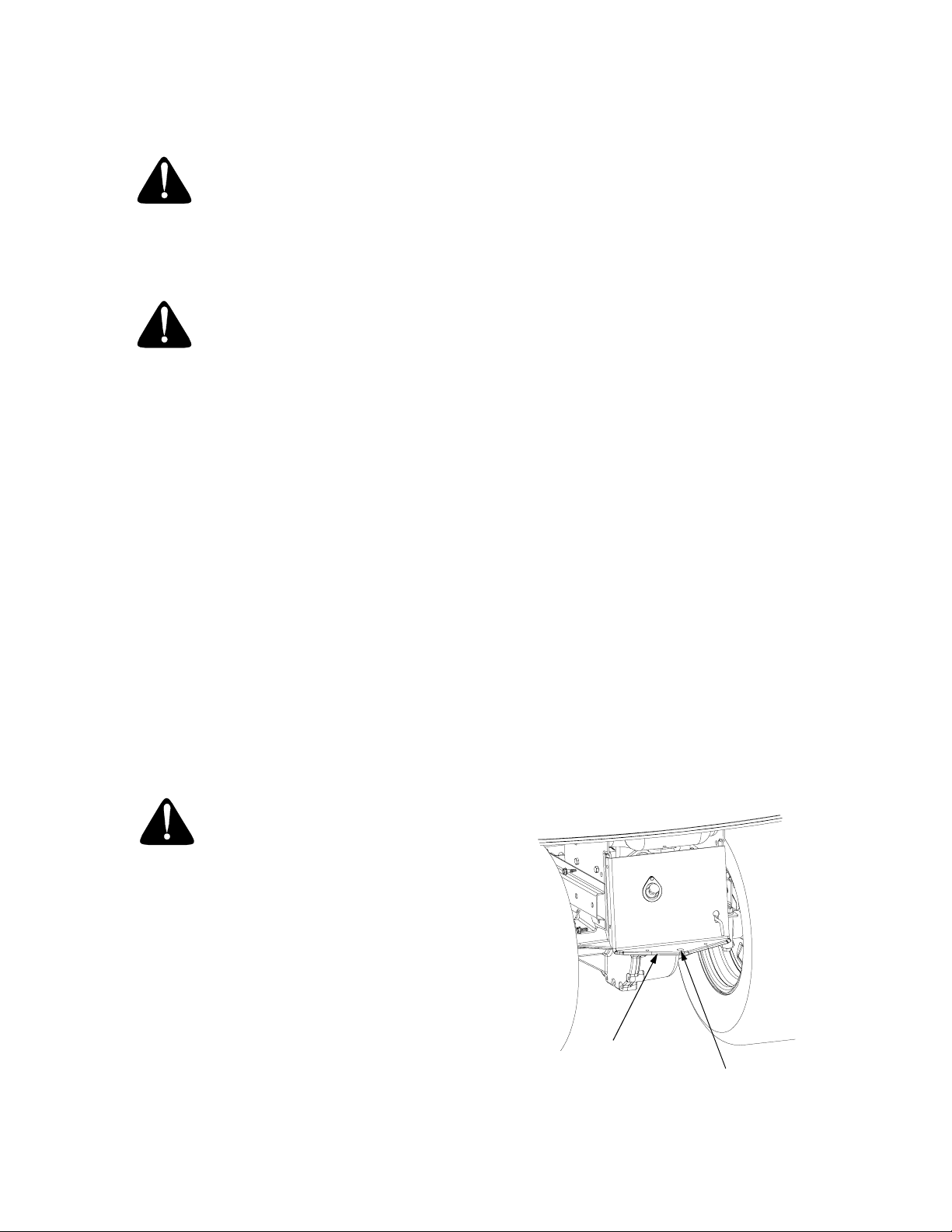
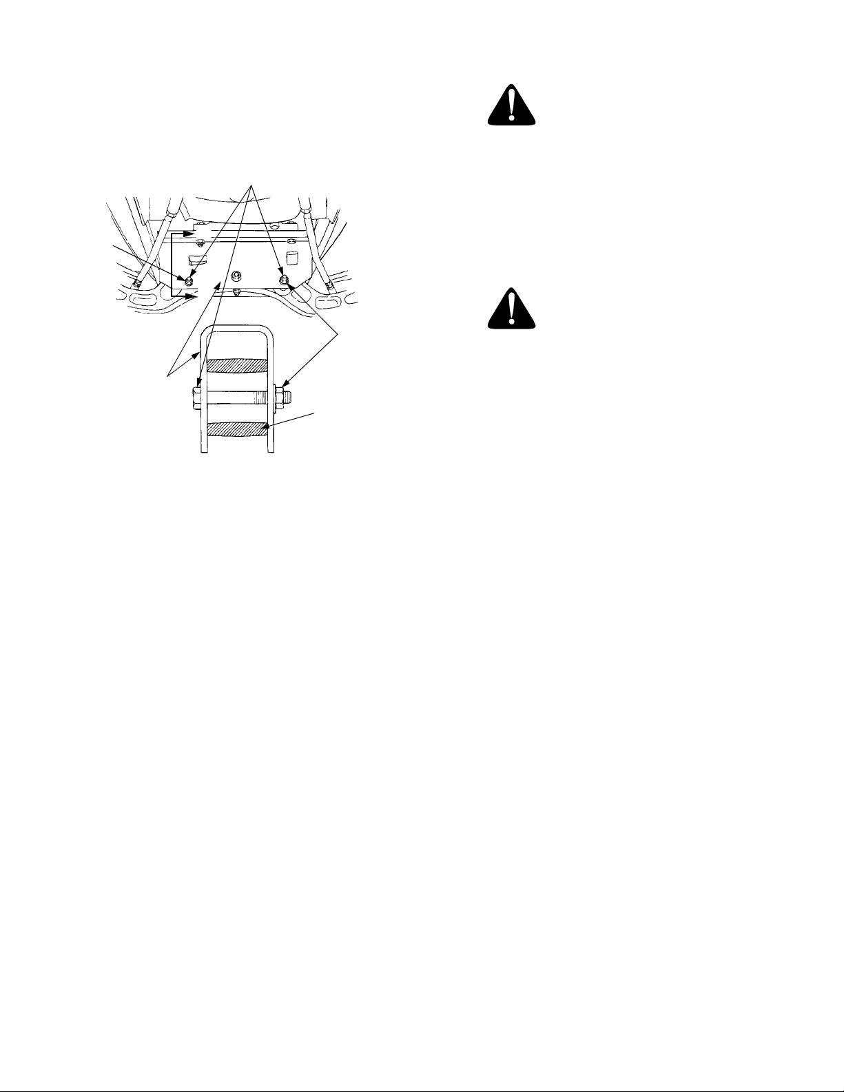
ADJUSTING LIFT ASSIST SPRING TENSION
The effort required to operate the implement lift handle
can be varied by loosening or tightening the lift assist
spring adjusting bolt (See Figure 16). The bolt can be
accessed from the rear of the tractor, inside the left
rear wheel. Turning the adjusting bolt clockwise will
decrease the manual effort required for lifting
attachments; turning counterclockwise will increase
the effort needed to lift the attachment.
LIFT ASSIST
SPRING
ADJUSTING
BOLT
Figure 16
21
Page 22
CARBURETOR ADJUSTMENTS
WARNING
When making adjustments to the carburetor
while the engine is running, disengage the PTO
clutch and engage the brake pedal lock. Keep
clear of all moving parts and be careful of all hot
surfaces.
WARNING
Carbon monoxide fumes can be fatal! Do not
make any adjustments to the carburetor in a
confined area such as a storage building. Move
the tractor outside into the air.
The carburetor is adjusted at the factory and under
normal operating conditions it will not require
readjusting. The high idle is set at the factory and
cannot be adjusted. If the engine does not operate
properly and the problem appears to be fuel system
related, check the following areas before adjusting the
carburetor: Refer to MAINTENANCE section.
• Check for fuel in fuel tank
• Check fuel cap vent for blockage
• Check fuel line for pinched or obstructed areas
• Check for fuel filter blockage
• Check for a clogged air filter
If, however, the engine is hard-starting or runs roughly
or stalls at low idle speed, it may be necessary to
adjust or service the carburetor. Minor carburetor
adjustment may also be needed to compensate for
differences in fuel, temperature or altitude.
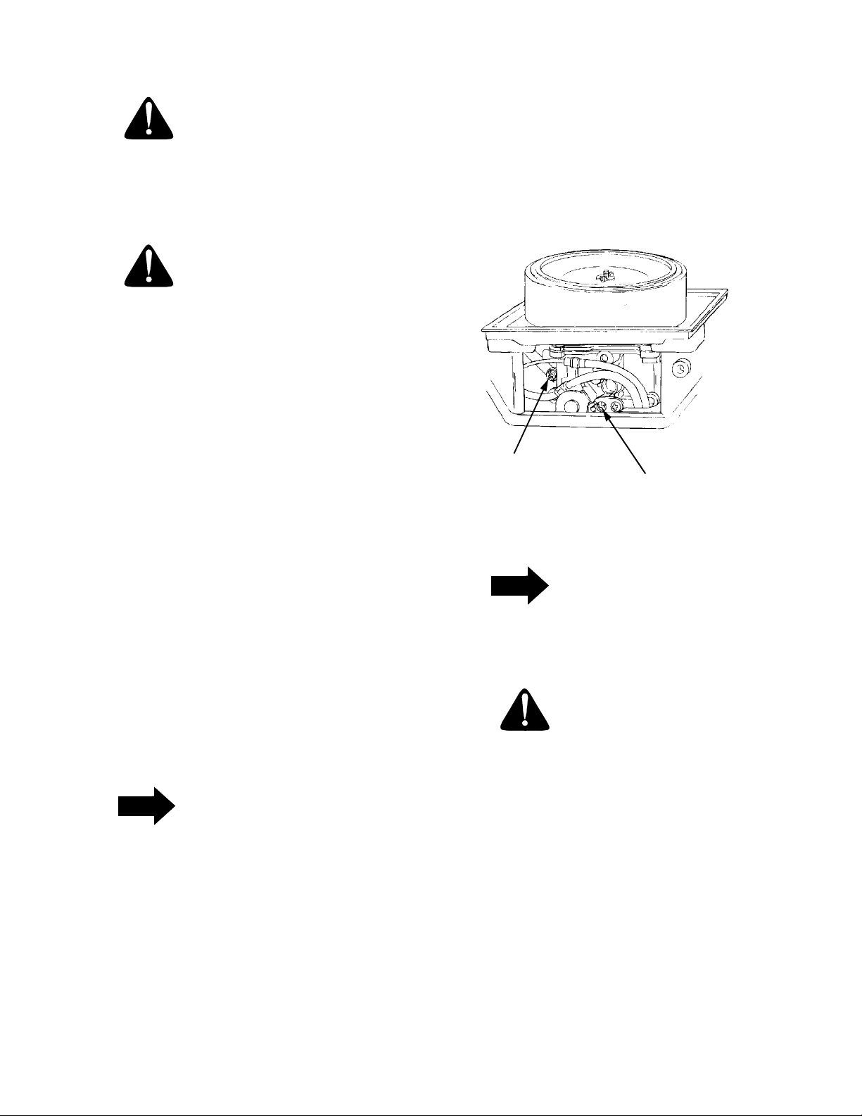
2. Idle Speed Setting: Place the throttle control into
the “idle” or “slow” position. Set the low idle speed
to 1200 rpm (± 75 rpm) by turning the low idle
speed adjusting screw in or out. Check the speed
using a tachometer (See Figure 17).
NOTE: AIR CLEANER COVER MUST
BE REMOVED TO ADJUST
CARBURETOR IDLE SPEED
IDLE SPEED
ADJUSTING SCREW
AND SPRING
IDLE FUEL ADJUSTING
NEEDLE AND SPRING
Figure 17
NOTE
The recommended low idle speed for the engine is 1200 rpm. To ensure best results when
setting the low idle fuel needle, the low idle
speed must not exceed 1200 rpm (± 75 rpm).
The air filter element and element cover must be
assembled to the carburetor when running the engine.
Adjust the carburetor idle fuel mixture in the order
stated as follows (Refer to Figure 17):
NOTE
Carburetor adjustments should be made only
after the engine has warmed up.
1. Start the engine and run at half throttle for 5 to 10
minutes to warm up. The engine must be warm
before making the final settings. Check that the
throttle and choke plates can fully open.
CAUTION
The tip of the low idle fuel adjusting needle is
tapered to critical dimensions. Damage to the
needle and the seat in the carburetor body will
result if the needle is forced.
3. Low Idle Fuel Needle Setting: Place the throttle
into the “idle” or “slow” position. Turn the low idle
fuel adjusting needle in slowly until the engine
speed decreases, and then back out approximately
3/4 turn to obtain the best low speed performance.
4. Recheck the idle speed using a tachometer.
Readjust the speed as necessary.
22
Page 23
SECTION IV. MAINTENANCE
ENGINE MAINTENANCE
Maintenance, repair, or replacement of the emission
control devices and systems, which are being done at
the customer’s expense, may be performed by any
engine repair establishment or individual. Warranty
repairs must be performed by an authorized Kohler
service outlet.
ENGINE OIL
The engine-crankcase is filled with ship-away oil. This
oil may be used for the first 5 hours of engine operation
at temperatures between 0° and 90°F. If temperatures
are not within this range, drain the oil from the oil filter
and crankcase and replace with new oil as specified in
the LUBRICATION TABLE.
To aid starting, the selection of crankcase lubricating
oils should be based on the lowest anticipated
temperatures until the next scheduled oil change.
For oil change intervals of 100 hours, the following oils
are recommended.
Ambient Temperature Viscosity (Grade SG/SH)
+32°F and Above — Cub Cadet Engine Oil S.A.E.
10W30 or S.A.E. 10W40
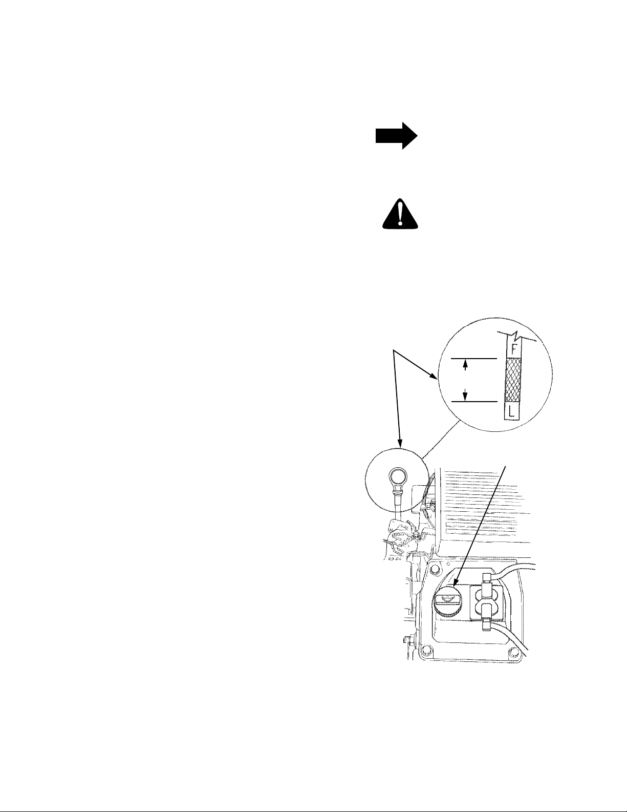
• Never operate the engine with the oil level below
the “L” mark or above the “F” mark on the dipstick.
NOTE
Check the oil level only while the engine is
stopped and the tractor is level.
CAUTION
The oil level should be checked every hour
during the first 5 hours of operation and prior to
every use thereafter.
OIL LEVEL
DIPSTICK
OPERATING
RANGE
Below +32°F — Cub Cadet Engine Oil S.A.E.
5W20 or S.A.E. 5W30*
*Synthetic Engine Oil S.A.E. 5W20 or S.A.E. 5W30 is
acceptable, up to 40°F.
CHECKING THE OIL LEVEL
Regularly checking and maintaining the engine oil level
in the crankcase cannot be overemphasized. Close
monitoring of the oil level during the first 10 hours of
operation is especially important. Referring to Figure
18, check the oil level BEFORE EACH USE as follows:
• The engine must be cool so the oil has had time to
drain into the sump of the crankcase.
• Clean the area around the oil level dipstick to prevent debris from entering the crankcase.
• Remove the dipstick and wipe it clean. Insert the
dipstick into the tube and press all the way down.
• Remove the dipstick and check the oil level.
• Always keep the oil level at or near the “F” mark on
the dipstick. If the oil is low, add oil of the proper
type up to the “F” mark. Always check the oil level
with the dipstick before adding more oil.
OIL FILLER
CAP
Figure 18
23
Page 24
ADDING OIL
CAUTION
Never overfill the engine crankcase. The engine
may overheat and/or damage may result if the
crankcase is below the “LOW” mark or over the
“FULL” mark on the dipstick.
WARNING
If the tractor has recently been operated, the
engine and surrounding areas may be hot. Use
caution not to burn yourself when removing the
side panels, draining the oil from the crankcase,
and changing the oil filter.
NOTE
For best results, fill to the “FULL” mark on the
dipstick as opposed to adding a given quantity
of oil. Always check the level on the dipstick
before adding more oil.
Refer to the LUBRICATION TABLE for information
regarding the proper type of oil to add to the
crankcase.
1. Place the tractor on a level surface and engage the
brake pedal lock. Stop the tractor engine and
remove the ignition key.
2. Clean the area around the oil level dipstick,
dipstick tube, and the oil filler cap to prevent debris
from entering the crankcase.
3. Remove the oil filler cap from the left valve cover
and SLOWLY pour in oil. Fill the crankcase until
the oil level reaches the “FULL” mark on the
dipstick (Refer to Figure 18).
4. Reinstall the oil filler cap by screwing it securely
into the valve cover.
NOTE
The oil filter should be changed at every oil
change interval. The filters can be obtained
through your Cub Cadet dealer under part
number KH-12-050-08.
Refer to the MAINTENANCE CHART and the
LUBRICATION TABLE for information regarding the
frequency of required oil changes and the quantity and
type of oil needed.
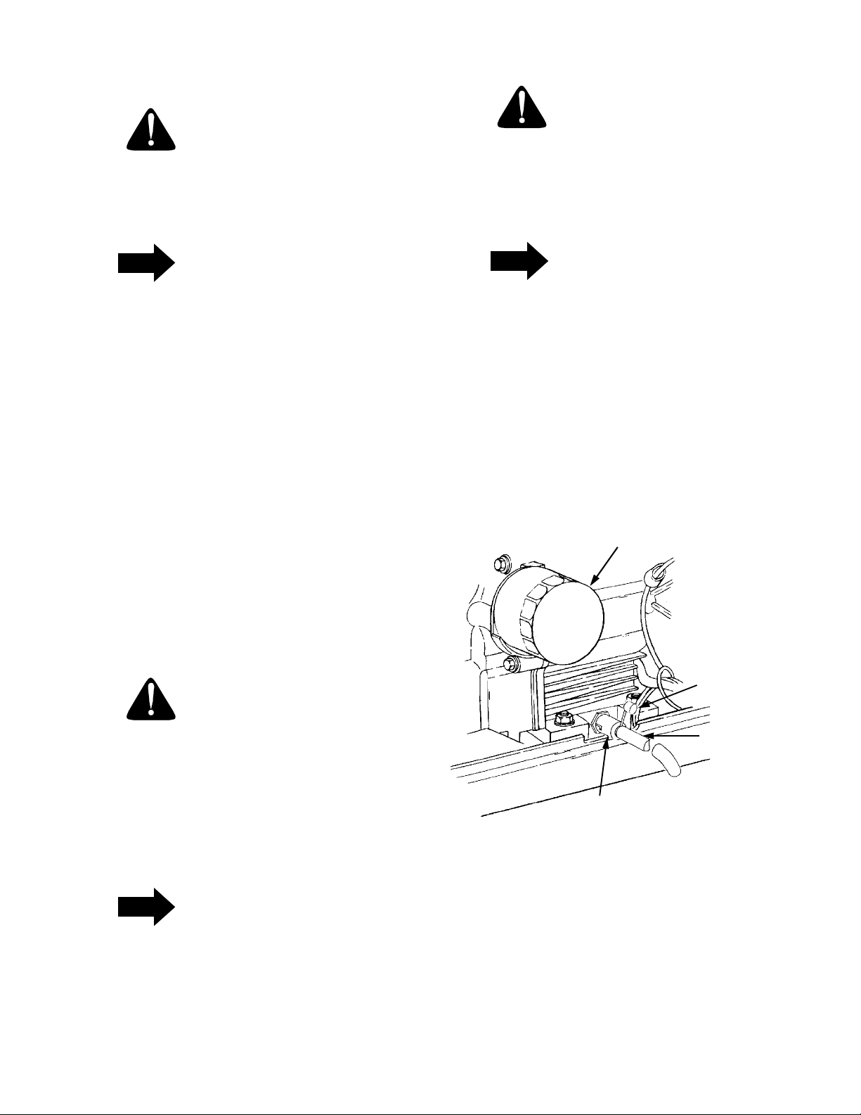
The oil filter is located behind the left side panel and is
mounted on the engine (See Figure 19).
OIL
FILTER
CAUTION
The oil filler cap MUST BE TIGHTENED
SECURELY INTO THE VALVE COVER AT
ALL TIMES WHEN THE ENGINE IS
OPERATING. Severe engine damage could
result from failure to do so.
DRAINING OIL AND REPLACING OIL FILTER
NOTE
The engine oil should be changed after the first
5 hours of operation. Then oil should be
changed after every 100 hours of operation.
PLASTIC
CAP
FLEXIBLE
TUBING
OIL DRAIN
VALVE
Figure 19
Run the engine for a few minutes to allow the oil in the
crankcase to warm up. Warm oil will flow more freely
and carry away more of the engine sediment which
may have settled at the bottom of the crankcase. Use
care to avoid burns from hot oil.
24
Page 25

While the engine oil is warm, proceed as follows:
NOTE
A 12 inch length of flexible tubing is supplied in
the owner’s manual package and should be
used to drain the engine oil.
1. Place the tractor on a level surface and engage the
brake pedal lock. Stop the tractor engine and
remove the ignition key.
FILLING THE CRANKCASE
CAUTION
Never overfill the engine crankcase. The engine
may overheat and/or damage may result if the
crankcase is below the “LOW” mark or over the
“FULL” mark on the dipstick.
2. Clean around the base of the oil filter, oil level
dipstick, dipstick tube, and the oil filler cap to
prevent debris from entering the crankcase.
3. Unseat the plastic dust cap from the engine oil
drain valve. To prevent loss of the cap, do not
remove the cap’s retaining ring from the drain
valve (Refer to Figure 19). Remove the dipstick
and oil fill cap.
4. Attach the flexible tubing (supplied in owner’s
manual package) to the drain valve. Place an
appropriate container below the open end of the
tubing to collect the old oil.
5. To open the drain valve, push it slightly inward and
turn it counterclockwise until it stops, then pull it
outward.
6. Remove the filter by turning it counterclockwise
using an automotive type filter wrench to loosen.
7. Allow the old oil to completely drain from the
engine crankcase into the container below. To
close the drain valve, push it inward, turn
clockwise until it stops and then release it.
8. Remove the flexible tubing from the drain valve.
Clean the tubing and store in a safe place for future
use.
NOTE
For best results, fill to the “FULL” mark on the
dipstick as opposed to adding a given quantity
of oil. Always check the level on the dipstick
before adding more oil.
Refer to the LUBRICATION TABLE for information
regarding the oil capacity and the proper type of oil to
pour into the crankcase.
1. Place the tractor on a level surface and engage the
brake pedal lock. Stop the tractor engine and
remove the ignition key.
2. Clean around the oil level dipstick, dipstick tube,
and the oil filler cap to prevent debris from entering
the crankcase.
3. Remove the oil filler cap from the left valve cover
and SLOWLY pour in oil. The oil capacity is
approximately 4 pints. Fill the crankcase until the
oil level reaches the “FULL” mark on the dipstick
(Refer to Figure 18).
4. Reinstall the oil filler cap by screwing it securely
into the valve cover.
9. Clean the drain valve and push the plastic dust cap
onto the valve.
10. To assure a continuous flow of oil to all critical
lubrication points within the engine, pour some
new oil into the treaded center hole of the filter and
allow time for the oil to be absorbed into the filter
material.
11. Apply a light coating of clean oil on the gasket of
the new oil filter. Thread the filter on by hand until
the gasket contacts the oil filter adapter, then
tighten the filter an additional 1/2 turn.
Refer to FILLING THE CRANKCASE and to the
LUBRICATION TABLE and refill the crankcase with
the quantity and type of oil specified.
NOTE
The oil filler cap MUST BE TIGHTENED
SECURELY INTO THE VALVE COVER AT
ALL TIMES WHEN THE ENGINE IS
OPERATING. Severe engine damage could
result from failure to do so.
5. Start the tractor engine and allow it to run for 30
seconds, then stop the engine and remove the
ignition key.
6. Check the oil level and add oil if necessary. DO
NOT OVERFILL THE ENGINE CRANKCASE.
7. Check the oil filter and drain valve for leaks.
25
Page 26

CHECKING TRANSMISSION OIL LEVEL
NOTE
Check the oil level only while the engine is
stopped and the tractor is level.
Check the oil level of the transmission case before
each use to see that it is filled to the correct level.
Before checking the transmission oil level, clean the
area around the oil fill plug/dipstick to prevent debris
from entering the transmission case. Always keep the
oil level between the “FULL” and the “ADD” marks on
the dipstick (See Figure 20). When checking the oil
level, the dipstick must be withdrawn and wiped clean,
then inserted all the way before being withdrawn for a
true reading.
Refer to the LUBRICATION TABLE for information
regarding the proper type of oil to add to the
transmission case.
1. Place the tractor on a level surface and engage the
brake pedal lock. Stop the tractor engine and
remove the ignition key.
2. Clean the area around the oil fill plug/dipstick to
prevent debris from entering the transmission
case.
3. Remove the oil fill plug/dipstick from the oil fill port
and SLOWLY pour oil into the oil fill port. Fill the
transmission case until the oil level reaches the
“FULL” mark on the dipstick (Refer to Figure 20).
4. Reinstall the oil fill plug/dipstick securely into the
oil fill port.
OPERATING
RANGE
F
A
Figure 20
ADDING TRANSMISSION OIL
CAUTION
TRANSMISSION
DIPSTICK
CAUTION
The oil fill plug/dipstick MUST BE INSTALLED
SECURELY INTO THE FILL PORT AT ALL
TIMES WHEN THE ENGINE IS OPERATING.
HYDROSTATIC DRIVE OIL FILTER
CAUTION
Never overfill the transmission case. Damage
may result if the oil level in the transmission
case is below the “ADD” mark or over the
“FULL” mark of the dipstick.
NOTE
For best results, fill to the “FULL” mark on the
dipstick as opposed to adding a given quantity
of oil. Always check the level on the dipstick
before adding more oil.
Refer to the MAINTENANCE CHART for information
regarding the frequency of the hydrostatic
transmission oil filter replacement. The filter can be
obtained through your Cub Cadet dealer under the part
number 923-3014.
Refer to the LUBRICATION TABLE for information
regarding the oil capacity and the proper type of oil to
pour into the transmission case.
1. Place the tractor on a level surface and engage the
brake pedal lock. Stop the tractor engine and
remove the ignition key.
26
Page 27

2. Clean the area around the transmission drain plug
to prevent debris from entering the transmission
case. Remove the drain plug and allow the
transmission oil to drain into a clean container
having a capacity of more than 6 quarts. Reinstall
the drain plug (Refer to Figure 21).
CAUTION
If the transmission oil is to be re-used, cover the
container holding the drained oil to prevent
contamination. Contaminated transmission oil
can damage the hydro transmission.
TRANSMISSION
OIL FILTER
Figure 22
7. Reinstall the oil fill plug/dipstick securely into the
oil fill port.
8. Start the engine and allow it to run for a few
minutes. Shut the engine off, then check for leaks
and re-check the oil level in the transmission case.
TRANSMISSION
DRAIN PLUG
Figure 21
3. Clean around the base of the transmission oil filter
and remove the filter by turning it counterclockwise
(Refer to Figure 22).
4. Apply a light coating of clean transmission oil to the
gasket of the new filter. Install the filter by turning
it clockwise, by hand, until the gasket contacts the
filter base on the transmission housing; then
tighten the filter an additional 1/2 turn.
5. Clean the area around the transmission oil fill
plug/dipstick to prevent debris from entering the
transmission case.
6. Remove the oil fill plug/dipstick from the oil fill port
and SLOWLY pour oil into the oil fill port. Fill the
transmission case until the oil level reaches the
“FULL” mark on the dipstick (Refer to Figure 20).
CAUTION
The oil fill plug/dipstick MUST BE INSTALLED
SECURELY INTO THE FILL PORT AT ALL
TIMES WHEN THE ENGINE IS OPERATING.
AIR CLEANER
Check the air cleaner daily or before starting the
engine. Check for loose or damaged components and
check the condition of the filter element. Remove any
buildup of dirt and debris in the air cleaner housing.
NOTE
Operating the engine with loose or damaged air
cleaner components will allow unfiltered air into
the carburetor; causing extensive wear and
eventual failure of the engine.
Servicing the Precleaner
Wash and re-oil the foam precleaner at 1 month
intervals or after every 10 hours of operation (more
often under extremely dusty or dirty conditions),
whichever occurs first.
1. Unfasten the air cleaner cover retaining knob and
remove the air cleaner cover (See Figure 23).
27
Page 28

1. Unfasten the air cleaner cover retaining knob and
remove the air cleaner cover (See Figure 23).
2. Remove the foam precleaner by sliding it up off the
paper element (See Figure 23).
1
Air Cleaner Cover
1.
Wing Nut
2.
Element Cover
3.
Rubber Grommet
4.
3. Remove the wing nut and element cover plate,
then lift out the paper air filter element.
2
3
4
5
4. Do not wash the paper element or use pressurized
air, as this will damage the element. Replace a
dirty, bent or damaged element. Handle new
elements carefully; do not use if the sealing
surfaces are bent or damaged.
5. When servicing the air cleaner, check the air
6
cleaner base. Make sure it is secured and not bent
or damaged. Also check the element cover for
damage or improper fit. Replace all damaged air
cleaner components.
7
6. Inspect the rubber grommet (See Figure 23) for
deterioration, cracks, and for a snug fit on the air
cleaner stud. Replace if damaged or worn.
7. Reinstall the paper element, foam precleaner,
element cover, wing nut and air cleaner cover.
Make certain the cover retaining knob is tightened
Paper Element
5.
Foam Precleaner
6.
Air Cleaner Base
7.
securely.
Properly cleaned and installed air cleaner elements
significantly contribute to prolonging engine life.
Figure 23. Air Cleaner Assembly
2. Remove the foam precleaner by sliding it up off the
paper element (See Figure 23).
3. Wash the precleaner in warm water with
detergent. Rinse the precleaner thoroughly until all
traces of the detergent are eliminated. Squeeze
out (do not wring) excess water in a dry cloth.
Allow the precleaner to air dry.
4. Saturate the foam precleaner with new engine oil.
Squeeze out all excess oil.
5. Reinstall the foam precleaner over the paper
element.
6. Reinstall the air cleaner cover and secure with the
retaining knob.
Servicing the Paper Element
Inspect the paper element before each use. Every 100
hours of operation (more often under extremely dusty
or dirty conditions) replace the element.
CLEANING ENGINE
This tractor has an air-cooled engine. Air must be able
to circulate freely through the flywheel screen, blower
housing, and cooling shrouds, and over the cooling fins
of the cylinder head and cylinder block. Regularly
check these areas for accumulated dirt and debris to
prevent engine overheating and possibly causing
extensive engine damage. Every 100 hours of
operation, remove the blower housing and cooling
shrouds to clean the cooling surfaces of the engine.
Make sure the cooling shrouds are reinstalled.
Regularly clean the outside and inside of the side
panel screens, the dash intake screen and the grille to
ensure adequate air flow for cooling the engine.
NOTE
This machine is designed to cool properly with
the side panels in place. Operating without the
panels could cause premature accumulation of
dirt and debris on the engine, resulting in
inadequate cooling.
28
Page 29

SPARK PLUG
HEADLIGHTS
Refer to SPECIFICATIONS when replacement of
head lamp bulbs is necessary.
WARNING
To avoid possible injury, be sure the engine is
off and has cooled before making any
adjustments or repairs.
NOTE
Remove all dirt from around the spark plug
before removing.
To remove the spark plugs, always use a spark plug
wrench. Check the gap after every 100 hours of
operation.
Replace a defective plug with a new plug. Set the
spark plug gap at .030 inch (See Figure 24). Tighten
the plug to 18-22 ft-lbs. See your authorized dealer for
the correct replacement plug.
SPARK PLUG
WARNING
Allow the engine and surrounding surfaces to
cool before changing the head lamp bulbs.
Replace headlight bulbs as follows: (See Figure 25)
1. Unplug the wire harness leads from the headlight
socket terminals. Note which wire connects to
each terminal before disconnecting.
2. Rotate the socket assembly as follows to remove
from the reflector housing:
• Left headlight — appoximately 1/4 turn counter-
clockwise.
• Right headlight — approximately 1/4 turn clock-
wise.
3. Push the bulb inward and turn counterclockwise to
remove from the socket.
TERMINAL
SOCKET TAB
Figure 24
FUEL FILTER
WARNING
Do not replace the fuel filter when engine is hot.
The engine is equipped with an inline fuel filter.
Visually inspect the filter periodically for a build-up of
residue inside the filter body, and for a dirty element
which can be indicated by discoloration. Replace the
fuel filter when dirty.
REFLECTOR
NOTCH
REFLECTOR
HOUSING
Figure 25
4. Align a locking post of the bulb base with the notch
in the socket, then push the bulb inward and turn
clockwise to lock
5. With the terminals pointing upward, align the tab of
the socket with the notch of the reflector. Push the
socket inward and turn as follows to lock:
• Left headlight — appoximately 1/4 turn clock-
wise.
• Right headlight — approximately 1/4 turn coun-
terclockwise.
6. Connect the wire harness leads to the appropriate
socket terminals.
29
SOCKET
Page 30

FUSES
Always use the same capacity fuse for replacement.
Refer to SPECIFICATIONS. If the electrical system
does not function, check the fuses.
To replace a fuse, pull the old fuse from the fuse holder
and install the new fuse.
MAINTENANCE OF BATTERY
The tractor is shipped with a wet battery — the battery
acid has already been added and the battery sealed.
Although the battery is maintenance free, the following
care should be taken when handling the battery and to
assure its proper life cycle.
GENERAL BATTERY INFORMATION
WARNING
a. Battery posts, terminals and related
accessories contain lead and lead
compounds. Wash Hands after handling.
b. Battery acid must be handled with great care,
as contact with it can burn and blister the skin.
It is advisable to wear protective clothing
(goggles, rubber gloves and apron) when
working with acid.
c. Should battery acid accidentally splatter into
the eyes or onto the skin, rinse the affected
area immediately with clean cold water. If
there is any further discomfort, seek prompt
medical attention.
d. If acid spills on clothing, first dilute it with clean
water, then neutralize with a solution of
ammonia/water or baking soda/water.
e. Since battery acid is corrosive, do not pour it
into any sink or drain. Before discarding an
empty electrolyte container, rinse it thoroughly
with a neutralizing solution.
f. NEVER connect (or disconnect) battery
charger clips to the battery while the charger is
turned on, as it can cause sparks.
g. Keep all sources of ignition (cigarettes,
matches, lighters) away from the battery. The
hydrogen gas generated during charging can
be combustible.
h. As a further precaution, only charge the
battery in a well ventilated area.
Always shield eyes and protect skin and clothing
when working near batteries.
DANGER
BATTERIES CONTAIN SULFURIC ACID AND
MAY EMIT EXPLOSIVE GASES. USE
EXTREME CAUTION WHEN HANDLING
BATTERIES.
KEEP BATTERIES OUT OF THE REACH OF
CHILDREN.
1. Spray the terminals and exposed wire with a
battery terminal sealer, or coat the terminals with a
thin coat of grease or petroleum jelly, to protect
against corrosion.
2. The battery should be kept clean. Any deposits of
acid should be neutralized with baking soda and
water. Be careful not to get this solution in the
cells.
3. Avoid tipping the battery. Even a “sealed” battery
will leak electrolyte when tipped.
STORAGE OF THE BATTERY
1. When storing the tractor for extended periods,
disconnect the battery cables. Removing the
battery from the unit is recommended.
2. All batteries discharge during storage. Keep the
exterior of the battery clean, especially the top. A
dirty battery will discharge itself more rapidly.
3. The battery must be stored with a full charge. A
discharged battery will freeze at a higher
temperature.
Specific Gravity Freezing Point
1.265 –71°F
1.250 –62°F
1.200 –16°F
1.150 5°F
1.100 16°F
COMMON CAUSES FOR BATTERY FAILURE
1. Overcharging
2. Undercharging
3. Loose and/or corroded connections
4. Excessive loads
5. Freezing of electrolyte
* These causes do not constitute warranty in
the event of a battery failure.
30
Page 31

BATTERY REMOVAL OR INSTALLATION
WARNING
5. Lift the battery upward and remove from the left
side of the tractor.
Battery posts, terminals and related
accessories contain lead and lead compounds.
Wash Hands after handling.
When removing the battery, disconnect the
battery cables in the following order to avoid
arcing and the resulting sparks:
Battery Removal:
1. Disconnect the Negative cable.
2. Disconnect the Positive cable.
Battery Installation:
1. Connect the Positive cable.
2. Connect the Negative cable.
To replace the battery, proceed as follows:
1. Remove the negative cable from the negative
terminal of the battery, then remove the positive
cable from the positive terminal.
2. Remove the wing nut securing the mounting rod to
the bulkhead mounting bracket (Refer to Figure
26) and pull the rod downward from the bulkhead
bracket.
HOLDDOWN
STRAP
MOUNTING
ROD
ROTATE
UPWARD
Figure 27
6. Install the new battery from the left side of the
tractor and lower into the battery tray.
7. Stretch the battery holddown strap downward
across the front of the battery and hook to the tab
below the battery tray.
WING NUT
MOUNTING ROD
Figure 26
3. Rotate the mounting rod fully upward toward the
dash panel to provide clearance for battery
removal (See Figure 27).
4. Pull downward on the bottom of the battery
holddown strap to release it from the tab beneath
the battery tray.
8. Rotate the mounting rod downward and insert
through the bottom of the hole in the bulkhead
mounting bracket (See Figure 26).
9. Install the wing nut onto the mounting rod, but do
not tighten until after the side panels are installed.
10. Connect the positive cable to the positive terminal
of the battery, then connect the negative cable to
the negative terminal.
JUMP STARTING
WARNING
Failure to use this jump starting procedure
could cause sparking, which could result in an
explosion of either battery.
1. Attach the first jumper cable from the positive
terminal of the good battery to the positive terminal
of the dead battery.
2. Attach the second jumper cable from the negative
terminal of the good battery to the FRAME OF THE
UNIT WITH THE DEAD BATTERY.
31
Page 32

TIRES
Keep the pneumatic tires properly inflated. Overinflation will cause operator discomfort. Under-inflation
will cause short tire life.
Improperly inflated tires will also affect the leveling of
the mower deck and quality of cut.
Inflate the front and rear tires as shown in the following
table:
Tire SizePounds per Square Inch
MOUNTING TIRES ON THE RIM
WARNING
Do not mount a tire unless you have the proper
equipment. Do not inflate the tire above the
recommended pressure. Do not stand over the
tire assembly when inflating. Accidental over
inflation could cause an explosive separation of
the tire and rim, which could result in serious
injury of death.
Front Tires
16 x 6.5–814
Rear Tires
23 x 9.5–12 10
Always ensure that the tire valve caps are in place and
tightened securely to prevent loss of air and to protect
the valve core and stem.
Do not overload the tractor tires by mounting
equipment on the tractor which exceeds the load
capacity of the size of the tires on the tractor.
After mounting a new or old tire on the rim, inflate it to
20 pounds (maximum) pressure to seat the tire bead
on the rim flange. Then deflate the tire to the corrrect
operating pressure.
After the first 10 hours of operation, check and
retorque the rear wheel lug nuts (both sides) to
35 ft-lbs to make sure they are seated in the rim
and are properly tightened.
NOTE
32
Page 33
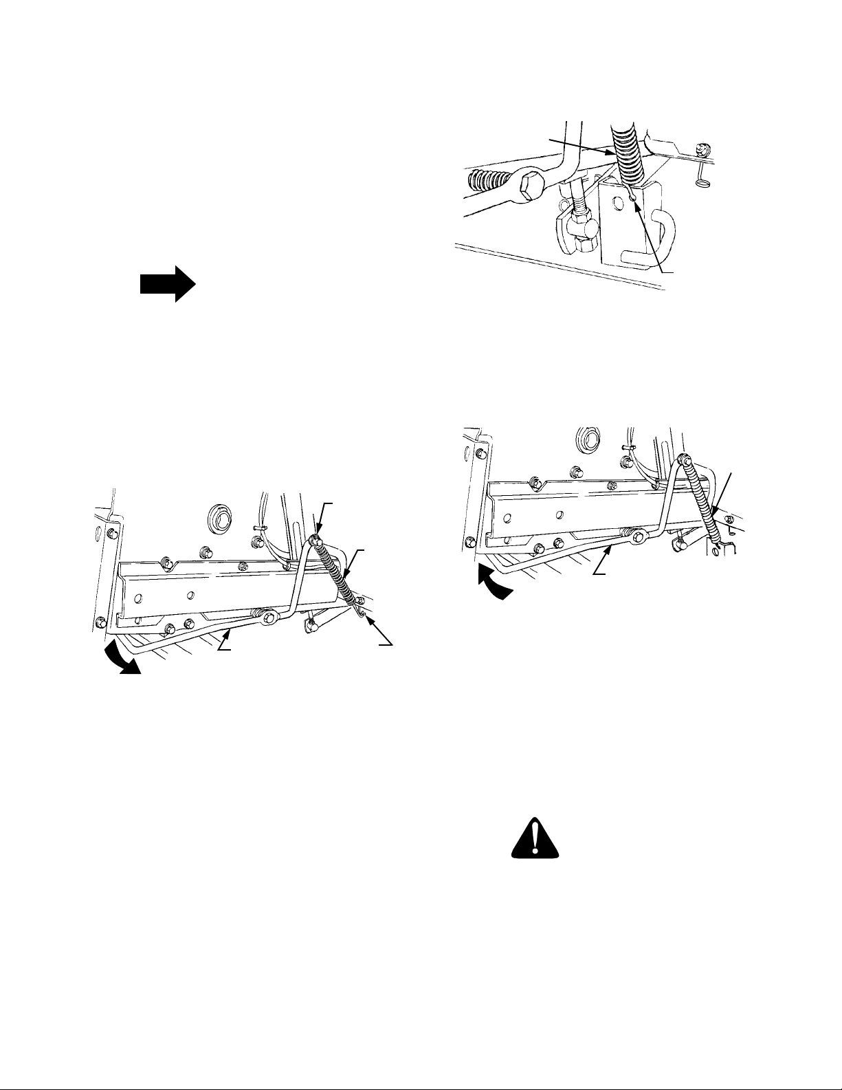
SECTION V. MOWER DECK
This section contains adjustment, removal, installation,
and maintenance information for the 44-inch mower
deck. Instructions for installation and removal of the
optional mulching plug are located at the end of this
section.
A. INSTALLING LIFT ASSIST SPRING
NOTE
The following step 1 applies only if the lift assist
spring has been factory installed. If the spring
was not installed, proceed to step 2.
1. If RH Lift Assist Spring Is Factory Installed.
From beneath the right rear fender, push the lift
assist rod down and outward to release from the
frame. Disengage the hook of the lift assist spring
from the pigtail hook (See Figure 28).
INTERNAL
COTTER PIN
LIFT ASSIST
SPRING
HOLE IN REAR
HOLE IN REAR
BRACKETDECK
BRACKETDECK
Figure 29
4. Tension the spring by pushing downward and then
inward on the rear of the lift assist rod, so that the
flange at the rearward end of the rod is inside the
tractor frame (See Figure 30).
LIFT
ASSIST
SPRING
LIFT
ASSIST
SPRING
LIFT ASSIST
ROD
PIGTAIL
HOOK
Figure 28
2. If RH Lift Assist Spring Is Not Installed.
• From underneath the fender on the right/rear side
of the tractor frame, remove the internal cotter pin
from the forward end of the rod. Refer to Figure 28.
• Slide the larger hook of the lift assist spring onto
the forward end of the rod, and reinstall the internal
cotter pin to capture the spring hook between the
rod flange and the pin. Refer to Figure 28.
3. Install the lower hook of the lift assist spring into
the hole in the right rear deck bracket (See Figure
29).
LIFT ASSIST
ROD
Figure 30
B. DECK LEVELING ADJUSTMENTS
In order to achieve even cutting, the mower deck must
be properly leveled. This leveling procedure will result
in the left and right blades having corresponding front
cutting-edge-to ground measurements within 1/16 inch
of each other. Also, the blades will each have a 1/8 to
1/4 inch downward tilt toward the front of the tractor. To
level the mower deck, proceed as follows:
WARNING
Before making any adjustments, place the PTO
switch in the “OFF” position, engage the brake
pedal lock, turn the ignition key to the “OFF”
position, and remove the key from the switch.
Disconnect the spark plug wires for additional
safety. When handling the mower deck, be
careful not to cut yourself on the sharp blades.
33
Page 34
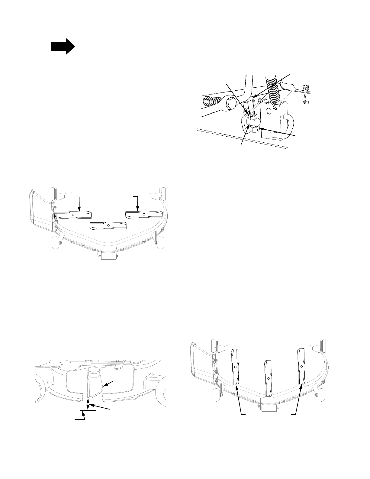
NOTE
Check the tires for proper inflation before
making a leveling adjustment. To level the deck,
the tractor and deck MUST be placed on a hard,
level surface during adjustment.
SIDE-TO-SIDE LEVELING ADJUSTMENT
1. Position the tractor and mower deck on a hard,
level surface. If necessary, reposition the front and
rear deck gauge wheels in the deck brackets to
prevent their contact with the level surface below.
Refer to GAUGE WHEEL ADJUSTMENT.
2. Raise the deck off the surface using the tractor’s
implement lift handle.
5. Lower the deck onto the hard, level surface. Sideto-side leveling is obtained utilizing the adjustment
ferrule and right hand hanger bracket (See Figure
33).
UPPER
JAM NUT
ADJUSTABLE
FERRULE
RH HANGER
BRACKET
LOWER
LOCK NUT
3. Carefully rotate the outer cutting blades so that
they are positioned perpendicular to the tractor
frame (Refer to Figure 31).
OUTER BLADES
PERPENDICULAR
TO FRAME
Figure 31
4. Measure and record the distance from the level
surface to the outer-most cutting edge of the right
blade (See Figure 32). Repeat this step for the left
blade. If the two blade heights are not within 1/16
inch, the deck must be leveled. Note whether the
right blade has the larger or smaller measurement.
If the two blade heights are within 1/16 inch,
proceed to FRONT TO BACK LEVELING
ADJUSTMENT.
Figure 33
6. Loosen the upper jam nut on the hanger bracket
and turn away from the adjustment ferrule. Turn
the lower lock nut upward (tighten) on the threads
of the hanger bracket to raise the right side of the
mower deck. Turn the lock nut down (loosen) on
the threads to lower the right side of the mower
deck (Refer to Figure 33).
7. Raise the deck from the surface and recheck the
blade measurements described in step 4. If the
blade measurements are not within 1/16 inch,
repeat steps 5 and 6.
8. Tighten the upper jam nut against the adjustment
ferrule after side-to-side leveling is completed.
FRONT TO BACK LEVELING ADJUSTMENT
1. Raise the deck of the level surface.
2. Position the mower blades so the ends of each
blade point to the front and the rear of the tractor
(Refer to Figure 34).
HARD LEVEL
SURFACE
Figure 32
BLADE
MEASURE
THIS DISTANCE
OUTER BLADES
POSITIONED FRONT TO REAR
Figure 34
34
Page 35
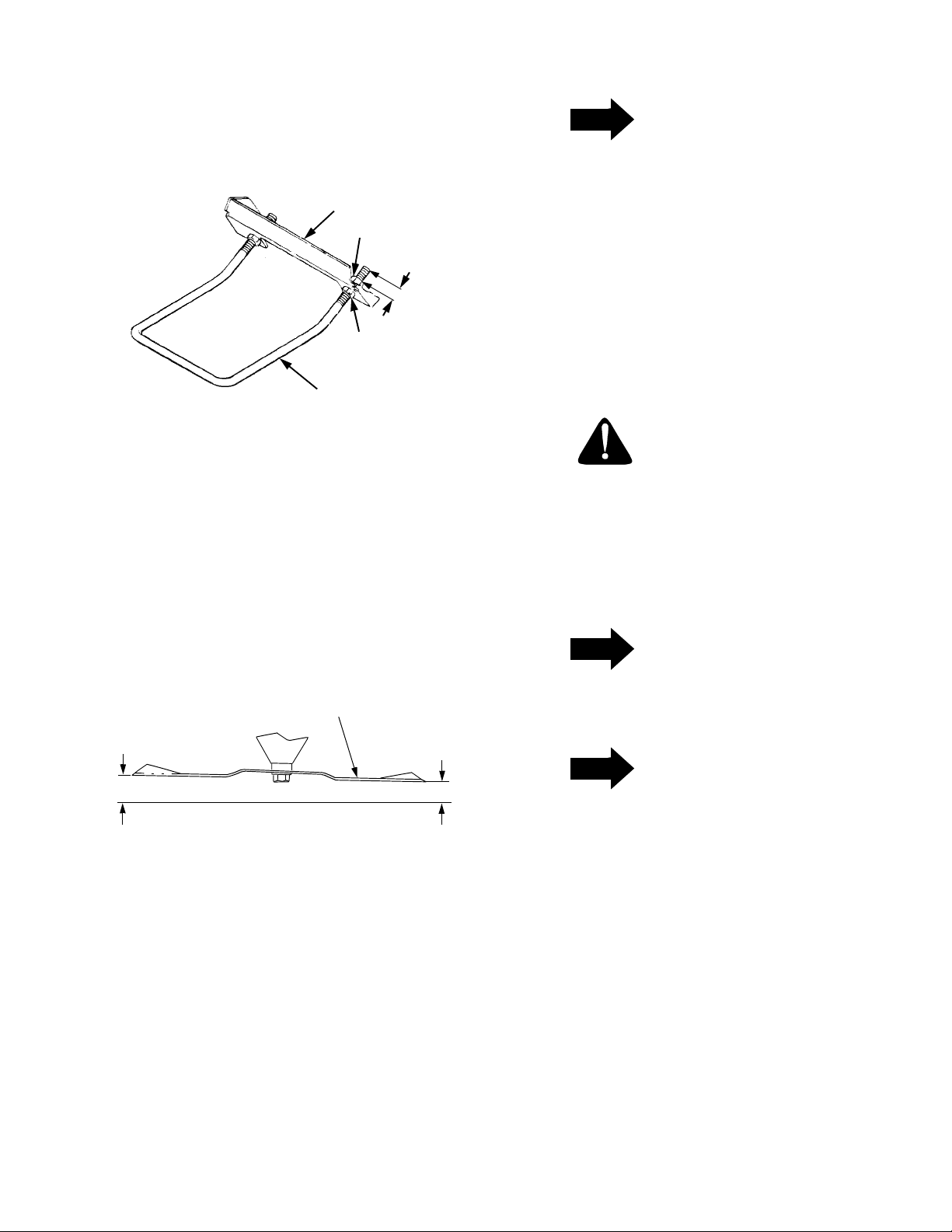
3. Initially adjust the front lift rod to allow
approximately 3/4 inch of thread to protrude
beyond both lock nuts of the front lift rod/bracket
assembly (See Figure 35).
FRONT LIFT
ROD BRACKET
LOCK NUT
3/4"
JAM NUT
NOTE
The front lift rod must be against the front of
both slots in the deck front roller bracket. If one
side of the rod is not against the front of the slot
after attaining the correct front pitch to the deck,
tighten the front lock nut on that side until the
rod just contacts the front of the slot.
8. Tighten the rear jam nuts after adjustment is
completed.
9. Connect the spark plug wires if previously
disconnected.
FRONT
LIFT ROD
Figure 35
4. Refer to Figure 36. Measure and record the
distance from the front cutting edge to the ground
(measurement A), and from the rear cutting edge
to the ground (measurement B), for the two outer
blades. The front edge measurement (A) of each
blade should be 1/8 to 1/4 inch lower than its back
edge measurement (B). If the measurements are
not within this range, adjustment of the front lift rod
is required.
REAR
CUTTING
EDGE
B
CUTTING BLADE
FRONT
CUTTING
EDGE
A
Figure 36
5. Lower the deck onto the level surface.
6. Referring to Figure 35, loosen the rear jam nuts on
the front lift rod. From the front of the tractor,
evenly turn the front lock nuts clockwise to raise
the front of the mower deck, or counterclockwise to
lower the front of the mower deck.
7. Raise the deck off the level surface. Recheck the
blade measurements described in step 4. If the
resultant measurements are not within the
specified range, repeat steps 5, 6 and 7 until the
proper measurements are obtained.
GAUGE WHEEL ADJUSTMENT
WARNING
Before making any adjustments, place the PTO
switch in the “OFF” position, engage the brake
pedal lock, turn the ignition key to the “OFF”
position, and remove the key from the switch.
Disconnect the spark plug wires for additional
safety. When handling the mower deck, be
careful not to cut yourself on the sharp blades.
NOTE
Gauge wheel adjustment should be performed
only AFTER the mower deck has been properly
leveled.
NOTE
Gauge wheels are intended to prevent scalping
of the lawn, and are not meant to be used to set
the cutting height. Do not run the deck on the
gauge wheels.
To adjust the height of the gauge wheels, place the
tractor on a firm and level surface. Refer to Figure 37,
and proceed as follows:
1. Place the tractor implement lift handle in the
normally desired mowing height setting, then
check the gauge wheels for contact or excessive
clearance with the surface below.
2. If the wheels contact the surface adjust as follows:
a. Raise the deck off the surface using the
tractor’s implement lift handle.
b. Remove the rear gauge wheels by removing
the lock nuts, shoulder screws, and flat
35
Page 36
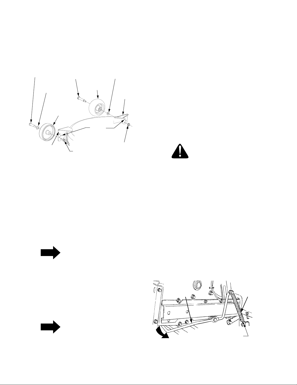
washers. Remove the lock nuts, shoulder
screws, and bell washers fastening the front
ball wheels to the deck gauge wheel brackets.
c. Again place the tractor implement lift handle in
the normally desired mowing height setting.
SHOULDER
SCREW
FLAT
WASHER
SHOULDER
SCREW
FRONT BALL
WHEEL
BELL
WASHER
GAUGE
WHEEL
BRACKET
REAR
GAUGE
WHEEL
CUTTING HEIGHT ADJUSTMENT
The mower can be set in multiple positions. NOTE: If
multiple settings are used while mowing, it may be
necessary to adjust the gauge wheels for each setting
to prevent scalping.
1. Depress the button on top of the implement lift
handle.
2. Raise or lower the lift handle to obtain the desired
mower deck cutting height.
3. Release the button when the desired mower
position is obtained. Note the numbered position of
the lift lever indicator so that the deck can be
returned to this position.
ADJUSTMENT
INDEX
HOLES
GAUGE
WHEEL
BRACKET
LOCK
NUT
LOCK
NUT
Figure 37
d. Insert the shoulder screw and flat washer with
the rear gauge wheel into the adjustment
index hole that provides approximately 1/2"
clearance between the wheel and level
surface. Secure with the lock nut.
e. Note the position of the index hole used; then
install the other rear gauge wheel and the front
ball wheels into the corresponding index hole
of the other gauge wheel brackets.
NOTE
The crowned (rounded) surface of the front bell
washers should be against the shoulder of the
shoulder screw, between the front ball wheel
and deck gauge wheel bracket.
3. If the gauge wheels have excessive clearance with
the surface below, lower the wheels to the index
hole that provides the approximate 1/2" clearance
as described above.
C. REMOVAL AND INSTALLATION OF
DECK ASSEMBLY
REMOVAL OF DECK
WARNING
Before removing the mower deck, place the
PTO switch in the “OFF” position, engage the
brake pedal lock, turn the ignition key to the
“OFF” position and remove the key from the
switch. Disconnect the spark plug wires for
additional safety.
1. Position the tractor and mower deck on a firm,
level surface. Raise the gauge wheels to their
highest setting in the gauge wheel brackets (Refer
to Figure 37).
2. Raise the deck by moving the implement lift handle
to its highest setting. From beneath the right rear
fender, release the RH lift assist rod from the
tractor frame by pushing down then outward on the
rear end of the rod. Allow the lift assist rod to raise
upward and disengage the lower hook of the lift
assist spring from the hole in the right rear deck
bracket (See Figure 38).
LIFT
ASSIST
ROD
LIFT
ASSIST
SPRING
NOTE
All gauge wheels should be installed in the
same relative adjustment index hole location in
each of the gauge wheel brackets.
REMOVE
FROM
HOLE
Figure 38
36
Page 37
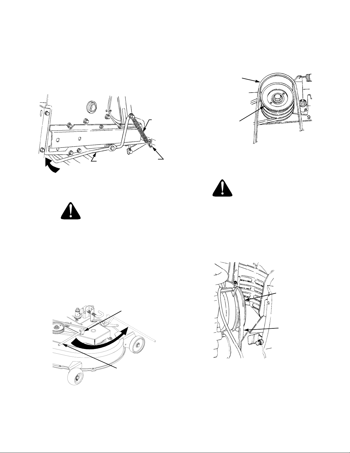
3. While lowering the rear end of the lift assist rod,
guide the lower spring hook into the pigtail hook at
the lower front of the fender (See Figure 39).
4. Tension the spring by pushing downward and then
inward on the rear of the lift assist rod, so that the
flange at the rearward end of the rod is inside the
tractor frame (See Figure 39).
6. Remove the rearward end of the PTO belt from the
upper pulley of the deck center double-pulley (See
to Figure 41). Engage the deck idler arm lever
back into its stop bracket (Refer to Figure 40).
PTO BELT
LIFT
ASSIST
SPRING
LIFT ASSIST
ROD
PIGTAIL
HOOK
Figure 39
WARNING
When handling the mower deck, be careful not
to cut yourself on the sharp blades. The deck
idler arm lever is spring loaded. Release it
slowly.
5. Lower the implement lift handle to its lowest
setting. Disengage the deck idler arm lever from its
stop bracket and release the spring tension by
rotating the lever out and rearward (Refer to Figure
40).
LEVER STOP
BRACKET
MOWER DECK
CENTER DOUBLE
PULLEY
FRONT OF DECK
Figure 41
WARNING
The exhaust system is HOT. To avoid personal
injury, allow the engine and exhaust system to
cool before proceeding with the following PTO
belt removal instructions.
7. Open the tractor hood and remove the forward end
of the PTO belt from the PTO clutch pulley (See
Figure 42).
PTO
CLUTCH
PULLEY
Figure 40
IDLER ARM
LEVER
PTO
BELT
Figure 42
8. Pass the PTO belt downward, inside the tractor
frame, until the belt is below the two tractor front
lower pulleys and pull the belt clear of the tractor
(Refer to Figure 43).
37
Page 38
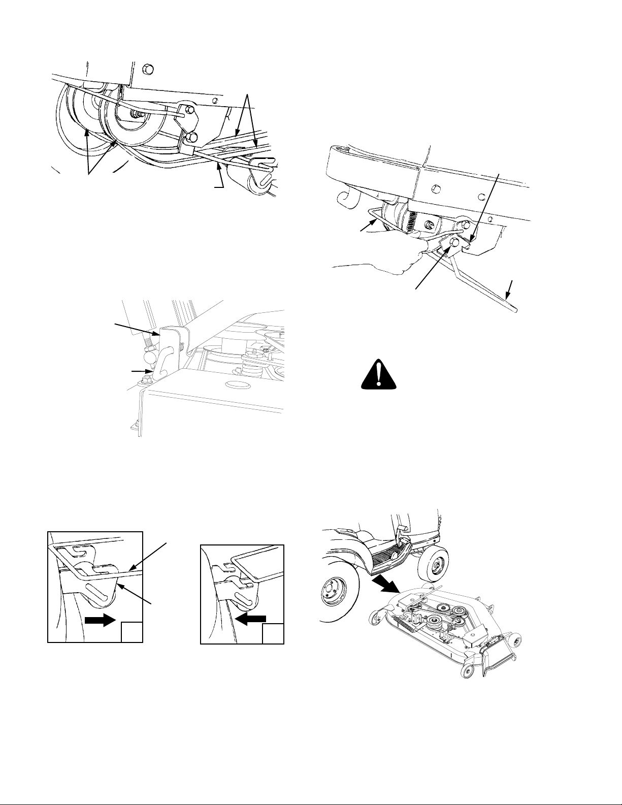
TRACTOR FRONT
LOWER PULLEYS
FRONT LIFT
ROD/BRACKET
ASSEMBLY
PTO BELT
12. From the front of the tractor, push downward and
hold the tractor quick-attach rod. Pull the front lift
rod/bracket assembly forward to release the
shoulder bolts on each side of the bracket from the
left and right tractor latch receivers. Release the
tractor quick-attach rod. Refer to Figure 46
TRACTOR
LATCH RECEIVER
(BOTH SIDES)
Figure 43
9. Pull the deck support pins outward, turn downward
and release so both spring-loaded pins are held in
the disengaged position against the outer surface
of the deck brackets (Refer to Figure 44).
REAR DECK
BRACKET
DECK SUPPORT
PIN DISENGAGED
(BOTH SIDES)
Figure 44
10. Raise the implement lift handle to its highest setting. Slide the mower deck forward, so the front lift
rod rests to the rear of, and free of, the front roller
bracket slots of the deck (Refer to Figure 45-A).
QUICK
ATTACH
ROD
FRONT LIFT
ROD/BRACKET
ASSEMBLY
SHOULDER BOLT
(BOTH SIDES)
Figure 46
CAUTION
To avoid possible equipment damage, make
sure that the tractor implement lift handle is
raised to its highest setting before sliding the
deck out from under the tractor.
13. With the tractor implement lift handle raised to its
highest setting, slide the deck to the right and out
from under the tractor (Refer to Figure 47).
FRONT LIFT ROD
FRONT
ROLLER
BRACKET
A
B
Figure 45
11. Raise the front lift rod upward and slide the mower
deck rearward. Lower the front lift rod so it rests on
the front roller bracket of the deck, forward of the
slots (Refer to Figure 45-B).
SLIDE
OUT
Figure 47
14. Connect the spark plug wires if disconnected.
38
Page 39
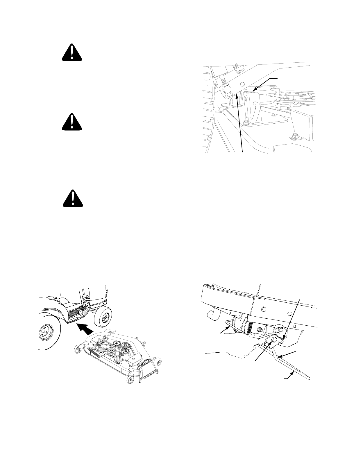
INSTALLATION OF DECK
WARNING
3. Make sure the slot in both rear deck brackets
aligns with the implement lift link on each side of
the tractor (Refer to Figure 49).
Before performing the mower deck installation,
place the PTO switch in the “OFF” position,
engage the brake pedal lock, turn the ignition
key to the “OFF” position and remove the key
from the switch. Disconnect the spark plug
wires for additional safety.
WARNING
When handling the mower deck, be careful not
to cut yourself on the sharp blades.
1. Position the tractor and mower deck on a firm,
level surface. Raise the deck gauge wheels to their
highest setting in the gauge wheel brackets (Refer
to Figure 37).
CAUTION
To avoid possible equipment damage, make
sure that the tractor implement lift handle is
raised to its highest setting before sliding the
deck under the tractor.
2. Refer to Figure 48 and position the deck on the
right side of the tractor with the front of the deck
facing toward the front of the tractor. Raise the
tractor implement lift handle to its highest setting
and slide the deck under the tractor.
SLOT IN REAR
DECK BRACKETS
(BOTH SIDES)
IMPLEMENT
LIFT LINKS
(BOTH SIDES)
Figure 49
4. Refer to Figure 50 to ensure the correct orientation
of the front lift rod/bracket assembly [form (bend)
in sides of rod point downward]. From the front of
the tractor, push downward and hold the tractor
quick-attach rod. Slide the shoulder bolts on each
side of the front lift rod/bracket assembly fully into
the left and right tractor latch receivers. Release
the tractor quick-attach rod to capture the front lift
rod/bracket assembly in the tractor latch receivers
(Refer to Figure 51).
TRACTOR
LATCH RECEIVER
(BOTH SIDES)
Figure 48
SLIDE
UNDER
QUICK
ATTACH
ROD
FORM
SHOULDER BOLT
(BOTH SIDES)
FRONT LIFT
ROD/BRACKET
ASSEMBLY
Figure 50
39
Page 40
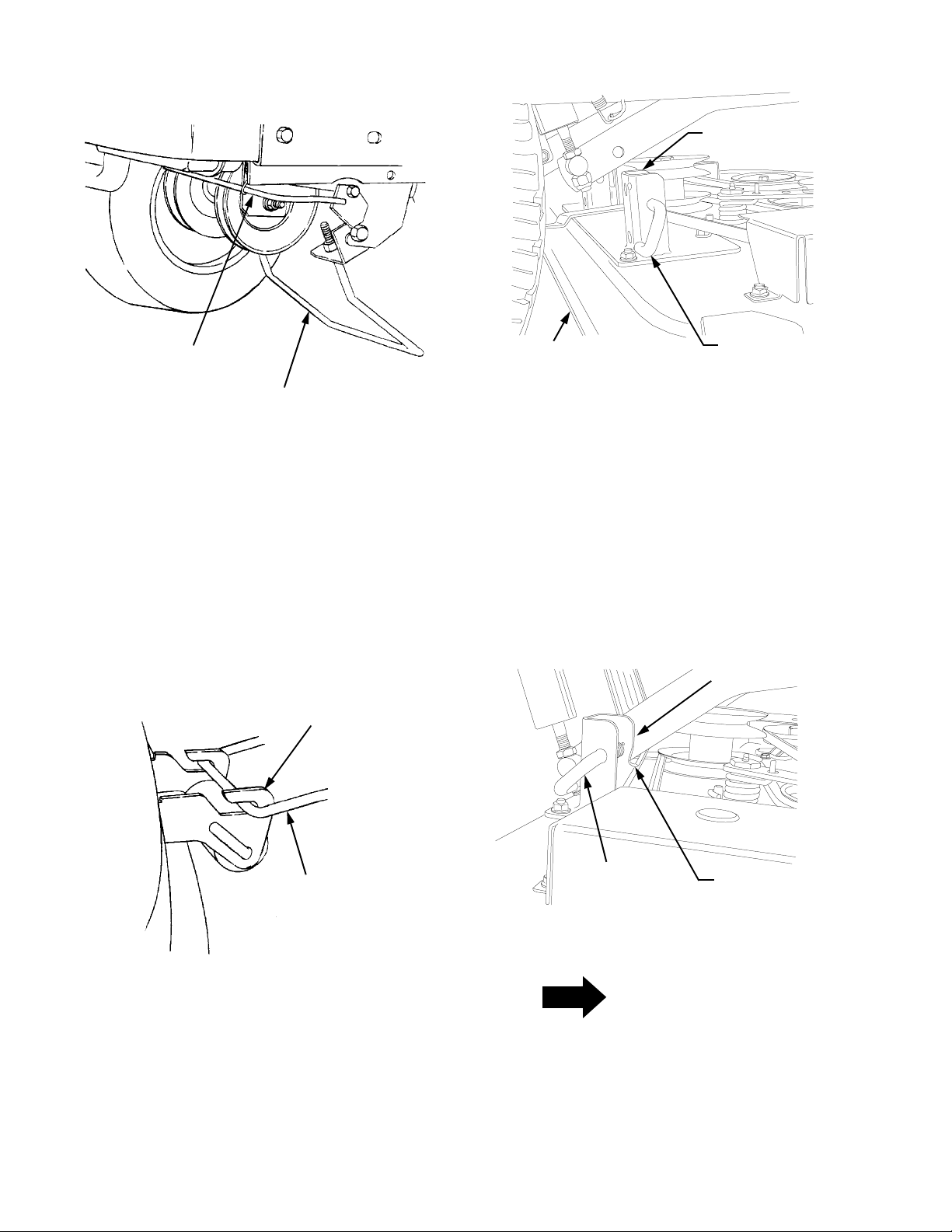
REAR DECK
BRACKET SLOTS
QUICK ATTACH ROD
FRONT LIFT ROD/
BRACKET ASSEMBLY
Figure 51
5. While holding the front lift rod up, slide the mower
deck forward until the rod aligns with both front
roller bracket slots. Lower the lift rod into the front
roller bracket slots and slide the deck rearward to
engage the lift rod fully forward in the slots of the
deck front roller bracket (Refer to Figure 52).
FRONT ROLLER
BRACKET
DECK
DECK SUPPORT
PIN DISENGAGED
Figure 53
7. Carefully guide the tractor implement lift links (left
and right) into the rear deck bracket slots (left and
right) as the tractor implement lift handle is
lowered to its lowest setting (Refer to Figure 54).
8. Pull both deck support pins outward and rotate rearward to disengage the outer surface of the rear deck
brackets. Release the pins, making certain each
deck support pin passes through the inner hole of
the rear deck bracket. The spring tension will push
the pins inward and, if aligned, through the hole in
each implement lift link (See Figure 54).
LIFT LINK HOLE
(BOTH SIDES)
FRONT
LIFT ROD
Figure 52
6. If not already done, pull the deck support pins
outward, turn downward and release so both
spring-loaded pins are held in the disengaged
position against the outer surface of the deck
brackets (Refer to Figure 53).
DECK SUPPORT
PIN ENGAGED
SLOT IN REAR
DECK BRACKET
Figure 54
NOTE
It may be necessary to lift each side of the deck
and maneuver it slightly to align the support
pins with the holes of the lift links. Make certain
the support pins are fully extended through the
lift links to prevent the mower deck from
disengaging the lift links while mowing.
40
Page 41
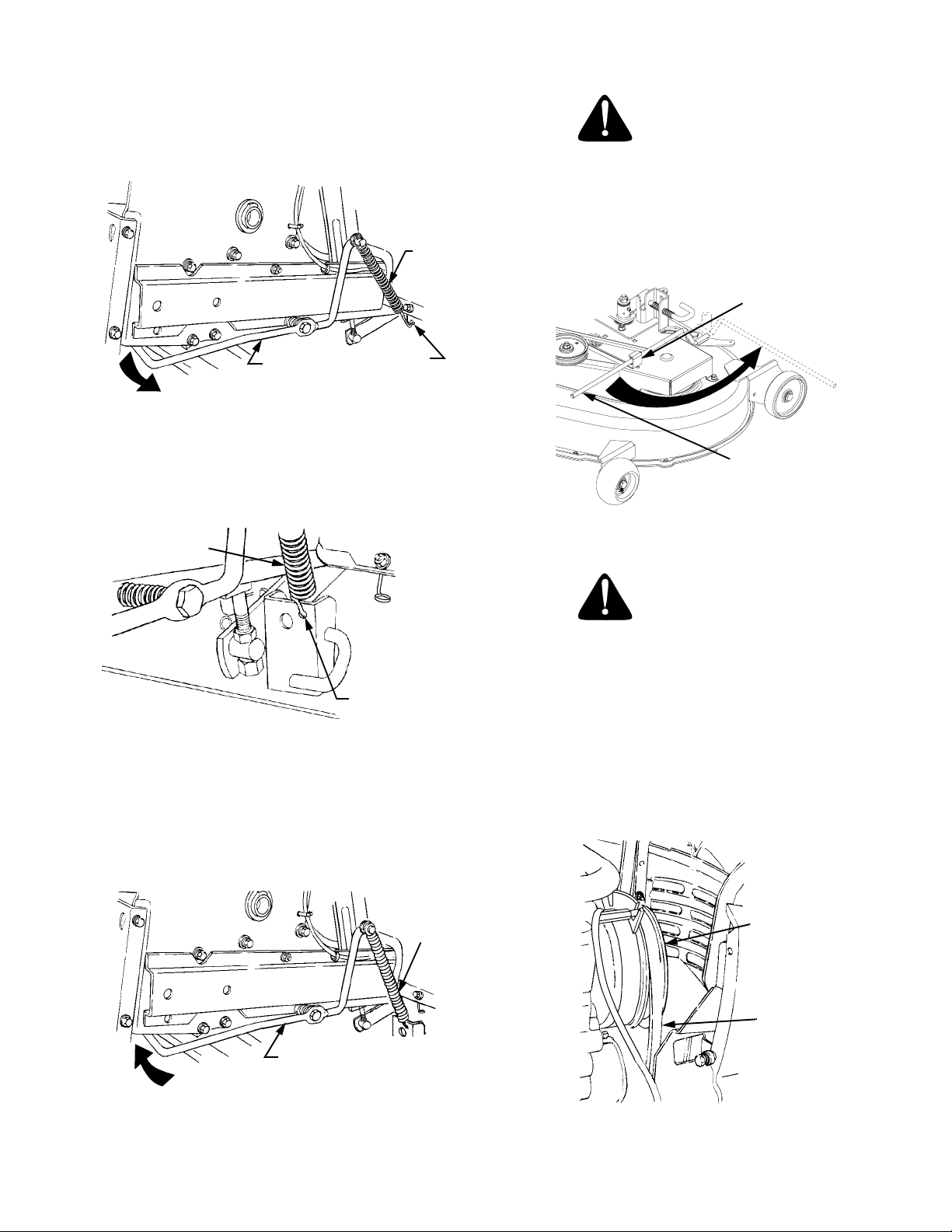
9. From beneath the right rear fender, push the lift
assist rod down and outward to release from the
frame. Disengage the hook of the lift assist spring
from the pigtail hook (See Figure 55).
LIFT
ASSIST
SPRING
WARNING
The deck idler arm lever is spring loaded.
Release it slowly.
12. Disengage the deck idler arm lever from its stop
bracket and release the spring tension by rotating
the lever out and rearward (Refer to Figure 58).
LEVER STOP
BRACKET
LIFT ASSIST
ROD
PIGTAIL
HOOK
Figure 55
10. Install the lower hook of the lift assist spring into the
hole in the right rear deck bracket (See Figure 56).
LIFT ASSIST
SPRING
HOLE IN REAR
BRACKETDECK
Figure 56
11. Tension the spring by pushing downward and then
inward on the rear of the lift assist rod, so that the
flange at the rearward end of the rod is inside the
tractor frame (See Figure 57).
IDLER ARM
LEVER
Figure 58
WARNING
The exhaust system is HOT. To avoid personal
injury, allow the engine and exhaust system to
cool before proceeding with the following PTO
belt installation instructions.
13. Install the forward end of the PTO belt on the PTO
clutch pulley by passing the belt upward inside the
front of the tractor frame. Ensure that the narrow
side of the PTO belt engages the groove of the
clutch pulley (Refer to Figure 59).
LIFT ASSIST
ROD
Figure 57
LIFT
ASSIST
SPRING
PTO
CLUTCH
PULLEY
PTO
BELT
Figure 59
41
Page 42

14. Twist the PTO belt 1/4 turn to engage the narrow
sides of the belt into the grooves of the two tractor
front-lower pulleys (Refer to Figure 60).
PTO BELT
LEVER STOP
BRACKET
IDLER ARM
LEVER
TRACTOR FRONT
LOWER PULLEYS
FRONT LIFT
ROD/BRACKET
ASSEMBLY
Figure 60
15. From the front of the tractor, push the PTO belt
through the front lift rod, then to the center of the
deck. Ensure that the forward end of the belt
remains positioned inside the front lower pulleys.
16. Install the rearward end of the PTO belt on the
upper pulley of the deck center double-pulley
(Refer to Figure 61). Ensure that the narrow side
of the belt engages the groove of the upper pulley.
PTO BELT
Figure 62
18. Connect the spark plug wires if disconnected.
D. MAINTENANCE
CLEANING AND BLADE CARE
WARNING
Before performing any maintenance, place the
PTO switch in the “OFF” position, engage the
brake pedal lock, turn the ignition key to the
“OFF” position and remove the key from the
switch to avoid accidental starting and injury.
WARNING
When servicing the mower deck, be careful not
to cut yourself on the sharpened blades.
MOWER DECK
CENTER DOUBLE
PULLEY
FRONT OF DECK
Figure 61
17. While holding the belt in position, rotate and
engage the deck idler arm lever into its stop
bracket to provide tension on the PTO belt (Refer
to Figure 62).
Clean the underside of the mower deck at the end of
the mowing season or when buildup of cut material on
the underside is noticed. Also remove the belt covers
and remove any accumulated grass clippings.
If using the mulching option, clean the underside of the
deck frequently. A buildup of grass clippings will
prevent proper mulching.
The cutting blades must be kept sharp at all times.
NOTE
Evenly sharpen the full length of the cutting
edges of the blades so that the blades remain
balanced and the same angle of sharpness is
42
Page 43

maintained. If the cutting edge of a blade has
been sharpened to within 5/8 inch of the wind
wing radius (see Figure 63), it is recommended
that new blades be installed. New blades are
available at your authorized dealer.
WIND
WING
5/8" FROM
RADIUS
After every 10 hours of operation and/or before putting
the deck into winter storage, lubricate the spindle assemblies and the spindle belt idler arm with 251H EP
grease or an equivalent No. 2 multipurpose lithium
grease. Excess grease will be expelled from the inverted upper seals of the spindle assemblies. Listen for the
muffled crackling noise of grease being expelled
through the seal to indicate the spindle assembly is fully greased. Refer to Figure 65.
Every 50 hours, or twice yearly, lubricate the double
pulley with 251H EP grease or an equivalent No. 2
multipurpose lithium grease. Do not over lubricate.
Refer to Figure 65.
Figure 63
When removing the blades, use a 1-1/8 inch wrench to
hold the hex head of the spindle bolt when loosening
the hex nut securing the blade. A block of wood may
be placed between the deck housing and the cutting
edge of the blade to assist in removal of the hex nut
securing the blade (Refer to Figure 64).
HEX NUT
WOOD BLOCK
1-1/8" WRENCH
IN POSITION
Figure 64
After replacing the blades, apply grease the exposed
threads at the bottom of the spindle bolts to prevent
rust buildup.
When replacing the blades, be sure they are installed
so that the wind wings are pointing upward toward the
top of the deck housing. Tighten the nuts to 90 to 110
ft-lbs. (122 to 149 N·m).
8
1
6
2
5
1. Spindle Belt Cover
2. Hex Nuts & Lock Washers
3. Idler Arm Lever
4. Stop Bracket
5. Front Ball Wheels
7
6
7
6
1
4
3
6. Spindle Assembly
Grease Fittings
7. Idler Arm
Grease Fitting
8. Double Pulley
5
2
Figure 65
SPINDLE DRIVE BELT REPLACEMENT
In order to replace the spindle drive belt, refer to
Figures 65 and 66 and proceed as follows:
1. Disengage the idler arm lever from its stop bracket
and rotate the lever to the outside of the deck to
release the spring tension.
2. Remove the hex nuts and lock washers that
secure the spindle belt covers to the deck.
LUBRICATION
NOTE: We do not recommend the use of a pressure
washer or garden hose to clean your unit. They may
cause damage to electrical components, spindles,
pulleys, bearings, or the engine. The use of water will
result in shortened life and reduce serviceability.
3. Remove the spindle belt covers to expose the belt.
4. Pull the movable flat idler pulley away from the
backside of the belt and slip the belt under the idler
pulley.
5. Remove the old drive belt from the spindle pulleys
and flat idler pulley.
43
Page 44

6. Carefully slip the new belt under the movable flat
idler pulley
7. Route the new belt around the spindle pulleys, the
fixed idler pulley, and the bottom pulley of the
center double pulley. Refer to Figure 66 for the
proper routing of the belt.
8. Pull the moveable flat idler pulley toward the left
side of the deck and position the backside of the
belt in the pulley. Release the pulley to tension the
belt.
9. Reinstall the spindle belt covers.
10. Engage the idler arm lever into its stop bracket.
1
5
4
1. If the mower deck has been used, clean any
buildup of grass clippings from the chute opening
of the deck housing.
2. Lift and hold the chute deflector in the upward
position (Refer to Figure 67).
3. Position the mulching plug so that the retaining lip
on the backside of the plug partially interlocks with
the lower edge of the deck chute opening; then
rotate the top of the plug upward so that the hooks
engage the deflector hinge rod (See Figure 67).
4. Push the mulching plug fully downward and lower
the chute deflector.
5. To remove the mulching plug, raise the chute
deflector and lift the mulching plug upward, then
outward to disengage from the deck. Lower the
chute deflector.
DEFLECTOR HINGE ROD
3
2
1.
Moveable Flat Idler Pulley
2.
Fixed Flat Idler Pulley
3.
Spindle Drive Belt
4.
Idler Arm Lever
5.
Center Double Pulley
Figure 66
D. INSTALLATION OF MULCHING PLUG
WARNING
Before installing the mulching plug, place the
PTO switch in the “OFF” position, engage the
brake pedal lock, turn the ignition key to the
“OFF” position.
LOWER EDGE OF
CHUTE OPENING
CHUTE
DEFLECTOR
HINGE ROD
HOOKS
CHUTE DEFLECTOR
RETAINING LIP
(ON BACKSIDE
OF PLUG)
MULCHING PLUG
Figure 67
44
Page 45

SECTION VI. OFF-SEASON STORAGE
If the machine is to be inoperative for a period longer
than 30 days, the following procedures are
recommended:
WARNING
Never store the tractor with fuel in the tank
indoors or in poorly ventilated enclosures,
where fuel fumes may reach an open flame,
spark or pilot light as on a furnace, water heater,
clothes dryer, etc.
CAUTION
Fuel left in the fuel tank during warm weather
deteriorates and will cause serious starting
problems.
To prevent gum deposits from forming inside the
engine’s carburet or and causing pos sible malfunction
of the engine, the fuel system must be either
completely emptie d, or the gasoline must be treated
with a stabilizer to prevent deterioration.
1. If using a fuel stabilizer:
a. Read the product man ufacturer’s instructions
and recommendations.
b. Add to clean, fresh gasoline the correct
amount of stabize r for the c apacity of the fuel
system.
c. Fill the fuel tank with treated fuel and run the
engine for 2-3 minutes to get stabilized fuel
into the carburetor.
2. If emptying the fuel system:
WARNING
Do not drain fue l when the engin e is hot. A llow
the engine adequate time to cool. Drain fuel into
an approved container outdoors, away from
open flame.
a. Drain any large volume of fuel from the tank by
disconnecting the fuel line from the in-line fuel
filter near the engine.
b. Reconnect the fuel line and run the engine
until it starts to fal ter, then use the choke to
keep the engine running until all fuel in the
carburetor has been exhausted.
c. Again disconnect the fuel line and drain any
remaining gasoline from the system.
3. Remove the spark plugs and pour one (1) ounce of
engine oil through the spark plug holes into the
cylinders. Crank the engine several times to
distribute the oil. Replace the spa rk plugs.
4. Clean the engine and the entire tractor thoroughly.
NOTE: We do not recommend the us e of a pressure
washer or garden hose to clea n your unit. They may
cause damage to electrical components; spindles;
pulleys; bearings; or th e engine . The use of wate r will
result in shortened life and reduce serviceability.
5. Lubricate all lubrication points.
6. Follow the battery storage instructions on page 30.
7. Protect the tir es and se at from sunligh t. Regul arly
check the tires to maintain proper inflation.
45
Page 46

SECTION VII. MOWING
MOWING
WARNING
To avoid possible injury, do not allow anyone in
the area opposite the discharge chute while
mowing. Although the area has been
supposedly cleared of foreign objects, small
objects may be picked up and discharged by
the mower.
WARNING
Never direct the discharge of material toward
bystanders or allow anyone near the machine
while in operation.
For best results it is recommended that the first two
laps should be cut with the discharge thrown towards
the center. After the first two laps, reverse the direction
to throw the discharge to the outside for the balance of
cutting. This will give a better appearance to the lawn.
Do not cut the grass too short, as the mower will tend
to scalp the grass. Short grass invites weed growth
and yellows quickly in dry weather.
Mowing should be done with the engine at full throttle.
Do not mow at high ground speed.
During certain times of the year and under some
conditions, the mower may leave streaks of uncut
grass.
Streaking may occur when attempting to mow heavy
weeds and tall grass. Under these conditions it may be
necessary to go back over the cut area a second time
to get a clean cut.
The following practices will help eliminate streaking:
1. Mow the area more often so the grass doesn’t get
too tall and heavy.
2. Operate the tractor at full throttle and slower
forward speeds.
3. Keep the blades sharp and replace the blades
when worn.
4. Follow the mowing pattern shown in Figure 68
Figure 68
MOWING WITH MULCHING OPTION
1. Do not cut wet grass. For effective mulching do
not cut wet grass. Wet grass sticks to the
underside of the deck prevention proper mulching
and dispersal of grass clippings.
2. Cut no more than 1/3 the length of the grass.
When mulching long grass, it may be necessary to
mow twice, lowering the deck another 1/3 of the
length for the second cut, and perhaps cutting in a
different pattern. Overlap the cut on each pass to
help clean up any heavy clippings left on the lawn.
3. Use a slow ground speed. Adjust ground speed
so clippings can be evenly dispersed into the
lawn.When cutting heavy grass, it may be
necessary to use a slower ground speed in order
to get a well mulched cut.
4. Always operate the tractor at full throttle. To
obtain the best cut and do the most effective job of
mulching, the engine should be run at full throttle.
5. Clean underside of deck. Be certain to clean the
underside of the deck often to avoid a buildup of
grass clippings, which will prevent proper
mulching.
46
Page 47

OPTIONAL EQUIPMENT AND ACCESSORIES
When you purchased your tractor, you probably had it
completely equipped for your particular needs at the
time. However, later you may wish to obtain optional
equipment or accessories. These items and other
allied equipment can be purchased from, and installed
by, your authorized Cub Cadet dealer.
The tractor is used for so many different types of work,
and because it is called on to operate under so many
different conditions, a variety or equipment is available
to adapt it to the requirements of the user. Refer to the
attachment guide for a complete description of
equipment and required components that can be
utilized with your tractor.
47
Page 48

MAINTENANCE CHART
Operation to
be performed
Clean grille, engine
air inlet screen, dash
intake screen and side
panel screens
Check engine oil level X
Fill fuel tank X
Change engine oil
& oil filter
Check transmission
oil level X
Replace transmission
oil filter
Clean & re-oil foam
air precleaner X
Check battery terminals
and case X
Grease front axle
pivot bolt X
Grease steering
knuckles X
Retorque rear
wheel lug nuts
Clean cooling fins &
external surfaces X
Service air cleaner
paper cartridge
Check spark plugs XX
Grease steering
gear housing X X
Grease front
wheel bearings X X
Drain fuel X
Pivot bar
adjustment bolts X
Deck spindles and
Spindle belt idler arms X X
Lube deck double pulley X X
Deck front gauge wheels X X
Lubricate all foot and
lift control pivot points X X
Before
each use
After first
5 hours
10 hours
or once
a month
More often
under dirty
conditions
X
After first
10 hours
X
After first
10 hours
X
30 hours or
three times
a season
50 hours
or twice
a season
After first
50 hours
X
100 hours
or
yearly
More often under
dirty conditions
X
Every 100 hours
thereafter
X
More often under
dirty conditions
Before
storage
NOTE
Maintenance information for optional equipment may be found in the manual which is included with that
specific piece of equipment.
48
Page 49

TROUBLE SHOOTING
Possible Cause Possible Remedy
HARD TO START
No gasoline in fuel tank or carburetor ..................... Fill the tank with gasoline. Check the fuel line, carburetor
and fuel filter.
Fuel line or carburetor clogged................................ Clean the fuel line and carburetor with a commercial
carburetor cleaner.
Fuel filter plugged .................................................... Replace.
Water in gasoline..................................................... Drain the fuel tank and carburetor. Use new fuel and dry the
spark plugs.
Choked improperly. Flooded engine ....................... Follow the starting instructions.
Defective ignition or loose wiring............................. Check the wiring, spark plugs or fuse.
Defective battery ..................................................... Check and service. Refer to “BATTERY.”
Spark plug dirty or improper gap ............................. Clean, adjust the gap to .030-inch or replace the plug.
ENGINE OPERATES IRREGULARLY OR KNOCKS
Engine incorrectly timed.......................................... *
Spark plug dirty; wrong gap or wrong type.............. Clean, reset the gap or replace.
Poor or weak spark ................................................. Check the spark plugs and wiring.
Carburetor setting incorrect..................................... Adjust. Refer to “ADJUSTMENTS.”
Poor grade fuel or water in fuel ............................... Drain and use a good grade of clean fuel.
Engine overheating ................................................. Refer to “MAINTENANCE.”
Engine valves at fault .............................................. *
Engine smokes ........................................................ Adjust the carburetor.*
Oil level rises due to gasoline in crankcase ............ *
Air filter becomes oil and fuel soaked...................... *
Engine leaks oil ....................................................... *
Misfiring ................................................................... *
Other engine problems............................................ *
Excessive oil in air cleaner ...................................... Be sure that oil dipstick is fully seated and all excess oil is
squeezed out of the pre-cleaner foam element.
PTO CLUTCH WILL NOT ENGAGE
Low or zero voltage................................................. Check battery. Charge or replace. Check charging system.
Check for worn or broken wiring or connections. Check
clutch coil resistance. Check switch.
Rotor/armature air gap too large ............................. Rotor/armature worn. Replace PTO clutch.
* See your authorized dealer.
49
Page 50

TROUBLE SHOOTING
Possible Cause Possible Remedy
LACK OF POWER
Air cleaner clogged ................................................. Service the air cleaner element. Refer to “MAINTE-
NANCE.”
Engine overload ...................................................... Reduce the load.
Engine overheated.................................................. Make sure the air intake screen, shrouding, engine fins, side
panels, dash intake screen and grille are free of
accumulated dirt and debris. Refer to “MAINTENANCE.”
Fuel tank air vent clogged ....................................... Remove obstruction from the vent in the fuel tank cap.
Air leakage between carburetor and engine ........... Remove air cleaner. Tighten the carburetor and manifold
mounting nuts. Replace any damaged parts as indicated in
“MAINTENANCE.”
Incorrect timing or faulty ignition ............................. *
Brake dragging........................................................ Adjust the brake. Refer to “ADJUSTMENTS.”
Insufficient cooling air — dirt or debris clogging the:
air intake screen • shrouds • cooling fins • side
panels • dash intake screen • or grille ..................... Keep the air intake area, side panels, grille, dash intake
screen and cooling fins clean; refer to “MAINTENANCE.”
Oil level incorrect .................................................... Engine oil level must not be over the “FULL” mark or below
the “LOW” mark on dipstick. Refer to “MAINTENANCE.”
* See your authorized dealer.
50
Page 51

LUBRICATION TABLE
Check
Point of
Lubrication
Engine crankcase Check
Hydro transmission
and transaxle with
filter
Steering knuckles
and front axle
pivot bolt
Front wheel
bearings
Steering gear
housing
Deck spindles 10 Two strokes (minimum) of the lubricator using 251H
at
Hours
before
each
use
Check
before
each
use
10 Use 251H EP grease or equivalent No. 2 multi-
30 Two strokes (minimum) of the lubricator using 251H
30 Two strokes (minimum) of the lubricator using 251H
Change
at
Capacity
Hours
100 Approx.
Add as
needed
4 pints
Approx.
6 qts
Anticipated Air Temperature
Above + 32°F Below + 32°F
Cub Cadet
Engine Oil SAE
10W30 or 10W40
Cub Cadet Drive System Fluid Plus
NOTE: Cub Cadet Drive System Fluid Plus is specially
formulated for this application. If any other oil is used
Cub Cadet will not be responsible for substandard
performance. Failures due to use of improper fluid
are not covered by warranty. For maximum protection, use Cub Cadet Drive System Fluid Plus.
purpose lithium grease and apply two strokes
(minimum) or sufficient grease to flush out old
grease and dirt.
EP grease or equivalent No. 2 multi-purpose lithium
grease.
EP grease or equivalent No. 2 multi-purpose lithium
grease.
EP grease or equivalent No. 2 multi-purpose lithium
grease.
Cub Cadet
Engine Oil SAE
5W20 or 5W30
Spindle belt
idler arm
Deck Double Pulley 50 Use 251H EP grease or equivalent No. 2 multi-purpose
Deck front gauge
wheels
Foot and lift control pivot points
10 Two strokes (minimum) of the lubricator using 251H
EP grease or equivalent No. 2 multi-purpose lithium
grease.
lithum grease. Do not over lubricate.
50 Use 251H EP grease or equivalent No. 2 multi-purpose
lithum grease.
10 Use a liberal amount of high grade lubricating oil.
51
Page 52

LUBRICATION GUIDE
WARNING
The service life and reliability of any machine depends upon the care it is given. Proper lubrication is a very
important part of that care. This lubrication schedule reflects the minimal requirements to maintain the
equipment. More frequent inspections and maintenance is preferable.
NOTE: We do not recommend the use of a pressure
washer or garden hose to clean your unit. They may
cause damage to electrical components; spindles;
pulleys; bearings; or the engine. The use of water will
result in shortened life and reduce serviceability.
Using the lubrication illustration as a guide, make
certain that all lubrication fittings are installed and
functioning.
Be sure all fittings are free from dirt and paint so the
lubricant is certain to enter the bearing.
Using a pressure lubricating gun, always force the
lubricant through the full length of each bearing until it
emerges at the end, carrying with it the worn lubricant
and any dirt that may have entered the bearing.
Miscellaneous working parts not provided with
lubrication fittings should be oiled regularly with a good
grade of lubricating oil.
Always lubricate the tractor thoroughly before taking it
to a remote location for a prolonged period of time.
Lubricant is cheap. Use plenty of it. Worn parts can be
expensive to replace.
Keep your supply of lubricating oil and grease stored in
clean containers, and covered to protect from dust and
dirt.
Keep the lubricating gun nozzle clean and wipe dirt
from the grease fittings before lubricating.
The symbols in the illlustrations indicate the method of
application and the hourly intervals to apply the
lubricant.
Use a pressure lubricating gun
and apply 251H EP grease (or
equivalent No. 2 multi-purpose
lithium grease) sufficient to flush
out the old grease and dirt.
Lubricate at the hourly intervals
indicated on the symbols.
Dipstick, use to check engine and
transmission oil before each use.
52
Page 53

LUBRICATION GUIDE
—Before Each Use
1. Engine filler cap and
dipstick
2. Transmission oil level
and fill port
—After Every 10 Hours of Operation
3. Steering knuckles (2)
(both sides)
4. Transmission oil filter NOTE: After the first 10 hours only, remove the transmission oil filter and
5. Front axle pivot bolt Use 251H EP grease or an equivalent No. 2 multi-purpose lithium grease and
6. Foot and lift control
pivot points
7. Deck spindles Use 251H EP grease or an equivalent No. 2 multi-purpose lithium grease and
8. Spindle belt idler arm Use 251H EP grease or an equivalent No. 2 multi-purpose lithium grease and
Check the oil (with the engine stopped) and add sufficient new oil to bring it to
the “FULL” mark on the dipstick. Do not overfill. Do not operate the engine if
the oil level is below the “LOW” mark on the dipstick.
Check the oil with the engine stopped. Keep the lubricant up to the “FULL”
mark on the dipstick.
NOTE: The transmission oil level and fill port services the following:
1. Rear axle
2. Hydrostatic transmission
Use 251H EP grease or an equivalent No. 2 multi-purpose lithium grease and
apply sufficient grease to flush out old grease and dirt.
replace with a new filter. Refer to “MAINTENANCE.” Change the transmission
oil filter after 50 hours and every 100 hours of operation thereafter.
apply sufficient grease to flush out old grease and dirt.
Use a liberal amount of high grade lubricating oil.
apply 2 strokes (minimum) or sufficient grease to flush out old grease and dirt.
apply 2 strokes (minimum) or sufficient grease to flush out old grease and dirt.
—After Every 30 Hours of Operation
9. Front wheel bearings Two or three strokes minimum of the lubricator using 251H EP grease or an
equivalent No. 2 multi-purpose lithium grease.
10. Steering gear
housing (2)
—After Every 50 Hours of Operation
11. Transmission oil filter NOTE: After the first 50 hours only, remove the transmission oil filter and
12. Deck front gauge
wheels
13. Deck double pulley Use 251H EP grease or an equivalent No. 2 multi-purpose lithium grease and
—After Every 100 Hours of Operation
14. Transmission oil filter Change the transmission oil filter and replace with a new filter. Refer to
15. Engine oil drain valve
and oil filter
Every 30 hours or three times a season, use 251H EP grease or an equivalent
No. 2 multi-purpose lithium grease. Apply two strokes with lubricator.
replace with a new filter. Refer to “MAINTENANCE.” Change the transmission
oil filter every 100 hours of operation thereafter.
Use 251H EP grease or an equivalent No. 2 multi-purpose lithium grease and
apply sufficient grease to flush out old grease and dirt
apply sufficient grease to maintain lubrication.
“MAINTENANCE.”
While the engine oil is warm, open the drain valve and remove the oil filter, and
drain all of the oil from the crankcase. Close the drain valve. Refer to
“MAINTENANCE,” “FILLING THE CRANKCASE” and “OIL FILTER” for
proper oil filling procedure. Refer to “LUBRICATION TABLE” for the proper
quantity and viscosity to use.
NOTE
Lubrication information for optional equipment may be found in the manual which is included with the
specific piece of optional equipment.
53
Page 54
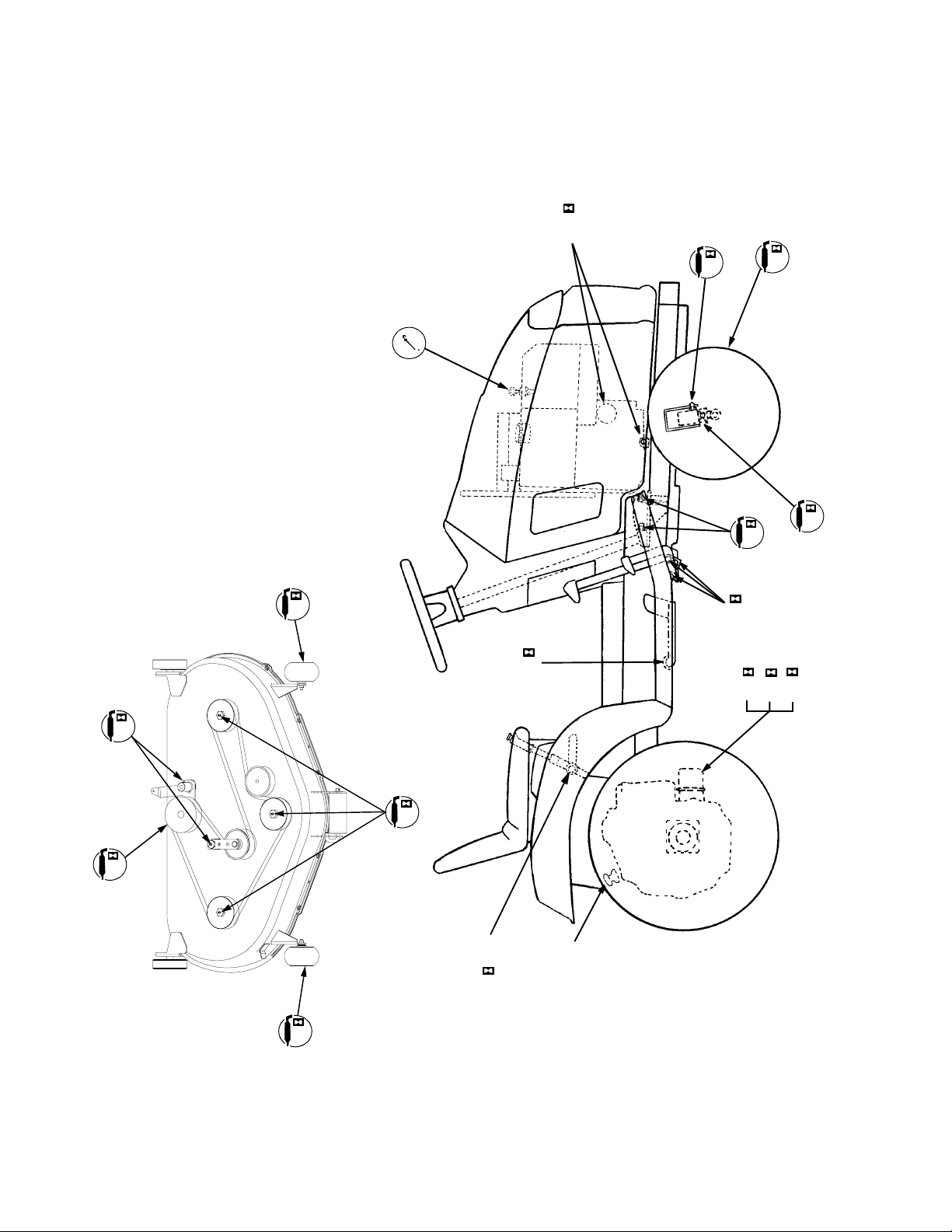
LUBRICATION GUIDE
— 15
— 8
CHECK OIL LEVEL
BEFORE EACH USE
1 —
LEFT SIDE
100
— 3
10
BOTH SIDES
— 10
— 9
BOTH SIDES
30
— 5
10
30
— 12
50
— 6
10
— 6
10
— 4
10
— 14
— 11
50
100
— 13
50
10
12 —
50
— 7
10
54
— 6
10
— 2
EACH USE
CHECK OIL
LEVEL BEFORE
Page 55

SIGHT AND HOLD THIS LEVEL WITH A VERTICAL TREE
SLOPE GAUGE
(Keep this sheet in a safe place for future reference.)
E
P
O
L
S
°
E
P
R
E
S
E
N
5
1
A
G
N
I
T
15°
A POWER POLE
A CORNER OF A BUILDING
OR A FENCE POST
R
,
E
N
I
L
D
E
T
T
O
D
N
O
D
L
O
F
WARNING
Do not mow on inclines with a slope in excess of 15 degrees (a rise of approximately 2-1/2 feet every 10 feet).
A riding mower could overturn and cause serious injury. If operating a walk-behind mower on such a slope, it is
extremely difficult to maintain your footing and you could slip, resulting in serious injury.
Operate RIDING mowers up and down slopes, never across the face of slopes.
USE THIS PAGE AS A GUIDE TO DETERMINE SLOPES WHERE YOU MAY NOT OPERATE SAFELY.
55
Operate WALK-BEHIND mowers across the face of slopes, never up and down slopes.
Page 56

56
Page 57

SPECIFICATIONS
CAPACITIES
Fuel Tank ........................................................................
Crankcase (approximately) .............................................
Transmission Case (approximately) ................................
HYDROSTATIC DRIVE
Speed: Forward................................................................
Reverse ................................................................
ENGINE
Make and Model ................................... ...........................
Horsepower ..... .................................. ..............................
Cylinders .........................................................................
Bore .............. .................. ................... ................... ...........
Stroke .............. .................................. ..............................
Displacement (c ub ic inch e s) ............. ... ... ... .....................
Engine Speed (governed)
Low Speed ...................................................................
High Speed (no load) ..................... ... ... ... ... ... ...............
Ignition .......... ............... ................... .................. ...............
Spark Plug Gap (Cub Cadet No. 759-3336) ....................
ELECTRICAL SYSTEM
System Voltage .. ... ... ... ... ... ............................ ... .... ...........
Battery ............. .................................. ..............................
Alternator ...... .................. ................... ................... ...........
Fuse (auto type) ..............................................................
Head Lamp Bulb ..............................................................
BRAKES ............................................................................
TIRE SIZES
Front ...............................................................................
Rear .............. ............................ ... ............................ ... ... ..
DIMENSIONS
Tread:
Front with 16 x 6.5-8 tires .............................................
Rear with 23 x 9.5-12 tires ...........................................
Wheelbase ......................................................................
Length, over all ............ ... ... ... .... ............................ ... ........
Width, over all (w/ mower deck - chute up) .....................
Height, over all (to top of steering wheel) ........................
Ground Clearanc e ............. ... .... ............................ ... ........
Turning Radius ................................................................
2518
2-1/8 gallons
4 pints
6 qts.
0 to 6 mph
0 to 3 mph
Kohler Command
20 HP
2
3.03 in.
2.64 in.
38.1
1200 RPM
3600 RPM ± 75
Battery
.030 in.
12 volt neg. ground
725-1706
15 amp regulated
25 amp
725-0963
Internal expanding
16 x 6.5-8
23 x 9.5-12
31.5 in.
30.25 in.
47.00 in.
72.00 in.
49.00 in.
43.00 in.
6.00 in.
28.0 in.
Specifications are subject to change without notice.
57
Page 58

CUB CADET LLC
MANUFACTURER’S ONE YEAR LIMITED WARRANTY
(COMMERCIAL USE)
The limited warranty set forth below is given by CUB CADET
LLC (“CUB CADET”) with respect to new merchandise
purchased and used in the United States, its possessions and
territories.
CUB CADET warrants this product against defects in material
and workmanship for a period of one
users, commencing on the date of original purchase and will,
at its option, repair or replace, free of charge, any part found
to be defective in material or workmanship. This limited
warranty shall only apply if this product has been operated
and maintained in accordance with the Operator’s Manual
furnished with the product, and has not been subject to
misuse, abuse, neglect, accident, improper maintenance,
alteration, vandalism, theft, fire, water or damage because of
other peril or natural disaster.
Batteries and belts are subject to separate terms as follows:
a. Batteries have a one-year prorated limited warranty
with 100% replacement during the first three
months. After three months, the battery replacement
credit is based on the months remaining in the
twelve (12) month period dating back to the original
date of sale. Any replacement battery will be
warranted only for the remainder of the original
warranty period.
b. All belts are covered by a one (1) year limited
warranty against defects in material and
workmanship.
HOW TO OBTAIN SERVICE: Warranty service is available,
WITH PROOF OF PURCHASE
AUTHORIZED CUB CADET DEALER. To locate the dealer
in your area, please check for a listing in the Yellow Pages or
contact CUB CADET by calling 1-877-282-8684 or writing to
P.O. Box 361131, Cleveland, Ohio 44136-0019. You may
also log on to our Web site at www.cubcadet.com.
(1) year for commercial
, THROUGH YOUR LOCAL
This limited warranty does not provide coverage in
the following cases:
a. Routine maintenance items such as lubricants, fil-
ters, blade sharpening and tune-ups, or adjustments
such as brake adjustments, clutch adjustments or
deck adjustments; and normal deterioration of the
exterior finish due to use or exposure.
b. Normal wear parts or components, including blades,
blade adapters, grass bags, rider deck wheels,
seats, snow thrower skid shoes, shave plates and
tires.
c. CUB CADET does not extend any warranty for
products sold or exported outside of the United
States of America, its possessions and territories,
except those sold through CUB CADET’S
authorized channels of export distribution.
No implied warranty, including any implied warranty of
merchantability or fitness for a particular purpose,
applies after the applicable period of express written
warranty above. No other express warranty or
guaranty, whether written or oral, except as mentioned
above, given by any person or entity, including the
dealer, with respect to any product shall bind CUB
CADET. During the period of the Warranty, the
exclusive remedy is repair or replacement of the
product as set forth above. (Some states do not allow
limitations on how long an implied warranty lasts, so the
above limitation may not apply to you.)
The provisions as set forth in this Warranty provide
the sole and exclusive remedy arising from the sale.
CUB CADET shall not be liable for incidental or
consequential loss or damages including, without
limitation, to any claim for loss of profits, loss of
savings or revenue, loss of the use of the equipment or
any associated equipment, facilities or service,
downtime, the claims or costs of third parties including
customers, and injury to property, and further
including expenses incurred for substitute or
replacement lawn care services, for transportation or
for related expenses, or for rental expenses to
temporarily replace a warranted product. (Some states
do not allow the exclusion or limitation of incidental or
consequential damages, so the above exclusion may not
apply to you.)
In no event shall recovery of any kind be greater than the
amount of the purchase price of the product sold. Alteration
of the safety features of the product shall void this Warranty.
You assume the risk and liability for loss, damage, or injury to
you and your property and/or to others and their property
arising out of the use or misuse or inability to use the product.
This limited warranty shall not extend to anyone other than
the original purchaser or original lessee.
How State Law Relates to this Warranty: This limited
warranty gives you specific legal rights, and you may also
have other rights which vary from state to state.
58
Page 59

CUB CADET LLC
MANUFACTURER’S LIMITED WARRANTY
(RESIDENTIAL USE)
The limited warranty set forth below is given by CUB CADET
LLC (“CUB CADET”) with respect to new merchandise
purchased and used in the United States, its possessions and
territories.
CUB CADET warrants this product against defects in material
and workmanship for a period of two (2) years for residential
users, (one (1) year for commercial users), commencing on the
date of original purchase and will, at its option, repair or
replace, free of charge, any part found to be defective in
material or workmanship. This limited warranty shall only apply
if this product has been operated and maintained in
accordance with the Operator’s Manual furnished with the
product, and has not been subject to misuse, abuse, neglect,
accident, improper maintenance, alteration, vandalism, theft,
fire, water or damage because of other peril or natural disaster.
Batteries and belts are subject to separate terms as follows:
a. Batteries have a one-year prorated limited warranty
with 100% replacement during the first three months.
After three months, the battery replacement credit is
based on the months remaining in the twelve (12)
month period dating back to the original date of sale.
Any replacement battery will be warranted only for
the remainder of the original warranty period.
b. All belts are covered by a one (1) year limited
warranty against defects in material and
workmanship.
3 Year Limited Warranty - PTO Clutch
CUB CADET warrants the power take off (“PTO”) clutch and
mounting hardware against defects in material and
workmanship for a period of three (3) years
products manufactured after August 1, 1997 for residential
users, commencing on the date of original purchase or lease
and CUB CADET will, at its option, repair or replace
charge, any PTO clutch or mounting hardware found to be
defective in material or workmanship provided this product
has been operated and maintained as set forth above.
for Series 2000
, free of
5 Year/500 Hour Limited Warranty
CUB CADET warrants the frame, front cast iron pivot axle and
drive shaft on Series 2000 and 3000 models against defects
in material and workmanship for a period of five (5) years or
500 hours, whichever occurs first, for residential users,
commencing on the date of original purchase or lease and
CUB CADET will, at its option, repair or replace
charge, any part found to be defective in material or
workmanship provided this product has been operated and
maintained as set forth above. In addition to any other reason
set forth herein, CUB CADET may deny warranty coverage if
the hour meter, or any part thereof, is altered, modified,
disconnected or otherwise tampered with.
HOW TO OBTAIN SERVICE: Warranty service is available,
WITH PROOF OF PURCHASE
AUTHORIZED CUB CADET DEALER. To locate the dealer in
your area, please check for a listing in the Yellow Pages or
contact CUB CADET by calling 1-877-282-8684 or writing to
P.O. Box 361131, Cleveland, Ohio 44136-0019. You may also
log on to our Web site at www.cubcadet.com.
, THROUGH YOUR LOCAL
, free of
This limited warranty does not provide coverage in
the following cases:
a. Routine maintenance items such as lubricants, filters,
blade sharpening and tune-ups, or adjustments such
as brake adjustments, clutch adjustments or deck
adjustments; and normal deterioration of the exterior
finish due to use or exposure.
b. CUB CADET does not extend any warranty for
products sold or exported outside of the United
States of America, its possessions and territories,
except those sold through CUB CADET’s authorized
channels of export distribution.
c. Normal wear parts or components, including blades,
blade adapters, grass bags, rider deck wheels,
seats, snow thrower skid shoes, rubber auger
spirals, shave plates and tires.
No implied warranty, including any implied warranty of
merchantability or fitness for a particular purpose,
applies after the applicable period of express written
warranty above as to the parts as identified. No other
express warranty or guaranty, whether written or oral,
except as mentioned above, given by any person or
entity, including the dealer, with respect to any product
shall bind CUB CADET. During the period of the
Warranty, the exclusive remedy is repair or replacement
of the product as set forth above. (Some states do not
allow limitations on how long an implied warranty lasts, so
the above limitation may not apply to you.)
The provisions as set forth in this Warranty provide the
sole and exclusive remedy arising from the sales. CUB
CADET shall not be liable for incidental or consequential
loss or damages including, without limitation, expenses
incurred for substitute or replacement lawn care
services, for transportation or for related expenses, or
for rental expenses to temporarily replace a warranted
product. (Some states do not allow the exclusion or
limitation of incidental or consequential damages, so the
above exclusion or limitation may not apply to you.)
In no event shall recovery of any kind be greater than the
amount of the purchase price of the product sold. Alteration
of the safety features of the product shall void this Warranty.
You assume the risk and liability for loss, damage, or injury
to you and your property and/or to others and their property
arising out of the use or misuse or inability to use the
product.
This limited warranty shall not extend to anyone other than the
original purchaser or original lessee.
How State Law Relates to this Warranty: This
limited warranty gives you specific legal rights, and you may
also have other rights which vary from state to state.
59
Page 60

MAINTENANCE PARTS CHART
MODEL 2518 SERIES 2500 20 HP KOHLER
ENGINE OIL
AIR FILTER
CARTRIDGE
PRE-CLEANER
ENGINE OIL FILTER
SPARK PLUG
TRANSMISSION OIL
FILTER
FOAM
Engine Oil Requirements approx. . . 4 pints Part No.
Cub Cadet engine oil
Ambient temperature viscosity (Grade SG or SH)
Above +32°F SAE 10W30 or 10W40
Below +32°F SAE 5W20 or 5W30
Air Filter Requirements Part No.
Clean air filter per instructions
in your Operator’s Manual . . . .
under Maintenance - Air cleaner.
Engine Oil Filter Requirements Part No.
Change every 100 hours KH-12-050-08
Gap Requirements Part No.
.030 inch gap 759-3336
Oil Filter Requirements Part No.
737-3030A (10W30)
737-3049 (5W30)
Cartridge
KH-47-083-03
Foam
Pre-cleaner
KH-24-083-02
Change every 100 hours 923-3014
TRANSMISSION
OIL
BELTS
BLADES Original Equipment Blade Part No.
Transmission Oil Requirements approx. . . 6 qts Part No.
Check before each use
1 quart
1 gallon
Deck Blade Belt Tractor to Deck Belt
ModelPart No.Model Part No.
44" Deck 954-3039 44" Deck 954-3068
44" Mower Blade 759-3939 (3)
Optional Blade Part No.
44" Hi-Lift Mower Blade 759-3949
737-3120
737-3121
 Loading...