

Page 1

Professional Shop Manual
2000 Series Tractors
(2011 Model year and Newer)
NOTE: These materials are for use by trained technicians who are experi enced in the service and repair of outdo or power
equipment of the kind described in this publication, and are not intende d for use by untrained or inexperienced individuals.
These materials are intended to provide supplemental information to assist the trained technician. Untrained or inexperienced individuals should seek the assistance of an experie nced and trained professio nal. Read, understand, and follow all
instructions and use common sense when working on powe r e quip ment. T his includes the contents of the product’s Operators Manual, supplied with the equipment. No liability can be accepted for any inaccuracies or omission in this publication,
although care has been taken to make it as complete and accurate as possible at the time of publication. However, due to
the variety of outdoor power equipment and continuing product changes that occur over time, updates will be made to these
instructions from time to time. Therefore, it may be necessary to obtain the latest materials before servicing or repairing a
product. The company reserves the right to make changes at any time to this publication without prior notice and without
incurring an obligation to make such changes to previously published versions. Instructions, photographs and illustrations
used in this publication are for reference use only and may not depict actual model and component parts.
© Copyright 2011 MTD Products Inc. All Rights Reserved
MTD Products Inc. - Product Training and Education Department
Page 2

Page 3

Table of Contents
Chapter 1: Introduction
Professional shop manual intent ........................................................................1
Fasteners ...........................................................................................................1
Assembly ...........................................................................................................3
Description of the 2000 series tractor ................................................................3
Model and Serial Numbers ................................................................................ 4
Chapter 2: Engine Related Parts
Muffler ................................................................................................................5
Fuel tank removal/replacement ..........................................................................6
Throttle cable adjustment .................................................................................10
Choke cable adjustment ..................................................................................10
Choke and Throttle levers and cables .............................................................11
Engine removal/installation ..............................................................................13
Chapter 3: Brakes
Brake adjustment .............................................................................................17
Brake puck/rotor replacement ..........................................................................19
Brake shaft assembly .......................................................................................21
Brake rod adjustment 2.......................................................................................3
Chapter 4: Body
What is covered by this chapter .......................................................................25
Hood ................................................................................................................25
Hood components: side vent removal ..............................................................26
Hood components: Headlight removal .............................................................27
Hood components: grille removal ....................................................................28
Hood components: pivot bracket removal ........................................................30
Fender and running board ...............................................................................31
Dash Panel ......................................................................................................35
Chapter 5: Drive system
Transmission fluid filter ....................................................................................39
Transmission fluid change ............................................................................... 40
Drive shaft ........................................................................................................41
Hydro neutral control adjustment..................................................................... 42
Transmission removal/replacement .................................................................44
Forward drive pedal shaft ................................................................................48
Reverse drive pedal shaft ................................................................................ 50
Transmission Disassembly.............................................................................. 52
Transmission Assembly ...................................................................................61
I
Page 4

Chapter 6A: Manual Steering
Steering alignment ...........................................................................................67
Front wheels ....................................................................................................69
Front wheel bearings .......................................................................................70
Axles ................................................................................................................71
Steering sector gear and steering pinion gear .................................................72
Steering shaft ...................................................................................................74
Pivot bar ...........................................................................................................78
Steering housing ..............................................................................................79
Greasing the steering housing .........................................................................80
Chapter 6B: Electronic Power Steering
Rubber Torsion Coupling................................................................................. 81
EPS Module .....................................................................................................81
EPS motor & gearbox ......................................................................................82
Troubleshooting the EPS................................................................................. 83
EPS removal/replacement ...............................................................................88
Chapter 7: electrical system
Introduction ......................................................................................................93
RMC Module ....................................................................................................93
Key switch ........................................................................................................94
RMC Module ....................................................................................................96
To identify a faulty RMC module: .....................................................................97
PTO Switch ......................................................................................................99
Brake Switch ....................................................................................................99
Reverse Safety Switch ...................................................................................100
Seat Safety Switch .........................................................................................100
Seat circuit (GTX2154LE) ..............................................................................101
Starter solenoid ..............................................................................................102
PTO Relay ..................................................................................................... 102
Start Circuit ....................................................................................................103
Run Circuit .....................................................................................................106
Run Circuit / Reverse Caution mode .............................................................107
Engine shut-down circuits ..............................................................................108
Charging circuit ..............................................................................................109
PTO Circuit ....................................................................................................114
Reverse Mower Control (RMC) circuit operation ........................................... 116
Deck lift circuit ................................................................................................118
Electrical diagnosis ........................................................................................119
Electronics .....................................................................................................119
Electrical environment: AC Vs. DC ................................................................ 120
Ohm’s Law .....................................................................................................121
Kirchhoff’s current law ....................................................................................121
Kirchhoff’s voltage law . .................................................................................. 122
How the system is wired together ..................................................................122
Types of circuits .............................................................................................123
Series .............................................................................................................123
II
Page 5

Parallel ...........................................................................................................123
Series/parallel ................................................................................................124
Shorts .............................................................................................................124
Opens ............................................................................................................124
Increased resistance ......................................................................................124
The Tools .......................................................................................................125
Digital Multi-meter ..........................................................................................126
Wiring diagram or schematic .........................................................................127
Fused jumper wires ........................................................................................127
Test lights .......................................................................................................127
Self-powered continuity lights ........................................................................127
Ammeters and specialized charging system testers ......................................128
Batteries .........................................................................................................129
Charging the battery ......................................................................................129
Checking battery condition .............................................................................130
Battery Testers ...............................................................................................131
Adjustable load testers ...................................................................................131
Fixed load testers ...........................................................................................132
Conductance testers ......................................................................................132
Battery discharge test ....................................................................................133
Storage of batteries ........................................................................................133
Electrical Troubleshooting ..............................................................................134
Voltage Drop Test ..........................................................................................136
Testing switches ............................................................................................139
Diodes ............................................................................................................140
Relay.............................................................................................................. 142
Schematics ....................................................................................................143
Chapter 8: Decks and lift systems
Cutting decks .................................................................................................147
Deck removal/installation ...............................................................................147
Cleaning the deck ..........................................................................................149
Blades ............................................................................................................150
PTO belt .........................................................................................................152
Deck Belt ........................................................................................................154
Deck Belt Routings ........................................................................................155
Spindle pulleys and spindle shafts .................................................................158
Spindle removal/installation ...........................................................................159
Spindle overhaul ............................................................................................160
Leveling the deck ...........................................................................................162
Deck Gauge Wheel Adjustment .....................................................................164
Deck lift shaft bushings ..................................................................................165
Deck lift shaft assembly (manual) ..................................................................166
Deck lift shaft assembly (electric) ..................................................................169
Deck lift actuator (electric lift)......................................................................... 172
Electric PTO clutch ........................................................................................174
Evaluating the PTO clutch .............................................................................176
III
Page 6

Chapter 9: Maintenance intervals
Lubrication .....................................................................................................179
Engine maintenance .......................................................................................179
The spark plugs .............................................................................................180
Air filter and pre-cleaner................................................................................. 181
Oil change ......................................................................................................183
Oil filter........................................................................................................... 184
Fuel system.................................................................................................... 184
Servicing the fuel system ...............................................................................185
Fuel filter ........................................................................................................185
Clean the engine............................................................................................ 186
IV
Page 7

Introduction
CHAPTER 1: INTRODUCTION
Professional Shop Manual intent
This Manual is intended to provide service dealers with an introduction to the electrical and mechanical aspects
of the 2000 series tractor.
• Detailed service information about the engine will be provided by the engine manufacturer.
Disclaimer: The information contained in this manual is correct at the time of writing. Both the product and the information about the product are subject to change without notice.
About the text format:
NOTE: is used to point out information that is relevant to the pro cedure, bu t doe s not fit as a step in the pr ocedure.
• Bullet points: indicate sub-steps or points.
! CA UTION! CA UTION
! WA RNIN G! WA RNIN G
! DANGER! DANGER
Disclaimer: This manual is intended for use by trained, professional technicians.
• Common sense in operation and safety is assumed.
• In no event shall MTD or Cub Cadet be liable for poor text interpretation or poor execution of the procedures described in the text.
• If the person using this manual is uncomfortable with any procedures they encounter, they should seek
the help of a qualified technician or Cub Cadet Technical Support.
Fasteners
Caution is used to point out potential danger to the technician, operator, bystanders, or surrounding property.
Warning indicates a potentially hazardous situation that, if not avoi ded, could result in death of
serious injury.
Danger indicates an imminently hazardous situation that, if not avoided, will result in death or
serious injury. This signal word is to be limited to the most extreme situations
• Most of the fasteners used on these mowers are sized in fractional in ches. The eng ine and tran smissions
are metric. For this reason, wrench sizes are frequently identified in the text, and measur ements are given
in U.S. and metric scales.
• If a fastener has a locking feature that has worn, replace the fastener or apply a small amount of releasable thread locking compound such as Loctite® 242 (blue).
• Some fasteners like cotter pins are single-use items that are not to be reused. Other fasteners such as
lock washers, retaining rings, and internal cotter pins (hairpin clips) may be reused if they do not show
signs of wear or damage. This manual leaves that decision to the judgement of the technician.
1
Page 8
2000 Series Tractors
! CAUTION! CAUTION
• Be prepared in case of emergency:
Keep a fire extinguisher nearby
Keep a first aid kit nearby
Keep emergency contact numbers handy
• Replace any missing or damaged safety labels on shop equipment.
• Replace any missing or damaged safety labels on equipment being serviced.
• Grooming and attire:
! WARNING! WARNING
! CAUTION! CAUTION
Do not wear loose fitting clothing that may become entangled in equipment.
Long hair should be secured to prevent entanglement in equipment.
Jewelry is best removed.
• Protective gear: includes, but is not limited to
Clear eye protection ................................ while working around any machinery
Protective gloves ..................................... where necessary
Armored footwear.................................... when working around any machinery
Hearing protection ................................... in noisy environments
Chemically resistant gloves..................... when working with chemicals or solvents
Respirator................................................ when working with chemical or solvents
Appropriate tinted eye protection............. when cutting or welding
Flame resistant headgear, jacket, chaps. when cutting or welding
• Remember that some hazards have a cumulative effect. A single exposure may
cause little or no harm, but continual or repeated exposure may cause very serious
harm.
• Clean spills and fix obviously dangerous conditions as soon as they are noticed.
! DANGER! DANGER
2
• Lift and support heavy objects safely and securely.
• Be aware of your surroundings and potential hazards that are inherent to all power
equipment. All the labels in the world cannot protect a technician from an instant of
carelessness.
• Exhaust fumes from running engines contain carbon monoxide (CO). Carbon
monoxide is a colorless odorless gas that is fatal if inhaled in sufficient quantity.
Only run engines in well ventilated areas. If running engines indoors, use an
exhaust evacuation system with adequate make-up air ventilated into the shop.
Page 9

Introduction
Assembly
Torque specifications may be noted in the part of the text that covers assembly, they may also be summarized in
tables along with special instructions regarding thread locking or lubrication. Whichever method is more appr o pr i at e
will be used. In many cases, both will be used so that the manual is handy as a quick-reference guide as well as a
step-by-step procedure guide that does not require the user to hunt for information.
The level of assembly instructions provided will be determined by the complexity and of reassembly, and by the
potential for unsafe conditions to arise from mistakes made in assembly.
Some instructions may refer to other parts of the manual for subsidiary procedures. This avoids repeating the same
procedure two or three times in the manual.
Description of the 2000 series tractor
The Cub Cadet 2000 series tractor has been substantially up-dated for the 201 1 season. These tractors feature:
• Kohler Command horizontal shaft engines.
Figure 1.1
• A drive shaft that transfers power efficiently to the
transmission without the need for belts.
• Cast-iron transmission and front axle.
• 12 gauge steel ladder frame.
• Electric PTO Clutch.
• Manual and electric deck lift systems are available.
• Adjustable tilt steering column (available on most
models.
The 50
th
Anniversary model also features:
• Electronic Power Steering.
• Electric deck lift is standard.
• 54” fabricated deck.
• A special 2-tone painted hood.
Figure 1.2
• A custom front bumper.
3
Page 10

2000 Series Tractors
Model and Serial Numbers
The model and serial number tag can be found
under the seat. See Figure 1.3.
The serial number is located to the right of the model
number as shown above. See Figure 1.3.
The model number is 14W-3AE-010. The break down of what the number mean is as follows:
Model number
Figure 1.3
Serial number
14 ........................................Garden tractor
.......W..................................Sales revision
...........-................................Marketing revision
.............3. ............................Frame
.................A.........................Engine (A = Kohler twin 23 hp)
....................E......................Deck lift (E = electric)
.........................- ..................Deck (The 50
.............................010 .........Customer number
The serial number is 1C281B20053. The serial number reads as follows:
1 ..............................................................................................Engineering level
..C............................................................................................ Month of production (C=March)
.....28 .......................................................................................Day of the month
.........1 .....................................................................................Last digit of the year
...........B................................................................................... Plant it was built in (Willard, OH)
..............2 ................................................................................Assembly line number
th
anniversary model is the only version that comes equipped with a deck)
.................0053 ....................................................................... Number of unit built
4
Page 11
Engine Related Parts
CHAPTER 2: ENGINE RELATED PARTS
This chapter covers the engine accessories th at ar e m anuf ac tu re d by Cu b Ca de t.
IMPORTANT: The engine is manufactured by Kohler. Refer to the Kohler manual for engine specific service
information.
Muffler
To Remove/replace the muffler:
1. Remove the hood by following the procedures
described in Chapter 4: Body.
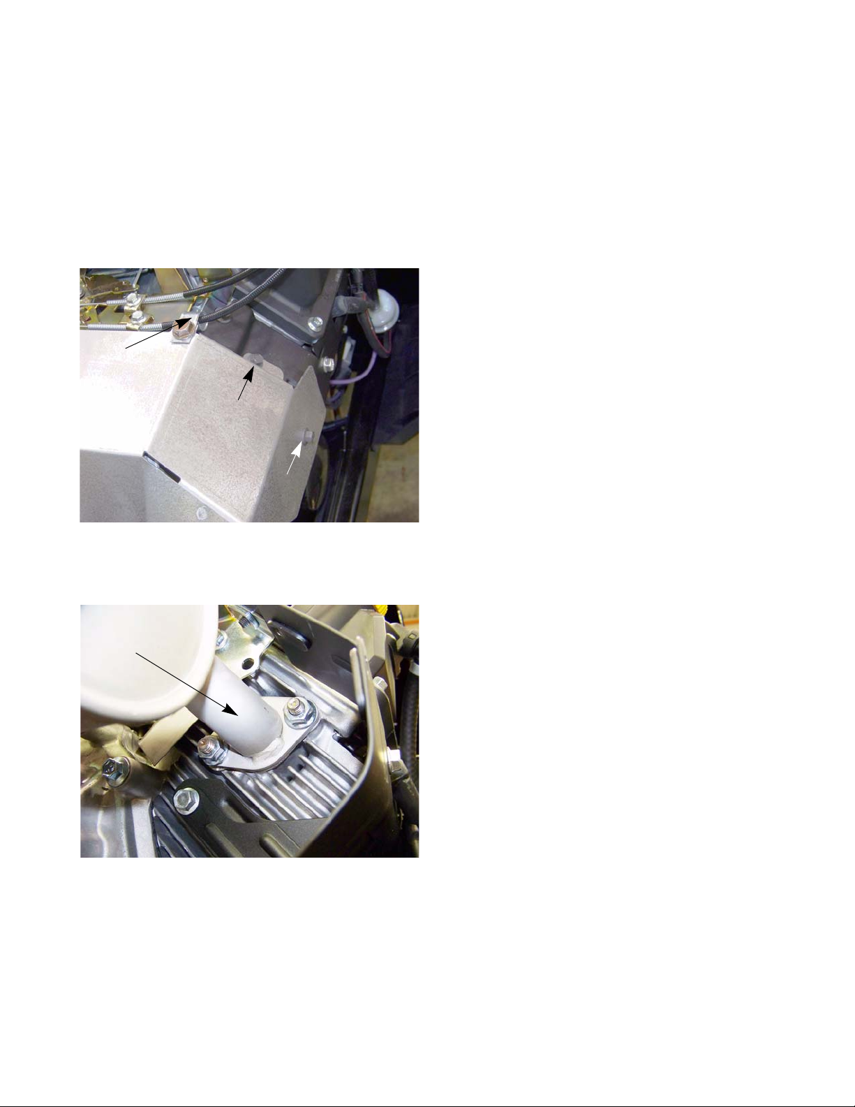
2. Remove the screw that holds the conduit clamp to
Conduit clamp
the heat shield using a 1/2” wrench. See Figure 2.1.
3. Remove the four screws (two on each side) that hold
the heat shield to the engine using a 5/16” wrench.
Exhaust pipe
Heat shield screws
4. Slide the heat shield off of the engine.
Figure 2.1
5. Remove the two nuts that hold each exhaust pipe to
the cylinder head using a 1/2” wrench.
See Figure 2.2.
6. Remove the muffler and exhaust pipes.
NOTE: The exhaust pipes are welded to the muffler. The
pipes and the muffler are serviced as one assembly.
7. Clean and remove all gasket material from the cylinder head (and the exhaust pipes if they are being
reused).
8. Using new gaskets, install the muffler by following the
previous steps in reverse order.
Figure 2.2
NOTE: Tighten the exhaust nuts to a torque of 246 in lbs
(27.8 Nm).
9. Test drive the mower in a safe area before returning
it to service.
5
Page 12
2000 Series Tractors
Fuel tank removal/replacement
Remove/replace the fuel tank by following these steps:
Gasoline and its vapors are extremely flammable. Use common sens e when working aroun d
! CAUTION! CAUTION
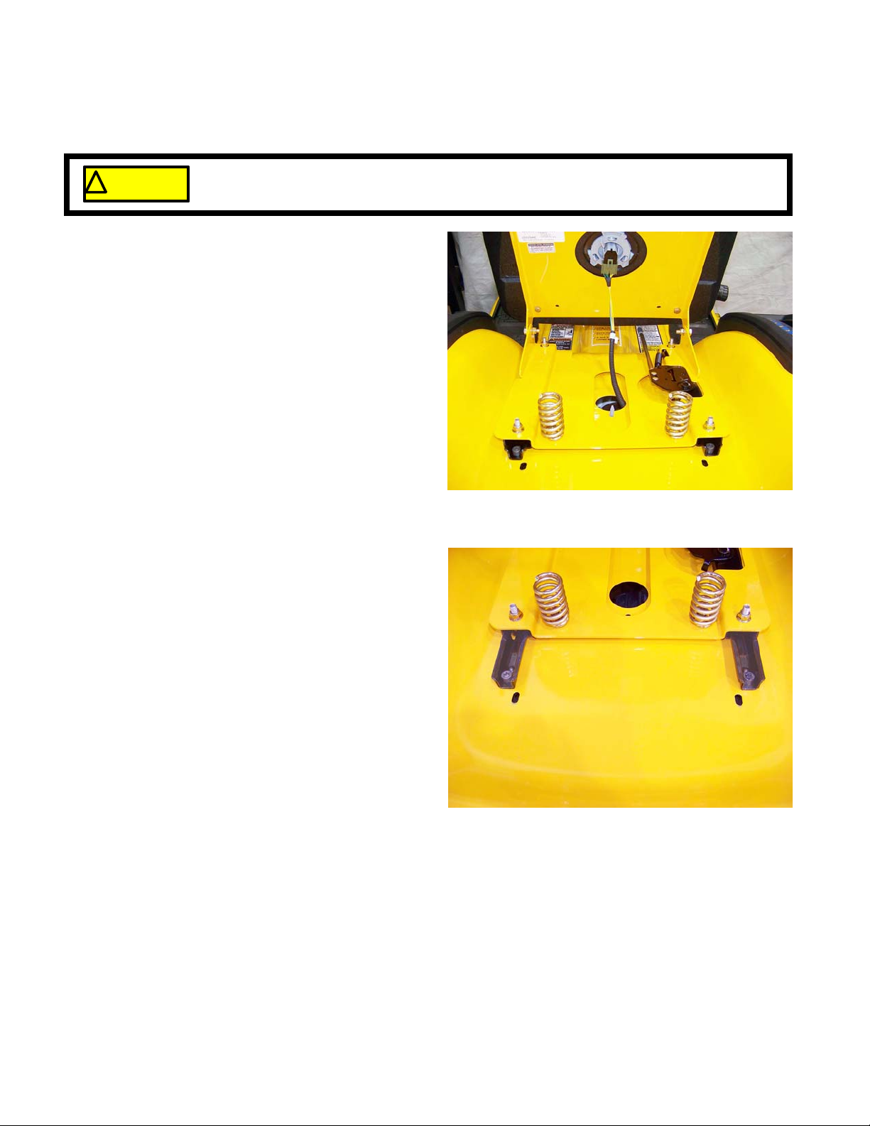
1. Safely drain the gasoline from the fuel tank.
2. Disconnect the seat switch. See Figure 2.3.
NOTE: On the GTX2154LE, it will be necessary to
cut the wire tie that holds the seat switch
connector to the seat frame.
NOTE: When reconnecting the seat switch plug on
the GTX2154LE, it must be wire tied back
together and attached to the seat frame.
Failure to do this can cause the connector to
get caught in the seat bracket and rip the
wires out of the seat. If this happens, the
tractor will shut down when the brake is
released and the whole seat must be
replaced.
3. Push the barbed fastener on the seat switch harness out of the hole in the fender.
the fuel system
Figure 2.3
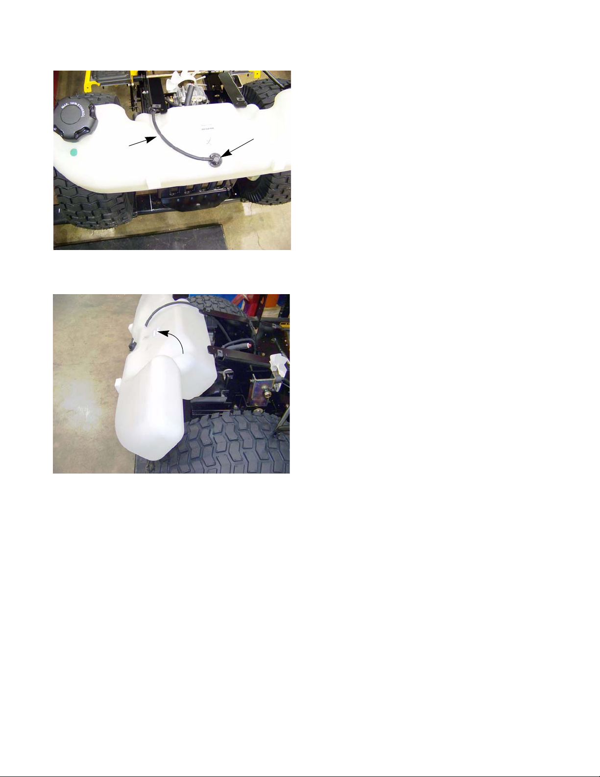
4. Remove the four socket headed cap screws that
hold the seat tracks to the fender using a T-40 torx
driver. See Figure 2.4.
Figure 2.4
6
Page 13
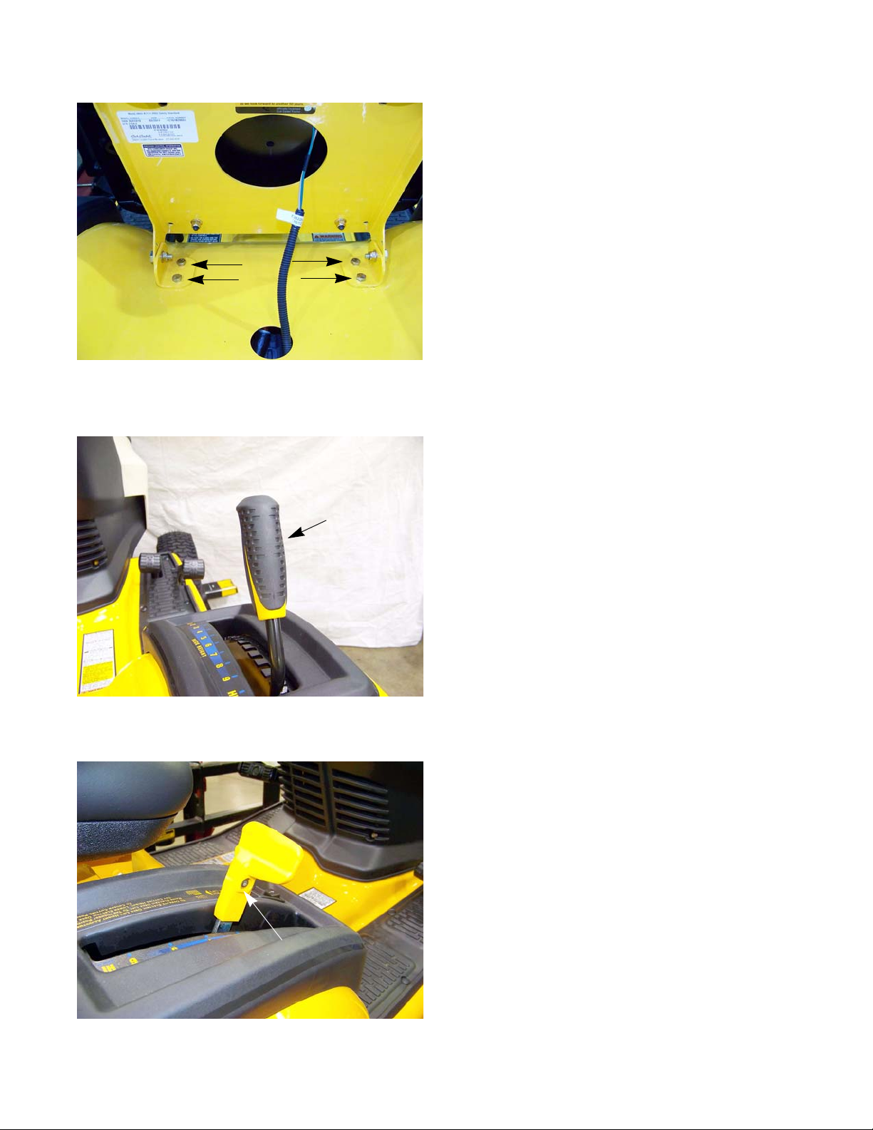
Figure 2.5
Engine Related Parts
NOTE: On the GTX2154LE:
• Remove the four screws, indicated by the arrows
in Figure 2.5, that hold the seat frame to the fender
using a 7/16” wrench.
• Remove the two screws that hold the rear of the
fender to the frame using a 7/16” wrench.
On manual deck lift models:
5. Remove the deck lift lever grip. See Figure 2.6.
NOTE: A blow-gun with air pressure regulate d to less than
Grip
Figure 2.6
On electric deck lift models:
6. Remove the screw that holds the deck cutting height
7. Pull the cutting height lever off of the shaft.
8. Disconnect the deck lift switch.
25 PSI (1.72 Bars), may be inserted into the small
hole at the end of a rubber grip to inflate it slightly,
easing removal.
lever to the shaft using a T40 torx driver.
Screw
Figure 2.7
7
Page 14
2000 Series Tractors
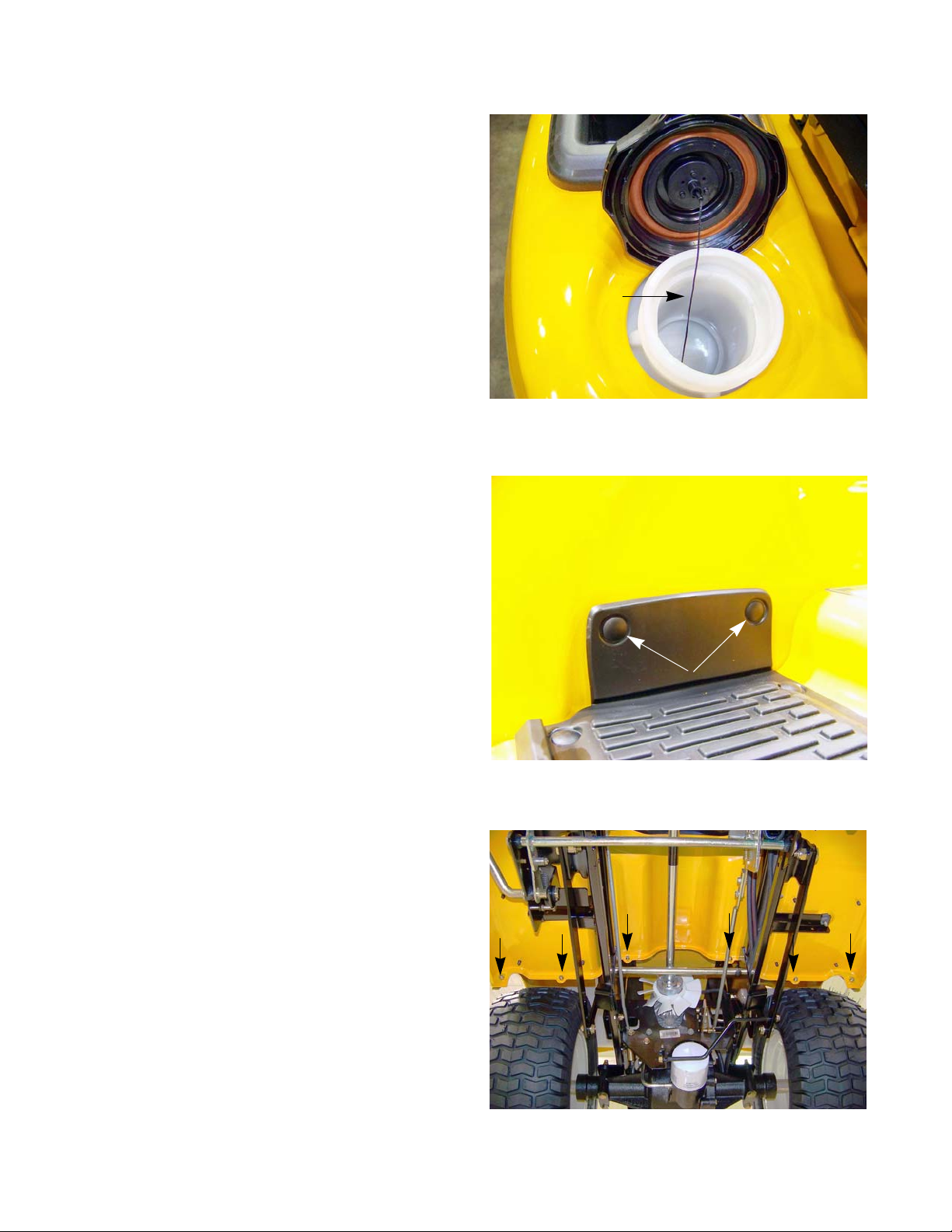
9. Unthread the fuel cap.
10. Pull the fuel cap tether retainer out of the fuel tank
using a long pair of pliers. See Figure 2.8.
NOTE: The fuel cap tether is manda ted by the EPA.
If it is broken, the fuel cap must be replaced.
Tether
Figure 2.8
11. Gently pry out the barbed fasteners that hold the
end of the running board mats to the fender.
See Figure 2.9.
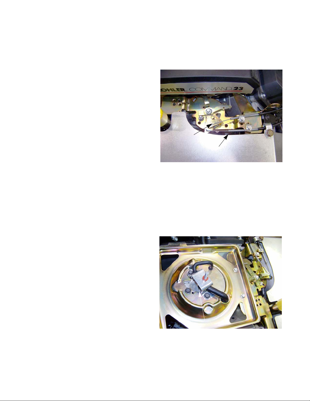
12. Remove the six nuts and bolts, indicated by the
arrows in Figure 2.10, that hold the fender to the
running board using a pair of 7/16” wrenches.
13. Lift the fender off of the tractor.
Barbed fasteners
Figure 2.9
Figure 2.10
8
Page 15
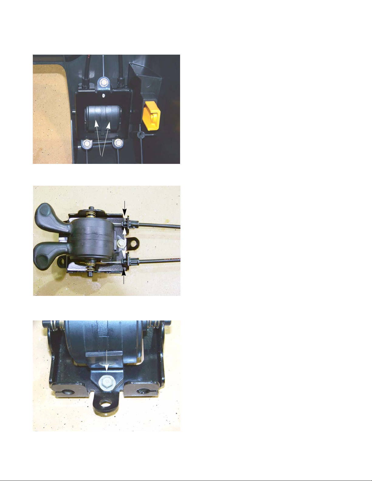
Vent hose
Engine Related Parts
14. Re-install the fuel cap.
15. Disconnect the vent hose from the roll over valve.
See Figure 2.11.
Roll over valve
Figure 2.11
Roll out
16. Roll the fuel tank towards the rear of the tractor until it
is free from the tractor. See Figure 2.12.
17. Disconnect the fuel line from the fuel tank.
18. Install the fuel tank by following the previous steps in
reverse order.
19. Test run the tractor in a safe area before returning it
to service.
Figure 2.12
9
Page 16
2000 Series Tractors
Throttle cable adjustment
If the engine does not achieve its high (no load) speed when the throttle is moved to the full throttle position,
check the cable adjustment before performing any other engine or carburetor inspections.
To adjust the throttle cable:
1. Raise the hood and locate the engine contro l panel.
2. Operate the throttle lever while observing its direction of movement. See Figure 2.13.
3. Loosen the screw that secures the throttle cable
clamp.
4. Push and hold the throttle arm at the full throttle
position.
5. While holding the throttle arm, remove the slack in
the cable by pulling the cable jacket back through
the clamp.
Choke cable
6. Tighten the screw in the clamp to secure the cable.
7. Start the engine.
8. Check the engine RPMs using a tachometer.
NOTE: Refer to the service manual provided by the
engine manufacturer for any further engine
speed adjustments needed.
Choke cable adjustment
If the engine is difficult to start or runs roughly after it warm s up, ch eck the choke c able setting befor e performing
any other engine or carburetor inspections.
To adjust the choke cable:
1. Remove the air filter.
2. Locate the engine control panel.
3. Loosen the screw that secures the choke cable
clamp.
4. Move the choke arm until the choke plate is fully
closed.
NOTE: Look down the carburetor throat to confirm
that the choke plate is fully closed.
See Figure 2.14.
Throttle cable
Figure 2.13
5. While holding the choke arm, remove the slac k in
the cable by pulling the cable jacket back through
the clamp.
6. Tighten the screw in the clamp to secure the cable.
7. Check the operation of the cable and choke plate.
8. Re-install the air filter.
9. Test run the tractor in a safe area before returnin g it to ser vic e.
10
Choke plate closed
Figure 2.14
Page 17
Choke and Throttle levers and cables
Control lever assemblies
Figure 2.15
Engine Related Parts
To remove/replace levers and cables:
NOTE: The choke and throttle cables must be removed
with the lever assemblies before they can be separated and replaced.
1. Remove the dash by following the procedures
described in Chapter 4: Body.
2. Remove the three screws that secure the control
lever assemblies in place using a 3/8” wrench.
See Figure 2.15.
3. Rotate the levers while pulling the assemblies out of
the dash.
4. Remove the cables:
Figure 2.16
Screw
4a. Squeeze in the ears on the cable jacket fittings.
See Figure 2.16.
4b. Slide the cable jackets out of the bracket.
4c. Un-hook the cables from the levers.
NOTE: If just replacing the cables, install the cables by fol-
low steps 1 - 4 in reverse order.
5. Remove the screw that holds the lever ret ainer to the
bracket using a 5/16” wrench. See Figure 2.17.
Figure 2.17
11
Page 18
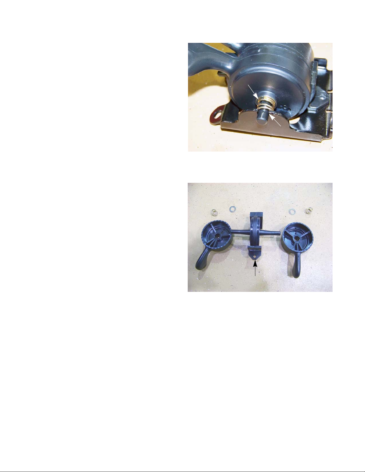
2000 Series Tractors
6. On the side of the lever assembly that has the slot,
lift the shaft that the levers pivot on enough to slide
the spring off. See Figure 2.18.
7. Slide the lever assembly toward the side with the
slot until the assembly clears the other side.
8. Slide the levers off of the indexing plate.
See Figure 2.19.
9. Install the levers and cables by following the previous steps in reverse order.
Spring
Slot
Figure 2.18
12
Indexing plate
Figure 2.19
Page 19
Engine removal/installation
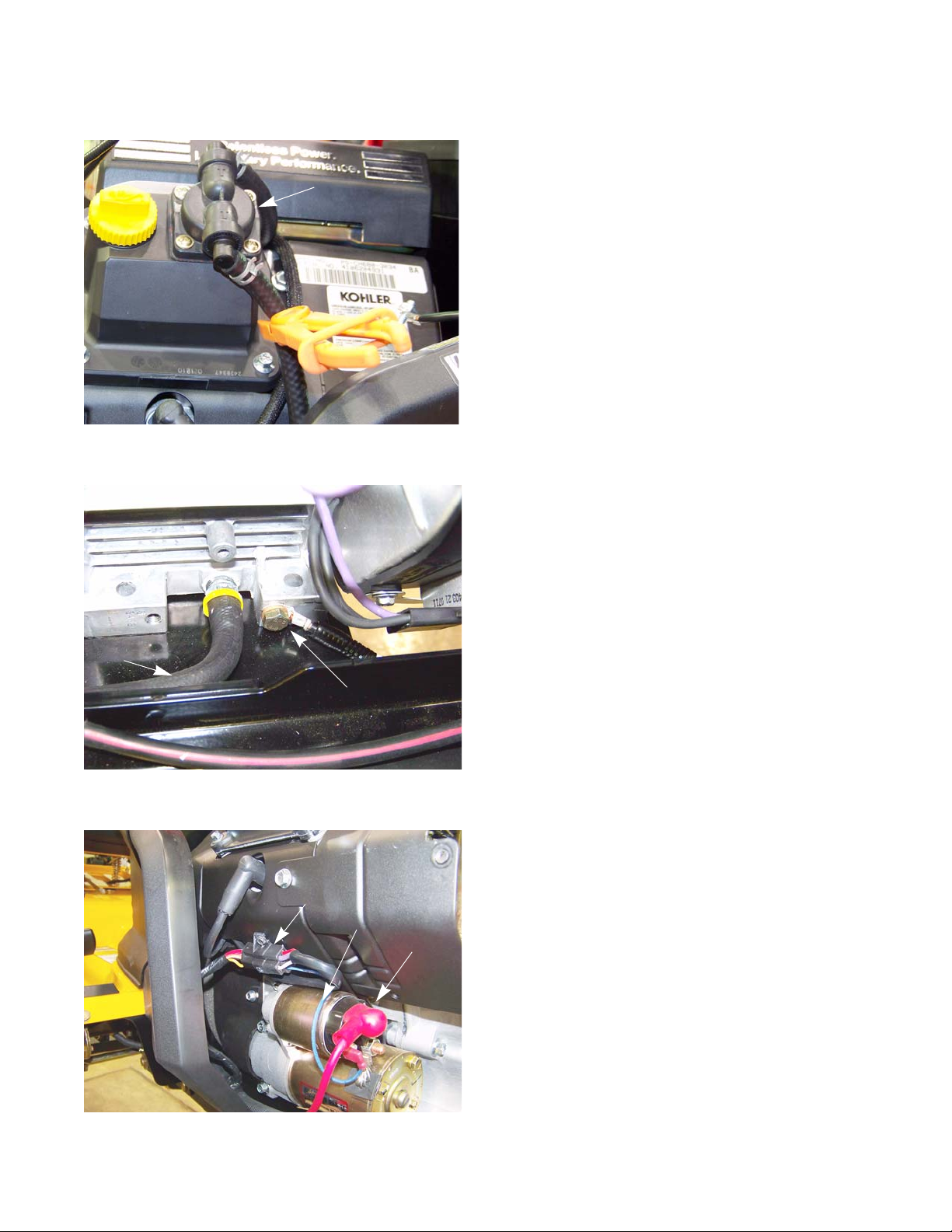
Figure 2.20
Fuel pump
Engine Related Parts
It may be necessary to remove the engine to perform
engine repairs such as replacing the ignition coil, flywheel,
alternator or to work on the cylinder heads.
To remove the engine:
1. Remove the hood by following the procedures
described in Chapter 4: Body.
2. Disconnect the negative battery cable from the battery.
3. Remove the muffler by following the proced ures
described in the muffler section of this chapter.
4. Clamp off the fuel line just below the fuel pump.
See Figure 2.20.
Oil drain hose
Ground cable
Figure 2.21
Engine harness
Starter trigger wire
Starter cable
5. Disconnect the ground cable from the left side of the
engine using a 1/2” wrench. See Figure 2.21 .
6. Disconnect the PTO clutch harness.
7. Disconnect the engine harness.
8. Disconnect the starter wires. See Figure 2.22.
9. Remove the starter.
Figure 2.22
13
Page 20
2000 Series Tractors
10. Remove the dash by following the procedures
described in Chapter 4: Body.
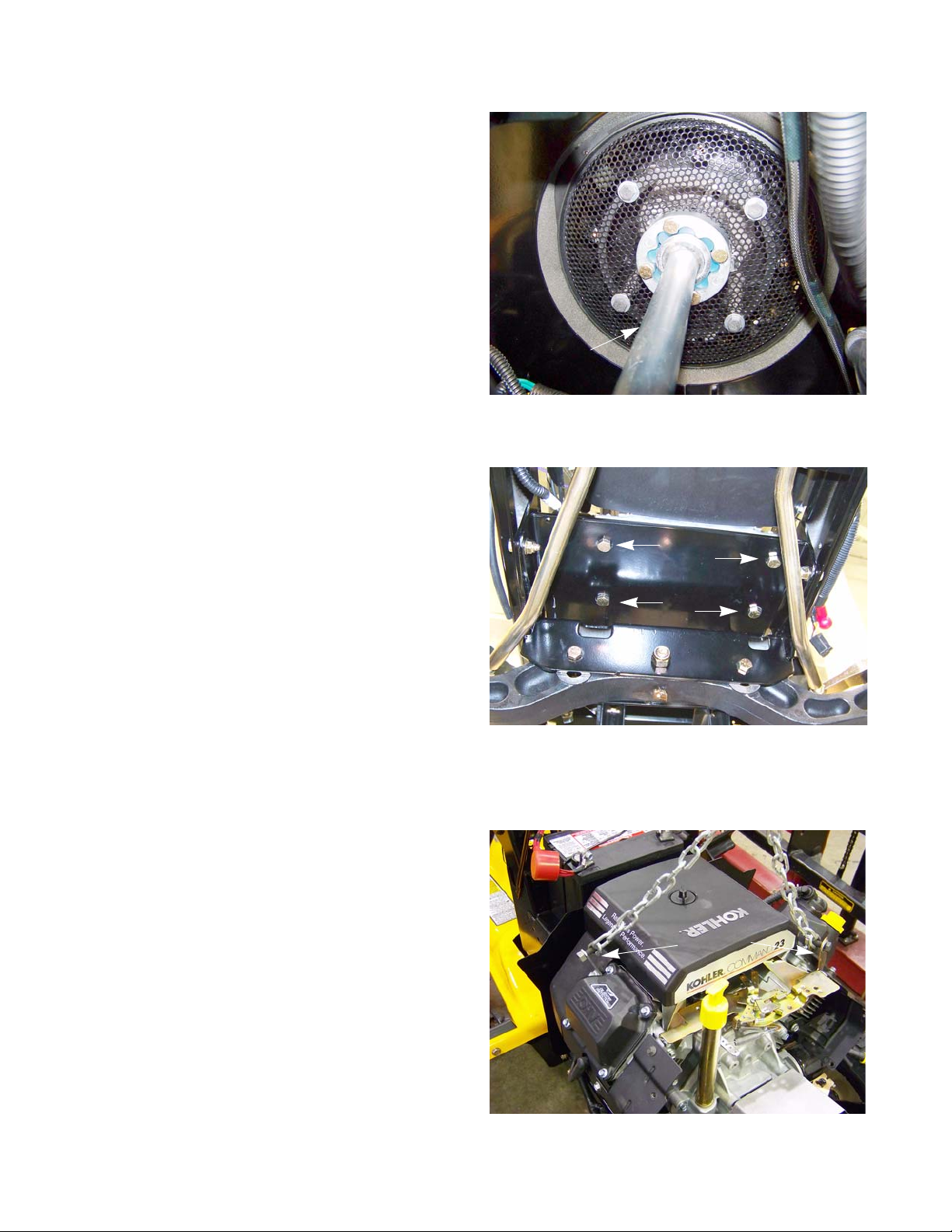
11. Disconnect the drive shaft from the engine by
removing the four patch bolts using a 7/16” wr en ch .
See Figure 2.23.
12. Remove the four nuts and bolts, indicated by the
arrows in Figure 2.24, that hold the engine to the
sub frame using a pair of 9/16” wrenches.
Drive shaft
Figure 2.23
13. Attach a lift chain to the engine’s lifting points.
See Figure 2.25.
NOTE: The lift chain should be approximately 2’ -
2.5’ (61 - 76 cm) long and is of sufficient
strength to safely support weight of the
engine.
14. Using an engine hoist, gently lift the engine while
sliding it off of the drive shaft and out the front of the
tractor.
NOTE: Be careful sliding the engine off of the drive
shaft. If the drive shaft coupling gets caugh t,
it will come apart, spilling the blue rollers on
the ground.
14
Figure 2.24
Lift points
Figure 2.25
Page 21
Blue rollers
Engine Related Parts
NOTE: If the front drive shaft coupling comes apart:
• Remove the engine.
• Insert the rollers in between the drive shaft end
and the coupler housing one at a time, until all
eight are in place. See Figure 2.26.
Figure 2.26
To install the engine:
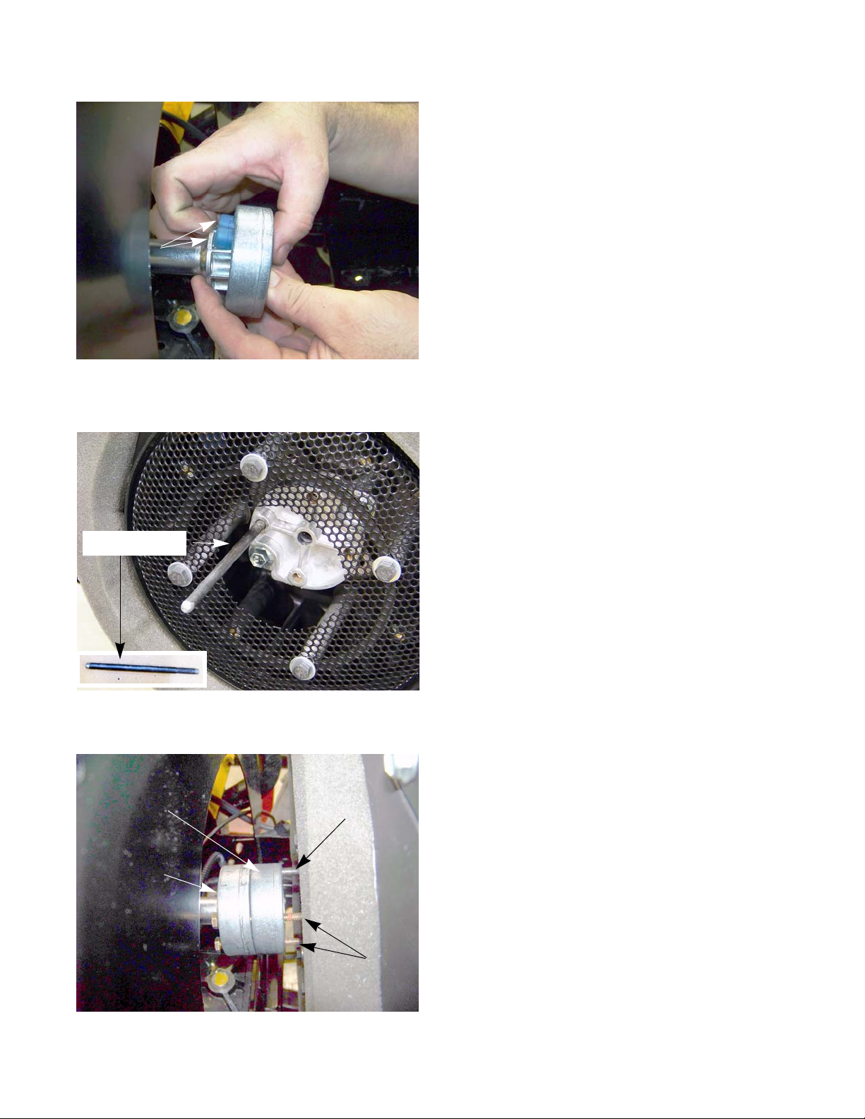
1. Install an alignment stud into one of the drive shaft
coupler holes on the engine. See Figure 2.27.
Alignment stud
Coupling spacer
Coupling
Figure 2.27
Alignment stud
NOTE: To make an alignment stud: See Figure 2.27.
• Obtain a 1/4” x 20 bolt that is a minimum of 4” long.
• Cut the head off of the bolt.
• Grind a tapper onto the side of the bolt the head
was on.
2. Insert three of the bolts into the coupling and the
spacer.
3. Slide the engine into place, using the alignment stud
to guide the drive shaft coupler into place.
See Figure 2.28.
4. Start the three coupling bolts.
5. Remove the alignment stud.
Figure 2.28
Coupling bolts
6. Install the fourth coupling bolt.
7. Tighten all of the coupling bolts to a torque of 10 - 12
ft lbs (14 - 16 Nm).
15
Page 22

2000 Series Tractors
8. Install the engine mounting nuts and bolts.
9. Remove the engine lift chain.
10. Install the dash by following the steps described in Chapter 4: Body.
11. Install the starter.
12. Reconnect the starter wires.
13. Reconnect the engine harness.
14. Reconnect the ground cable to the base of the engine.
15. Reconnect the fuel line to the fuel pump.
16. Install the muffler by following the procedures described in the muffler section of this chapter.
17. Install the hood.
18. Check the oil and fuel levels, top off as needed.
19. Test drive the tractor in a safe area before returning it to service.
16
Page 23
Brakes
CHAPTER 3: BRAKES
Brake adjustment
The transmission on the 2000 series tractor is driven by a Hydro-Gear BDU-10L pump. The pump will provide the
braking action when it is in operation. There is a mechani cal brake on the side of the tran smission. This brake is used
primarily as a parking brake. It is also used as a back up brake in cas e of a failure of the hydro pump.
The operation of the brakes should be tested before performing any adjustments.
To test the operation of the brakes:
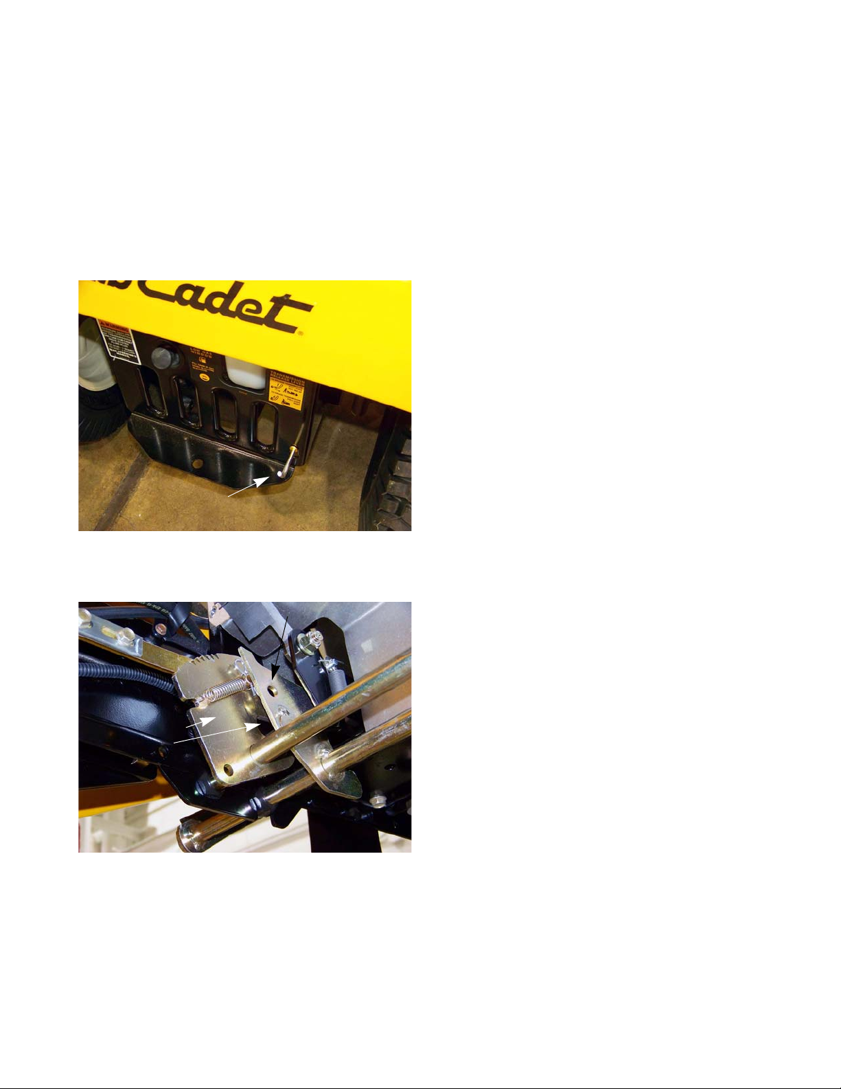
1. Disengage the hydro pump by-pass rod by pulling it
out and hooking it. See Figure 3.1.
2. Set the parking brake by depressing the brake pe da l
and lifting-up on the parking brake lever.
3. Attempt to push the tractor. If it can be pushed by
hand without skidding a rear wheel, check and adjust
the brakes.
4. Release the parking brake.
By-pass rod
Outer latch plate
travel limit pin
5. Attempt to push the tractor again. If it cannot be
pushed with reasonable effort, check the hydro pump
by-pass and adjust the brakes.
Figure 3.1
Inner latch plate
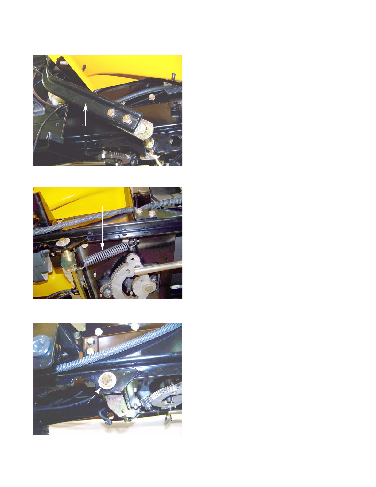
6. Visually inspect the linkage to confirm that it functions
properly.
• Beneath the floor panel, on the left side of the trac-
tor there are two semi-circular latch plates (bell
cranks).
• The outer latch plate rotates with the drive control
pedals. The inner latch plate rotates with the
clutch/brake pedal.
6a. With the clutch/brake pedal fully released:
• The travel limit pin should be resting against the
front of the curved slot. See Figure 3.2.
Figure 3.2
17
Page 24
2000 Series Tractors
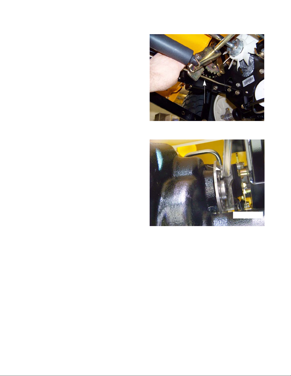
• The rod that connects the clutch/brake latch
plate to the heavy brake actuator spring should
not droop. See Figure 3.3.
• Check the brake pedal shaft bushings for wear.
Adjust the brakes by:
NOTE: The brake is located between the frame and
the transmission on the right side of the tractor. It is a tight fit, but it can be reached from
the under side of the tractor aft, of the rear
axle.
No droop
Figure 3.3
0.010” feeler gauge
NOTE: In Figure 3.4, the by-pass rod was removed
for a clearer view of the caliper.
1. Wiggle the brake rotor slightly, and attempt to insert
a 0.010” (0.38mm) feeler gauge between the rotor
and either pad.
NOTE: There is a fixed pad in the transaxle hous-
ing.
NOTE: There is a moving pad in the brake caliper.
2. Adjust the gap, if necessary, so that the feeler
gauge slips between the pad and the rotor with light pressure. See Figure 3.4.
2a. Turn the nut to adjust the gap.
NOTE: The gap should be in the range of 0.010” - 0.015” (0.25mm - 0.38mm)
2b. Apply and release the brake pedal, then re-check the gap.
NOTE: If the brake seems to be sticking, or the rotor is discolored from dragging, fix the cause of the sticking
and replace the rotor.
3. Re-test the operation of the brakes before returning the tractor to service.
Figure 3.4
Adjuster nut
18
Page 25
Brakes
Brake puck/rotor replacement
On transmission used on the 2000 series tractor , the brake pucks are wearing p a rts that will need to be serviced
from time to time. If the tractor is operated with the parking brake dragging, the pucks will wear out rapidly and the
brake rotor will develop hot spots. If the tractor is operated long enough, the rotor may have grinding marks on it with
excessively worn pucks.
! CA UTION! CA UTION
NOTE: The brake pucks and the rotors are serviced at the same time.
Screws
If the rotor shows hot spots or any other signs of damage, including warpage, it must be
replaced. Failure to do so can result in the failure of the brakes
To remove/replace the brake pucks and rotor:
1. Lift and safely support the rear of the tractor.
2. Remove the transmission by following the procedures describe in Chapter 5: Drive.
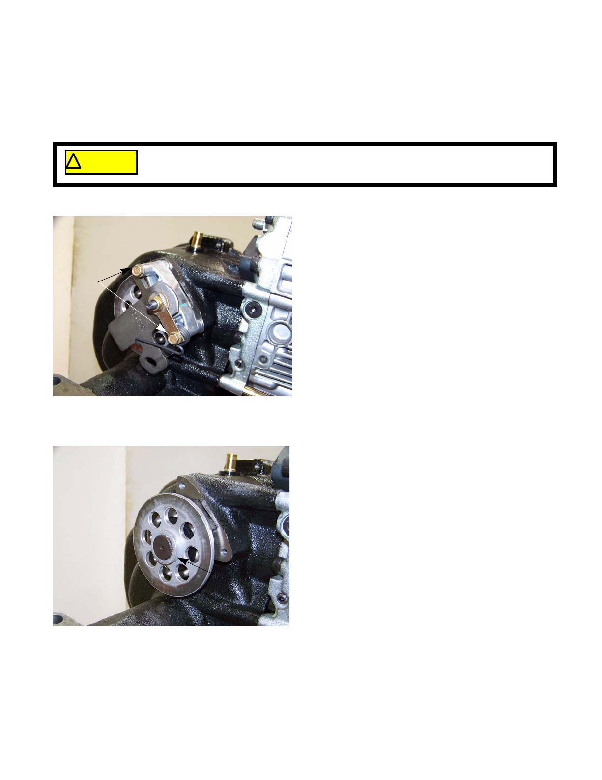
3. Remove the two screws that secure the brake caliper
to the right transmission housing using a 3/8” wrench.
See Figure 3.5.
4. Lift the caliper off of the transmission.
Figure 3.5
Figure 3.6
5. Remove the brake disk from the output shaft.
See Figure 3.6.
NOTE: The center flange of the brake disk faces outward.
Flange
19
Page 26
2000 Series Tractors
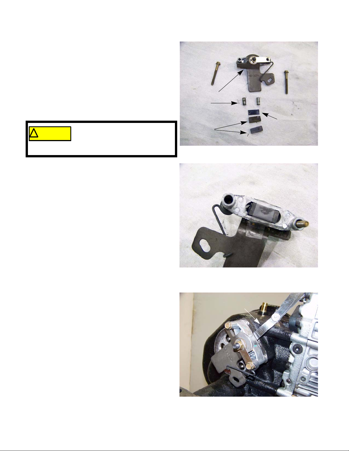
6. With the caliper on a work bench, remove the brake
puck, backing plate and the two brake pins.
See Figure 3.7.
7. Inspect all the components of the brake assembly
for damage or wear: brake pads, puck plate, actu ator pins, actuator arm, anti-rotation bracket, yoke,
torsion spring, flat washer and locking hex nut.
8. Check for free movement of the brake pins. A dry
lubricant can be used on the brake pins sparingly.
Never put grease or anti-seize on
! CA UTION! CA UTION
of the pucks.
9. Slide the brake pins into the caliper.
10. Place the backing plate in the caliper.
11. Place a new puck into the caliper. See Figure 3.8.
NOTE: A piece of scotch tape may be used to hold
brake pins. It can migrate to the brake
pucks, preventing the braking action
the new brake pucks in place for assembly.
The tape will grind away when the brakes
are applied.
Caliper
Pins
Backing plate
Pucks
Figure 3.7
12. Place a new brake puck into the recess in the transmission. Use a piece of scotch tape to hold it in
place.
13. Slide the brake rotor in place, shoulder out.
14. Mount the brake caliper to the transmission. Apply a
small amount of releasable thread locking compound such as Loctite® 242 (blue) to the mounting
bolts and tighten to a torque of 80 - 120 in-lbs (9 -
13.5 Nm).
15. Wiggle the brake rotor slightly and insert a 0.010”
(0.38mm) feeler gauge between the rotor and either
pad.
16. Adjust the gap, if necessary, so that the feeler
gauge slips between the pa d and the rotor with light
pressure. See Figure 3.9.
16a. Turn the nut to adjust the gap.
NOTE: The gap should be in the range of 0.010” -
0.015” (0.25mm - 0.38mm)
16b. Operate the brake cam arm a few times, then
re-check the gap.
17. Install the transmission by following the procedures
described in Chapter 5: Drive System.
Figure 3.8
0.010” feeler gauge
18. Test drive the tractor in a safe area before returning
it to service.
20
Figure 3.9
Page 27
Brake shaft assembly
Brake pedal
Brakes
To remove/replace the brake shaft:
1. Remove the cutting deck by following the procedures
described in Chapter 8: Cutting Decks and Lift shaft.
2. Lift and safely support the tractor.
3. Remove the forward drive pedal shaft by following
the procedures described in Chapter 5: Drive System.
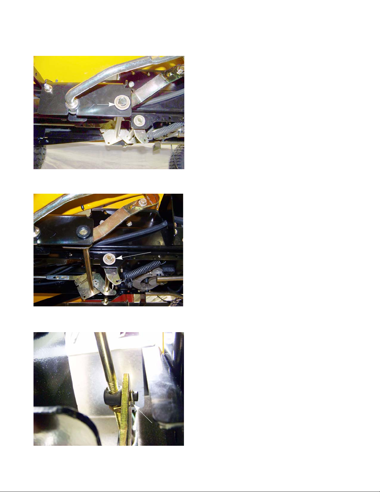
4. Disconnect the brake pedal by removing the two nuts
and bolts that attach it to the brake pedal shaft using
a pair of 1/2” wrenches. See Figure 3.10.
Figure 3.10
Brake shaft return spring
Figure 3.11
5. Disconnect the brake shaft return spring.
See Figure 3.11.
6. Remove the E-ring and washer(s) fr om the right side
of the brake shaft. See Figure 3.12.
7. Remove the hex bushings from both ends of the
brake pedal shaft.
E-ring
Figure 3.12
21
Page 28

2000 Series Tractors
8. Slide the brake pedal shaft to the left enough for it to
clear the frame on the right side.
9. Lower the shaft enough to gain access to the cotter
pin that secures the brake rod to the pedal shaft.
10. Remove and discard the cotter pin.
See Figure 3.13.
11. Remove the pedal shaft from the tractor.
12. Install the brake pedal shaft by following the previous steps in reverse order.
NOTE: The cotter pin that secures the br ak e ro d to
the pedal shaft can be replaced with a bow
tie clip (714-04040). This will make it easier
to perform the brake rod adjustment.
13. Perform a brake rod adjustment by following the
procedures described in the brake rod ad jus tm en t section of this chapter.
14. Test drive the tractor in a safe area before returning it to service.
Cotter pin
Figure 3.13
22
Page 29
Brake rod adjustment
E-ring
Brakes
NOTE: The brake rod should not come out of adjustment
on its own. If the brake rod does need to be
adjusted, check for a bent rod, worn bushing and
worn brake pucks.
To adjust the brake rod:
1. Remove the cutting deck by following the procedures
described in Chapter 8: Cutting Decks and Lift Systems.
2. Lift and safely support the tractor.
3. Remove the E-ring and washers from the right side of
the forward drive pedal shaft. See Figure 3.14.
Figure 3.14
Figure 3.15
4. Slide the drive pedal shaft to the left until it stops.
5. Remove the E-ring and washer(s) fr om the right side
of the brake pedal shaft. See Figure 3.15.
6. Slide the brake pedal shaft to the left until it stops.
E-ring
7. Disconnect the brake rod from the brake pedal shaft
by removing the cotter pin and discarding it.
See Figure 3.16.
Figure 3.16
Cotter pin
23
Page 30

2000 Series Tractors
8. Loosen the jam nut. See Figure 3.17.
9. Tighten or loosen the ferrule as needed so that it
aligns with the hole in the bell crank of the brake
pedal shaft with no slack in the brake spring.
10. Tighten the jam nut.
11. Attach the brake rod to the brake pedal shaft.
NOTE: The cotter pin that secures the br ak e ro d to
the pedal shaft can be replaced with a bow
tie clip (714-04040).
12. Slide the brake pedal shaft to the right until it stops.
13. Install the E-ring and washer(s) on to the brake
pedal shaft.
NOTE: If the bushings popped out while shifting the
shafts, re-install them before installing the E-rings.
14. Slide the forward drive pedal shaft to the right until it stops.
15. Install the E-ring and washer(s) on to the drive pedal shaft.
16. Test drive the tractor in a safe area before returning it to service.
Ferrule
Jam nut
Figure 3.17
24
Page 31
Body
CHAPTER 4: BODY
What is covered by this chapter
The intent of this chapter is to describe the removal and disassembly of the major body panels on the tractor.
•Hood
•Seat
• Fenders
• Dash panel
NOTE: It is not absolutely necessary to remove the mowing deck for any procedures covered in this section.
The technician may choose to remove the mowing deck so that it is easier to reach some parts of the
tractor.
Hood
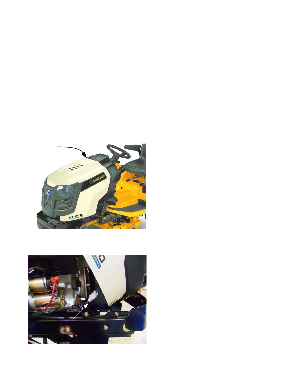
Lift here
Hood removal:
1. The hood is front-hinged. See Figure 4.1.
2. Open the hood by lifting the rear edge to tilt it forward.
Figure 4.1
3. Disconnect the headlight harness. See Figure 4.2.
Headlight harness connector
Figure 4.2
25
Page 32
2000 Series Tractors
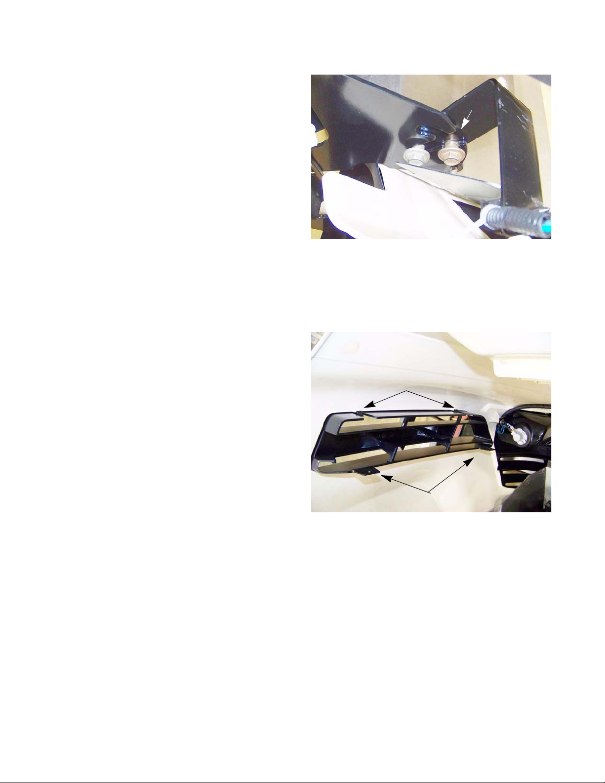
4. The hood hinges on a pair of shoulder bolts that fit
into slots in the hood bracket.
5. The hinge travel is limited by a tab that fits into a
channel in the hood bracket.
6. Open the hood far enough to align the tabs with the
slots, then lift the hood off of the tractor.
See Figure 4.3.
Hood components: side vent removal
Slot
Figure 4.3
1. Carefully pry the vent free of the lock tabs.
2. Pull the vent out of the hood assembly.
3. Install the hood side vent by pressing it into the
hood-side opening until the lock tabs click into
place, securing the vent.
2 lock tabs on top
2 lock tabs on bottom
Figure 4.4
26
Page 33

Hood components: Headlight removal
Figure 4.5
Body
1. With the spade terminals disconnected, rotate the
lamp holder (socket) to release it from the grille
assembly. See Figure 4.5.
LED headlight assembly
Figure 4.6
Single-pin 1156-style lamp
Socket
NOTE: The GTX2154LE has a LED headlight assembly. It
is removed the same way as the incandescent
headlight assemblies.
2. Rotate the bulb to release it from the socket.
See Figure 4.7.
NOTE: The LED assembly does not come apart.
3. Install the replacement lamp following the above
steps in reverse order.
Ground terminal
Power terminal
Figure 4.7
27
Page 34

2000 Series Tractors
Hood components: grille removal
1. Remove the hood assembly from the tractor, and
place it on a stable work surface.
2. Disconnect the wires from the headlights.
3. Remove the two screws, one in each head lig h t
housing, that hold the upper corners of the grille to
the hood using a 5/16” wrench. See Figure 4.8.
4. Remove the four screws, indicated by the arrows in
Figure 4.9, using a 3/8” wrench.
Screw +
washer
Figure 4.8
5. Slide the heat shield out of the hood.
Figure 4.9
28
Page 35

Screws
Figure 4.10
Body
6. Remove the two screws that hold the pivot bracket
and grille to the hood assembly using a 3/8” wrench.
See Figure 4.10.
7. Unlatch the tabs, where the screws were in step 3,
while pushing the grille out of the hood.
Locating tab
Figure 4.11
Lock tabs
8. Once removed, the headlight lens may be removed
for cleaning by carefully prying the two lock tabs at
the inner edge. See Figure 4.11.
NOTE: The locating tab at the outer edge of each len s has
no locking feature.
9. Assemble and install the grille by reversing the steps
used to remove it.
• Tighten the small screws to a torque of 15-35 in-
lbs. (1.7-4.0 N-m).
• Tighten the large screws to a torque of 35-50 in-lbs
(4.0-5.7 N-m).
29
Page 36

2000 Series Tractors
Hood components: pivot bracket removal
1. Remove the hood assembly from the tractor, and
place it on a stable work surface.
2. Remove the four screws, indicated by the arrows in
Figure 4.12, using a 3/8” wrench.
3. Slide the heat shield out of the hood.
Figure 4.12
4. Remove the two screws that hold the pivot bracket
and grille to the hood assembly using a 1/2” wrench.
See Figure 4.13.
5. Remove the four screws, indicated by the arrows in
Figure 4.14, that hold the outer arms of the pivot
bracket to the hood using a 3/8” wrench.
6. Assemble and install the grille by reversing the
steps used to remove it.
Screws
Figure 4.13
• Tighten the small screws to a torque of 15-35
in-lbs. (1.7-4.0 N-m).
• Tighten the large screws to a torque of 25-45
in-lbs (2.80-5.1 N-m).
30
Figure 4.14
Page 37

Fender and running board
On the Cub Cadet 2000 series tractor, the fender and the running board are two pieces. It may be necessary to
remove the fender and running board to gain access to items such as the deck lift shaft
When removing the fender and running board, it is generally easier to remove both of them as one piece.
NOTE: When working on the fuel tank, only the fender needs to be removed.
To remove/replace the fender:
1. Disconnect the seat switch. See Figure 4.15.
NOTE: On the G TX2154LE, it will be necessary to cut the
wire tie that holds the seat switch connector to the
seat frame.
NOTE: When reconnecting the seat switch plug on the
GTX2154LE, it must be wire tied back together
and attached to the seat frame. Failure to do this
can cause the connector to get caught in the seat
bracket and rip the wires out of the seat. If this
happens, the tractor will shut down when the brake
Barbed fastener
2. Push the barbed fastener on the seat switch harness
Figure 4.15
is released and the whole seat must be replaced.
out of the hole in the fender.
Body
Screws
Figure 4.16
3. Remove the four socket headed cap screws that hold
the seat tracks to the fender using a T-40 torx driver.
See Figure 4.16.
31
Page 38

2000 Series Tractors
NOTE: On the GTX2154LE:
• Remove the four screws, indicated by the
arrows in Figure 4.17, that hold the seat frame
to the fender using a 7/16” wrench.
• Remove the two screws that hold the rea r of the
fender to the frame using a 7/16” wrench.
On manual deck lift models:
4. Remove the deck lift lever grip. See Figure 4.18.
NOTE: A blow-gun with air pressure regulated to
less than 25 PSI (1.72 Bars), may be
inserted into the small hole at the end of a
rubber grip to inflate it slightly, easing
removal.
Figure 4.17
Grip
On electric deck lift models:
4. Remove the screw that holds the deck cutting
height lever to the shaft using a T40 torx driver.
5. Pull the cutting height lever off of the shaft.
6. Disconnect the deck lift switch.
32
Figure 4.18
Screw
Figure 4.19
Page 39

Tether
Body
7. Unthread the fuel cap.
8. Pull the fuel cap tether retainer out of the fuel tank
using a long pair of pliers. See Figure 4.20.
NOTE: The fuel cap tether is mandated by the EPA. If it is
broken, the fuel cap must be replaced.
Figure 4.20
9. Remove the reverse drive pedal using a 9/16”
wrench. See Figure 4.21.
Reverse pedal
Figure 4.21
Screw
10. Remove the forward drive pedal using a 9/16”
wrench.
Forward
pedal
11. Remove the two screws, one on each side, that hold
the front of the running board to the running board
brackets using a 1/2” wrench.
Figure 4.22
33
Page 40

2000 Series Tractors
12. Gently pry up the rubber foot pad on one side of the
tractor enough to gain access to the screw under it.
See Figure 4.23.
13. Remove the screw using a 1/2” wrench.
14. Repeat steps 10 & 11 on the other side of the tractor.
15. Remove running board brackets by removing the
two screws, indicated by the arrows in Figure 4.24,
that hold each of them to the frame using a 1/2”
wrench.
Rubber foot pad
Screw
Figure 4.23
16. Lift the rear of the fender far enough for it to clear
the fuel tank and slide the fender off of the tractor.
NOTE: If the running board and fender need to be
separated:
• Remove the six nuts and bolt s, indicated by the
arrows in Figure 4.25, that hold the fender to
the running board using a pair of 7/16”
wrenches.
17. Install the fender and running board b y following the
previous steps in reverse order.
NOTE: The seat switch connector on the
G TX2154LE must be wire tied back together
and attached to the seat frame. Failure to do
this can cause the connector to get caught in
the seat bracket and rip the wires out of the
seat. If this happens, the tractor will shut
down when the brake is released and the
whole seat must be replaced.
Figure 4.24
Figure 4.25
34
Page 41

Dash Panel
Body
The dash panel may be removed to provide access to the
tilt steering column, power steering, or to replace the da sh
or dash support brackets.
Cover
1. Remove the steering wheel
1a. Remove the cover from the center of the steer-
ing wheel. See Figure 4.26.
1b. Remove the bolt that holds the steering wheel
to the steering shaft using a 1/2” wrench.
1c. Lift the steering wheel off of the shaft.
2. Disconnect the negative battery cable.
Figure 4.26
Figure 4.27
Choke cable
3. Remove the bowtie clip that holds the control rod to
the cruise/parking brake lever. See Figure 4.27.
4. Slide the control rod out of the cruise/parking brake
lever.
.
Bow tie clip
5. Disconnect the throttle cable from the control panel
on the engine. See Figure 4.28.
NOTE: Mark the cable and the hole it goes into to ensure it
goes back into the proper hole on re-assembly.
6. Disconnect the choke cable from the control panel on
the engine.
Throttle cable
Figure 4.28
NOTE: Mark the cable and the hole it goes into to ensure it
goes back into the proper hole on re-assembly.
35
Page 42

2000 Series Tractors
7. Disconnect the PTO switch. See Figure 4.29.
8. Disconnect the hour meter.
9. Remove the two screws, indicated by the ar ro ws in
Figure 4.30, that hold the left side of the dash to the
dash support bracket using a 3/8” wrench.
Hour meter
PTO switch
Figure 4.29
10. Remove the two screws that hold the right side of
the dash to the dash support bracket using a 3/8”
wrench. See Figure 4.31.
36
Figure 4.30
Screws
Figure 4.31
Page 43

Figure 4.32
Body
11. Remove the two screws, indicated by the arrows in
Figure 4.32, from the bottom of the operators side of
the dash using a 3/8” wrench.
12. Remove the two screws, indicated by the arrows in
Figure 4.33, that holds the base of the left side panel
to the frame using a 1/2” wrench
13. Lift up on the dash enough to disconnect the RMC
module and the key switch.
14. Lift the dash panel off of the tractor.
15. Assembly notes:
• Assemble tractor by reversing the disassembly
process.
• Tighten fasteners to a torque of 20-22 in-l bs. (2.25-
2.50 N-m).
Figure 4.33
NOTE: The seat switch connector on the GTX2154LE must be wire tied back together and attached to the
seat frame. Failure to do this can cause the connec to r to ge t cau g ht in th e sea t br acket and rip the
wires out of the seat. If this happens, the tractor will shut down when the brake is released and the
whole seat must be replaced.
• Test all tractor controls and features before return-
ing the tractor to service.
37
Page 44

2000 Series Tractors
38
Page 45

Transmission fluid filter
Anti-sway rod
Drive
CHAPTER 5: DRIVE SYSTEM
The oil filter should be changed every 100 hours.
NOTE: The filter can be changed without draining all of the
transmission fluid.
To change the transmission fluid filter:
1. Remove the deck as described in chapter 8: Cutting
Decks and Lift Systems.
2. Lift and safely support the rear of the tractor.
3. Remove the nut that secures the anti-sway rod to the
transmission torque bracket. See Figure 5.3.
4. Slide the anti-sway rod out of the torque bracket.
Oil filter
Figure 5.1
Figure 5.2
5. Clean around the oil filter to prevent any dirt from getting into the transmission.
6. Place a suitable container under the transmission filter to catch any fluid that may be spilled while changing the filter.
7. Pre-fill a new filter with Cub Cadet Drive System Fluid
Plus oil (#737-3120).
8. Apply a light coating of oil to the O-ring of the new filter.
NOTE: To minimize the amount of oil lost, have the new fil-
ter ready to be installed as the old filter is removed.
9. Remove and discard the oil filter using a suitable
strap wrench. See Figure 5.2.
10. Quickly install the oil filter hand tight.
1 1. Check the transmission oil level by using the dip stick
at the rear of the tractor. Top off as needed.
12. Test drive the tractor in a safe area before returning it
to service.
39
Page 46

2000 Series Tractors
Transmission fluid change
NOTE: The transmission is filled with a high quality,
specially blended oil. It only needs to be
changed if it is contaminated.
To change the transmission fluid:
1. Remove the deck as described in chapter 8: Cutting
Decks and Lift Systems.
2. Lift and safely support the rear of the tractor.
3. Clean the transmission around the drain plug area.
4. Remove the drain plug using a 16 mm wrench.
See Figure 5.1.
5. Remove the dip stick.
6. Remove the oil filter by following the procedures
described in the transmission oil filter section of this
chapter.
7. Install the oil drain plug.
8. Pre-fill a new filter with Cub Cadet Drive System Fluid Plus (#737-3120).
9. Apply a light coating of Cub Cadet Drive System Fluid Plus to the O-ring of the new filter.
10. Install a new oil filter hand tight.
11. Fill the transmission with 182 oz (5.4 L) of Cub Cadet Drive System Fluid Plus (#737-3120)
NOTE: The Cub Cadet Drive System Fluid Plus (#737-312 0) is a synthetic blended oil d esigned specifically for
Cub Cadet transmissions.
12. Purge the transmission while the tractor is still supported off of the ground.:
Drain plug
Figure 5.3
12a. Move the by-pass rod to the by-pass position.
12b. Start the engine.
12c. Cycle the drive pedal from full forward to full reverse six times.
12d. Move the by-pass rod to the drive position.
12e. Cycle the drive pedal from full forward to full reverse six times.
13. Test drive the tractor before returning it to service.
40
Page 47

Drive shaft
Drive
Hydro pump
Figure 5.4
To remove/replace the drive shaft:
1. Remove the deck as described in chapter 8: Cutting
Decks and Lift Systems.
2. Remove the dash by following the procedures
described in Chapter 4: Body.
3. Remove the fender and running board by following
the procedures described in Chapter 4: Body.
4. Remove the four screws that attach the drive shaft to
the hydro pump using a 7/16” wrench.
See Figure 5.4.
Drive shaft
5. Remove the four screws that attach the drive shaft to
the engine using a 7/16” wrench. See Figure 5.5.
6. Lift the drive shaft out of the tractor.
NOTE: There is a spacer between the drive shaft and the
engine.
Drive shaft
Figure 5.5
7. Install the drive shaft by following the previous steps
in reverse order.
NOTE: Apply a small amount of a releasable thread lock-
ing compound such as Loctite® 242 (blue) to the
drive shaft screws.
NOTE: Tighten the drive shaft screws to a torque of 10 -
12 ft lbs (14 - 16 Nm).
8. Test drive the tractor in a safe area before re turning it
to service.
41
Page 48

2000 Series Tractors
Hydro neutral control adjustment
NOTE: Neutral control rarely goes out of adjustment on its own. If it needs adjustment, check for damaged
linkage or signs of tampering.
The tractor’s engine and drive system must be operated to complete this pr ocedure. Confirm
! CA UTION! CA UTION
To perform the hydro neutral control adjustment:
1. Lift and safely support the rear of the tractor.
2. By-pass the seat safety switch. See Figure 5.6.
2a. Slide the seat to the full forward position.
2b. Flip the seat up.
2c. Press in the seat bottom until the tang on the
seat switch is fully extended.
that no hazards will be incurred by running the engine or operating the drive system.
• Work in a well vented area to prevent carb on monoxide poiso ning or asphyxiation.
• Be careful to avoid contact with hot parts or moving parts.
Seat switch
2d. Place a spring clamp on the tang to hold the
seat switch in this position.
3. Disconnect the drive control rod from the hydro
pump by removing the bow tie clip. See Figure 5.7.
Figure 5.6
Bow tie clip
Figure 5.7
42
Page 49

Figure 5.8
Drive
4. Start the engine and advance throttle to maximum
RPM.
5. Release the parking brake.
6. Watch both rear tires for movement.
See Figure 5.8.
NOTE: If there is no wheel movement, the hydro pump is
in neutral and doesn’t need to be adjusted. Skip to
step 14.
NOTE: If one or both rear wheels move, the hydro pump
needs to be adjusted.
To adjust the hydro pump:
7. Turn off the engine.
Drive control rod
Figure 5.9
8. Loosen the two screws, indicated by the arrows in
Figure 5.9, that hold the return to neutral bracket to
the transmission torque bracket using a 1/2” wrench.
9. Start the engine and advance the throttle to maximum RPMs.
10. Move the return to neutral bracket forward or backwards until the wheel(s) stops moving.
11. Tighten the two screws using a 1/2” wrench.
12. Confirm that the adjustment did not shift when the
screws were tightened.
13. Turn-off the engine.
14. Set the parking brake.
15. Loosen the two screws at the front of the drive control
rods using a 3/8” wrench. See Figure 5.10.
16. Adjust the length of the drive control rod so that it
slides freely onto the pin on the hydro selector plate.
Install the bow tie clip.
Figure 5.10
17. Tighten the two screws at the front of the drive control rod using a 3/8” wrench.
18. Lower the tractor to the ground.
19. Test the drive system and all safety features before
returning the unit to service.
43
Page 50

2000 Series Tractors
Trans mission removal/replacement
To remove/replace the transmission:
1. Remove the deck as described in Chapter 8 Cutting
Decks and Lift Shaft.
NOTE: If the transmission is being removed to o pen
it up, drain the fluid at this point by following
the procedures described in th e tra nsmission fluid change section of this chapter.
2. Lift and safely support the rear of the tractor.
3. Remove the nut that secures the anti-sway rod to
the transmission torque bracket. See Figure 5.11.
4. Slide the anti-sway rod out of the torque bracket.
Anti-sway bar
Figure 5.11
5. Remove the brake rod:
5a. Remove the E-ring, bushing and washers
from the right side of the forward drive pedal
shaft. See Figure 5.12.
5b. Slide the drive pedal shaft to the left until it
clears the frame.
NOTE: Let the drive pedal shaft hang there.
5c. Remove the E-ring and washer(s) from the
right side of the brake pedal shaft.
See Figure 5.13.
5d. Slide the brake pedal shaft to the left until it
stops.
E-ring
Drive pedal shaft
Brake pedal shaft
Figure 5.12
E-ring
44
Figure 5.13
Page 51

Figure 5.14
Drive
5e. Disconnect the brake rod from the brake pedal
shaft by removing and discarding the cotter pin.
See Figure 5.14.
Cotter pin
Bow tie clip
Brake pedal shaft
Drive pedal shaft
Control rod
Figure 5.15
Bow tie clip
Brake rod
5f. Pull back on the brake rod and maneuver it past
the brake shaft and forward drive shafts.
5g. Unhook the brake rod from the brake spring.
6. Remove the drive control rod:
6a. Remove the bow tie clip that holds the drive
control rod and spring to the bell crank on the
pedal shaft. See Figure 5.15.
6b. Remove the bow tie clip that holds the drive
control rod to the hydro pump. See Figure 5.16.
6c. Slide the control rod off of the pin.
Figure 5.16
45
Page 52

2000 Series Tractors
7. Remove the by-pass rod:
7a. Remove the bow tie clip. See Figure 5.17.
7b. Slide the by-pass rod out the rear of the trac-
tor.
8. Remove the rear wheels by removing the four lug
nuts that secure each wheel to the hubs using a 3/4”
wrench.
By-pass rod
Figure 5.17
9. Remove the four bolts that attach the drive shaft to
the hydro pump using a 7/16” wrench.
See Figure 5.18.
10. Remove the four nuts and bolts (two on each side)
that hold the torque bracket to the frame using a
pair of 1/2” wrenches. See Figure 5.19.
Drive shaft
Figure 5.18
46
Torque bracket nuts and bolts
Figure 5.19
Page 53

11. Support the transmission with a transmission jack to
prevent it from falling while the mounting bolts are
removed.
Saddle to hold transmission
The transmission is very front
! CAUTION! CAUTION
torque bracket clears the frame.
Use of a transmission jack or a saddle made to fit
this transmission and mounted onto a floor jack will
help prevent this from happening.
Figure 5.20
12. Remove the four bolts that fasten the transmission to the frame. See Figure 5.20.
13. Slide the transmission far enough to the left for the brake assembly to clear the hole in the frame.
heavy and can not be balanced on
a floor jack. The transmission will
fall off of the jack as soon as the
Drive
14. Gently lower the transmission until it clears the frame.
NOTE: The dipstick and dipstick tube should remain attached to the rear of the frame.
15. Remove the transmission from the tractor.
16. Install the transmission by following the previous steps in reverse order.
NOTE: The cotter pin that secures the brak e ro d to the pe d al shaft can be rep lac ed with a bo w ti e clip (71 4-
04040).
NOTE: The upper torque bracket nuts and bolts must be installed with the nuts on the outside. The lower
torque bracket nuts and bolts must be installed with the nuts on the inside.
NOTE: Before lowering the tractor to the ground purge the transmission by:
• Move the by-pass rod to the by-pass position.
• Start the engine.
• Cycle the drive pedal from full forward to full reverse six times.
• Move the by-pass rod to the drive position.
• Cycle the drive pedal from full forward to full reverse six times.
• Check the fluid level and top off as needed.
17. Perform a hydro neutral control adjustment by following the step s described in the hydro neutral contro l adjustment section of this chapter.
18. Test drive the tractor before returning it to service.
47
Page 54

2000 Series Tractors
Forward drive pedal shaft
To remove/replace the forward drive pedal shaft:
1. Remove the deck as described in Chapter 8: Decks
and Lift Systems.
2. Remove the screw that holds the forward drive
pedal to the pedal shaft using a 9/16” wrench.
See Figure 5.21.
3. Unhook the forward drive pedal and remove it.
4. Remove the E-ring and hex bushing from each end
of the drive pedal shaft. See Figure 5.22.
Forward drive pedal
Figure 5.21
NOTE: The right side of the pedal shaft will have
shim washers between the E-ring and the
bushing.
5. Slide the pedal shaft towards the left enough to gain
access to the bow tie clip on the drive control rod.
See Figure 5.23.
6. Disconnect the drive control rod from the drive
pedal shaft’s bell crank by removing the bow tie clip.
NOTE: There is a spring that is att ached to the drive
control rod that is also held in place by the
bow tie clip. See Figure 5.23.
E-ring
Figure 5.22
Bow tie clip
Spring
48
Figure 5.23
Page 55

Reverse switch
Figure 5.24
Drive
7. While holding the drive control rod up and out of the
way, slide the drive pedal shaft towards the left
enough for the bell crank to clear the pin on the brake
shaft’s bell crank.
8. Rotate the drive pedal shaft towards the rear of the
tractor enough for the bell crank to clear the brake
pedal shaft’s bell crank.
9. Remove the drive pedal shaft by sliding it towards the
right enough for it to clear the hole in the frame.
10. If the reverse switch is mounted on the drive control
rod, disconnect it. See Figure 5.24.
NOTE: The reverse switch was moved to the transmission
for the 2012 model year.
11. Install the drive pedal shaft by following the previous
steps in reverse order.
12. Perform a hydro neutral control adjustment by following the procedures described in that section of this
chapter.
13. Test drive the tractor in a safe area before re turning it
to service.
49
Page 56

2000 Series Tractors
Reverse drive pedal shaft
To remove/replace the reverse pedal shaft:
1. Remove the deck as described in Chapter 8 Cutting
Decks and Lift Shaft.
2. Remove the screw that holds the reverse pedal to
the pedal shaft using a 9/16” wrench.
See Figure 5.25.
3. Unhook the reverse pedal and remove it.
4. Remove the E-ring and washer from the right side of
the forward pedal shaft.
Reverse pedal
Figure 5.25
5. Disconnect the spring from the bolt in the reverse
pedal channel. See Figure 5.27.
E-ring
Figure 5.26
Spring
50
Figure 5.27
Page 57

Figure 5.28
Drive
6. Remove the E-ring and washer from the reverse
pedal shaft. See Figure 5.28.
7. Slide the reverse pedal towards the right while sliding
the forward pedal shaft left far enou gh for the nut and
bolt of the roller to fit between the frame and the forward pedal’s bell crank.
E-ring
Reverse shaft bell crank
Figure 5.29
´
Forward shaft bell crank
´
8. Rotate the reverse shaft until it s bell crank and r ollers
drop below the bell crank on the forward shaft.
See Figure 5.29.
9. Remove the hex bushings.
NOTE: The split hex bushing on the outboard side will be
difficult to pry off.
10. Slide the reverse shaft out of the frame.
11. Install the reverse pedal shaft by following the previous steps in reverse order.
NOTE: The split hex bush can be shorted to make it easier
to install.
´
1(:
12. Test drive the tractor in a safe area before re turning it
to service.
´
02',),('
Figure 5.30
51
Page 58

2000 Series Tractors
Transmission Disassembly
NOTE: The transmission used on 2000 series trac-
tors is driven by a Hydro-Gear BDU-10L-225
pump. The service procedures for that pump
are available in Hydro-Gear service manual
BLN-50327.
1. Drain the oil from the transmission: See Figure 5.31.
1a. Clean the transmission around the drain plug
area.
1b. Remove the drain plug using a 16 mm
wrench. Leave the drain plug out.
2. Remove the transmission assembly by following the
procedures described in the transmission removal
section of this chapter.
Drain plug
Figure 5.31
3. Disconnect the hydraulic pick up tube to the back of
the BDU-10L using two 11/16 in. wrenches. See
Figure 5.32.
4. Remove the hex cap screw securing the hydraulic
pick-up tube clamp and tube to the right transmission housing using a 7/16” wrench. See Figure 5.33.
Flair fitting
Figure 5.32
Clamp
52
Figure 5.33
Page 59

O-rings
Figure 5.34
Drive
5. Inspect the o-rings at the end of the hydraulic pick up
tube. See Figure 5.34.
NOTE: Two O-rings normally seal the lower end of the
pick up tube.
Flange
6. Remove the two screws that secure the brake
assembly to the right transmission housing using a 3/
8” wrench. See Figure 5.35.
Brake assembly
Figure 5.35
7. Remove the brake disk from the output shaft.
See Figure 5.36.
NOTE: The center flange of the brake disk faces outward.
8. Remove the inside brake pad from the right transmission housing.
Figure 5.36
NOTE: The factory glues the inside brake pad to housing
during assembly.
53
Page 60

2000 Series Tractors
9. Remove and discard the output shaft seal from the
right transmission case using a flat blade screwdriver.
Output shaft
Figure 5.37
10. Remove the four screws securing the front torque
bracket, spacers and the pump to the transmission
using a 1/2” wrench. See Figure 5.38.
NOTE: The 3/4” spacers are located at the top, and
the 3-1/2” spacers are located at the bottom.
1 1. Remove the front torque bracket, spacers and pump
from the right transmission housing.
12. Remove the spring washer and the gland seal from
the right transmission housing. See Figure 5.39.
Torque bracket
Figure 5.38
Gland seal
54
Spring washer
Figure 5.39
Page 61

Return to neutral bracket
Figure 5.40
Patch bolt
Drive
13. Inspect the return to neutral bracket assembly. If the
return to neutral bracket shows sign of wear or damage, it must be replaced. See Figure 5.40.
NOTE: Neutral return adjustment will be necessary after
the transmission assembly and installation sections have been performed.
14. St and the tr ansmission up on end so that the lef t hub
is facing up. See Figure 5.41.
Clean
15. Remove patch bolt and washer securing the left hub
assembly to the left axle using a 1/2” wrench.
16. Slide the hub off of the axle shaft.
Figure 5.41
17. Clean the smooth exposed surface of the axles with
fine emery cloth. See Figure 5.42.
NOTE: For the 2012 model year, the axle shafts and hubs
will be splined.
Figure 5.42
55
Page 62
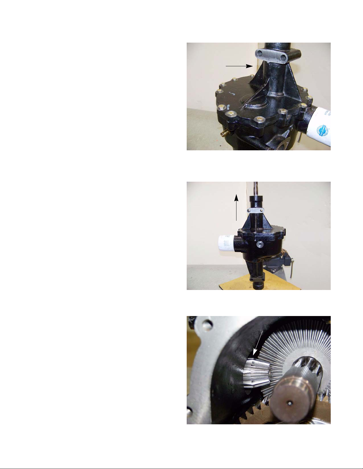
2000 Series Tractors
18. Remove the fourteen screws securing the left transmission housing to the right transmission housing
using a 1/2” wrench. See Figure 5.43.
19. Lift the left transmission housing off of the right
transmission housing. See Figure 5.44.
Left transmission
housing
Figure 5.43
20. Lay the transmission down on the work surface.
21. Remove patch bolt and washer securing the right
hub assembly to the right axle using a 1/2” wrench.
22. Slide the hub off of the axle shaf t.
23. Remove the 13T input pinion and ball bearing from
the right transmission housing using a wooden
dowel. See Figure 5.45.
NOTE: The 13T input pinion is pressed into the ball
bearing.
56
Figure 5.44
pinion gear
Figure 5.45
Page 63

Output shaft
Drive
24. Grasp the differential assembly and th e output shaf t.
See Figure 5.46.
25. Slowly pull the differential assembly and the output
shaft out of the right transmission housing un til the
output shaft is clear of the transmission.
26. Remove the 54T bevel gear and thrust washer from
the 9T output shaft.
Differential
Figure 5.46
Bevel gear
NOTE: The differential ring gear fits into the output shaft,
preventing it from being removed separately.
27. Continue removing the differen tial assembly from th e
right transmission housing. See Figure 5.47.
Figure 5.47
Figure 5.48
Ball bearings
28. Inspect both ball bearings in the right transmission
housing for wear or damage. See Figure 5.48.
57
Page 64
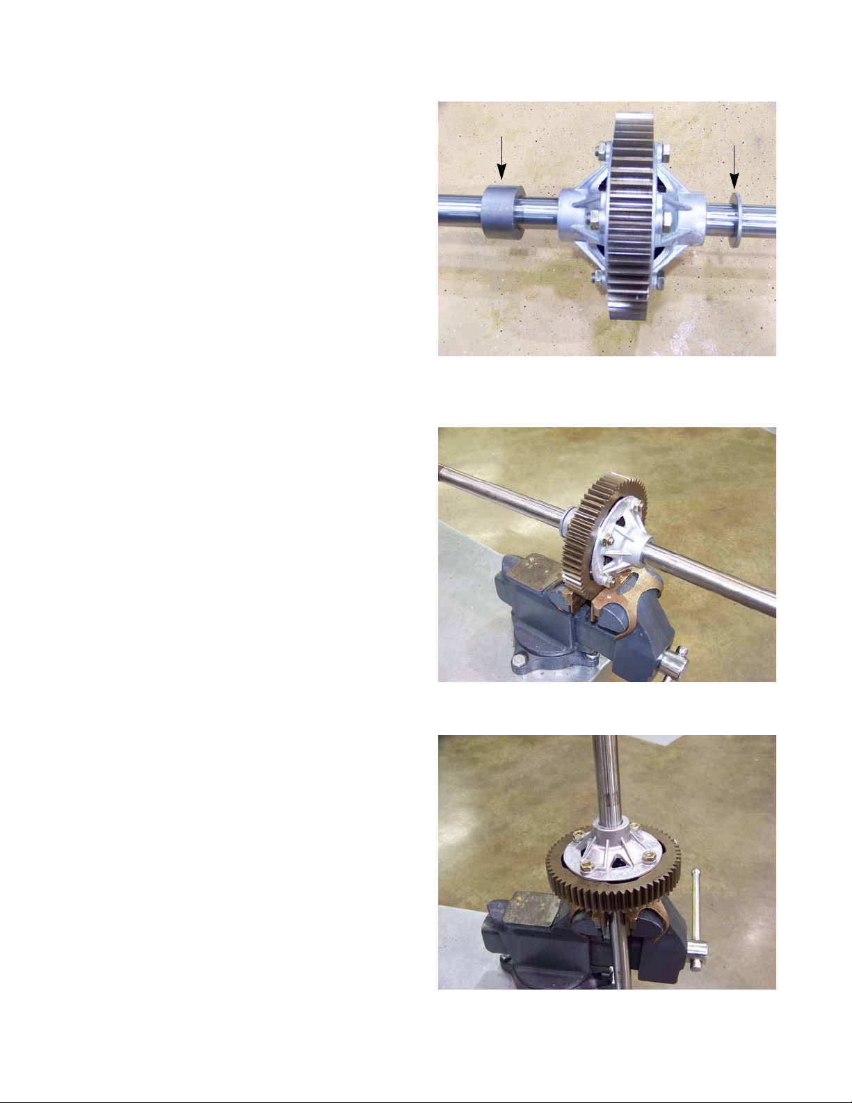
2000 Series Tractors
29. Remove the spacers from the differential axles.
See Figure 5.49.
NOTE: The short spacer goes on the axle towards
the right (deep) housing, and the longer
spacer goes on the axle towards the left
(shallow) housing.
NOTE: Mark the direction of forward rotation on the
spur gear. This will keep the worn in teeth
matched to the teeth on the output shaft.
30. Secure the 60T spur gear in a soft jawed vice.
See Figure 5.50.
31. Loosen the four hex bolts securing the differential
assembly together using a pair of 9/16” wrenches.
Long spacer
Short spacer
Figure 5.49
32. Secure the differential assembly in the vertical position, in the soft jaws of a vice, with the hex bolts facing up. See Figure 5.51.
33. Continue removing the hex bolts that hold the differential assembly together using a 9/16” wrench and
a shop rag.
58
Figure 5.50
Figure 5.51
Page 65

Spiral ring
Figure 5.52
Drive
34. Lift the left axle, differential housing, 14T miter gear
assembly off of the ring gear.
35. Separate the miter gear from the axle shaft by remo ving the pair of spiral lock rings. See Figure 5.52.
Axle shaft
Differential housing
Ring gear
Figure 5.53
Spider assembly
Miter gear
Spiral rings
36. Separate the differential assembly components and
inspect for damage or wear. See Figure 5.53.
37. Lift the ring gear and the spider gear assembly off of
the right axle assembly.
38. Separate the spider gear assembly and inspect for
damage or wear. See Figure 5.54.
39. Repeat steps 35 & 36 on the right axle assembly.
Figure 5.54
59
Page 66

2000 Series Tractors
40. Remove the oil filter from the right transmission
housing using an oil filter wrench. See Figure 5.55.
Oil filter
Figure 5.55
60
Page 67

Transmission Assembly
Drive
1. Remove any excess sealant from the transmission
housings mating faces.
2. Clean the mating faces of the transmission housings
using a scrubbing pad and alcohol. See Figure 5.56.
3. Install a new oil filter onto the right transmission
housing.
4. Secure the right axle, spiral retainer groove facing
up, in the soft jawed vice.
5. Set the threaded differential housing over the right
axle, cup facing up.
Clean with alcohol
Figure 5.56
8. Set the 60T spur gear in position on top of the threaded differential housing.
9. Assemble the differential assembly: cross-shaft and 10T miter gears.
10. Set the differential assembly into the 60T spur gear.
NOTE: There is no particular orientation for the differential assembly to be installed, but once broken-in, the
spur gear should be kept driven in its original direction.
11. Set the left axle assembly onto the differential assembly.
12. Secure the left axle assembly to the right axle as sembly with four hex cap screws using a 9/16” wrench.
6. Place the 14T miter gear onto the right ax le.
7. Secure the 14T miter gear to the axle with both spiral
retaining rings.
13. Secure the 60T spur gear in the soft jawed vice. See
Figure 5.57.
14. Tighten the four of the hex cap screws securing the
differential housings together to a torque of 220 - 280
in lbs (25 - 32 Nm).
15. Install the axle spacers up against the dif ferential
housing.
NOTE: The short spacer goes on the axle towards the
right housing, and the longer spacer goes on the
axle towards the left housing.
16. Begin to insert the differential assemblies right axle
into the right transmission housing.
Figure 5.57
18. Insert the output shaft, 54T bevel gear and thrust washer behind the differential assembly.
19. Slide the differential assembly and the output shaf t assem bly into the rig ht transm ission housin g and into thei r
respective ball bearings.
17. Place the 54T bevel gear and thrust washer onto the
9T output shaft.
61
Page 68

2000 Series Tractors
20. Place a 3/16” bead of Loctite
sealant around the perimeter of the right housing
mating face. See Figure 5.58.
21. Slide the left transmission housing over the left axle
assembly and set it into position, aligning the
mounting holes with the threads.
22. Apply a small amount of releasable thread locking
compound such as Loctite® 242 (blue) to the fourteen hex cap screws that hold the two transmission
halves together.
23. Install the fourteen hex cap screws and tigh ten them
to a torque of 150 - 210 in lbs (17 - 24 Nm).
NOTE: Torque all the hex cap screws securing the
transmission housings together in a cross
pattern.
24. Slide the hub assemblies onto the axle shafts.
25. Apply a small amount of releasable thread locking
compound such as Loctite® 242 (blue) to the wheel
hub patch bolts.
® Ultra Black or similar
3/16” bead of sealant
Figure 5.58
Patch bolt
26. Install the hub patch bolts and washer. Tighten
them to a torque of 260 - 350 in lbs (29 - 40 Nm).
27. Install the output shaft double lip seal using a seal
pusher and hammer. See Figure 5.60.
28. Apply anti-seize to the actuator pin contact surface
of the brake actuation arm.
29. Reassemble the brake assem b ly as fo llo ws: yoke,
actuation arm, torsion spring, flat washer, anti-rotation plate, lock nut, hex cap screws, actuation pins,
puck plate and brake pad.
30. Secure the brake assembly together using tape.
31. Insert the brake pad into the right transmission
housing.
Figure 5.59
Output shaft seal
32. Slide the brake disk over the output shaft.
NOTE: The center shoulder of the brake disk faces
outward.
62
Figure 5.60
Page 69

Drive
33. Secure the brake assembly to the right transmission housing with the hex cap screws using a 3/8” wrench.
NOTE: Tighten the brake assembly hex cap screws to a torque of 80 - 100 in lbs (9 - 11 Nm).
34. Adjust the brake pad clearance by following the procedures described in Chapter 3: Brakes.
35. Rotate the transmission so the filter is facing up.
36. Insert the 13T input pinion, ball bearing and spring washer.
37. Lubricate the gland seal and insert it into the right transmission housing.
NOTE: Grease the gland seal and its groove.
38. Set the BDU-10L and front torque bracket in position, aligning the mounting holes.
39. Insert two 5-1/2” screws through the front torque bracket, short spacers, BDU-10L and into the right transmission housing.
40. Insert two 5-1/2” screws through the front torque bracket, long spacers, BDU-10L and into the right transmission housing.
41. Tighten all four of the 5-1/2” screws to a torque of 220 - 280 in lbs (25 - 32 Nm) using a 1/2” wrench.
42. Lubricate the hydraulic inlet tube o-rings with grease.
43. Set the hydraulic inlet tube into position.
44. Secure the flare fitting of the hydraulic inlet tube to the BDU-10L. by hand.
45. Pivot the hydraulic inlet tube to the outlet port of the right transmission housing.
46. Loosely secure the hydraulic tube clamp and the lowe r e nd of the hyd raulic inle t tu be to the ri ght transmission
housing using a 7/16 in. socket.
47. Tighten the flair fitting of the hydraulic inlet tube to the BDU-10L using an 11/16 in. wrench.
48. Tighten the hex bolt securing the hydraulic tube clamp.
49. Install the oil drain plug with a 16mm wrench.
50. Install the transmission by following the procedures described in the transmission removal section of this chapter.
51. Fill the transmission with 182 oz (5.4 L) of Cub Cadet Drive System Fluid Plus oil (#737-3120)
NOTE: The Cub Cadet Drive System Fluid Plus oil (#737-3120) is a synthetic bl ended oil designed specifically
for Cub Cadet transmissions.
52. Purge the transmission while the tractor is still supported off of the ground.:
52a. Move the by-pass rod to the by-pass position.
52b. Start the engine.
52c. Cycle the drive pedal from full forward to full reverse six times.
52d. Move the by-pass rod to the drive position.
52e. Cycle the drive pedal from full forward to full reverse six times.
53. Perform a hydro neutral control adjustment by following the step s described in the hydro neutral contro l adjustment section of this chapter.
54. Test drive the tractor in a safe area before returning it to service.
63
Page 70

2000 Series Tractors
Symptom Root problem Mechanical cause Recommended action
Complete loss of
drive
Loss of control input Inoperative pedal linkage or
control arm not moving trunnion shaft
Loss of power to
hydro pump
Loss of hydraulic
pressure
Drive shaft and couplings to
engine and Transmission
Sheared input shaft at hydro
pump
Bypass valve open Check position of bypass con-
Low/no hydraulic fluid Check the transmission's dip-
Restricted flow to charge
pump
Visually inspect linkage and
force-check the control arm/
trunnion connection.
Inspect and force -check drive
shaft and coupling. May require
drive shaft removal.
Remove drive shaft and forcecheck input shaft (push/pull/
turn). May need to remove
charge pump cover to confirm
shaft rotation.
trol rod. Check for proper movement of the linkage and valve
plunger.
stick
Check external parts: pick-up
tube, fluid filter (Cub Cadet P/N
723-3014). NOTE: fluid & filter
replacement is a reasonable
first step
Loss of drive in Forward only
Mechanical drive failure
Loss of hydraulic
pressure in forward
circuit
Failed charge relief valve Remove and inspect charge
relief valve.
Failed charge pump Remove charge pump cover for
physical inspection
2 completely inoperative
charge check valves (very
unlikely scenario)
Pinion gear/bevel gear failure The brake rotor is on the same
Ring gear, differential, or axle
failure
Wheel hub not driven by axle Inspect and force-check wheel
Completely inoperative
charge relief valve
Remove and inspect charge
valves.
shaft that carries the bevel
gear. If the brake rotor turns in
response to drive inputs, but the
wheels do not, the problem is
down-stream of the bevel gear
See cell above
hub
Remove and inspect charge
check valves.
64
Page 71

Symptom Root problem Mechanical cause Recommended action
Drive
Loss of drive in
Reverse only
Sluggish operation,
no unusual noise
Loss of hydraulic
pressure in forward
circuit
Loss of control input Damaged Reverse pedal link-
Low engine speed. Mis-adjusted throttle or gover-
Linkage travel Binding or lost motion stack-
Wrong fluid or
blocked filter
Completely inoperative
charge relief valve
age
nor linkage, or engine performance issue.
up in pedal linkages prevents
full travel at hydro input arm.
Wrong fluid or blocked filter Change fluid filter if in doubt: fil-
Remove and inspect charge
check valves.
Check the operation of the
reverse pedal linkage. It transfers motion to the Forward
pedal linkage.
Check engine RPM and performance.
Check linkages for wear or
bind. Pay special attention to
the bushings that support the
pedal shafts. Pay special attention to the slotted adjustment
point in the drive control rod.
ter = Cub Cadet P/N 723-3014,
fluid = Cub Cadet Drive System
Fluid Plus P/N 737-3120 gallon.
NOTE: fluid & filter replacement
is a reasonable first step
Low pump output Worn hydro pump. Typically the hydro will work
fine when cold, but lose power
as it gets warm. Overheating
will aggravate the condition,
confirm that the transmission is
clean enough to dissipate heat
and that the cooling fan is
intact. NOTE: fluid & filter
replacement is a reasonable
first step
65
Page 72

2000 Series Tractors
Symptom Root problem Mechanical cause Recommended action
Sluggish operation,
hydraulic noise
Dragging brake Brake caliper not releasing Check the brake pedal and link-
age to the brake caliper. Check
brake adjustment. Check caliper operation.
Entrained air in system
Damaged pick-up tube or fitting leak at end of pick-up
tube.
Low fluid level Check dipstick. Symptoms may
Air leak near suction side of
charge pump. (Unlikely scenario)
System not purged after fluid
service
Charge relief valve leaking Remove and inspect charge
Bypass valve leaking Check linkage and plunger
Remove pick-up tube for
inspection and replace O-ring
seal. Bottom O-ring leak will
leave a puddle under the tractor. Top fitting leak will allow air
to be drawn-in.
be more pronounced on a
grade.
Charge pump housing may
show fluid leak
Purge system.
relief valve
movement on the by-pass
valve. Remove to inspect if necessary.
Charge check valve leaking Typically this will cause symp-
toms in one direction only. A
leaky Forward charge check
valve will effect performance in
Reverse. A leaky Reverse
charge check valve will cause
performance issues in Forward. NOTE: The forward
charge check valve is on the
right side of the hydro. pump.
The reverse charge check valve
is on the left side of the hydro.
pump.
66
Page 73

Manual Steering
CHAPTER 6A: MANUAL STEERING
Steering alignment
NOTE: Before performing a front end alignment, check for wear or dam age that might cause the misalignment
of the front wheels:
• Worn rod ends
• Bent drag links
• Loose steering arms or loose drag links
• Worn axles or king pin bores
• Worn wheel bearings
• Lift the front axle and spin each front wheel to check for excessive run-out.
NOTE: If there is run-out, find the midpoint of the run-out and use that point for your measurements.
• Repair as necessary before setting the toe angle.
NOTE: The front tires will have a “TOE-IN” between 1/16”
and 1/4” to allow the unit to track properly.
1 Check the air pressure in the front tires and make
certain that they are at approximately 14 PSI. The
rear tires should be at 10 PSI.
2. Park the tractor on level ground.
Pin punch
Figure 6A.1
"
#
Measure rim-to-rim at the front and back of rim
3. Lower the deck lift lever to the lowest position.
4. Turn the steering wheel to line up the centering hole
in the steering gear with the centering hole in the
support plate, and insert a 5/16” pin punch u p
through both. See Figure 6A.1.
NOTE: The steering wheel should be in the straight for-
ward position. If it is not, remove the steering
wheel and reinstall it so that it is.
5. In front of the axle, measure the distance (B) horizontally from the inside of the left rim to the inside of
the right rim. See Figure 6A.2.
6. From behind the axle, measure the distance (A) horizontally from the inside of the left rim to the inside of
the right rim.
Figure 6A.2
67
Page 74
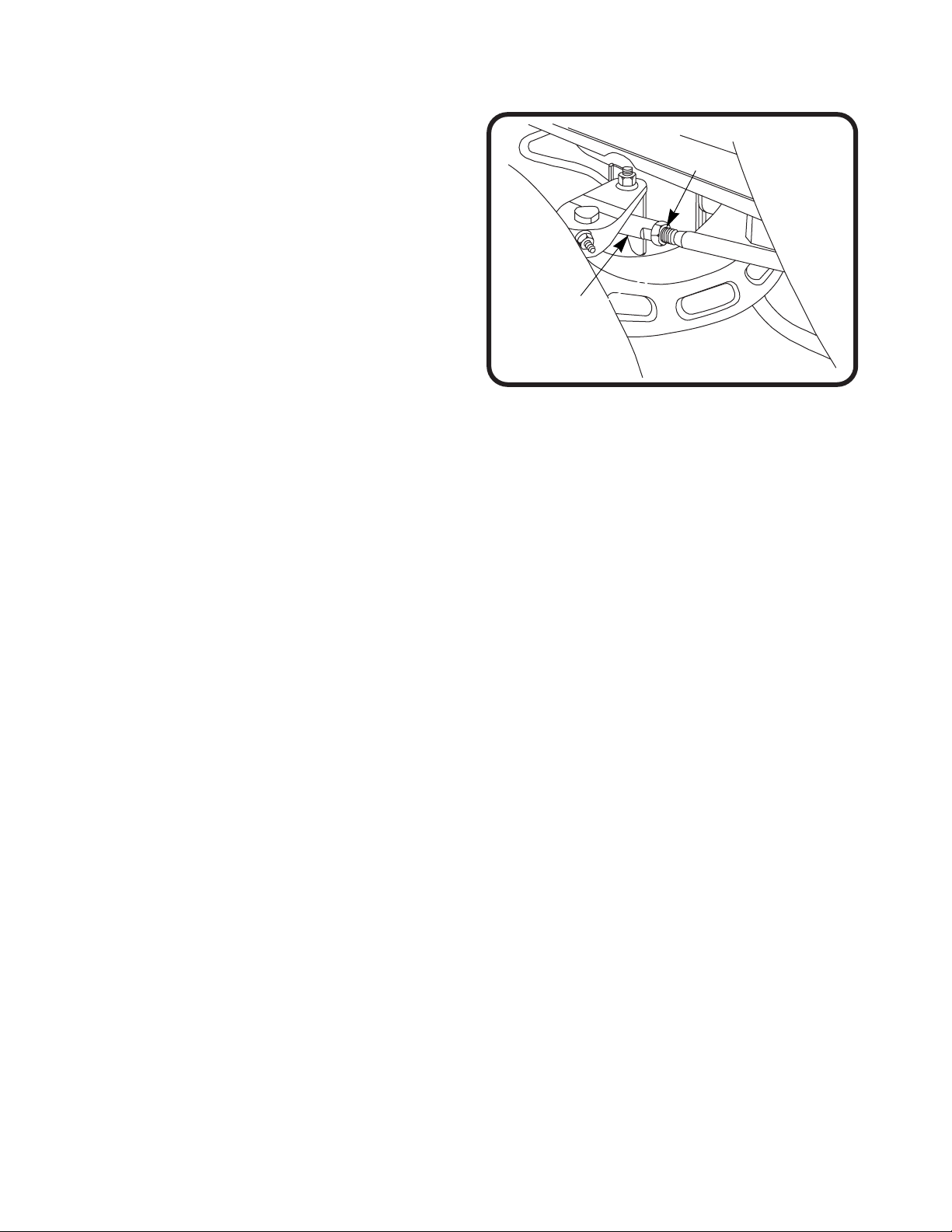
2000 Series Tractors
7. The measurement taken in front of the axle (B)
should be between 1/16” and 1/4” less than the
measurement taken behind the axle (A). If not, perform the following steps:
8. Loosen the jam nut at the rear of the right spherical
rod end using a 9/16” wrench and a n 1 1/16 ” wrench.
See Figure 6A.3.
Jam nut
9. Remove the nut, bolt and washer that secures the
right spherical rod end to the right axle assembly
using a pair of 9/16 wrenches.
10. Remove the right hand spherical rod en d fr om t he
right hand drag link.
11. Repeat steps 8, 9 and 10 on the left side.
12. Place the left and right tire assemblie s in the straight
forward position.
13. Set the toe-in for the rim assemblies to 3/16”.
14. Thread the right hand spherical rod end onto the right hand drag link until th e mounting hole in the right hand
axle assembly lines up with the hole in the spherical rod end.
NOTE: Count the number of turns the spher ical rod end was rot ated onto the drag link. This nu mber should b e
with in a couple of turns of the left sid e. If there is more than a couple turns difference, then one or both of the
drag links are bent.
15. Secure the right hand spherical rod end to th e right hand axle assembly with the nut, bo lt and washer removed
earlier, using a pair of 9/16” wrenches.
16. Secure the right hand spherical rod end jam nut to the right han d drag link using a 9/16” wrench and an 11/16”
wrench.
17. Install the left hand spherical rod end using steps 14, 15 and 16.
Spherical rod
Jam nut
end
Figure 6A.3
68
Page 75

Front wheels
Manual Steering
Remove/ replace the front wheels:
Hub cap
Figure 6A.4
Cotter pin
1 Lift and safely support the front end of the tractor.
2. Gently pry off the hub cap. See Figure 6A.4.
3. Remove and discard the cotter pin. See Figure 6A.5.
4. Remove the washer. See Figu re 6A.5.
5. Slide the wheel off of the axle.
Washer
Figure 6A.5
69
Page 76

2000 Series Tractors
Front wheel bearings
To replace the front wheel ball bearings:
1. Lift and safely support the front end of the tractor.
2. Remove the front wheel by following the procedures
described in the previous section of this chapter.
3. Drive the bearings out of the wheel hub using a
blunt ended punch. See Figure 6A.6.
4. Drive in the new bearings using a brass punch or a
suitable bearing driver that contacts only the outer
race. See Figure 6A.7.
5. Install the front wheel.
6. Pump grease in the grease fitting on the front wheel
until it starts to squirt out of the hub.
7. Test drive the tractor before returning it to service.
Ball bearing
Figure 6A.6
70
Figure 6A.7
Page 77
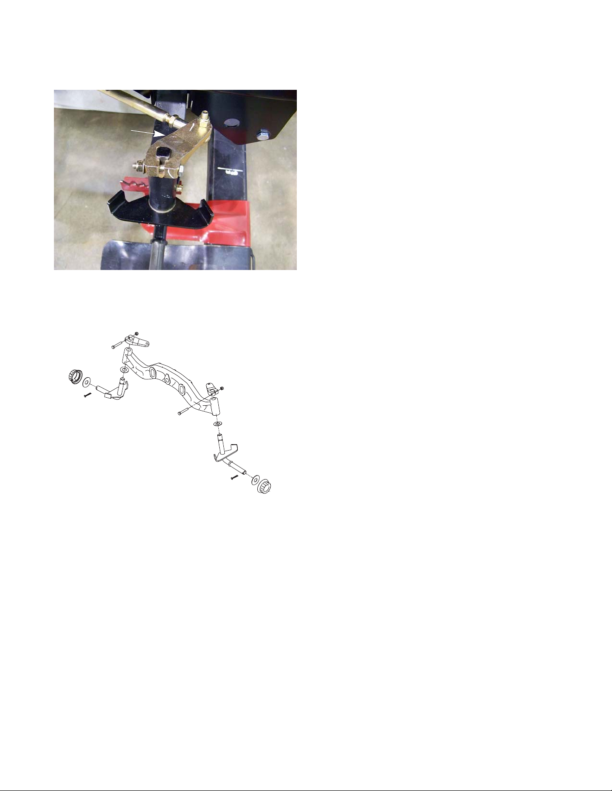
Axles
Steering arm
Manual Steering
NOTE: The axles used on the left side and right side are
the same part number.
1 Lift and safely support the front of the tractor.
2. Remove the front wheel by following the procedures
described in the front wheel section of this chapter.
3. Support the axle while loosening the nut and bolt
that hold the steering arm onto the axle using a pair
of 1/2” wrenches. See Figure 6A.8.
4. Lift the steering arm off of the axle.
5. Slide the axle out of the pivot bar.
Figure 6A.8
Figure 6A.9
6. Install the axle by following the previous steps in
reverse order.
NOTE: There is a washer between the axle flange and the
pivot bar. See Figure 6A.9.
7. Inject grease into the gr ea se fittin g of the ax le be ing
replaced until it oozes out.
8. Perform a wheel alignment by following the steps
described in the steering alignment section of this
chapter.
9. Test run the tractor in a safe area before returning it
to service.
71
Page 78

2000 Series Tractors
Steering sector gear and steering pinion gear
If you are replacing the steering sector gear or steering pinion gear, check the condition of both gears for any
wear or damage. It may be wise to replace both as a set.
If the steering gears show any unusual or accelerated wear, identify and correct the cause of the wear before replacing the gears. Possible causes of rapid wear include:
• Worn steering housing bores.
• Bent steering shaft.
• Worn sector gear pivot shaft.
• Binding drag links or axles (king pin).
• Broken travel stops
To remove/replace the steering gear s:
1. Remove the cutting deck by following the steps
described in Chapter 8: Cutting Decks and Lift Shaf t
2. Lift and safely support the front of the tractor.
3. Insert a 5/16” pin punch into the alignment hole to
lock the gears while removing the flange nut.
See Figure 6A.10.
4. Remove the flange lock nut securing the steering
pinion gear to the steering shaft using an 11/16”
socket. See Figure 6A.10.
5. Slide the steering pinion gear off of the steering
shaft.
6. Remove the bolt and washer , indicated by the arrow
in Figure 6A.11, that secures the steering sector
gear to the steering housing pivot shaft using a 1/2”
wrench.
Steering Pinion Ge ar
Flange Lock Nut
5/16” punch
Figure 6A.10
7. Slide the gear off of the shaft.
NOTE: The sector gear fits on a double-D shaft.
The shaft pivots in the steering housing.
72
Figure 6A.11
Page 79

Drag links
Figure 6A.12
Manual Steering
8. Disconnect the drag links from the forward most
holes in the sector gear using a 1/2” wrench and a 9/
16” wrench. See Figure 6A.12.
9. Install the steering gears by following the previous
steps in reverse order.
NOTE: Apply a small amount of releasable thread locking
compound such as Loctite® 242 (blue) to the sector gear bolt.
10. Inject grease into the grease fittings on the pivot bar
and the steering housing.
11. Perform a wheel alignment by following the steps
described in the steering alignment section of this
chapter.
12. Test drive the tractor in a safe area before returning
it to service.
73
Page 80

2000 Series Tractors
Steering shaft
To remove the steering shaft or to replace the hex
bushing:
1. Remove the cutting deck by following the steps
described in Chapter 8: Cutting Decks and Lift Shaf t
2. Lift and safely support the front of the tractor.
3. Remove the flange lock nut securing the steering
pinion gear to the steering shaft using an 11/16”
socket. See Figure 6A.13.
NOTE: If the steering shaft rotates while removing
the nut, insert a 5/16” pin punch into the
alignment hole in the steering gear. This will
lock the steering shaft in place, allowing the
nut to be removed.
Pinion gear
Pin punch
4. Slide the steering pinion gear off of the steering
shaft.
5. Remove the steering wheel
5a. Remove the cover from the center of the
steering wheel. See Figure 6A.14.
NOTE: The cover can be released by prying-in on
the lock-tabs on the under-side of the steering wheel. See Figure 6A.15.
Figure 6A.13
Figure 6A.14
5b. Remove the bolt that holds the steering wheel
to the steering shaft using a 1/2” wrench.
5c. Lift the steering wheel off of the steering shaft.
74
Figure 6A.15
Page 81

Manual Steering
NOTE: On tractors with power steering:
Steering shaft coupler
Figure 6A.16
• Loosen the lower nut and bolt of the steering shaft
coupler using a pair of 1/2” wrenches.
• Remove the top nut and bolt from the steering
shaft coupler. See Figure 6A.16.
NOTE: It may be necessary to drive the bolt out with a
punch.
6. Remove the two shoulder screws that hold the steering shaft collar to the tilt steering bracket using a 3/8”
wrench. See Figure 6A.17.
7. Lift the steering collar off of the tractor.
Steering dampener
Shoulder screws
Figure 6A.17
Cotter pin
Figure 6A.18
8. Remove and discard the cotter pin that secures the
tilt steering dampener. See Figure 6A.18.
75
Page 82

2000 Series Tractors
9. While holding the tilt steering bracket shoulder b olts
with a 3/4” wrench, remove the lock nuts using a 9/
16” wrench. See Figure 6A.19.
NOTE: The threaded section of the shou lde r bolts
are a “D” shaft. Applying torque to the bolts
will cause them to round over the “D” section, making it very difficult to get the bolt
out.
NOTE: On early production units, a large nut was
used as a s p a c e r o n t he right shou l d e r b o l t .
See Figure 6A.19.
Shoulder bolt
Figure 6A.19
NOTE: On current production models; there is an
adjuster plate attached to the tilt steering
bracket with a screw on each side of the
bracket. See Figure 6A.20.
NOTE: The adjuster plates can remain attached to
the tilt steering bracket.
Adjuster plate
Figure 6A.20
76
Page 83
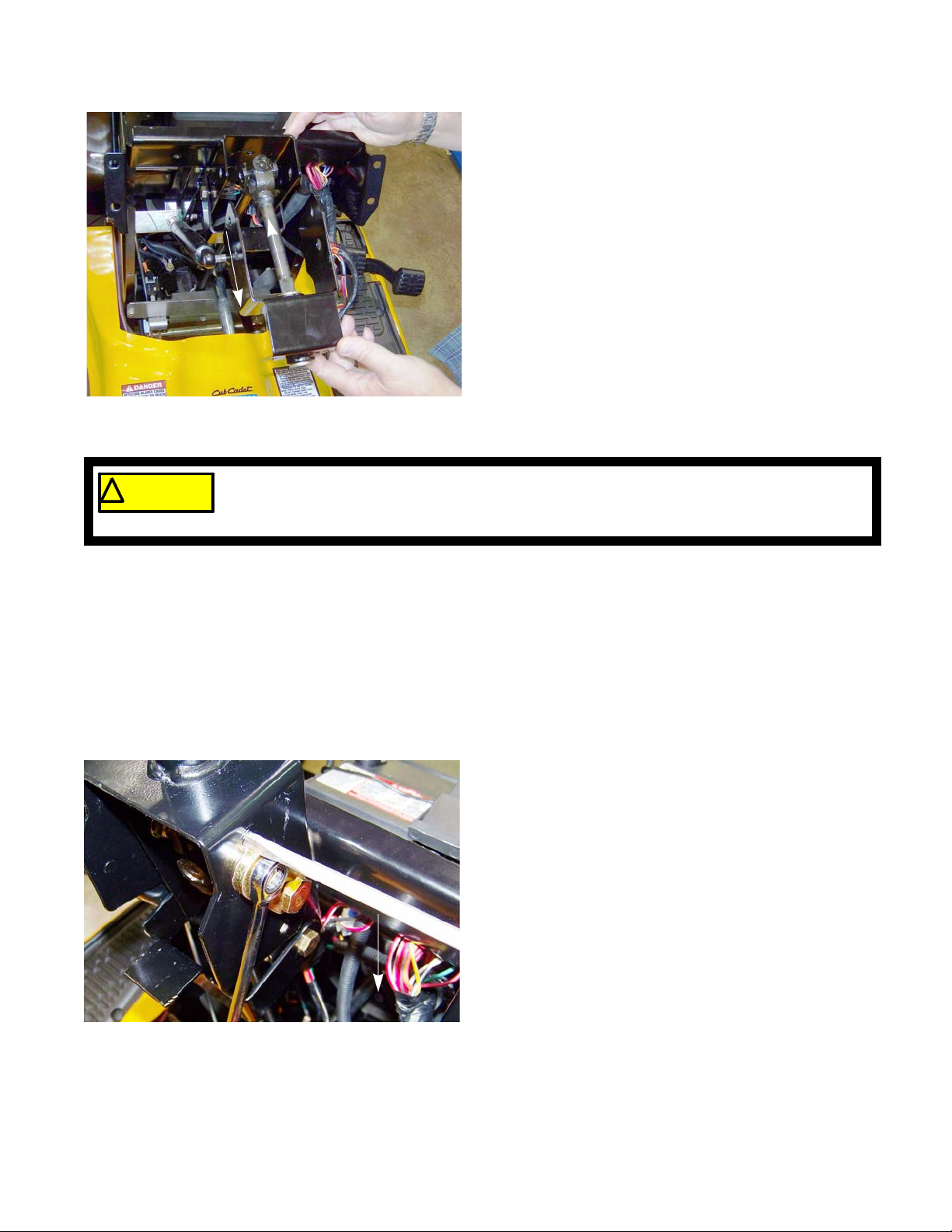
! CAUTION! CAUTION
Manual Steering
10. Slide the tilt bracket up and towards the rear of the
tractor enough that it clears the dash support tower.
11. Slide the tilt dampener off of the pin on the tilt
bracket.
12. Lift the tilt bracket and steering shaft off of the tractor.
NOTE: On tractors with power steering, it will probably be
necessary to pry the steering shaft coupler off of
the EPS assembly.
Figure 6A.21
DO NOT hammer on any of the EPS components.
Hammering on the EPS components can cause the calibration of the EPS to shift, resulting in
an auto-steer condition.
Manual steering
13. Lift the steering shaft out of the tractor.
Power steering
13. Slide the steering shaft out of the tilt steering br acket.
14. Install the steering shaft by following the above steps in reverse order.
NOTE: Tighten the shoulder bolt nuts to a torque of 240 - 350 (27 - 40 Nm)
15. Test run the tractor in a safe area before returning it to service.
NOTE: If the tilt steering is sloppy:
• Loosen the screw that holds the adjuster plate to
the tilt steering bracket using a 3/8” wrench.
• Insert a flat headed screw driver into the hole
above the adjuster plate. See Figure 6A.22.
• Pry down on the adjuster plate, driving it into the
shoulder bolt, while tightening the screw that hold
Pry down
the plate in place.
Figure 6A.22
77
Page 84

2000 Series Tractors
Pivot bar
1. Remove the deck and PTO belt by following the procedures described in Chapter 8: Decks and Lift Systems.
2. Lift and safely support the front of the tractor.
3. Remove the axles by following the procedures
described in the axle section of this chapter .
4. Slide the front deck link forward, out of the way.
See Figure 6A.23.
5. Support the pivot bar.
Front deck link
Figure 6A.23
6. Remove the two travel stop bolts using a pair of 9/
16” wrenches. See Figure 6A.24.
7. Remove the pivot bar pivot bolt using two 3/4”
wrenches.
8. Slide the pivot bar out of the frame.
9. Install the pivot bar by following the previous steps
in reverse order.
NOTE: Apply high quality grease to the frame and
the pivot bar.
10. Inject a high quality lithium base grease into all of
the grease fittings on the pivot bar.
11. Perform a wheel alignment by following the steps
described in the steering alignment section of this
chapter.
12. Test run the tractor in a safe area before returning it
to service.
Pivot bar bolt
Travel stop bolts
Figure 6A.24
78
Page 85

Steering housing
Manual Steering
To remove/replace the steering housing:
1 Remove the deck by following the procedures
described in Chapter 8: Decks and Lift Systems.
2. Remove the dash by following the procedures
described in Chapter 4: Body.
3. Remove the steering gears by following the procedures described in the steering gears section of this
chapter.
4. Remove the steering shaft by following the procedures described in the steering shaft section of this
section.
NOTE: On tractors equipped with power steering, remove
the EPS assembly by following the procedures
described in Chapter 6B: Electronic Power Steering.
Figure 6A.25
Figure 6A.26
Snap ring
5. Remove the four screws that hold the steering housing to the frame using a 1/2” wrench.
See Figure 6A.25.
6. Slide the parking brake latch br ac ke t and the ha rness to the side while lifting the steering housing o ut
of the tractor.
7. Remove the snap ring that holds the pivot shaft in
the steering housing. See Figure 6A.26.
8. Slide the steering housing pivot shaft out of the
steering housing.
9. Install the steering housing by following the previous
steps in reverse order.
NOTE: Coat the steering housing pivot shaft with an anti-
seize compound before inserting it into the steering housing.
NOTE: Make sure the ground strap connection to the
steering housing is clean and electrically sound.
10. Inject a high quality lithium base grease into all of the
grease fittings on the steering housing.
11. Perform a wheel alignment by following the steps
described in the steering alignment section of this
chapter.
12. Test run the tractor in a safe area before returning it
to service.
79
Page 86

2000 Series Tractors
Greasing the steering housing
The steering housing should be greased every 25
hours. To grease the steering housing:
1. Lift and safely support the front of the tractor.
2. Inject grease into the grease fitting at the steering
pinion gear until grease starts to ooze out.
See Figure 6A.27.
3. Lower the tractor to the ground.
Grease fitting
Figure 6A.27
4. Open the hood.
5. Inject grease into the grease fitting at the steering
housing pivot shaft until it starts to ooze out.
See Figure 6A.28.
NOTE: An 18” flexible extension hose for the
grease gun will make it easier to reach the
grease fitting.
Grease fitting
Figure 6A.28
80
Page 87

Electronic Power Steering
CHAPTER 6B: ELECTRONIC POWER STEERING
NOTE: The basic steering system, such as the tie rod ends, drag links axles, etc., are covered in Chapter 6A:
Steering.
In 2011, Cub Cadet introduced the Electronic Power Steering (EPS) system on the Cub GTX2154LE (50
versary edition) tractor. The EPS provides an electric assist to the steering wheel.
The EPS is a system consisting of three sub-assemblies: the rubber torsion coupling, the EPS module and
the EPS motor & gearbox. They form an assembly that is inserted between the steering shaft and the steering housing. The EPS system is treated as one part.
DO NOT loosen or separate any of
EPS Module
! CAUTION! CAUTION
sion coupler when the EPS assembly is built at
the factory . Once it has been calibrated, it can no t
be re-calibrated. Any shift between the coupling
and the module will result in the EPS auto-steering, which is a very unsafe condition.
the EPS components.
The module is calibrated to the tor-
th
anni-
EPS motor & gearbox
Rubber torsion coupling
Figure 6B.1
Rubber Torsion Coupling
The steering shaft connects the steer ing wheel to the EPS system through the rubber torsion coupling. As the
steering wheel is turned, it applies force to the coupling. The force causes the torsion coupling to twist or torque. The
amount the coupling torques is determined by the amount of force applied to the steering wheel, the more force
applied to the steering wheel, the more the coupling twists.
NOTE: The rubber torsion coupling has hard stops bui lt into it. If the force applied to the steering wheel causes
the coupling to hit its hard stops, the steering input will transfer through the module into the steering
gearbox. This allows manual steering if there is a failure of the EPS system.
EPS Module
The EPS module controls the power supplied to the EPS motor. It senses the amount of force that is being
applied to the steering wheel by monitoring the torsion coupling. The module will ramp up the power supplied to the
EPS motor as the force applied to the steering wheel increases. The EPS motor will reach full power within a couple
of degrees of deflection of the torsion coupling.
NOTE: Auto steering is a condition were
the EPS will turn the wheels to one
direction, once the engine is
started. This happens because the
calibration is off and the EPS thinks
there is a steering input when there
isn’t.
The EPS comes with a 4 year warranty. If there is
a failure with the system, replace the entire system as an assembly.
81
Page 88

2000 Series Tractors
EPS motor & gearbox
The steering input passes through the torsion co upling
and module into the gearbox. The gearbox then passes
the input force to the output shaft connected to the steering housing.
EPS module
The EPS motor assists in turning the input shaft by
driving a set of planetary gears. The planet ary gears drive
a worm shaft. The worm shaft drives a worm gear on the
output shaft.
IMPORTANT: DO NOT open or service the steering
gearbox.
DO NOT drop or hammer on any of
! CA UTION! CA UTION
trapped between the torsion coupling and the
EPS module. If this sensor shifts, it can cause an
auto-steer condition.
the EPS components.
There is a torque senor that is
Steering shaft
coupler
Torsion coupling
EPS motor
EPS motor
output shaft
EPS gearbox
Worm gear
Figure 6B.2
Planetary gears
Worm shaft
82
Worm gear
Figure 6B.3
Page 89

Troubleshooting the EPS
Electronic Power Steering
The first step in troubleshooting the EPS system is to
understand how it works. See Figure 6B.4.
,JQLWLRQPRGXOH
*5281'
0$*1(72
%$77(5<
Figure 6B.4
When troubleshooting the EPS system, The technician needs to isolate the problem to either the EPS assembly
or the circuits that go to the EPS assembly.
NOTE: To protect the EPS module, it will turn off if the steering input is held at a hard stop for more than 2 sec-
onds. The EPS will turn back on once the input is released from the hard stop.
• A constant 12 volts is supplied by the battery
through a 40 amp fuse in the fuse box.
• The EPS is grounded through the green wire.
• The EPS senses the ignition pulses from the ignition module primary windings throug h th e ye llow
wire with a white trace.
• Once the EPS determines that the engine is running (by sensing the ignition pulses from the ignition coil) it will turn on.
• The EPS will power the EPS motor as it senses
input from the steering wheel.
NOTE: Before troubleshooting any electrical circuit on a tractor, always make sure the battery is fully charged.
NOTE: The EPS assembly has constant battery power and is not controlled by the ignition switch.
To troubleshoot the EPS assembly:
1 Place the tractor on flat, level ground.
2. Remove any attachments that may be on the tractor.
3. Set the parking brake.
40 amp fuse
Figure 6B.5
4. Turn the steering wheel so that the wheels are p ointing straight forward.
5. With the ignition key in the off position, open the
hood.
6. Check the 40 amp fuse in the fuse box.
See Figure 6B.5.
NOTE: If the fuse is blown, replace the fuse and check for
a short in the red wire that goes to the EPS assembly.
83
Page 90

2000 Series Tractors
7. Locate, but do not disconnect the EPS harness connector behind the battery. See Figure 6B.6.
8. Check for battery voltage at the red wire:
8a. Set the Digital Multi Meter (DMM) to the DC
volts scale.
8b. Measure the battery voltage across the bat-
tery terminals
NOTE: If the battery voltage is < 12.6 volts, charge
the battery before continuing.
8c. Connect the black (-) lead of the DMM to the
negative post of the battery.
8d. Back probe EPS harness connector at the red
wire with a black trace, with the red (+) lead of
the DMM.
NOTE: The DMM should read battery voltage.
9. Check the ground to the EPS: See Figure 6B.7.
9a. Set the DMM to the DC volts scale.
9b. Connect the red (+) lead to the positive post of
the battery.
Green wire
Yellow wire
Red wire
Figure 6B.6
9c. Back probe EPS harness connector at the
green wire using the black (-) lead of the
DMM.
NOTE: The DMM should read battery voltage. If it
does not, disconnect the EPS harness. If
you now have battery voltage at the EPS
harness connector (tractor side), there is a
short in the EPS assembly. If not, repair the
tractor harness.
9d. Place an amp clamp meter on the red wire
with a black trace. See Figure 6B.8.
NOTE: Cut the tape that seals the loom at the EPS
connector end of the harness and slide the
loom off of the wires to attach the amp
clamp.
9e. Start the tractor.
NOTE: The voltage reading on the DMM should
now read over 13 volts. If it does not, repair
the charging circuit before proceeding with
troubleshooting the EPS system.
Figure 6B.7
Red wire/black trace
84
Figure 6B.8
Page 91

Electronic Power Steering
9f. Without sitting on the tractor, turn the steer ing whee l a q uarter turn ba ck a nd fo rth. Watching the voltage
reading on the DMM and the current reading on the amp clamp while doing this.
NOTE: If the voltage drops below 13 volts and the current does not rise above 10 amps, repair the circuit sup-
pling voltage to the EPS before proceeding with troubleshooting the EPS system.
NOTE: If the voltage drops below 13 volts and current draw is more than 10 amps, the problem is inside the
EPS assembly and it must be replaced.
9g. Turn off the tractor.
10. Check the input from the ignition module.
10a. Connect the ground lead of an oscilloscope to a
good ground on the engine block.
10b. Back probe EPS harness connector at the yel-
low wire with a white trace using the positive (+)
lead of the oscilloscope.
10c. Start the engine.
5 volt
reticle
Figure 6B.9
NOTE: A voltage spike over 18.5vdc +/- 1.2v @70°F will cause the volt age regulator to shut down. The regula-
tor must be disconnected, then re-connected to reset it.
NOTE: A sustained voltage over 25 volts will damage the EPS module.
NOTE: If the results are within the specified ranges or if the amperage draw is higher then expected, check for
a mechanical bind by:
14. Remove the steering pinion gear by following the procedures described in Chapter 6A: Steering.
15. Re-check the steering.
NOTE: If the steering now works, the pr oblem lies between the sector gear and the front wheels. A frozen axle
is a likely suspect.
16. Remove the EPS assembly.
NOTE: When removing the EPS from the steering housing, it should slide out easily. If it does not, repair the
steering housing before condemning the EPS.
11. The oscilloscope should show a pulsed signal. The
bottom or resting phase of each pulse must be below
5 volts. The peak of each pulse must be over 5 volts.
See Figure 6B.9.
12. The pulses must be at 9 Hertz (cycles/second) or
higher (engine needs to be >490 RPM).
13. If the resting phase of the pulse is above 5 volts,
there is a short in the safety circuit of the tractor that
is pulling up the voltage of the ignition module.
17. Check the steering shaft bushings.
NOTE: If the steering shaft is binding in the bushings, replace the bushings before condemning the EPS.
18. If nothing is in a bind, replace the EPS assembly.
85
Page 92

2000 Series Tractors
EPS motor
To remove/replace the EPS motor and test it:
NOTE: The EPS system comes with a 4 year war-
ranty. DO NOT remove the EPS motor to
test it within the warranty period. Outside of
the warranty period, the EPS motor can be
replaced separately from the EPS assembly.
1. Remove the EPS assembly by following the procedures described in the EPS removal section of this
chapter.
2. Disconnect the EPS motor harness.
3. Remove the two screws, indicated by the ar ro ws in
Figure 6B.10, that secure the motor base to the
EPS using a 3/8” wrench.
4. Lift the motor assembly off of the EPS.
5. Mount the motor in a vise.
NOTE: Position the motor so that the vise jaws
clamp the motor base, to prevent damage to
the motor.
6. Attach the black wire from the motor to the negative
side of a 12 volt power supply capable of producing
40 amps.
NOTE: The tractor’s battery or a jumper box can be
used as a power supply.
7. Attach the red wire from the motor to the positive
side of the power source.
NOTE: The motor should spin. If it does not, replace
the motor.
Figure 6B.10
Red wire
Black wire
Figure 6B.11
86
Page 93
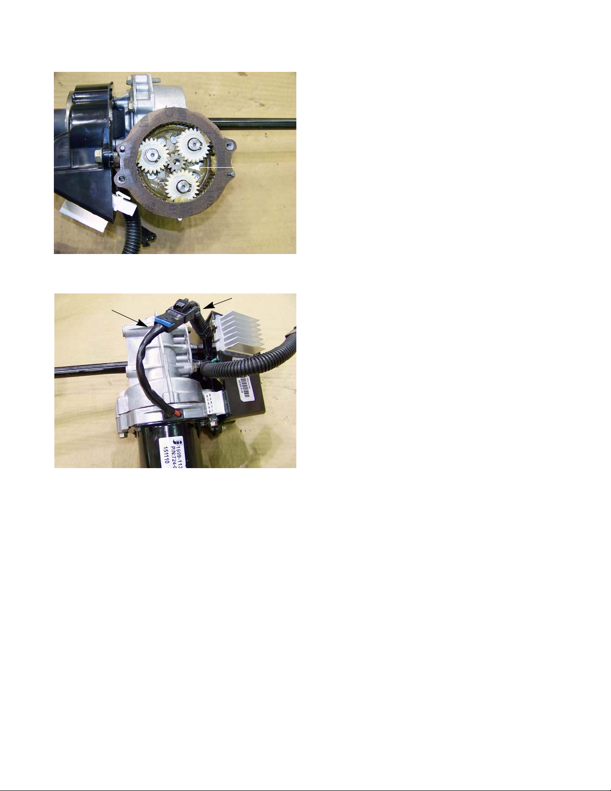
Figure 6B.12
Sun gear
Electronic Power Steering
8. Inspect the EPS motor gasket. If it is damaged,
replace it.
NOTE: Do not use a gasket sealant/adhesive on the EPS
motor gasket.
9. Remove the sun gear from the EPS motor.
10. Install the sun gear into the planetary gear set.
EPS motor pig tail
Harness
11. Install the EPS motor.
NOTE: While installing the EPS motor, align the motor pig
tail with the EPS motor harness.
12. Install the EPS assembly in the tractor by following
the procedures described in the EPS removal section of this chapter.
13. Test run the tractor in a safe area before returning it
to service.
Figure 6B.13
87
Page 94

2000 Series Tractors
EPS removal/replacement
1. Open the hood.
2. Remove the battery: See Figure 6B.14.
2a. Disconnect the negative battery lead.
2b. Disconnect the positive battery lead.
2c. Remove the screw that secures the battery
hold down to the battery tray using a 3/8”
wrench.
2d. Swing the battery hold down out of the way.
2e. Remove the battery from the tractor.
Battery
Figure 6B.14
3. Remove the dash by following the procedures
described in Chapter 4: Body.
4. Thread the screw from the steering wheel into the
steering shaft with a fender washer.
See Figure 6B.15.
NOTE: The screw and fender washer will keep the
steering shaft from falling out while lifting the
dash support off of the tractor.
5. Remove the three screws, indicated by the arrows
in Figure 6B.16, that secure the lower baffle to the
frame and dash support using a 3/8” wrench.
Fender washer
Figure 6B.15
88
Baffle
Figure 6B.16
Page 95
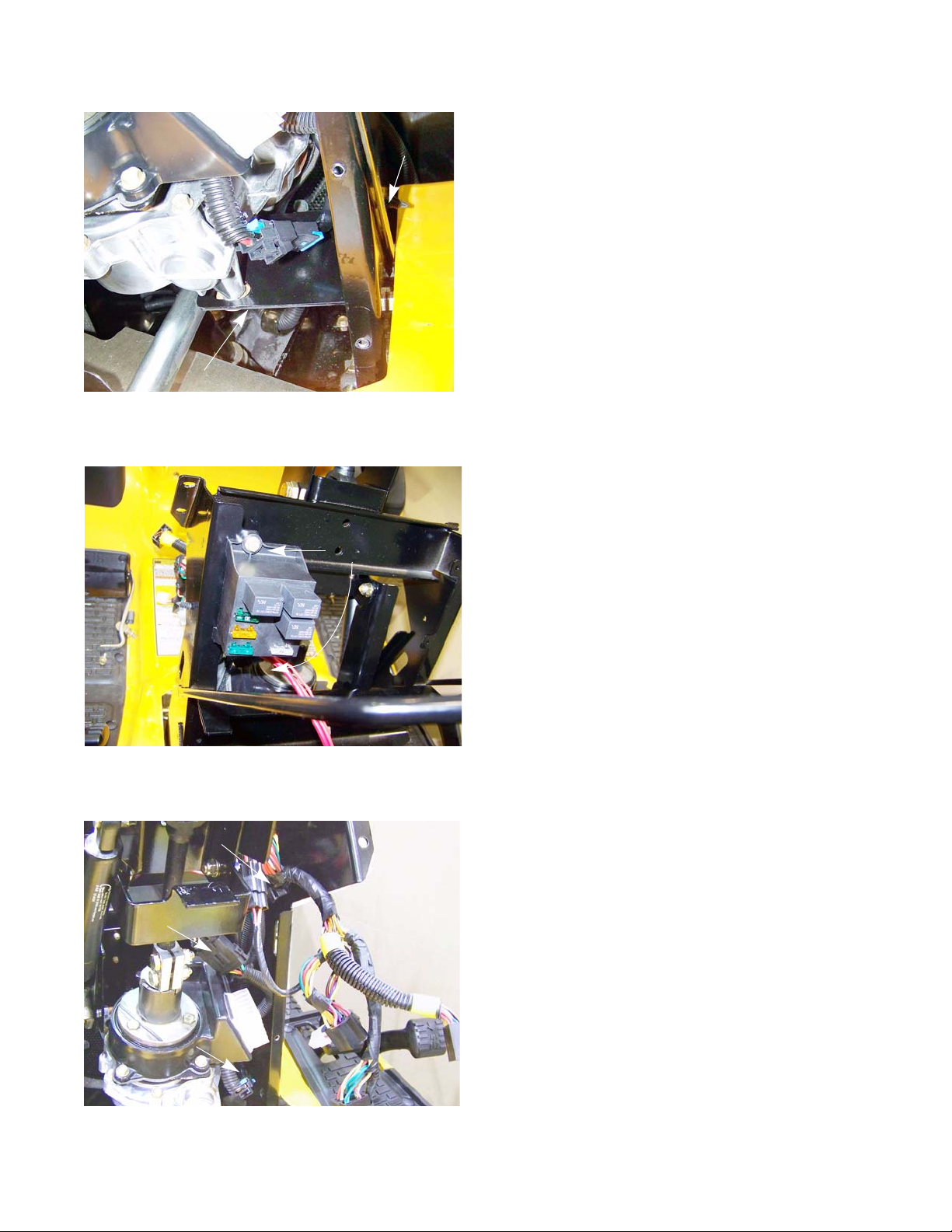
Electronic Power Steering
Support bracket
Figure 6B.17
Screws
Tappet
wrench
6. Remove the EPS support bracket:
6a. Remove the two screws and washers that hold
the support bracket to the EPS using a 1/2”
wrench
6b. Remove the two nuts and bolts that secure the
bracket to the dash support using a pair of 1/2”
wrenches.
NOTE: A thin wrench, such as a tappet wrench can be slid
between the fender and the dash support to hold
the bolt heads. See Figure 6B.17.
7. Slide the support bracket out of the tractor.
8. Remove the two screws that hold the fuse box to the
dash support using a 3/8” wrench. See Fi gure 6B.1 8.
Harness clamp
EPS connector
Cable clamp
Figure 6B.18
9. Open the two harness clamps that hold the main
harness to the dash support. See Figure 6B.19.
10. Unplug the EPS harness connector.
11. Unweave the harness from the dash support and let
it lay on the fender, pointing towards the seat.
Figure 6B.19
89
Page 96

2000 Series Tractors
12. Remove the cotter pin that secures the cruise control rod to the latch. See Figure 6B.20.
NOTE: There is a spring attached to the cruise rod
that will come off when the cotter pin is
removed.
13. Remove the cruise control rod.
14. Remove the screws, two on each side of the tractor ,
that hold the dash support to the frame rails using a
1/2” wrench. See Figure 6B.21.
Cruise control rod
Spring
Latch
Figure 6B.20
15. Remove the four screws, indicated by the arrows in
Figure 6B.22, that hold the dash support to the
steering sub-frame using a 1/2” wrench.
Screws
Figure 6B.21
90
Figure 6B.22
Page 97

Figure 6B.23
Steering shaft
coupler
Electronic Power Steering
16. Loosen the top nut and bolt of the steering shaf t coupler using a pair of 1/2” wrenches.
17. Remove the lower nut and bolt from the steering
shaft coupler. See Figure 6B.23.
NOTE: It may be necessary to drive the bolt out with a
punch.
18. Lift the dash support off of the tractor, taking the
steering shaft with it.
NOTE: It will probably be necessary to pry the steering
shaft coupler off of the EPS.
DO NOT hammer on any of the
! CAUTION! CAUTION
nents can cause the calibration of the EPS to
shift, resulting in an auto-steer condition.
EPS components.
Hammering on the EPS compo-
Washer
5/16”pin punch
Figure 6B.24
Pinion gear
19. Lock the steering by inserting a 5/16” pin punch into
the alignment hole of the steering sector gear and
the steering housing. See Figure 6B.24.
20. Remove the nut that secures the pinion gear to the
EPS output shaft using an 11/16” wrench.
21. Remove the pinion gear.
NOTE: There is a flat washer between the pinion g ear and
the steering housing. This washer will be trapped
between the sector gear and the EPS output shaft.
Once the EPS is lifted out of the tractor, the
washer will fall to the ground.
91
Page 98

2000 Series Tractors
NOTE: Lift the EPS out of the tractor.
NOTE: The EPS output shaft will pass through a
spacer, washer and the steering housing.
See Figure 6B.25.
NOTE: Install the EPS by following the previous
steps in reverse order.
NOTE: The washer that goes in between the pinion
gear and the steering housing, must be held
in place under the tractor while inserting the
EPS into the steering housing.
22. Test drive the tractor in a safe area before returning
it to service.
Spacer
Washer
Figure 6B.25
92
Page 99

CHAPTER 7: ELECTRICAL SYSTEM
Introduction
This chapter is divided into four sections:
• Section 1: About this chapter and precautions
• Section 2: Components
• This section will describe the location and operation of the electrical components on the mower. Where
appropriate, some disassembly or component removal instructions will be included.
• Section 3: Diagnostic Techniques
• This section will cover basic tools, techniques, and methodology for diagnosing electrical issues on the
mower. A lot of the information in this section can be applied to other equipment.
• Section 4: Schematics
Before disconnecting any electrical component, take precautions to prevent the component or
! CA UTION! CA UTION
the wires attached to it from shorting out. The mo st effective means of doing th is is to disconnect
the battery ground cable from the negative battery terminal. Unless performing test s that require
the electrical system to be in operation, disconnect the negative cable from the battery before
doing any work to the electrical system of the mower.
Electrical System
Components
The 2000 series tractors have the same Cub Cadet Rev-Tek system used on the 1000 series tractors.
RMC Module
The RMC module contains elect ron ic logic circuits. When diagnosing anything that is connected to the RMC
module, a high impedance test light or a high impedance digital multi-meter (DMM) must be used. The amperage
draw of a standard incandescent test light may over-burden some internal electronic circuits, burning out the module.
NOTE: These tools are not outrageously expensive or exotic. High impedance test lights (Thexton model 125
is typical) can be purchased locally from stores like NAPA for under $30.00. Appropriate multi meters can be
purchased for under $100.00, and are an invaluable tool for any competent technician.
• It is typical when industries shift from electromechanical to electronic controls that diagnosis shifts from
tracing through a number of independent circuits to checking the in-puts to and out-puts from a central
processor. This is similar to, but much less complex than the transition that the auto industry made with
the conversion to fuel injection in the 1980s.
NOTE: The starter safety circuit has no connection to the RMC module.
• It is still important to be familiar with the workings of the individual component s of the electrical system, but
some of them can now be checked from a central point on the mower. This makes life easier on the technician, frequently making it unnecessary to connect to difficult to reach switches in the preliminary stages
of diagnosis.
• The function of individual safety switches can be seen as providing information “inputs” to the RMC module.
• The next part of this section gives a detailed description of the electrical components on this mower, their
function in the system, and their physical location on the mower. Armed with this information and the
proper tools, a technician should be able to efficiently diagnose most electrical problems.
93
Page 100

2000 Series Tractors
Key switch
The Key Switch is similar to those used in a variety of
MTD applications since 1999. The differ ence , in this case,
is that it is incorporated in the same housing as the RMC
module. The two items are not available separately.
See Figure 7.1.
1. In the “OFF” position, continuity can be found
between the M, G, and A1 terminals.
See Figure 7.2.
• M is connected to the magneto by a yellow
wire, G is connected to ground by a green wire,
and A1 is connected to the afterfire solenoid.
NOTE: In the “OFF” position, the magneto primary
windings are grounded, disabling the ignition system. The afterfire solenoid loses its power from the
B terminal. This turns off the fuel supply.
NOTE: The A1 terminal is shorted to ground when the key is moved to the “OFF” position. This is a legacy feature from older tractors that had the afterfire solenoid pow ered directly from the alternator. This feature in not
needed on current production tractors.
Front
RMC Module
Key
Switch
Back
Figure 7.1
• Symptom: loud “BANG” when key is turned to
the OFF position: The afterfire solenoid is not
closing, either because it is physically damaged
or the power is not being turned off. Check for
power at the solenoid. Check continuity
between G and A1 terminals. Check for no continuity between A1 and the B terminals.
NOTE: If the engine is at an idle when the key is
turned off, fuel is drawn into the engine through the
idle ports of the carburetor by-passing the fuel shut
off solenoid. The raw fuel will travel through the
engine and ignite in the muffler causing an afterfire.
• Symptom: Engine runs 3-5 seconds after key
is turned to OFF position: The afterfire solenoid
is turning off the fuel supply, but the ignition is
continuing to operate. Check continuity
between the M and G terminals in the OFF
position. Check continuity from yellow wire connection all the way to the spade terminal on the magneto.
2. In the START position, continuity can be found between B, S, and A1 terminals.
• Battery power from the B terminal is directed to the start circuit through the S terminal and to the afterfire
solenoid through A1.
• Symptom: No crank and no starter solenoid click
solenoid. Test for a fully charged battery, then check for power where the fused red wire with white trace
connects to the B terminal. Check for continuity between B and S terminals in START position. If power is
getting to the S terminal in the START position, the problem lies down-stream in the starter circuit. Check
continuity from the orange wire on the S terminal to the orange wire with white trace on the trigger spade
on the starter solenoid. If it is broken, trace through the brake and PTO switches.
: Power is not getting to the trigger spade on the starter
.H\VZLWFKVFKHPDWLF
%
6
/
0
/
0
5XQZ50&
6
$
2II
$
*
$
%
*
$
Figure 7.2
%
6
/
0
$
6WDUW
6
$
%
/
0
1RUPDOUXQ
$
$
*
*
• Symptom: No crank, solenoid click
battery voltage, battery cables, starter cable, solenoid, or ground issue.
94
: The problem lies in the heavy-gauge side of the starter circuit: low
 Loading...