

Page 1
Update Manual
2005-2 200 Series Snow Thrower Update
NOTE: These materials are for use by trained technicians who are experienced in the service and repair of outdoor power
equipment of the kind described in this publication, and are not intended for use by untrained or inexperienced individuals.
These materials are intended to provide supplemental information to assist the trained technician. Untrained or inexperienced individuals should seek the assistance of an experienced and trained professional. Read, understand, and follow all
instructions and use common sense when working on power equipment. This includes the contents of the product’s Operators Manual, supplied with the equipment. No liability can be accepted for any inaccuracies or omission in this publication,
although care has been taken to make it as complete and accurate as possible at the time of publication. However, due to
the variety of outdoor power equipment and continuing product changes that occur over time, updates will be made to these
instructions from time to time. Therefore, it may be necessary to obtain the latest materials before servicing or repairing a
product. The company reserves the right to make changes at any time to this publication without prior notice and without
incurring an obligation to make such changes to previously published versions. Instructions, photographs and illustrations
used in this publication are for reference use only and may not depict actual model and component parts.
© Copyright 2005 MTD Products Inc. All Rights Reserved
MTD Products Inc - Product Training and Education Department
FORM NUMBER - 769-02087
10/2005
Page 2

Page 3

TABLE OF CONTENTS
Introduction ........................................................................................................................... 1
Drive Belt Removal ............................................................................................................... 1
Auger Removal ..................................................................................................................... 2
Rubber Auger Spiral Replacement ....................................................................................... 3
Cable Removal ..................................................................................................................... 4
Fuel Tank Removal ..............................................................................................................5
Engine Support Bracket ....................................................................................................... 6
Four-Cycle Models ............................................................................................................... 7
1
Page 4

2
Page 5

200 Series Single Stage Snow Throwers
200 Series Single Stage Snow Throwers
1. INTRODUCTION
1.1. For the 2005-2 manufacturing year several
changes have been made to the single stage
snow throwers.These changes are detailed in
this section of the manual.
1.2. Disclaimer: This service manual was intended
for use by trained technicians.The information
contained in the manual is current and accurate
at the time of writing, but is subject to change
without notice.
1.3. Description: The 200 series single stage snow
thrower is designed with the typical residential
user in mind.The snow blower weighs approximately 70lbs and is compact enough to store in
smaller areas. This machine is equipped with a
2-cycle Tecumseh Snow King engine.Similar
models are also powered with 4-cycle Tecumseh
engines. See Figure 1.3.
2. DRIVE BELT REMOVAL
2.1. Remove the 5 perimeter screws using a 3/8”
wrench or socket. See Figure 2.1.
Shorter Perimeter
Screw
Perimeter Screws
Figure 2.1
2.2. The front screw used in holding the belt cover on
is shorter than the other four and is a fine
thread.It is necessary that this screw be used to
allow for clearance to the auger assembly. See
Figure 2.2.
MODEL #
31A-240-800
Figure 1.3
NOTE: Before servicing, or repairing the snow
thrower. Stop engine and wait until the engine
has cooled.Disconnect the spark plug and
ground it to the engine to prevent unintended
starting.
Clearance
Figure 2.2
1
Page 6

200 Series Single Stage Snow Throwers
2.3. In the disengaged position it is possible to roll
the belt off the bottom of the auger pulley. See
Figure 2.3.
New Idler
Bracket
2.4. This will provide enough slack to roll the belt off
of the engine pulley.
2.5. Press down onto the idler pulley bracket to
release the auger brake remove the belt from
the machine. See Figure 2.5.
New Idler
Pulley
Figure 2.3
Auger Brake
3. AUGER REMOVAL
3.1. Remove the drive belt as described in drive belt
removal
3.2. Using a 1”socket twist off the auger pulley. See
Figure 3.2.
Figure 3.2
NOTE: The pulley is held the auger shaft with
with left hand threads.
NOTE: The imagine shows the Idler bracket
removed However, this can be performed with
the Idler bracket in place.
3.3. Detach the left side bearing housing by removing the three screws with a 3/8”wrench.
See Figure 3.3.
Figure 2.5
NOTE: There has been a slight change to the
Idler bracket from last years production.
NOTE: Anytime its necessary to change a belt it
is a good opportunity to inspect the cable, or
springs for any signs of wear.
Figure 3.3
2
Page 7

200 Series Single Stage Snow Throwers
3.4. Remove the bearing housing and bearing from
the auger shaft. See Figure 3.4.
Figure 3.4
NOTE: The left side (Drive Side) has a washer
located between the auger housing and bearing.
3.5. Remove the three screws holding the right side
bearing housing on with a 3/8” wrench.
3.6. Remove the right side auger bolt with a 7/16”
wrench. See Figure 3.6.
3.7. Remove the auger by sliding it to the left side of
the housing and tilting the right side out. See
Figure 3.7.
Figure 3.7
3.8. After the short end of the auger shaft has been
removed, there will be enough clearance to withdraw the long threaded end of the shaft from the
housing
4. RUBBER AUGER SPIRAL REPLACEMENT
4.1. Lean the snowblower back so that it rests on its
handlebars. See Figure 4.1.
Figure 3.6
NOTE: The rubber spirals and flats can be
replaced without removing the auger from the
housing
Figure 4.1
4.2. Remove the 20 self tapping screws attaching the
rubber spirals and flats to the auger assembly
using a 3/8” wrench.
4.3. Attach new auger spirals to the auger assembly.
3
Page 8

200 Series Single Stage Snow Throwers
5. CABLE REMOVAL
5.1. Remove the belt cover as described in the belt
removal section of this manual to expose the
Idler bracket. See Figure 5.1.
Figure 5.1
NOTE: It is necessary to remove the idler
bracket to remove the cable.
5.2. disconnect the return spring. See Figure 5.2.
5.3. Remove the bolt that the idler bracket pivots on
using two 1/2” wrenches. See Figure 5.3.
Figure 5.3
NOTE: The idler pulley is new for the 2005 man-
ufacturing season.
5.4. Disconnect the cable from the idler bracket.
5.5. Loosen but DO NOT remove the bolt that holds
the cable guide pulley onto the frame with one 7/
16” wrench on the outside of the housing and
one 7/16” wrench on the inside of the housing.
See Figure 5.5.
Figure 5.2
NOTE: The return spring also acts as a brake
engagement spring.
Figure 5.5
4
Page 9

200 Series Single Stage Snow Throwers
5.6. Pinch the tabs on the cable housing with a pair
of needle nose pliers to free it from the holder on
the frame. See Figure 5.6.
Figure 5.6
5.7. Cut the cable tie to release the cable from the
handle bars. See Figure 5.7.
5.8. If the cable is to be reused carefully disconnect
the retainer clip from the handle bar.
See Figure 5.8.
Figure 5.8
5.9. Disconnect the Z-fitting from the bail.
5.10. Install new cable.
6. FUEL TANK REMOVAL
Figure 5.7
6.1. Remove the upper chute and chute handle from
the lower chute. See Figure 6.1.
Figure 6.1
5
Page 10
200 Series Single Stage Snow Throwers
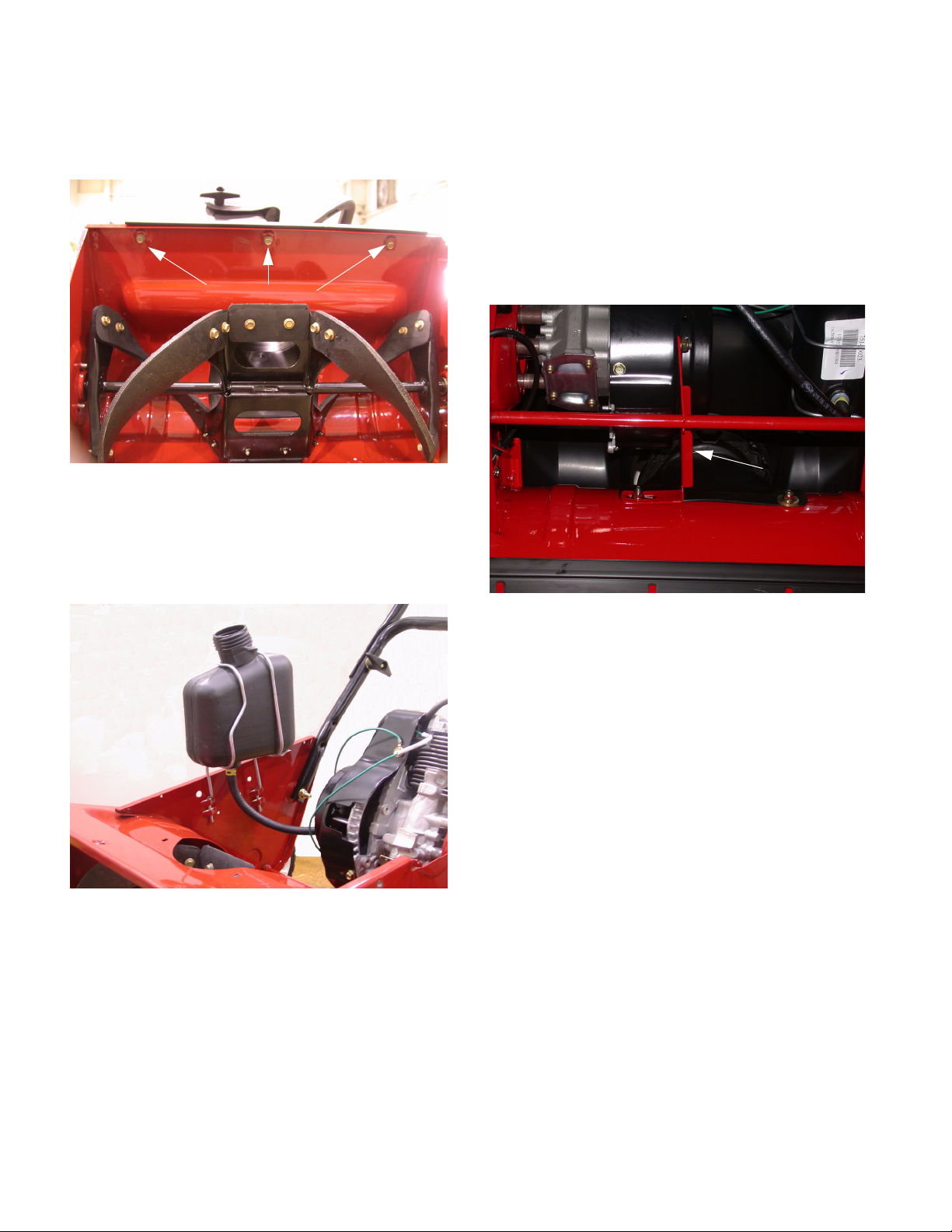
6.2. Remove the three screws securing the front of
the shroud to the auger housing using a 3/8”
wrench.
Shroud Screws
Figure 6.2
6.3. Remove 4 screws (2 on each side) securing the
shroud to the frame.
6.4. Lift the fuel tank up along withe wire brackets
that are weaved in slots on the side of the frame.
7. ENGINE SUPPORT BRACKET
7.1. Although any engine related issue would be
resolved through the engine manufacturer it is
important to be aware of changes in how the
engine is secured in the machine.
7.2. A new support bracket is used to add additional support from its previous predecessor.
See Figure 7.2.
Engine support bracket
Figure 7.2
Figure 6.4
NOTE: If there is fuel in the fuel tank it will be
necessary to pinch off the fuel line and disconnect the fuel line from the carburetor.
NOTE: To provide a clear view of the fuel tank
bracket the lower chute was removed.
6
Page 11

8. FOUR-CYCLE MODELS
8.1. Some of the MTD single-stage snow throwers
are powered by four-cycle Tecumseh Snow King
Engines. They are very similar to the two-cycle
version except for the engine and its mounting
brackets. See Figure 8.1.
Oil Fill Cap
200 Series Single Stage Snow Throwers
Figure 8.1
8.2. The four-cycle models are easily recognized by
the presence of a yellow oil-fill cap and dipstick,
protruding through the shroud.
8.3. A four-cycle snow thrower is an appropriate
choice when:
• A customer is averse to the noise produced by a
two-cycle engine
• A customer is not comfortable mixing gas and
oil.
8.4. A two-cycle snow thrower is an appropriate
choice when:
• The customer lives where temperatures are
extremely cold and the snow thrower may not be
protected from those temperatures. There is no
oil-viscosity to over-come when starting a twocycle engine.
• The customer requires a more easily portable
snow thrower: two-cycle engines are lighter than
four-cycle engines. The weight of the engine
accounts for a large part of the total weight of
these relatively simple snow throwers.
• The customer may have cost restraints preventing them from acquiring an larger model.
7
 Loading...