

Page 1
Hydrostatic Zero-Turn
0
Commercial Riding Mower
Professional Turf Equipment
MODEL
19HP Tank, 53BB5DAV150
20HP Tank, 53AB5E6V150
23HP Tank, 53BB5DBW15
24HP Tank, 53AB5ETW150
25HP Tank, 53AB5D8X150
27HP Tank, 53AB5BDX150
28HP Tank, 53AB5FEZ150
OPERATOR’S AND SERVICE MANUAL
Page 2

TABLE OF CONTENTS
Foreword. . . . . . . . . . . . . . . . . . . . . . . . . . . . . . . . . . . . . . . . . . . . . . . . . . . . . . . . . . . . . . . 3
General Safety Operations. . . . . . . . . . . . . . . . . . . . . . . . . . . . . . . . . . . . . . . . . . . . . . . . . 4
A.Danger . . . . . . . . . . . . . . . . . . . . . . . . . . . . . . . . . . . . . . . . . . . . . . . . . . . . . . . . . . 4
B.Warning . . . . . . . . . . . . . . . . . . . . . . . . . . . . . . . . . . . . . . . . . . . . . . . . . . . . . . . . . 4
C.Caution . . . . . . . . . . . . . . . . . . . . . . . . . . . . . . . . . . . . . . . . . . . . . . . . . . . . . . . . . . 4
Safety Precautions . . . . . . . . . . . . . . . . . . . . . . . . . . . . . . . . . . . . . . . . . . . . . . . . . . . . . . .4
A.General. . . . . . . . . . . . . . . . . . . . . . . . . . . . . . . . . . . . . . . . . . . . . . . . . . . . . . . . . . 4
B.Related to Fuel. . . . . . . . . . . . . . . . . . . . . . . . . . . . . . . . . . . . . . . . . . . . . . . . . . . . 5
C.When Mowing. . . . . . . . . . . . . . . . . . . . . . . . . . . . . . . . . . . . . . . . . . . . . . . . . . . . . 5
Safety Decals . . . . . . . . . . . . . . . . . . . . . . . . . . . . . . . . . . . . . . . . . . . . . . . . . . . . . . . . . . . 6
Specifications . . . . . . . . . . . . . . . . . . . . . . . . . . . . . . . . . . . . . . . . . . . . . . . . . . . . . . . . . . . 7
Operating Instructions . . . . . . . . . . . . . . . . . . . . . . . . . . . . . . . . . . . . . . . . . . . . . . . . . . . . 8
A.General. . . . . . . . . . . . . . . . . . . . . . . . . . . . . . . . . . . . . . . . . . . . . . . . . . . . . . . . . . 8
B.Controls . . . . . . . . . . . . . . . . . . . . . . . . . . . . . . . . . . . . . . . . . . . . . . . . . . . . . . . . . 9
C.Initial Adjustments . . . . . . . . . . . . . . . . . . . . . . . . . . . . . . . . . . . . . . . . . . . . . . . . 11
D.Zero Turn Break-In and Operating Procedures. . . . . . . . . . . . . . . . . . . . . . . . . . . 12
Maintenance and Service. . . . . . . . . . . . . . . . . . . . . . . . . . . . . . . . . . . . . . . . . . . . . . . . .1 4
A.Mower Deck . . . . . . . . . . . . . . . . . . . . . . . . . . . . . . . . . . . . . . . . . . . . . . . . . . . . . 14
B.Hydraulic Oil. . . . . . . . . . . . . . . . . . . . . . . . . . . . . . . . . . . . . . . . . . . . . . . . . . . . . 16
C.Electrical System . . . . . . . . . . . . . . . . . . . . . . . . . . . . . . . . . . . . . . . . . . . . . . . . . 17
D.Tires . . . . . . . . . . . . . . . . . . . . . . . . . . . . . . . . . . . . . . . . . . . . . . . . . . . . . . . . . . . 19
E.Brakes. . . . . . . . . . . . . . . . . . . . . . . . . . . . . . . . . . . . . . . . . . . . . . . . . . . . . . . . . . 19
F.
Hydraulic System . . . . . . . . . . . . . . . . . . . . . . . . . . . . . . . . . . . . . . . . . . . . . . . . .20
G.Storage. . . . . . . . . . . . . . . . . . . . . . . . . . . . . . . . . . . . . . . . . . . . . . . . . . . . . . . . . 21
Maintenance Schedule. . . . . . . . . . . . . . . . . . . . . . . . . . . . . . . . . . . . . . . . . . . . . . . . . . . 22
Performance Adjustments . . . . . . . . . . . . . . . . . . . . . . . . . . . . . . . . . . . . . . . . . . . . . . . . 24
A.High Speed Tracking Adjustment . . . . . . . . . . . . . . . . . . . . . . . . . . . . . . . . . . . . . 24
B.Engine RPM Check and Adjustment . . . . . . . . . . . . . . . . . . . . . . . . . . . . . . . . . . 24
C.Deck Corner Ball Wheel Roller Settings. . . . . . . . . . . . . . . . . . . . . . . . . . . . . . . . 25
D.Deck Center Anti-Scalp Roller Settings . . . . . . . . . . . . . . . . . . . . . . . . . . . . . . . . 25
E Lap Bar Adjustment. . . . . . . . . . . . . . . . . . . . . . . . . . . . . . . . . . . . . . . . . . . . . . . . 25
F Deck Leveling Procedure. . . . . . . . . . . . . . . . . . . . . . . . . . . . . . . . . . . . . . . . . . . . 26
Wiring Diagram. . . . . . . . . . . . . . . . . . . . . . . . . . . . . . . . . . . . . . . . . . . . . . . . . . . . . . . . . 27
Warranty
This product may be covered by one or more of the following patents:
D409,208; 5,946,894; 6,070,690; Pending
2
Page 3

FORWARD
The Tank Hyd rostatic Zero-Tur n Commer cial Ridi ng Mower provides super b maneuverability,
mid-mount cutt ing capability for professional landscapers, commercial lawn ser vice companies, professio nal t urf man agers a nd gol f cour se su perin tendent s. The mac hine in cor po rates
many safety features that should be studied by all operators and maintenance personnel
before use. The list of safety precautions should receive particular attention.
This manual presents all of the operating and mai ntenance instruc tions necessar y to keep
your mower at peak efficiency. If operated and maintained properly, your mower will give
dependable service.
CAUTION:
Only thoroughly trai ned persons should operate and maintain this
mower. This machine can cause serious injur y to anyone who misuses it and does not understand its operation. For their personal
safety, all operators and maintenance personnel are required to
read this entire manual before operating the mower.
Hazard control and accident prevention are partially dependent
upon the design and configuration of the equipment. Not withstanding, these factors are also dependent upon the awareness, concern,
prudence and proper training of the personnel involved in the operation, transport, maintenance and storage of the equipment.
3
Page 4

GENERAL SAFETY
OPERATIONS
A. DANGER
1. Do not operate machine in con fined areas
where exhaust gases can acc umulate.
2. Do not operate machine without mower c hut e
deflector in place and operational.
3. Do not carry pas se ngers.
B. WARNING
1. Do not operate machines under the influence
of alcoh ol or drugs.
2. Do not operate machines wi th out all guards
and safety devices in place and functional.
3. Do not start machines if there are fuel or oil
leaks or spillage — clean it up.
4. Do not operate machines near spilled or leaking fuels .
5. Do not stop or park machine ov er dry leaves,
grass, debris, etc. that could be comb ust i ble.
6. Use extreme care wh en backing up.
7. Do not operate machine on slo pes greater
than 15 de grees (27%).
8. Do not operate machines on slopes when
tractio n i s reduced (wet gr ass, ice, sof t
ground , l o ose grou nd , l eaves , pi n e needle s ,
debris, etc.).
9. Avoid turning dow nhill if possible, go slowly
and use extra care when turning downhill.
10. Do not operate machines durin g reduce visibility (low light, fog, rain, etc.).
11. Do not operate machines wi th non-approv ed
attachments.
12. Do not operate machines that are dam-
aged... .. have mach i ne repaired.
13. Do not operate machines that have not been
properly maintained.
14. Use onl y repla cem ent p arts that a re th e sam e
or equiv alent to the original eq ui pment.
15. Do not mod ify m ach i nes or any of their c omponents, especially the engine gov ernor!
16. Do not oper ate ma chine f or mor e than 2 hours
without hearing protection.
C. CA UTION
1. Use proper protective equip m ent when operating machine (gloves, boots, and hearing
protect ion are recommended).
2. Read entire machine Operator’s Manual.
3. Make sur e operators are full y trained in the
safe use of the machine.
4. Follow all safety instructions when using the
machine.
5. Keep al l safety signs legible and pr operly
installed.
6. Do not check for hydraulic l eak s with any pa rt
of the body.
7. Do not add f uel to a mac hine when the en gine
is running and/ or t he exhaust sy st em i s hot.
8. Keep m achine c lean and f ree o f de bris , g r ass ,
leaves, oil, grease, etc.
9. Place lap bars in neutral/start position, set
park brake, disengage P.T.O., turn engine off,
and remove ignition k ey before you dismount
from machine.
10. Use machines laterally or diagonally across
slopes, avoid going downhill when possible.
11. Go slowly and use extra care when descending slopes .
12. Disengage P.T.O. when crossing surfaces
such as asphal t, co ncrete, loose ground,
sand, gravel, etc .
13. Use extra care when loading and unloading
machines from trucks or trailers.
SAFETY PRECAUTIONS
A. General
1. Read this Operator’ s Manual before starting
the mower. Study the controls and learn the
proper sequence of operation.
2. Do not allow anyone to op erate or maintai n
this ma c h ine who has not re ad this ma nu al .
Never pe rmit children to operate this machine.
3. Never carry passengers.
4. Do not remo ve any shields, guard s or safety
devices. If a shield, guard or safety device is
damaged or doe s not function, repai r or
replace it be fore opera ting the mower.
5. Always wear saf ety glasses and safety shoes
when oper atin g or ma intai ning this mo wer. Do
not wear loose-fitting cloth i ng.
6. Disconnect the spark plug wi res and remove
the key from th e igniti on to prevent th e engi ne
from accident al l y st arting before perf orming
any maint enance on this mower.
7. Never run the engine indoors without adequat e ve ntilation. E xhaus t f um es are de a dl y.
8. To avoid serious burns, do not touch the
engine, exhaust pipe or muffler while the
engine is running or until it has cooled after it
has been shut off.
9. The liquid in the battery is dilute sulfuric acid.
Alway s wear saf ety glas ses and rub ber glo ves
when working on the battery. Do not overfill
the battery.
10. Lead-acid batteries generate hydrogen and
oxygen gases which form an explosive mixture. Keep sparks and flam es awa y at all
times.
4
Page 5

11. When looking for oil leaks, never run your
hand over hydraulic hoses, lines or fittings.
Ne v er tighten or adju st hydraulic hoses, lines
or fittings while the system is under pressu re.
If high-pre ss ure oil penet rate s the s kin , the oil
must be rem oved withi n a few hours by a doctor familiar with this form of injury or serious
complications may result.
B. Related to Fuel
1. Fuel is hig hly f l am m able and its vapors can
expl ode if ignited. Plea se respect it.
2. Do not smoke or permit others to sm ok e
while handli ng fuel.
3. Always use appro ved contai ners for fuel and
fill slowly to decrease the chance of static
electricity buildup and spillage.
4. Store fuel in well ventilated and unoccupied
buildi ngs away from sparks and flames.
5. Wh e n di spen si ng gaso l i ne into approved containers, place the contai ner on the ground
when refueling to av oi d a possible static el ec tricity ignition of fuel vapors.
6. Do not fill c ontainers whil e it i s inside a vehicle, trunk, the bed of a pickup or f l oor of a
trailer .
7. Always shut off the en gi ne and permit it to
cool before removing the fuel tank cap.
8. Always fill the fuel tank outdoors.
9. If the fuel container spout w ill n ot fit inside the
fuel tank op eni ng, use a funnel.
10. When filling the fuel t ank, s t op when the fuel
reaches on e inc h from t he top. This space i s
necessary for tank expansion.
11. Wipe up any spilled fuel.
Do not overfill
C. When Mowing
1. Keep adults, chil dren and pets aw ay from the
area to be mowed.
2. When oper ating this mower in the fo rward
direct ion, DO NOT allo w t he st eerin g levers to
return to the neut ral position on their own.
Always maintai n a firm gri p on t he l evers,
opera te them smooth l y and avoid any sudden
movements of the levers when starting or
stopping.
3. If the mower is equipped for side discharge,
nev er us e the m ow e r with out the di scha rge
chute insta lled and plac ed in the do w n posit ion .
4. Always rem ove debris an d ot her objects from
the area to be mo we d.(
grass will reduce traction.)
5. Mow only in daylight.
6. Watch for holes, sprinkler heads and ot her
hidden haza rds.
7. Avoid driving too close to trees, creeks,
ditches, sand traps and other obstacles.
8. Before backing up, check behind you and
watch where you’re going.
9. Always reduce speed when making a turn,
and when grass is wet.
10. Always mo w across slopes , never up and
down the slope. Do not oper ate on steep
slopes and slow down before turning.
11. Be careful when c rossing gra vel paths or
roadways. Always turn off the blade clutch
switch and wait until the b lades stop rotati ng
and raise the c utting deck to the transport
position. Always allo w other vehic l es t o have
the right-of-way.
12. If you hit a solid object while mo wi ng, turn off
the bl ade c lutc h s witc h, pla ce the le ft and ri ght
steering levers in the neutral, opened-out
position, move the throttle to slow, set the
parking bra k e, shut off the engine and take
the key fr om t he i gnition swit ch. Inspect fo r
damage. Repair any damage. Make sure the
.
blades ar e in good condition and t hat the
blade bolt s are tight before restarting the
engine.
13. Never leave the mower unat tended without :
turning off th e blade clutch switch; placing the
left and right st eeri ng levers in the neutral
opened-ou t po sition; moving t he t hrottle to
slow; setting the parking brake; shutting off
the engi ne an d tak ing the k e y f rom th e ig niti on
switch.
14. Never walk or st and on the dis charge s ide of a
mower with the engine running. Turn off the
blade clut c h switch if anot her person
approaches while you are op erating the
mower .
15. Never attempt to operate the traction un it
without the mowing deck attached.
16. Keep the mower and especially the engine
and hydraulic components clean and free of
grease, grass and lea ves to reduce the
chance of fire and to permit proper cooling.
Note
: debris and l oose
5
Page 6
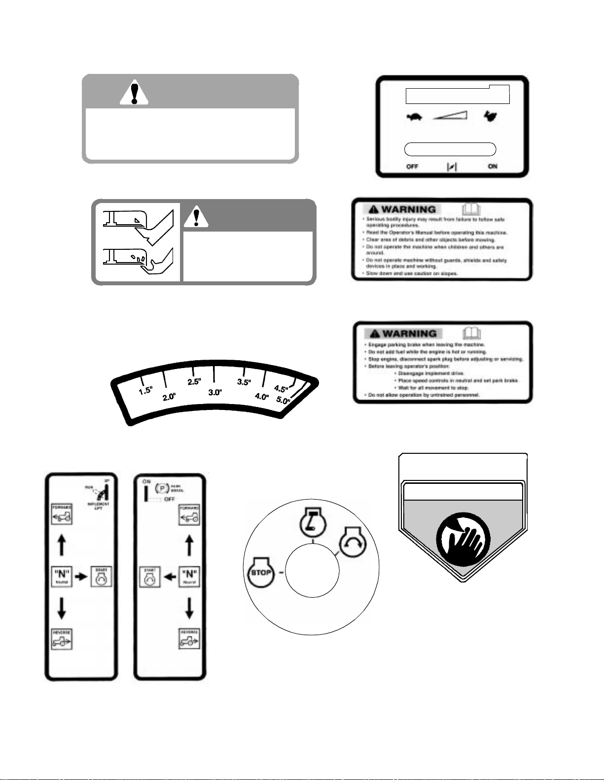
SAFETY DECALS AND LABELS
WARNING
SHIELD MISSING
DO NOT OPERATE
Part Number: 00030635
Part Number: 00030633
Part Number: 01003859
DANGER
ROTATING BLADE
Do not put hands or feet
under or into mower when
engine is running.
Part Number: 01003858
Part Number: 01003449
Part Number: 01003450
TO REDUCE THE RISK OF INJURY,
DO NOT OPERATE MOWER UNLESS
DISCHARGE C HU T E COVER OR G R AS S
CATCHER IS IN ITS PROPER PLACE.
Part Number: 01002166
Part Number: 01003451
DANGER
KEEP HANDS and FEET AWAY
Part Number: 01003857
Part Number: 01003452
6
Page 7

SPECIFICATIONS
Engine: 19HP Kawasaki, 20HP Honda, 24HP Honda, 23HP Kawasaki,
25HP Kawasaki, 27HP Kohler, 28HP Generac
Type: Vertical air cooled V-Twin
Air Cleaner: Paper Element
Lube System: Pressurized with oil filter
Starter: 12-volt electric
Traction Drive: Engine to two variable-speed hydraulic wheel motors on each
drive wheel
Hydraulic Tank: 10 quart capacity, One quart filter
Cutter Deck;Drive: 48", 54", 60", & 72” Belt Driven
Clutch: Electric
Deck Lift: Hand lever w/pin lock for height adjustment
Cutting Height: 1-1/2" to 5"
No. of Blades 3, belt-driven, power take-off from engine
Controls: Engine ignition and start switch; throttle; choke; left and right
steering le ver s; ele ctric blade clutch s witch; parki ng br ake; mo wer
deck lift
Parking Brake: Mechanical linkage attached to the brake handle
Front Caster Wheels: 13 x 6.50 x 6
Tire Pressure: 8-10 psi Rear, 20-25 psi front caster
Drive Wheels: 60" deck & 72” deck, 24x12 - 12
Frame: 2" Steel square tube and plate, all welded construction
Seat: Adjustable seat with armrests. 5" Adjustment
Fuel Tank: Two 6.5 gallon w/individual shutoff valves
Ground Speed: 0-10 + MPH forward. 0-4 MPH reverse
Instrumentation Hour meter, Tachometer, Maintenance-minder
Net Weight: 950 lbs w/48" deck, 980 lbs. w/54" deck, 1070 lbs. w/60" deck,
1330 lbs w/72” deck
7
Page 8
OPE RATIN G IN ST R U CT ION S
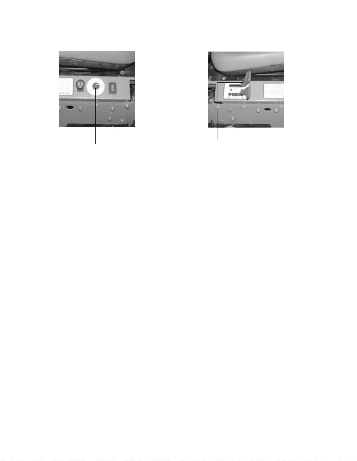
Figure. 1 Figure. 2
Electric Blade
Clutch Switch
Ignition Switch
Tach and
Hour Meter
A.General
1. When Mo wi n g:
a. Keep adults, children, and pets away from
the area to be mowed.
b. When operating this mower, in the forward
direction, do not allow the steering levers
to return to Neutral on their own. Always
maintain a firm grip on the levers , operate
them smoothly and avoid any sudden
movements of the lev ers when s tarting and
stopping.
c. If the mower is equipped for side dis-
charge, never use the mower without the
discharge chute installed and placed in the
down position.
d. Always remove debris and other objects
from the area to be mowed (Note: debris
and loose grass will reduce traction).
e. Mow only in daylight.
f. Wat ch f or holes, sprinkler heads, and other
hidden hazards.
g. Avoid driving too close to trees, creeks,
ditches, sand traps, and other obstacles.
h. Before backing up, check behind and
watch where you are going.
i. Always reduce speed when making a turn,
and when grass is wet.
j. Always mow across slopes, never up and
down the slope. Do not operate on steep
slopes and slow down before turning.
Avoid tur ning downhill if possible, start at
the bottom and work up to the top. Use
extra care and go slowly when turning
downhill.
k. Be careful when crossing gravel paths or
roadways. Always turn off the blade clutch
switch and wait until the blades stop rotat-
Engine throttle
Choke Lever
ing and raise the cutting deck to the transport position. Always allow other vehicles
to have the right of way.
l. If you hit a solid object while mowing, turn
off the blade clutch switch, place the steering levers in the neutral, opened-out position, move the throttle to slow, set the
parking brake, shut off the engine, and
take the key from the ignition switch.
Inspect for damage. Repair the damage.
Make sure the blades are in good condition
and that the blade bolts are tight before
restarting the engine.
m. Nev er leave t he mower unattended without
observing the following: turn off the blade
clutch switch, placing the steering levers i n
the neutral open-out position, moving the
throttle to slow, setting the parking brake,
shutting off the engine and taking the key
from the ignition switch.
n. Never walk or stand on the discharge side
of the mower when the engine is running.
Turn off the blade clutch switch if another
person approaches while you are operating the mower.
o. Never attempt to operate the traction unit
without having the mowing deck attached.
p. Keep the mower and especially the engine
and hydraulic components clean and free
of grease, grass, and leaves to reduce the
chance of fire and permit proper cooling.
2. Safety Awareness when Mowing
a. Do not operate on steep slopes, those
above 15 degrees (27% slope).
b. Avoid turning downhill if possible, if not use
extra care and go slowly.
8
Page 9

c. Avoid turning when going downhill, traction
is at a minimum going downhill.
d. Do not operate with discharge side of the
mowe r toward st reets, buildings, p l ay-
grounds, parking lots, other machines, ani-
mals, and other people.
e. Avoid operation or use extreme care if the
traction surface is wet, unstable, or slip-
pery.
f. Use extra care when grass clippings,
leaves, pine needles, or debris are present
as traction can be reduced.
g. Slow-down before turn ing and come to a
complete stop before any zero t urn maneu-
ver.
h. Do not stop machine or park machine over
combustible materials such as dry grass,
leaves, debris, etc.
3. To Mow Grass and Produce a Striped P attern
a. Pick a point on the opposite side of the
area to be mowed (post, tree, shrub, etc.).
b. If on an hillside, star t at the bottom so that
the turns are uphill rather than downhill.
c. Align the mower so as to head directly
toward the object on the far side.
d. Slowly increase the speed of the machine
to match cutting conditions, terrain, and
operator familiarity with the controls and
keep the machine headed directly toward
the alignment object. Do not go fast as to
reduce cut quality or to be uncomfortable
in controlling the speed and direction of the
machine.
e. When approaching the other end of a strip,
slow down or stop before turning. A U-turn
is recommended unless a zero turn is
required. The speed of a U-turn that will
allow for machine controllability and minimal turf defacement will be dependent on
several factors including: the speed of the
turn, the radius of the turn, the tire tread
pattern, the traction coefficient of the tire to
the traction surface, the slope of the traction surface.
f. Remem ber, a zero turn requires that the
forward or reverse travel of the machine be
stopped prior to the initiation of the turn or
severe turf defacement can occur.
g. To prevent rutting or grooving of the turf,
change the direction that the strips are
mowed by approximately 45 degrees the
next and each subsequent time that the
area is mowed.
B.Controls
Engine Ignition and Start Switch:
1.
ure 1.) Located on the instrument housing
below the rig ht side of the operator’s seat.
When the key is inserted and turned clockwise, 45 deg ree s, the ign itio n ci rcuit is cl osed.
Turning the switch fu rther aga in st spring pressure starts the engine. The engine will only
start if the blade clut ch switch is in th e “off”
position, the parking brake is engaged and
the left and right steeri ng lever s are in the
neutral, opened-out position. The ke y sh ould
always be re m oved from the swit ch if the
operator l eaves the m ower’s seat.
Engine Throttle Control:
2.
Located on th e left side of the mow er next to
the operat or’s seat. Mo ving th e thr ottle cont rol
from the rear to the front will increase the
engine spee d fr om slow to fast.
Left and Right Steering Levers:
3.
3.) These hinged le ve rs ope n out to the sid e in
the neutral position to permit the operator to
be seated or to leave the mower’s seat. The
operator, when seated, can pull the levers up
to the operating position, a comfortable forearm’s length away. These levers control all of
the movements of the mower. Pushing both
lev ers forward causes the mower to move forward. Pulling both lev ers bac k causes the
mower to move bac k ward. Pushing one lever
ahead of the ot her lever cau ses the traction
wheel on the side where the lever is ahe ad t o
rotate f aster than the other traction wheel,
making the mo we r tu rn tow ard t he side w here
the le ver is behind. When on e l ever is pushed
forward and the other l ever pulled back the
same amount, one traction wheel will turn in
reverse a nd the mower will turn within its own
length.
In order to start the engine, both steering
lev ers must be opened out to the side in the
neutral position; the parking brake must be
engaged; and the blad e clu tch s w itch m us t be
“off”. However, once the engine starts, the
parking bra k e must be release d before the
operator pl aces the steering levers in to the
operating position or the engine will
automatically shut off.
Note:
neutral when released, but they should be
placed in neutral b y the driver. If the Drive
Handles are not placed in neutral, the tractor
may creep.
(See Fig-
(See Figure 2.)
(See Fi gure
The Steering Le ver will return tow ard
9
Page 10

Steering Levers
Deck Lift Handle
Brake
Note: The 19hp
and 23hp use the 5
gallon fuel tank.
Figure. 3
Electric Blade Clutch Switch:
4.
(See Figur e
1.) Located on the right side of the mower
beside the i gnition swit ch . Thi s i s an “on/off”
push pull switch that controls the electric
blade c l ut ch which supplies po wer to the cutting b lades through the PT O. The switch must
be turned off to start the engi ne and should
be turned off for safety any time another person approaches the mower or the mowing
deck is raised to the tr ansport position. Power
to the electric clutch will also be cut off if the
opera to r leaves the operator’s seat.
Parking Br ake :
5.
(See Figure 3.) Located on
the left side of t he traction unit. Th e handle is
an ov ercenter le ver which ap pl i es the drumtype brake on each drive w heel when the handle is pulle d to the rear. The brake mus t be
engaged in order to start the engine.
Deck Lift Handle and Foot Pedal Lift
6.
Assist:
(See Figur e 3.) Located on the right
front corner of t he mowing deck . Raise the
mowing deck to the transport position, by pulling the lever to the rear and moving it inward
into the stop for transport. To lower the mowing dec k, pul l the deck lift handle and move it
outward. This lower’s the deck to the cutting
position .The foot pedal lift assist (n ot pictured
above) can provi de “li ft assist” to the ha nd
lever or with “foot effort only”. To provide
assistan ce to the lift handle: re m ove the
detent pin f rom t he pedal assembl y. Fold the
pedal down to the horizontal position so the
hole in the pe dal al i gns with the hole in the
lever. Re-install the det ent pin. Pull on the Li ft
handle an d de pres s the f oot p eda l to r ais e the
deck. Lifting with “foot effort only” depress the
foot pedal (the hand lev er will lock into transport position if f ully depres sed). To relea se the
lift mechanism depress the foot pedal, move
the hand l e v er out wa rd a nd slo w ly red uc e f oo t
pedal effort to lower the m echanism. To service the unit: Remove the detent pin from the
Figure. 4
Fuel Shutoff Valve
pedal assembly. Fold the pedal up to vertical
position so the hol e i n t he pedal aligns with
the hole in the lever. Reinstall the detent pin.
This is the requi red position for the foot pedal
for the foot platform to tilt forward and to
access some of the machines components.
Fuel Shutoff Valve:
7.
(See Figur e 4.) Located
on top of the fuel tank(s). When tu rned in a
clockwise direction until it stops, it will shut off
the flow of fue l to t he engine. When tu rned in
a counterclockwise direction it will open and
allow fuel to flow to the engine. Close thi s
valve if you are not going to run the mower for
a period of 30 minutes or more to pre vent
flooding the engine.
Seat Adjustment Lever:
8.
The Seat Adjustment Le ver is located beneath the seat. The
Seat Adjustment Lever is used to move the
seat fo rward and backward. To place the seat
in the desired position pull the seat adjustment lever to the left then push the seat forward or back to the desired position. Release
the lever so the seat will lock in place.
Digital Tachometer and Hour Meter:
9.
Figure 1) Located on the right side of the
mower in front of the igni tion s witch. When the
machine is running the tachometer displays
engine rpm. When the m achine is off the
tachometer displays running time.
Choke Lever:
10.
(See Figure 2) The Choke
Lever is located on the left instrumen t pa nel
next to the se at. The Chok e Lever is oper at ed
manually. Having t he Choke Lever in the ON
position h el ps the engine to start during initial
start-up. During normal operation the Choke
Lever should be in the OFF position.
Note:
each recommended lubrication int erval. There
is a flashing “OIL” at each recom m ended
engine oil and filter change.
There will be a flashing “LUBE” for
(See
10
Page 11

C.Initial Adjustments
1. Chec k th e fluid levels and ti res:
Note:
before starting the engine.
a.
b.
Note:
SAE 10W40 engine oil, rated for service SJ.
c.
d.
These checks should be made daily,
Fuel:
Using a good grade of unleaded,
regular gasoline (for a gasoline engine), fill
the fuel tank (beside the engine on the left
or right side of the mower). When the fuel
reaches one inch from the top of the tank,
stop. DO NOT OVERFILL. Space must be
left for expansion.
Engine Oil:
(Filled at the factory before
shipment.) Pull out the oil dipstick, wipe it
off and reinsert it. Pull it out again and read
the oil level. If it is below the operating
range, add oil through the fill tube using a
funnel to bring it up to the top of the operating range.
Gasoline Engine: Use SAE 10W30 or
Hydraulic Oil:
(Filled at the factor y before
shipment.) The hydraulic oil tank is located
beneath the operator’s seat. Always wipe
off the area around the oil tank fill neck
before checking the oil level to prevent dirt
from contaminating the oil. Remove the
cap and make sure the oil level is up to the
lowest hole on the oil tank fill neck. The top
hole is for venting. If the oil level is low, fill
with a good grade of SAE20W-50 oil.
Tires:
8-10 psi Rear, 20-25 psi Front
Caster Tires
the procedur es below to set the appropriate
angle to the mowing deck.
a. Park the mower on a flat paved surface,
engage the parking brake, shut off the
engine, remove the key from the ignition
switch, remove connection of the spark
plugs and using the transport lever, lower
the mowing deck into the cutting position.
b. Using a ruler, pencil and paper, measure
and note the distance from the paved surface to the bottom edge of the mowing
blade at the front and the back of the deck
on each side of the mower. (Four dimensions.)
Note:
should be 1/8"-1/4" below the rear edge of the
deck so that the blades are cutting grass in
only the front half of their circular path. This
decreases fricti on and reduces the drive
power required.
The front edge of the mowing deck
c. If the dimension at the front of the mowing
deck is 1/8"-1/4" lower than the dimension
at the rear of the deck on each side of the
mower, do not adjust. If not, you will need
to adjust the Deck Lift Spring Assist (See
Figure 5). You may also need to adjust the
Deck Links (See Figure 5).
Deck Lift Spring inner nut
Note:
properly seat the bead to the rim. The normal
working pressure for the traction tires is 8-10
psi. The front caster wheels should be i nflated
to 20-25 psi.
New tires are overinflated in order to
2. Check that all Nuts, Bo l ts and Screws ar e
Tight.
3. Check the tension of the deck drive b elts.
a. Remove the deck cover
b. The tension of the deck drive belts are
maintained by a spring mechanism that
adjusts for wear and stretch.
c. Examine the belts for cuts, fraying, and
excessive wear. Replace if any of these
are detected.
d. Replace the deck cover.
Adjust the Mowing Deck:
4.
The cutting height
is set any where in the range of 1- 1/2" to 5".
You may need to adjust the mowing deck to
achie ve the prop er angle for mowing. Fol l ow
11
Figure. 5
Deck Li nks
d. Lower the mower deck to the cutting posi-
tion. With a wrench loosen the inner rear
nut on the Deck Lift Spring Assist. To
adjust the deck up or down, use a wrench
and with a few turns, adjust clockwise or
counter clockwise the outer rear nut of the
Deck Lift Spring Assist. Repeat this procedure on the opposite side of the Mower.
Once the deck is adjusted, retighten bolts.
e. With the deck still in the cutting position,
adjust the Deck Links. With a wrench
loosen the top inner bolt of the Deck Link.
To adjust the side of the deck up or down
turn the top bolt clockwise or counter
Page 12

clockwise a few turns. Adjust both front
and rear Deck links as necessary.
Retighten nuts.
f. Raise the mowing deck to the transport
position using the transport lever.
g. Use the transport lever to lower the mow-
ing deck to the cutting position and repeat
step “b.” above to make sure that the
desired cutting height has been attained. If
the dimensions are not correct, repeat
steps “c.” through “f.” abov e.
5. Lubricate all fittings li sted in the maintenance section.
D. Zero Turn Break-In And Operating
Procedures
DANGER:
Reread the “When Mowing” Safety Precautions.
The following procedures are suggested for operators of ride-on machines which have zero turn
capabilities.
1. Orientation:
a. Read the entire Operator’s Manual.
b. Sit on the machine, adjust the seat before-
and-after, then adjust the speed/directional
(lap bar) controls (they can be adjusted
before-and-after , as well as up-and-down
— 9/16" wrench required).
c. Become familiar w it h all o f th e ma ch ine
controls, instrumentation, safety and
instruction signs, and safety devices.
d. Move (or have moved) the machine to a
safe, level area with no obstructions including objects, pedestrians, and animals.
2. Initia l Ope rat ion :
a. Use protective equipment for eyes, hands,
hearing, feet, legs, head and other areas of
the body if needed — safety eye glasses,
gloves, earplugs, boots, hats, etc.
W ARNING:
Hearing Protection is required for all operator
exposure exceeding two (2) hours.
b. Ensure that the area is free of animals and
bystanders, especially children!
c. Survey the area where the equipment is to
be used to make sure it is free of debris,
sticks, stones, wires, bones, and other foreign objects which could cause injury to
bystanders, damage to the machine, or
damage to nearby facilities.
d. Inspect the machine to make sure:
1. All guards, shields (including mower
chute deflector) are in their proper place,
are secure, and are functional.
2. That there are no spilled or leaking fuel
or oil sources, nor loose fuel or hydraul ic
tank caps, hoses or fittings.
3. That there are no loose or missing hardware nor any missing items.
4. That no non-approved devices are
installed.
5. That all safety signs and decals are
properly installed and legible.
e. This is a one person mac hine, operator
only! Riders are not permitted under any
circumstance!
f. To start the engine on the machine:
1. Make sure the park brake is set to the
“ON” position, both lap bars are in the
neutral/start (opened-out) position, and
the Power Take Off (PTO also referred to
as blade control switch) is in the “off”
(down) position.
2. Move the choke control forward and the
engine speed control (throttle) forward
(half way).
3. Inser t the ignition key, turn the switch
toward the spring-loaded “Start” position,
maintain the Start position until the
engine begins to run, then release the
switch (it will return to the “Run” position).
4. Retard the choke slowly by moving it
rearward. If the engine is “cold”, the
choke may need to be partially applied
for a few minutes. Be sure to totally
retard the choke after the engine has
“warmed up”.
g. Check safety devices:
1. With the park brake engaged, move one
of the lap bars (speed/directional control)
from the neutral/start position to the neutral position (out of the slot, toward the
center of the machine) — the engine
should stop running. Move the lap bars
back to the neutral/start position and the
engine should run.
2. Repeat this procedure with the opposite
side lap bars.
3. With the park brake engaged and the lap
bars in the neutral/start position,
advance the engine speed control completely forward (Hi-idle), engage the PTO
control switch (pull upward), then lift off
the seat — the engine should stop running. Sit down and the engine should
12
Page 13

run. Turn off the PTO by pushing the
control switch down.
h. To dri ve in the FORWARD direction:
1. Set the engine speed to 2000 to 2500
rpm (refer to tachometer on right control
panel). This must be increased to full
speed (3525-3675 rpm) after becoming
familiar wit h the machine.
2. Release the park brake.
3. Move both lap bars out of the neutral/
star t position to the neutral position
(toward center of machine). Slowly, move
both lap bars toward the front of the
machine until the machine begins to
move forward — release the lap bars
and the machine should stop. The more
that the lap bars are moved toward the
front of the machine, the faster the
machine will move in the forward direction. Release the lap bars and the
machine should stop traveling f orward.
(This is a safety check, the normal procedure is for the operator to slowly bring
the lap bars to the neutral position).
4. Do not advance the lap bars rapidly as
this could cause turf defacement, loss of
traction, and/or instability.
5. To turn, advance one lap bar ahead of
the other and the machine will turn
toward the opposite from the side that
was advance d — I.E. to turn clockwise
(to the Right), move the LEFT lap bar f orward more than the right side, and to
turn counter-clockwise (to the LEFT),
move the RIGHT lap bar forward more
than the left side. NOTE: If one lap bar is
in the neutral position and the other is
advanced, the turn side tire will not
rotate and a “pivot turn” will be executed
— turf defacement could occur (if on
grass) as well as potential damages to
the traction surface and the tire. If the lap
bar on the turn side is not brought all the
way to neutral, then the turn side tire will
continue to rotate and a “U-turn” will be
executed with a low potential for turf
defacement as well as traction surface
and tire damage.
i. To drive in the REVERSE direction:
1. Make sure no bystanders, animals, or
objects are behind the machine. Look
behind the machine, and use extreme
care.
2. Slowly, move both lap bars toward the
rear of the machine until the machine
begins to move rearward. Release the
lap bars and the machine should stop.
The more the lap bars are moved toward
the rear of the machine, the faster the
machine will move in the reverse direction. Release the lap bars and the
machine should stop traveling in rev e rs e
(this is a safety check, the normal procedure is for the operator to slowly bring
the lap bars to the neutral position).
3. Do not retard the lap bars rapidly as this
could cause turf defacement and/or loss
of traction.
4. To tur n, retard one lap bar ahead of the
other and the machine will turn toward
the same side that was retarded — I.E.,
to turn counter-clockwise (to the LEFT),
move the LEFT lap bar rearward more
than the right side, and to turn clockwise
(to the RIGHT), move the RIGHT lap bar
rearward more than the left side. NOTE:
If one lap bar is in the neutral position
and the other is retarded, the turn side
tire will not rotate and a “pivot turn” will
be executed. Turf defacement could
occur (if on grass) as well as potential
damages to the traction surface and the
tire. If the lap bar on the turn side is not
brought all the way to neutral, then the
turn side tire will continue to rotate and a
“U-turn” will be executed with a low
potential for turf defacement as well as
traction surface and tire damage.
j. T o perform a “zero turn”:
1. Please note, a zero turn maneuver can
not be executed while the machine is
moving in the Forward or, Reverse directions, the machine must come to a stop
first.
2. To turn clockwise, slowly move the LEFT
lap bar forward while simultaneously
moving the RIGHT lap bar rearward.
Release both lap bars and the machine
should stop turning.
3. To turn counter-clockwise, slowly move
the RIGHT lap bar forward while simultaneously moving the LEFT lap bar rearward. Release both lap bars and the
machine should stop turning (this is a
safety check, the normal procedure is for
the operator to slowly bring the lap bars
to the neutral position).
3. Start the Engine:
a. Open the fuel shutoff valve.
b. Sit on the Seat. Set the parking brake
“On”.
c. M ove the left and right steering levers to
the neutral, opened-out position.
d. Turn the electric blade clutch switch “Off”.
13
Page 14

e. Push the throttle control to a position a
third of the way between slow and fast.
f. Insert the key in the ignition and start
switc h and turn the switch to “On”.
g. Gasoline Engine: If the engine is cold,
push the choke to the on position.
h. Turn the ignition key in a clockwise direc-
tion to the “Start” position until the engine
starts.
Note:
position for more than 10 seconds o r you may
damage the starter. If the engine d oes not st art
in this time, wait about 30 seconds and try
again.
i. Gasoline Engine: Once the engine starts,
Operatin g the Mower :
4.
ing-ra di us mower is not like operating a tractor-typ e riding mo wer . The z ero-turning -rad ius
mower is much more maneuverable and
much les s fatiguing to operate. Ho weve r, getting use d to the fingertip control of the zeroturning-radi us mower ta kes some prac t i ce.
We strongly recommend that you locate a
“test area” where you can operate the mower
for about 30 minutes without being disturbed.
a. Get into the operator’s seat.
b. Start the engine.
c. Use the transport lever to r aise the mowing
d. After the engine has warmed, adjust the
e. Release the parking brake.
f. Fold in the steering levers to the operating
Do not hold the key in the “Start”
push the choke on halfway and as the
engine warms, push the choke off all the
way.
Operating a zero-turn-
deck to the transport position. Make sure
the blade clutch switch is off.
throttle to the fast position.
position.
levers backward the faster the mower w ill
go backward.
i. To turn, pull the lever back on the side to
which you want to turn. The farther back
you pull the lever, the faster and more
sharply you will turn. Initially, you will have
to be careful to avoid tur ning to fast and
too far.
j. After you have mastered operating the
mower, use the transport lev er to lower the
mowing deck to the cutting position and
pull on the electric blade clutch switch to
start the blades rotating.
k. Practice mowing in straight passes. When
you feel confident, slowly practice mowing
around obstacles such as trees.
5. Parking the Mower:
a. Push off the electric blade clutch switch.
b. Use the Deck Lift Handle to raise the mow-
ing deck to the transport position.
c. Dr ive the mower to the cleanup or storage
area.
d. Move the throttle to slow.
e. Place the steering levers in the neutral
position.
f. Set the parking brake.
g. Turn off the ignition switch and take the key
from the switch.
h. Close the fuel shutoff valves.
MAINTENANCE AND
SERVICE
WARNING:
Disconnect the spark plug wires or remove the
key from the ignition to prevent the engine
from accidentally starting before performing
any maintenance on this mower.
WARNING:
When operating this mower forward, do not
allow th e steerin g levers to return to the ne utral position on their own. Always maintain a
firm grip on the steering levers, operate them
smoothly and avoid any sudden movements of
the levers when starting or stopping.
g. To go forward, move both steering levers
slightly forward and the mower will slowly
move forward. The farther you move the
levers forward the faster the mower will go
forward.
h. To back up, move both steering levers
slightly backward and the mower will slowly
move backward. The farther you move the
A. Mower Deck
1. Removing th e Mower Deck:
a. Apply the parking brake. Remove ignition
key and both spark plug caps.
b. Lower the cutter deck to the ground. Cap-
ture the lift handle by placing the height of
cut clevis pin above the lift handle.
c. Remove tension of the PTO belt by moving
the belt tensioning rod.
Note:
tension due to the weight of the deck. When
removing t he lift linkage from the deck the tension of the springs will go from the deck to the
lift handle. Not capturing the lift handle while
removing the lif t linkage from the deck will
cause it to snap back.
14
There is a certain amount of spring
Page 15

Figure. 6
Linch Pins
Linch Pins
Height of Cut Clevis Pin
d. Detach the mower drive belt.
e. Remove six linchpins (See Fig. 6) (4) from
the deck and (2) from the front of the
mower. Remove the linchpins on the left
and right rear side of the cutter deck (2);
remove the linchpins on the left and right
front side of the cutter deck (2); and
remove the linchpins on the front of the
mowe r (2).
f. Turn front caster wheels outward.
g. Shift the deck toward the ignition switch
side of the mower and remove.
h. To install reverse the process.
2. Changing a Blade:
a. Remove the Key from the ignition and dis-
connect the spark plug.
b. Jack up the front of the mowing deck about
one foot and block it in that position.
c. W rap a rag around one end of the blade
and grasp it to prevent it from turning, or
secure the blade by placing a block of
wood between the blade and the deck
housing.
d. Use a 1-1/8" socket wrench on the pulley
side of the spindle to secure.
e. Remove the hex nut using a 1-1/8" wrench.
f. Remove the hex nut.
g. To replace the blade reverse the above
process and tighten nut to 100-120 lb ft.
WARNING:
Never mow with dull blades! Blades that are
bent should be replaced! The cutting blades
are sharp and can cause severe injury. Wrap
the cutting surface of the blade with a rag to
avoid injury.
a. Set the parking brake.
b. Clean any debris from the blades. Keep
blades sharp and free of build up at all
times.
c. Sharpen blades evenly at the original 30°
angle to maintain balanced cutting blades.
Do not sharpen the underside of the
blades. Use a electric blade sharpener, a
conventional electric grinder or a hand file
to sharpen the blades.
d. Replace any blade with severe nicks or
dents that cannot be removed by filing.
e. Check the balance of the blade after
sharpening by placing it on a blade balancer. Do not use un-balanced blades.
f. If the blade dips on one end, file stock off
of the cutting surface on that end.
Note:
anced—REPLACE.
Blades that cannot be easily bal-
3. Changing the Blade Drive Bel ts:
a. Set the parking brake. Remove ignition ke y
and both spark plug caps.
b. Unscrew the wing nuts from the deck cov-
ers and remove both covers.
c. Using a 1/2" socket breaker bar or socket
rachet insert the male end into the 1/2"
opening in the lower idler arm assembly
and pull the idler arm clockwise. While
holding the idler arm back, loosen the
blade drive belt from the pulley and slide
the belt away from the pulley.
d. Remove tension of the PTO belt by moving
the belt tensioning rod. Loosen the belt
retaining bolt.
15
Page 16

Cover
Plate
Spindle
Figure. 7
e. Pull the tensioner pulley away from the belt
and remove the PTO belt then remove the
blade drive belt.
f. Reverse the process to install the belt.
Note:
tighten. Adjus t the idler pulley so that a tenpound pull with a spring scale between two
pulleys defl ects the belt about 1/2".
When replacing belts do not over-
4. Changing the Spindle Assembly
a. Jack up the front of the mowing deck about
one foot and block it in that position.
b. Make sure the blade clutch is disengaged.
c. Remove the deck cover.
d. Remove the drive belts. (See 3. Changing
Blade Drive Belts.)
e. Remove the cutter blade. (See 2. Chang-
ing a Blade.)
f. Using a wrench or socket rachet remove
four hex nuts, and the four hex head cap
screws. Remove the spindle assembly.
B.Hydraulic Oil
WARNING:
Never overf ill t he hydr aulic units. Damage c an
occur if the oil level is not within the proper
operating range.
Note:
small quantiti es and recheck the oil level
before ad ding more. It i s im portant th at y ou do
not overfill the reservoir.
hen adding hydraulic oil, do so in
W
Figure. 8
1. Adding Hydraulic Oil
Hydraulic Tank
(use SAE20W 50)
a. Place the Mower on a level surface and
engage the parking brake.
b. Stop the engine and remove the key
from the igniti on sw itch.
c. Clean the area around the Hydraulic Oil fill
neck.
d. Remove the hydraulic fill cap and check
the level. The correct level is up to the lowest hole of the oil tank fill neck.
e. Pour hydraulic oil into the reservoir up to
the lowest hole in t h e o il tank fill neck, if
necessary.
2. Draining Hydraulic Oil
Used hydraulic oil must be disposed of properly. Do not
pour it down a drain or sewer, or du mp it on op en land , th is
creates an environmental hazard . Please be aware o f the
environment when disposing of used oil.
a. Place the Mower on a level surface and
engage the parking brake.
b. Stop the engi ne and remove the key from
the ignition switch.
c. Rem ove the mower deck. See section on
Mower Deck.
d. Raise the seat forward to expose the
hydraulic oil fill point.
e. Clean the area around the hydraulic fill oil
cap.
f. Remove hydraulic fi ll o il c ap.
g. Place a suitable container (at least 2 gal-
lon) under the hydraulic reser voir and filter.
h. Remove the hydraulic filter to allow hydrau-
lic oil to drain. Remove the drain plug from
the bottom of the hydraulic oil tank to drain.
Replace the plug.
i. Place a small pan under the pump motor
frame. Remove fill oil cap from hydraulic
reservoir for faster drainage. Remove nut
16
Page 17

caps and drain oil from both left and right
pumps. Replace and retighten nuts.
Hydraulic pumps
c. Store the battery with a full charge. A dis-
charged battery will freeze (refer to the
table below).
Specific Gravity Freezing Temp (°F)
1.265 -71
1.250 -62
1.200 -16
Figure. 9
Unfasten hos e and dra in from
this side of both pumps.
j. Coat new filter seal with oil before installa-
tion. Install new hydraulic oil filter filled with
new oil.
k. Add proper amount of hydraulic oil to res-
ervoir.
l. Run and purge gearboxes. Check oil level.
m. Add proper amount of hydraulic oil to res-
ervoir and repeat step L.
C.Electrical Circuit
Danger:
Read General Safety Precautions Nos. 9 and 10.
Battery:
1.
operator’s seat. Remove the fillcaps and
check the level of th e l iq uid el ectrolyte in the
battery ev ery 50 oper ating hours. If the le v el in
any of th e six cell s has dropped belo w the
bottom of the split ring inside t he f ill ho le , re fill
the cell with distilled water. To keep the outside of the battery clean, brush on a strong
solution of bica rbona te of soda an d w ater and
rinse with clean water. Keep the contacts and
cable en d s c l ea n with a wir e brus h an d make
sure the c onnections are t i ght . Coat the terminals with petroleum jelly to prevent corrosion.
Battery Stora ge:
2.
long periods of t i m e th e following guidelines
should be taken.
a. Disconnect the battery cables from the ter-
b. Clean the battery before storing. A dirty
The battery is located beneath the
When st oring the Mo w er for
minals and remove the battery. You will
have to remov e the control panel to access
the battery strap. Replace control panel.
battery will lose its charge over time.
1.150 5
1.100 16
d. Re charge batter y when ever the specific
gravity value is less than 1.225
3. B atter y Removal
Warning:
When removing the cables from the battery
follow these steps to avoid a short between
the wrench and the frame.
a. Remove the Negative (black) cable.
b. Remove the Positive (red) cable.
c. Release the hold down straps.
d. Remove the battery without tipping.
4. Installing the Battery
Note:
tory fully charged and filled with electrolyte.
a. Attach the Positive (red) cable.
b. Attach the Negative (black) cable.
c. Attach the rubber battery strap.
5. Jump Starting
The battery is delivered from the fac-
Warning:
Failure to use this starting procedure can
cause sparking, and the gases in the battery
to explode.
a. At tach the end of the red jumper cable to
the Positive terminal (+) of the charged
battery.
b. At tach the other end of the red jumper
cable to the Positiv e terminal (+) of the low
charge bat t ery.
c. Attach the end of the black jumper cable to
the Negative terminal of the charged battery.
d. At tach the other end of the black jumper
cable to the frame of the unit with the low
charge bat t ery.
Fuses:
6.
between th e i gnition and start switch and
There is one f use lo ca ted in t he wi ring
17
Page 18

other elect r i cal co m po nents. This is a standard plug-in type au tomotive f use rated at 7. 5
amp.
Safety Switches:
7.
There are five safety
swi tc hes in the electrica l circuit which control
the engin e. They are (1) th e blade clutch
swi tc h, (2) the parking brake sw itc h, (3) the
left and (4) the right steering lever switches
and (5) the seat switch.They operate so that
in order to start the engine, the blade clutch
swi tch must be off, the parking brake must be
engaged , and both steering levers must be
opened- out to the side in the neut ral position.
Once the engine is started, the seat mu st be
occupied and the parking brake must be
released before either of the steering levers is
folded up to the operating position or the
engine’s electronic ignition will be grounded
out and the engine will stop. Also, the seat
must be occ upied befor e the blade clutch
swi tch can cause the blades to rotate.
Safety Switch Operation Checks:
8.
lowing operational ch ecks should be made
daily.
Blade Clutch Switch:
a.
Sit in the operator’s
seat. With both steering lev ers opened-out
in the neutral position and the parking
brake engaged, turn the blade clutch
switch “on” and try to start the engine. The
engine should not start. If it does, the blade
clutch switch must be replaced. If the
engine does not start, turn the blade clutch
switch “off” and start the engine. Now turn
the blade clutch switch “on” and the blades
should rotate. If the blades do not turn, the
blade clutch switch must be replaced, the
seat switch must be replaced or the electric PTO clutch must be repaired. The airgap should be checked every 300 hrs. (or
less, if severe operating conditions exist
such as when there are many on/off
cycles, mulching operations, material collection systems used, and dusty/dirty conditions), and the air-gap adjusted if more
than 0.035". To inspect, remove the “negative” cable from the batter y and all sparkplug wires. The air-gap should be checked
with feeler gages in the three slots of the
BBC. The air-gap should be adjusted to
0.013" to 0.015". There are three inspection slots i the brake cover. To adjust, successively tighten each of the three gap
adjustment nuts an equal amount. Insert a
feeler gage (0.013" to 0.015") into each
slot as the air gap adjustment nut are tightened. The correct adjustment occurs when
slight contact with the feeler gage occurs.
The fol-
Engage the BBC a couple of times, and recheck the air-gap. If it is not between
0.013" and 0.015", repeat the adjustment
procedure.
Parking Brake Switch:
b.
Sit in the operator’s seat. With both steering levers
opened-out in the neutral position and the
blade clutch switch “off”, release the parking brake and try to start the engine. The
engine should not start. If it does, the parking brake switch must be repositioned or
perhaps replaced. If the engine does not
start, engage the parking brake and start
the engine. Swing one steering lever up to
the operating position and the engine
should stop. If the engine does not stop,
the parking brake switch must be repositioned or replaced.
Left and Right Steering Lever Switches:
c.
Sit in the operator’s seat. With both steering levers opened-out in the neutral position, the parking brake engaged and the
blade clutch switch “off”, swing the left
steering lever up to the operating position
and try to star t the engine. The engine
should not start. If it does, the left steering
lever switch must be repositioned or perhaps replaced. Open the left steering lever
to the neutral position and swing the right
steering lever up to the operating position
and try to star t the engine. The engine
should not start. If it does, the right steering lever switch must be repositioned or
perhaps replaced. If the engine does not
star t, Open the right steer ing lever to the
neutral position and start the engine.
Swing the left steering lev er up to the operating position and the engine should stop.
If the engine does not stop, the left steering
lever switch must be repositioned or
replaced. Open the left steering lever out to
the neutral position and start the engine.
Swing the right steering lev e r up to the
operating position and the engine should
stop. If the engine does not stop, the right
steering lever switch must be repositioned
or replaced.
Seat Switch:
d.
With both steering levers
opened-out to the neutral position, the
parking brake engaged and the blade
clutch switch in the “off” position, start the
engine. Now release the parking brake,
hold down on the back of the operator’s
seat against spring pressure, and swing
one of the steering levers up to the operating position. Release the operator’s seat
and the engine should stop. If the engine
18
Page 19

does not stop, the seat switch must be
replaced. With both steering levers folded
out in the neutral position, the parking
brake engaged and the blade clutch switch
in the “off” position, sit in the operator’s
seat and start the engine. Turn the blade
clutch switch to the “on” position and the
blades should start to rotate. Raise up
slightly off the operator’s seat and the
blades should stop. If the blades do not
stop when you dismount from the operator’s seat, the seat switch must be
replaced.
Electric PTO Clutch:
e.
when the engine is running, the operator is
in the operator’s seat and the blade clutch
switch is turned on.This electric clutch is a
fairly trouble free device. If a problem
develops and the blades do not turn, first
check the 7.5 amp fuse in the yellow, 16gauge wire between terminal “L” (for the
Gasoline Engine) on the ignition switch
and the hour meter and then investigate
the wiring harness and the connections to
the seat switch, the blade clutch switch and
the electric blade clutch. Then check out
the seat switch, the blade clutch switch and
finally the electric blade clutch.
This clutch operates
D.Tires
The two front wheels are caster wheels that are free
to swivel to accommodate the direction of the Mower.
The two rear wheels are used to propel the Mower in
the direction of input from the drive handles. Inflation
pressure of the rear tires is important for stability
while the Mower is in operation. If the tire diameter is
not equal between the two tires, the Mower will pull to
one side .
Inflation Pressure:
1.
a. Traction Tires—20 psi max; 8-10 psi rec-
ommended
b. Front Caster Wheel—28 psi max; 20-25
psi recommended
c. Cutting Deck Ball Wheels—Solid Polyure-
thane.
Use the Following guidelines for maintaining the tires:
a. Balance inflation pressure between the
rear tires to help maintain straight travel
(see tire side wall for proper inflation pressure).
b. Keep the valve caps tightened to prevent
air pressure loss.
Leaking Ti res:
2.
or replace imme diately. The normal procedure
is to remove the wheel and r epl ace it with a
spare. Take the leaking tire to a maint enance
area and repair. If a tire is getting soft, park
the mo wer on the nearest level, paved area. If
the leaking tire is on a traction wheel, put
bloc ks on each side of the oppos ite traction
wheel and jack up the tire that leaks about an
inch off the g round. Loosen and remove the
lug nuts and remove the wheel. Mount a
spare whe el and tire , rep lace the lug nuts , and
using a torque wrench, tighten the m to 60
10 ft-lbs.
If the leaking tire is on a front caster wheel,
block both traction wheels and raise the
caste r whee l s o that t he tir e is a n i nc h of f t he
ground. Loosen and remove the locknut from
the axle assembly and pull the axle assembly
from the caster yoke. The wheel and two
spacer sleeves will drop free. Slip the axle
assembly through one side of the caster
yoke, through a spacer sleev e, a spare wheel,
the other spacer sleeve and finally through
the other side of the caster yoke. Then
tighten the locknut on the end of the axle
assembly.
Lower the mower off the jack and continue
mowing. The wheel with the leaking tire
should be taken to the maintenance area, the
tire inflated to 20 psi and the wheel placed in
a large bucket of water. Carefully inspect the
tire, rim and valve for escaping air bubbles
whic h indicat e a leak. Mar k each leak with a
yellow marking crayon and then deflate the
tire to 8 psi and repeat the inspection. If the
leaks you find are pin hole size to 1/16"
diameter, the tire can be repaired using an
aerosol can of tire inflater and latex sealer
available from any auto supply store. Follow
the directions on the can. If the leaks are
larger than 1/16" diameter, the tire can be
repa ired wit h r ubbe r pl ugs also availabl e in a
kit from any auto supply store. If the tire bead
is damaged, a tube will have to be installed in
the tire or the tire will have to be replaced.
Creeping:
3.
backward movement of the mo wer when the
throttle is on and the lapbars are in the
opened-ou t position. If y our mower cr eeps do
the following.
a. Jack up rear of unit.
b. Place Lapbars in neutral opened-out posi-
tion.
c. Locate jam nuts. (Reference control
assembly in pa rts list ) .
When a flat tire occurs, repair
Creeping is the slight forward or
±
19
Page 20

d. Loosen jam nuts on both ends of rod con-
nectors. See Control Assembly in the Illus-
trated Parts Book (ONLY if mower creeps.)
e. Start unit and push throttle all the way on.
f. If unit creeps forward rotate rear rod con-
nectors counter-clockwise. And if unit
creeps in reverse, rotate clockwise.
pin from the clevis pin and pulling the clevis pin from
the brake clevis. Loosen the hex nut and turn the
brake clevis in a clockwise direction one full turn
looking down the brake rod. This will tighten the brake
about .040 inch. Tighten the hex nut and reassemble
the brak e clevis to the brake shaft assembly. Normally,
both brak es should be adjusted and equal amount.
Adjust the appropriate rod connector. The
left rod for the left side of the mower and
the right rod for the right side of mower.
Afterward, retighten jam nuts.
E. Brakes
While the mower is in motion, all braking is performed
dynamically through the hydraulic pumps and traction
motors, controlled by the two steering levers. When the
mower is parked with the engine shut off, the hydraulic
system l oc ks th e trac tion whee ls .
Note:
reverse by pushing, you must release the
dynamic braki ng. Locate the valves on the
pump. Turn valves counter-cl ockwise one
quarter turn to push the unit. After pushing
the mower to t he desired location, retu rn both
valves to the oper ati ng position (See photo
below)
To move the mower forward or in
.
Repair:
2.
The mower is equipped with internal
wet drum brakes a nd will not n ormally require
maintenanc e. If they are not working pr operly,
please contact your service center.
F. Hydraulic System
Hoses:
1.
oil tank to the oil fil t er to the hydr aul ic lines
daily f or l eaks or abrasi on and replace any
damaged hos es. Make certain there are no
kinks or twists in any hose.
Hydraulic Oil Tank and Filter:
2.
Note:
filter after the first 50 hours of operation and
every 500 hours thereafter .
To drain the hydraulic oil tank, place a 2 gallon drain
pan under the drain plug on the bottom of the
hydraulic oil tank. Remove the drain plug, drain the
tank, then replace the plug. Place the drain pan under
the filter and remove the filter by unscrewing in a
counterclockwise direction. The filter will be full of oil,
so empty it into the drain pan. You don’t have to drain
the rest of the hydraulic system. Fill the replacement
filter with a good grade of 20W-50 oil and lubricate the
sealing surface. Screw the filter onto the filter base
until it seats an d then another one-half turn to seal.
Check the hoses from the hy draulic
Change the hydraulic oil and the oi l
Hydro Release Valve
When the mower is parked with the engine running
and the steering levers opened out in the neutral
position, the parking brakes should be applied. The
parking brakes are drum-type brakes mounted on
each traction wheel.They are both engaged by the
same operating lever.
Adjustments:
1.
The parking b rake handle is an
overcenter lever that should engage with
moderate force.
Note:
tighten the brake rods going back to the brake
arms equally. Tighten rods one full turn and
check parking capacity. Repeat Step.
To increase parking brake capacity
To adjust either brake individually, disconnect the
brake rod from the brake arm by removing the cotter
Note:
cap and the area around it before remo ving the
cap to prevent dirt from contaminating the oil.
Always wipe off the hydraulic tank fill
Remove the fill cap and fill the tank with the same
20W-50 oil selected for the filter until the oil level is up
to the level of the second hole in the fill tube. Leave
this air space for expansion. Start the engine and let it
run at idle for about five minutes. Check the filter for
leaks. Idling the engine and the pumps in this way will
purge any air from the system. Shut off the engine
and recheck the oil level in the tank. Top-off if
necessary until the oil level is up to the second hole in
the fill tube.
Note:
ture, turn off engine and re-check hydraulic
oil. If oil appear s foamy or contains excessive
air bubbles, DO NO T OPERATE UNIT. Cont act
service technici an.
After unit is up to operating t empera-
20
Page 21

Hydrostatic Pum ps and Motors:
3.
are the hardest-working co m ponents in the
hydr au lic sy stem. T he y ar e i n oper a tion a ll t he
time the en gine is running. Because of
ex tr em ely close tolera nces, wear i s an important factor in their life.
hydraulic oil an d
harm to the pum ps. Ca vitat ion is a b loc kage in
the supply li nes that produces a partial vacuum causi ng violent bubbling in the hydraulic
oil in the pum p.
Check the two suction hos es (the hoses connected to the filter) daily before starting the
engine. Look for a flatt ened condition or an y
leaks and repair or replace as necessary. A
flattened or leakng suction hose will permit
cavitation t o develop which can de stroy the
pumps in a sh ort time.
Contaminants or foreign matter in the oil will
also damage the pumps . To prevent t hi s, use
a filter that ca ptures particles as small as 30
microns or 30 millionths of a meter in diameter. You can help in the batt l e against dirt by
being very careful when you remove or repair
a component in the hydraulic system. Thoroughly cle an of f any componen t before you
work on it. Plug the ends of any hose or line
you rem ove with a rubber or plastic plug. Use
plastic caps to seal off the ends of hydraulic
fittings . Place an y compon ent you remov e in a
clean plastic bag so it can’t pick up dust or
dirt. Clean your hands frequently when working on the hydraulic components.
Note:
If a pump fails, contact y our Cub Cadet Commercial dealer. Do not disass emb le the pump.
Steering Lever Adjust ments :
4.
mower on level ground with t he engine running, parki ng brake off and s teering levers
opened ou t to the neutral position. If the
Mower begins to creep, adjust the S teering
Levers.
If the mo w er c re eps , firs t de termine wh ether it
creeps to the righ t or left side and which direction the mower moves — to the front or the
rear. To make the adjustment, place th e st eering levers in the opened-out neutral position
and set th e park i ng brake , s hut off the engine,
take t he key from t he ignition switch and pivot
the seat forward. If the mower creeps to the
right, you will adjust the linkage on the left
side of the mower and vice-versa. Remove
the cap screw and lock washer th at secure
the linkage control arm rod end bearing to the
control lever pivot. Loosen the jam nut which
The pumps are not owner-repairable.
Contaminants
cavitation
The pumps
does the greatest
Place the
in the
prevents the rod end bearing from turning . I f
the mower cr eeps f or war d, thre ad the r od en d
bearing one-ha l f t urn clockwise into the l in kage control arm. If th e m ower creeps backward, t hread the ro d e nd be aring one hal f t urn
counterclockwise out of the linkage control
arm. Then tighten th e j am nut and reconnect
the rod end beari ng to the control lever pivot
by replacing the cap screw and lock washer.
After adju st ing the steering l inkage, swing the
seat bac k t o i t s normal position and place the
steering lever on the side you adjusted up to
the operat ing positio n. If y ou f e el a sl ight p ush
forw ard or a sli ght pu ll bac kw a rd fro m the neutral positi on you must ad j us t t he l ever re turn
assembly . To do this, swing the steering lever
back out to the neutral position, pivot the seat
forward and loosen the jam nut on the lever
retu rn rod where it i s threaded into the hexshaped end of the l ever return bolt. If the
steering lever was pushed forward, turn the
hex-shaped lever return bolt clo ckwise onehalf turn off of the lever return rod. If the steering lev er wa s pulled b ac k, turn the he x shape d
lev er return bolt counterclockwise one-half
turn onto the le ver return ro d. Then tigh ten the
jam nut, pivot the se at back into the operating
position and st art the mo wer to check tha t
your adj us tments were made cor rectly.
G. Storage
General:
1.
for a few months, it should be st ored in a dry
location that is not subject to dra st ic c hanges
in temperature. Before storing, the following
maintenanc e procedures should be performed.
a. Clean the mower. The entire tractor and
cutting deck should be washed and
cleaned.
b. Sharpen the blades so that the mower will
be ready to use when needed.
c. Protect the metal surfaces. Repair
scratches with the appropriate touch-up
spray paint. Brush a rust preventive oil on
any unpainted surfaces including the pulleys and blades. (Be careful not to get any
oil on the drive belts.)
d. L ubri cate the mower.
e. Drain the engine oil. The engine should be
warm so that all the oil drains. Replace the
engine oil filter and refill the crankcase with
fresh oil.
f. Gasoline Engine: Drain all the fuel. Close
the fuel tank shutoff valve. Disconnect the
fuel line from the carbuetor and put the end
If your mower will not be in service
21
Page 22

into an approved fuel container . Open the
fuel tank shutoff valve and drain the fuel
tank and line into the approved container.
Replace the fuel line on the carburetor.
Start the engine and allow it to run out of
fuel. This will prevent gum and varnish
deposits from forming. Replace the fuel filter.
g. Gasoline Engine Only: Rem ove the spark
plugs and pour approximately one ounce
of oil into each cylinder. Crank the engine
one or two turns to spread the oil evenly on
the cylinder walls. Replace the spark
plugs.
h. Clean the battery and make sure it is fully
charged.
i. Inspect the hydraulic hoses, lines and fit-
tings. Replace as necessary.
j. Jack the mow er up and store it on block s to
take the weight off of the tires.
2. To Put the M o wer Back in Se rv ic e:
a. Check the battery. Charge if necessary.
b. Gasoline Engine Only: Rem ove the spark
plugs and wipe them off. Using th e starter,
crank the engine to pump the excess oil
out of the spark plug holes. Replace the
spark plugs and the ignition lea ds. Refill
the fuel tank with fresh gasoline.
c. Check the level of the oil in the crankcase
and the hydraulic tank.
d. Lower the mower off the block and check
the tire pressure.
e. Push the mower outdoors and start the
engine. Let the engine idle until it has
warmed up completely (4 to 5 minutes).
2. When ready to start the engine:
a. Check the five safety switches for proper
operation.
3. After mowing:
a. Clean the mower.
b. Clean the engine air screen.
c. Oil the wear points. Follow the Oiling
Char t.
d. After the first five hours, Change the
engine oil and engine oil filter.
B. Every 25 Hour Checks
1. Service the engi ne foam eleme nt air precleaner.*
2. Grease the three spindle bearings.
C. Weekly or Every 50 Hour Checks
1. Chang e the eng ine oil . (E v ery 25 hours unde r
heavy dut y operation.)
2. Clean or replace the engin e ’s paper air
cleaner elem ent.*
3. Check the battery’s electrolyte level.
4. Clean th e engine cooling fins and external
surfaces.*
5. After the first 50 hours, ch ange the hydr aulic
oil and the h ydraulic oil filter. Change them
every 500 hours there after.
6. Oil wear points.
7. Lubricate all grease fittings .
Lubrication Chart.
Follow the Oiling Chart.
Follow the
D. Every 100 Hour Checks
1. Chang e the engine oil filter. (Every 50 hours
under hea vy duty operatio n. )
2. Chec k the engine spark plugs.
E. Yearly Checks
Check th e oi l i n the hydraul i c reservoir.
MAINTENANCE SCHEDULE
A. Daily Checks
1. Before starting engine :
a. Check the fuel level.**
b. Check the engine oil level.**
c. Check the hydraulic oil level.
d. Check the hydraulic hoses for leaks, abra-
sion, kinks, twists, or a flattened condition.
e. Check the tires and tire pressure.
Drive Tires: 8-10 psi.
Front Caster Wheels: 20-25 psi.
f. Check the spindle belt, the mower drive
belt and the hydro drive belt.
g. Check the blades. Make sure they are
sharp and that the blade securing cap
screws are tight.
h. Check the cutting height.
* Perform maintenance more frequently under dusty
conditions.
**Reference Engine Owner’s Manual
22
Page 23

.
OIL CHART
Apply a few drops of SAE 20W-50 engine oil or use a spray lubricant. Apply
the oil to both sides of pivot points. Wipe off an y excess . St art engine and
operate m ower briefly to insu re that oil spreads evenly.
Number of Oil Points Description
DAILY
4
4
2
2
2
2
1
2
WEEKLY
1
2
2
2
1
1
1
4
2
2
Deck Suspension Pivots
Height Adjustment Turnbuckle Clevis Pin
Height Adjustment Handle Pivots
Height Adjustment Stop Pivots
Deck Lift Linkage Pivots
Transport Handle Pivots
Transport Handle Pin
Deck Frame Up-and-Down Pivots
Seat Hinge
Steering Lever Linkage Rod End Bearings
Lever Return Assembly Rod End Bearings
Pump Cont rol Lever Pivots
Brake Lever Pivot Clevis Pin
Brake Lever Control Rod Pivot
Brake Control Rod Swivel Joint
Brake Rod Clevis Pins
Brake Shaft Assembly Pivots
Grass Collection System Lid Hinges
(If Mower is so equipped)
LUBRICATION CHART
Use a grease-gun filled with NO. 2 Multipurpose Lithium Base Grease
No. of Grease Fittings Description
EVERY 25 HOURS
3
WEEKLY
2
2
4
2
1
2
1
1
2
Blade Spindl e B eari ngs
Front Caster Wheels
Fro nt Caster Wheel Spin dl es
Mowing Deck Pivots
Deck Ta ke-Up I dle r Pi v ots
Axle Pivot
Steering Lever Pivots
Hydro Take-up Idler Pivot
Park Brake P i vot
Mower Deck Ball Wheels
23
Page 24

P erf orm anc e Adj ustm ents
B. Enginge RPM Check and Adjustment
A. High Speed Tracking Adjustment
If mower tracks to one side with both lap bars in fully
forward position:
1. Check air pressure in all four tires:
a. Pressure should be within specified ranges
and balanced side-to-side.
b. Rear tires 8-10 psi. recommended (20 psi
MAX.)
c. Front tires 20-25 psi. recommended (28 psi
MAX.
2. Check hydraul ic f lu i d level (Re f. Engine
owne r’s man ual)
3. Verify that the mower does not creep when
the engin e is running, the lap bars are in the
neutral position and the parki ng brake is
released. (Refer to section D-3 on page 19 of
this manual if this condition exists).
4. Recheck the tracking after any adjus tments
based on the above.
5. If uneven tracking persists, adjust as follows.
(see Fig. 10)
a. Unit tracks to the RIGHT, adjust Left lap
bar stop bolt to make it longer.
b. Unit tracks to the LEFT, adjust Right lap
bar stop bolt to make it longer.
6. Re-chec k the tracki ng and make any fine tun-
ing adjustments to the lap bar stop bolts as
required.
Note:
ing problem will change sides. Make the fine
tuning adjustments by shortening the same
bolt.
If stop bolt is adjusted too far, tr ack-
Description High RPM Spec. Low RPM Spec.
19 & 23 Hp Kawasaki 3600 +/-50 1550 +/-100
20 & 24 HP Honda 3600 +/-50 1550 +/-100
25 & 27 HP Kohler 3600 +/-50 1550 +/-100
28 HP Generac 3600 +/-50 1550 +/-100
NOTE:
RPM Specs. are for free running engines under no load.
1. Verify that the lap bars are in the neut ral position, the parkin g brake is on, and th e PTO
drive is dis engaged.
2. Start the mower and let it run at approximately
half throttl e for 3-5 minut es to bring the eng ine
up to operat i ng t em perature.
3. Locate the Hour Meter/Tachometer/ Service
Minder di splay on t he right hand operator c ontrol panel. (s ee Fig.1 o n page 8 of th e manua l)
This display defaul t s t o Tachomet er mode
when engine is running.
4. Move the throttle lever to the high s peed position and note th e RP M reading on the displ ay.
5. Move the throttle lever back to the low speed
position and again note the displayed RP M ’s.
6. Compare th ese noted RPM readi ngs to the
specificat i ons i n Table 1, for th e engine that is
on your mower.
7. If the reading s do not correspond to t he
ranges i n t he ta bl e, refer t o th e en gine o wne r’s
manual for the proper adjustment procedures.
8. If adjustmen ts per the engine oper at or’s manual do not resu lt in prope r RPM read ings , con tact your service technician.
9. Note: The throttle cable sheath may shrink or
slip over time, changi ng the relationship
between th e throttle le v er on the left hand
operator control panel and the throttl e arm on
the engine. To readjust the throttle cable:
a. Make sure the engine is off, place lap bars
in the neutral position, set the parking
brake, and disconnect and ground both of
the spark plug wires.
Figure. 10
Lap Bar Stop Bolt
b. Locate and loosen the cable clamp on the
engine throttle plate.
c. Place the operator’s throttle lever to the
high speed position and then slide the
cable through the clamp until the throttle
arm is in the full throttle position. (Ref.
Engine owner’s manual)
d. Tighten the cable clamp.
e. Move the operator’s throttle lever between
high and low speed and verify that the
engine throttle arm also moves through it’s
full range of motion.
24
Page 25

f. Repeat as required to obtain proper throt-
tle adjustment.
g. Verify proper throttle adjustment by check-
ing RPM readings as outlined above.
C. Deck Corner Ball Wheel Roller Settings
1. Matchin g th e set heights of the ball r ol l ers on
the four corners of the mower deck to the
desired cut height will prevent edge scalping
and minimi ze any side-to-side variance in cut
height.
2. There are thr ee height adjustment holes in
the bracket that mo unt the ball rollers to the
deck.
a. Use the top set of holes for cut heights of 2
inches or lower.
b. Use the middle set of holes for a 2-1/2 - 3-1/2
inch cut height.
c. Use the bo tt om set of holes f or cut heights of
4 inches or higher .
D. Dec k Center Anti-Scalp Roller Settings
1. The front and rear rollers hel p prevent the
scalping of high spots and uneven terr ai n
across the center section of th e deck.
2. The roller s on the fron t of the d ec k a re fixed at
the factory and can not be adjusted.
3. The rolle rs on the rear of the deck can be
adjusted downward one inch.
a. Lowering the roller will increase the strip-
ing effect left behind the mower.
b. This po s iti on ing of the rear ro lle r w ill a ls o
help to filter the mulched grass clippings
into the turf.
c. Roller should not be lowered if the cut
height is set at 2-1/2 inches or lower.
E. Lap Bar Adjustment
1. Proper lap bar and seat adjustment will result
in the following:
a. In the neutral position with hands on the
lap bars,
1. Operator’s upper arms should be relaxed
and approximately vertical.
2. Operator’s forear ms s hould be approxi-
mately vertical.
b. In the full forward position,
1. Op erator’s back should stay in contact
with the seat back.
2. Lap bars should not contact operator’s
legs.
c. In the full reverse position,
1. Lap bars should not contact the operator’s legs or torso.
2. Set the seat to the preferred operating position.
a. Adjustm ent leve r i s located under the front
edge of the se at .
b. The seat has five inches of front-to-rear
adjustment available.
3. Check factory settings of lap bars for the conditions listed above.
Note:
height adjustments shoul d be mad e prior to
angular adjustments.
If lap bar adjustments are required,
4. To adjust the height of the lap bars,
a. Remove the nut s from the lap bar mounting
bolts (see Fi g. 11).
b. Remov e t he bo lts and l ap ba r a nd rep ostion
to the seconc set of holes in the moun ting
block.
c. Replace the bolts and nut s and tighten to
28-34 ft-lbs.
1. If angular adjustments are also required,
nuts can be tightened until snug at this
point.
d. The same adjustments should be made to
both sides of the mo wer .
5. To adjust the front-to-rear angle of the lap bars,
a. Loosen the nuts on the lap bar mounting
bolts, leaving the bottom one fairly snug.
b. The top hole is slotted, allowing the lap bar
to pivot on the bottom bolt.
c. M ove lap bar to the desired angle and
tighten the nuts to 28-34 ft-lbs.
Note:
the lap bars should be aligned with approximately a one inch gap between the tips. Adjusthe gap by adding shim wash ers to the top
mounting bolt between the lap bar and the
mounting block.
In the neutral position, the handles of
d. Check the results of any adjustments to
the conditions described in section a,
above. Repeat any adjustment procedures
as required until all conditions are met.
Lap Bar Mounting Bolt and Nuts
Figure. 11
25
Page 26

F. Deck leveling Procedure
1. Park the mow er on a f lat pa v ed s urf ace, en gage
the parking brake , shut off the engine , remo v e
the key from the ignition s witch, disc onnect the
spark plug wires and using the transport lev e r ,
lower the mowing deck into the 4" height of cut
position. (T he 4" height of cut position is recommended in order for o ne to see and obtai n a
measurement. A ny height of cut position is
acceptable as long as a proper measure ment
can be taken.)
2. Check the right and left front tire pressure.
Adjust as necessary to 20-25 psi. Tire press ure
can aff ect blade height by as much as a 1/4”.
3. Check the right and left rear Drive tire pressure .
Adjust as necessary to 8-10 psi.
4. Measure blade-to- ground height at the front tip
of the right blade. To obtain an accurate measure, al i gn blades in p arallel with mo wer centerline, (i.e. front to back).
5. Measure blade-to- ground height at the front tip
of the left blade. Be sure to measure at t he
blade t ip with the blades arranged in proper
position.
6. To lev el the deck , adjust the ey eb olt at the left
front of the deck (Point B) so that the blade-toground h eig ht at the right front bl ade tip
matches that of the left front bla de tip . This is
done b y loosening the jam nuts on the eyebolt
and tighteni ng t he upper nut to raise the deck
and loosening the nut to lower the deck. The
right front b l ade tip height is f ixed so y ou must
adjust the left front tip to match it.
7. Measure the blade-to-ground height at the right
rear blade tip. Again be sure to measure at the
blade t ip at the rear of the right blade when
aligned along the mow er centerline. The bladeto-ground hei ght at the rear of the blade tip
should be 1/8" to 1/4” higher than the front tip.
This is referred to as blade pitch. The sam
height differenc e should be true f or the left
blade, measu red front and bac k.
8. T o adjus t the blade pitc h the dec k pitch must be
adjusted. Loosen the inner jam nu ts at the rear
of the horizont al t hreaded rods. Sta rt at Point C
to raise the rear of the deck, tighten the rear
outer jam nut to raise the deck pitch. Adju st th e
rear jam nut at P oint D to tak e the “slac k out of
the threaded rod.
9. The final adjustment would be to tak e the “s lack”
out of the lef t rear linkage (Point D) by adjusting
the jam nut s on the eyebolt. Loosen the jam
nuts and tighte n the upp er n ut to remo ve “s lac k”.
10. In many cases it will be necessary to adjust
deck height us ing both e y ebol t adjust ments an d
pitch adjustment to achie v e the correct b lade-t oground heights. If y ou remember that the front
right blade t ip adjustment is fixed and you level
to that height, adjusting the decks will be simplified.
11. Once the deck is level one may find that the
height of cut does not match the hei ght of cut
indicator . A final adjustment m ay be made by
lowering or raising the height of cut link accordingly. To r aise the deck: rem ov e the shoulder
bolt mounting the height of cut link t o the li ft ha ndle and reassem ble the shoulder bolt in the lowest of the three h oles. To lower the dec k: remov e
the shoulder bol ts m ounting the height of cut
link, flip the height of cut link around and reassemble the shoulder bolts in the top of the s et of
three holes and the bottom hole. (see Fig. 12)
Figure. 12
Height of Cut LInk
Eyebolt
Point B
Eyebolt
Point D
Point A
Jam Nu ts
Point C
26
Page 27

WIRING DIAGRAM
27
Page 28

MAINTENANCE RECORD
DATE WORK PERFORMED DATE WORK PERFORMED
28
Page 29

MAINTENANCE RECORD
DATE WORK PERFORMED DATE WORK PERFORMED
29
Page 30

MAINTENANCE RECORD
DATE WORK PERFORMED DATE WORK PERFORMED
30
Page 31

MAINTENANCE RECORD
DATE WORK PERFORMED DATE WORK PERFORMED
Page 32

MANUFACTURER’S LIMITED W ARRANTY - TURF EQUIPMENT
This warranty is specific to the produc t manual to which it is attached.
For a complete list of products and warranties contact y our authorized Cub Cadet Commercial dealer.
Proper maintenance of the purchased Cub Cadet Commercial equipment is the o wner’s responsibility.
instructions in your owner’s manual for correct lubrican ts and m aintenance schedule. Your Cub Cadet Commercial dealer
carri es a compl ete line of qualit y lubr icants an d filter s for your equi pment’s engin e, transmiss ion, cha ssis, and a ttachments.
What is Covered By This Warranty?
This li mit ed warrant y covers any defect in mater ial s and/ or work mansh ip in your
Cub Cadet Commercial equipment to the original owner for the following time periods:
A) First (1
associated
B) Second (2
st
) Year of Original Ownership:
Labor
nd
of the par ticular repair are covered under the terms of this limited warranty
) and Third (3rd) Year of Original Ownership:
Both Par ts
found defective in materials and /or workmanship
Parts
found defective in materials and /or workmanship are
covered under the terms of this limited warranty.
•
Limited Battery Warranty
: 90-day free battery replacement in the case of defects in materials and/or
workmanship, thereafter prorated for the period from the fourth (4th) through the twelfth (12
ownership.
•
“No-Fa ul t Warranty”
: Covers the “ N o-Fault” to owne r r ep la ce m en t of da ma ge d belts, tires, seats, and g ra ss b ag s
(cutting blades are not included) for a period of One (1) month or One-Hundred (100) hours, whichever comes
first.
•
Limited Engine Warranty
: Par ts an d L abo r for de fect s i n m at er i al s a nd /o r wo r km ans hi p a r e c overe d for t h e f ir st
two (2) years of original equipment ownership. Refer to the Engine Manual for specific limitations and restrictions.
Accordingly, Cub Cadet Commercial will replace or repair any part or parts without charge through your authorized Cub
Cadet C ommercial de aler subje ct to the above tim e and coverage limit ations. Upon completion o f your purchas e, the
Seria l Num b er/ s o f the u ni t wil l b e r e gi ste r ed wit h t h e Cu b Ca de t. T his wi ll i ni tia te an d val id at e yo ur l imi t ed war ran ty a nd
the ap plicable Warranty Peri od.
Follow the
and
th
) month of
the
What is Not Covered By this Warranty?
Cub Cadet Commercial does not warrant ( a ) routine maintenance items such
as lubricants, filters (oil, fuel, air and hydraulic), cleaning, tune-ups, brake or clutch inspections, adjustments made as part
of normal maintenance, blades, blade sharpening, equipment setup, and normal wear items; ( b ) incidental cost such as
transporting equipment to and from the dealer, telephone charges or renting product temporarily to replace a warranted
product; ( c ) damage caused by use of the equipment for purposes other than those for which it was designed; ( d )
damage caused by ac cident o r Disaste rs such as f ire, flood , wind and lighti ng: ( e ) da mage caus ed by unaut horized
attachments, modifications, alterations, improper servicing or maintenance, improper storage; or ( f ) any other abuse or
misuse of the equipment.
Exclusive Warranty.
The foregoing warranty is exclusive and in lieu of all other warranties or remedies, whether written,
oral or implied. Any and all implied warranties of merchantability, fitness for particular purpose, course of delaying or
usage o f tr ad e a re he reby ex pre ssl y d is cl ai med and ex clud ed
. (Some states do not allow the exclusion or limitation
of incidental or consequential damages , so the above exclusion or limitation may not apply to you.)
Limitation of Remedies.
Under no circumstances, except to the extent such exclusions are prohibited by applicable law,
shall Cub Cadet Commercial be liable for any loss or damage, di rect or indirect, special, incidenta l or consequential
arising out of the use of or inability to use this equipment including but not limited to any claim for loss of profits, loss of
profit s, loss of savings or revenue, loss of u se of the equipment o r any associ ated equi pment, facili ties or c ontinued
service, downtime, the claims of costs of third parties including customers and injury to property. Some states do not
allow limitations on how long an implied warranty lasts of the exclusion or limitation of incidental or consequential
damages, so the above limitations or exclusion may not apply to you.
This warranty gives you specific legal rights,
and you may also have other rights that vary from state to state.
Future Changes
: Cub Cadet Commercial reserves the right to reserve, change or modify the construction and design of
its equipment or any component part or parts thereof without incurring the obligations to make such changes or modifications in present equipment.
How to Obtain Service:
Contact the authorized Cub Cadet Commercial dealer at the point of original retail purchase to
obtain service or replacement parts.
Products purchased outside the USA are not covered by this warran ty
Cub Cadet
P.O. Box 368023
Cleveland, Ohio 44136
Form No. 01007466 Rev. 02-5 12/2/2002
 Loading...