

Page 1
Safe Operation Practices • Set-Up • Operation • Maintenance • Service • Troubleshooting • Warranty
InstallatIon InstructIons
RZT & Z-Force Light Kit — Model 19B70032100
WARNING
READ AND FOLLOW ALL SAFETY RULES AND INSTRUCTIONS IN THIS MANUAL
BEFORE ATTEMPTING TO OPERATE THIS MACHINE.
FAILURE TO COMPLY WITH THESE INSTRUCTIONS MAY RESULT IN PERSONAL INJURY.
CUB CADET LLC, P.O. BOX 361131 CLEVELAND, OHIO 44136-0019
Printed In USA
Form No. 769-09717
(March 5, 2014)
Page 2
Installation
14
4
13
8
1
5
3
11
9
7
6
6
10
2
13
12
1
To the Owner
Thank you for purchasing a Cub Cadet Light Kit. Please be aware
that this Light Kit was designed for use with 2014 and newer Cub
Cadet RZT and Z-Force models equipped with either lap bars or
a steering wheel . This covers a range of product specifications
for various models. Characteristics and features discussed and/or
illustrated in this manual may not be applicable to all models.
Contents of Carton
We reserve the right to change product specifications, designs
and equipment without notice and without incurring obligation.
If you have any problems or questions concerning the Light Kit,
phone your local Cub Cadet dealer or contact us directly. Cub
Cadet’s Customer Support telephone numbers, website address
and mailing address can be found on the back cover of this
manual. We want to ensure your complete satisfaction at all times.
2
Page 3
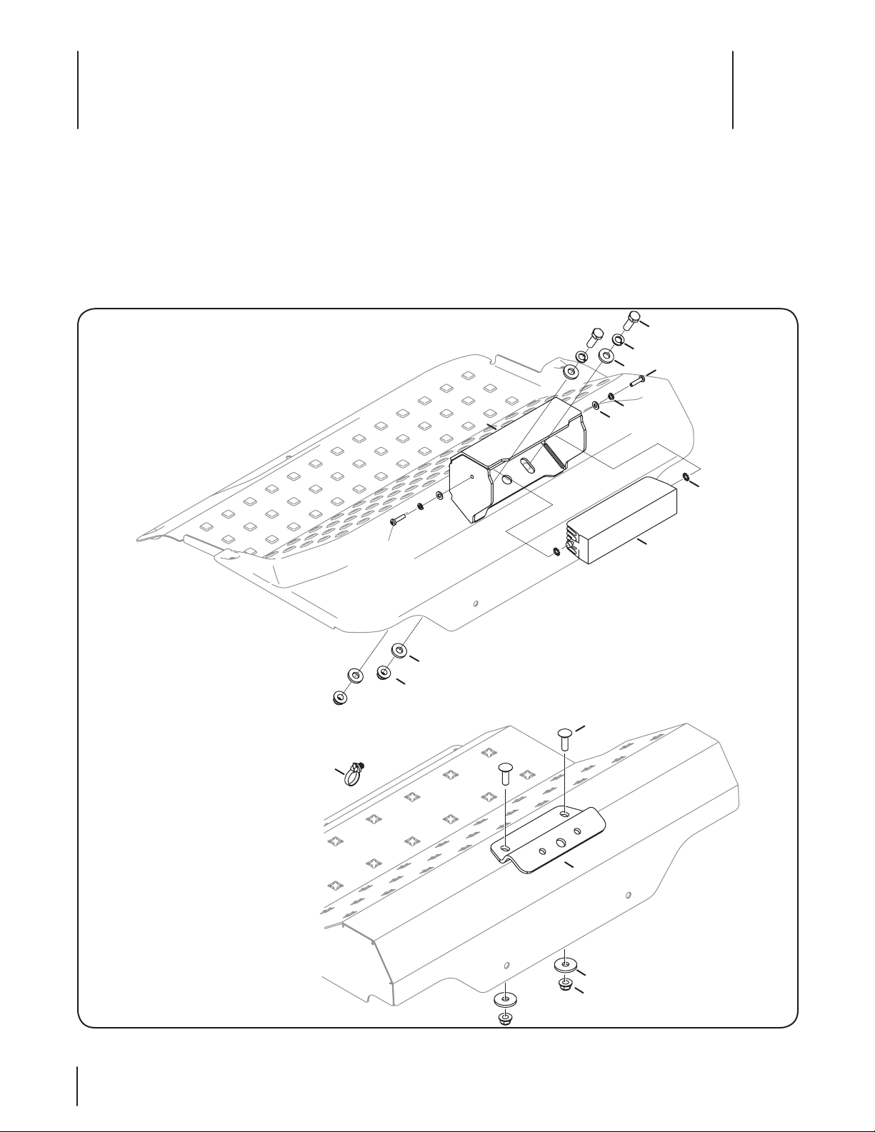
Ref. Part Number Description Qty.
1 603-05077 Headlight Bracket 1
2 703-09867 Headlight Mounting Bracket 1
3 710- 0276 Carriage Screw, ⁄-18 x 1.00 2
4 710- 0376 Hex Screw, ⁄-18 x 1.00 2
5 710- 04879 Machine Screw, #8-32 x .750 2
6 712- 04 06 3 Flange Lock Nut, ⁄-18 4
7 725-06054 Headlight Assembly 1
8 73 6- 0119 Lock Washer, ⁄ 2
9 736 -0147 External Tooth Lock Washer, #10 2
10 736- 0231 Flat Washer, .344 x 1.125 x .120 2
11 736-0722 Lock Washer, #10 2
12 736-0931 Flat Washer, .203 x .403 x .040 2
13 736-3008 Flat Washer, .344 x .750 x .120 4
14 726-0470 Cable Tie, 19 x 8.39 1
NS 725-06069A Headlight Harness 1
NS 725-06070A Headlight Adapter Harness 1
Installation
1. Using the appropriate stencil from pages 6-7 of the
manual, mark the location of the holes to be drilled in the
floorboard. There is a separate template for fabricated and
stamped floorboards.
NOTE: There are two edges for the templates, one edge is
used for steering wheel models and one edge is for lapbar
models.
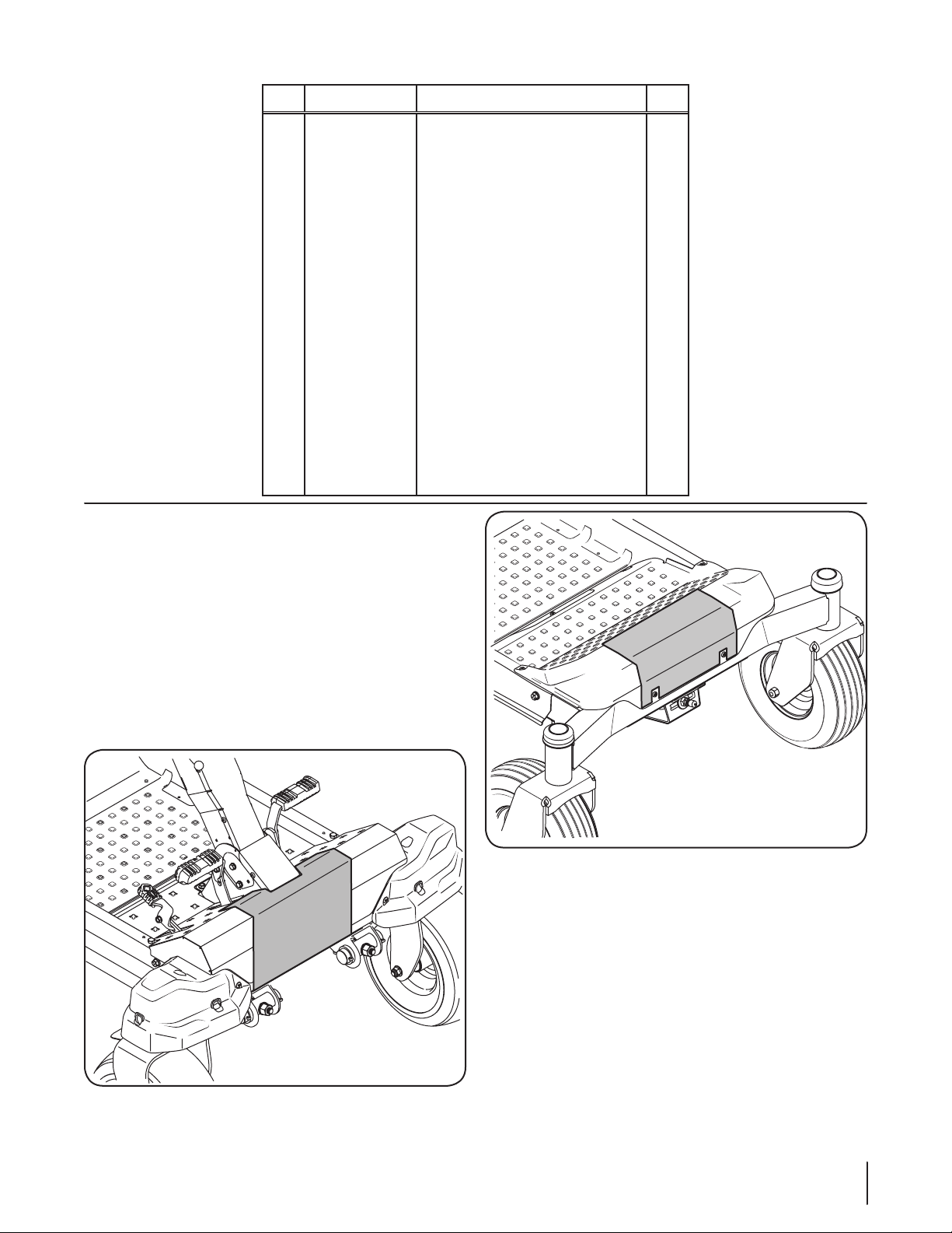
2. Align the template according to the instructions and tape
in place. See Figure 1-1 for the RZT-S and Z-Force SZ and see
Figure 1-2 for RZT-L and Z-Force L/LZ models. Center-punch
the holes to mark the location of the holes to be drilled.
Figure 1-1
Figure 1-2
3Section 1 — inStallation
Page 4
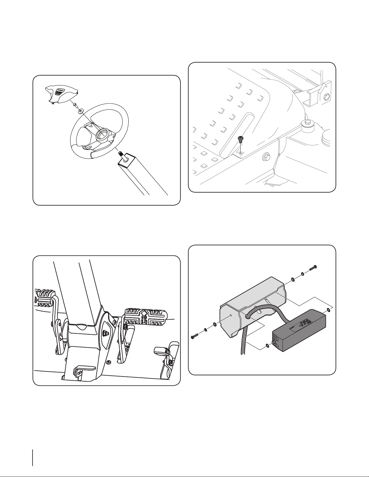
3. Before beginning installation, remove the steering wheel
from the steering wheel column on the RZT-S/Z-Force SZ
models. Remove the steering wheel by carefully removing
the steering wheel cover, then remove the hex screw
and belleville washer securing the steering wheel to the
steering wheel column. See Figure 1-3.
Figure 1-3
4. The three pedals on the RZT-S/Z-Force SZ will also have
to be removed to get the floor board off the tractor. The
drive/reverse pedals are secured with a hex screw and the
brake pedal is secured by a hex screw and flange lock nut.
See Figure 1-4. Remove the screws and the pedals.
5. On all models the floor board needs to be removed to
properly drill the mounting holes and route the wiring. To
remove the floor board, remove the screws securing it to
the frame. See Figure 1-5.
Figure 1-5
6. Drill the holes using the center-punched locations marked
in step 2 and remove burrs.
7. Feed the headlight harness adapter on the headlight
assembly (#7) through the middle hole in the welded
headlight bracket (#1). See Figure 1-6.
Figure 1-4
4 Section 1 — inStallation
Figure 1-6
NOTE: If the headlight assembly is shipped with a headlight
harness installed, it needs to be removed and then replaced
with the harness shipped with the kit.
8. Install the headlight assembly (#7) onto the headlight
bracket (#1) using two external tooth lock washers (#9), two
lock washers (#11), two flat washers (#12) and two machine
screws (#5) as shown in Figure 1-6.
Page 5

This page was intentionally left blank.
5Section 1 — inStallation
Page 6

Center and align on
steering column
5/16” Drill
Lapbar
Models
Cut-out for
1/2” Drill
5/16” Drill
Floorboard Models
Template for Stamped
Center and align on
mounting hardware
6 Section 1 — inStallation
Lapbar
Models
Cut-out for
Page 7

Template for Fabricated
Fold Fold
5/16” Drill
Floorboard Models
Center and align on steering column
1/2” Drill
5/16” Drill
FoldFold
7Section 1 — inStallation
Page 8

This page was intentionally left blank.
8 Section 1 — inStallation
Page 9
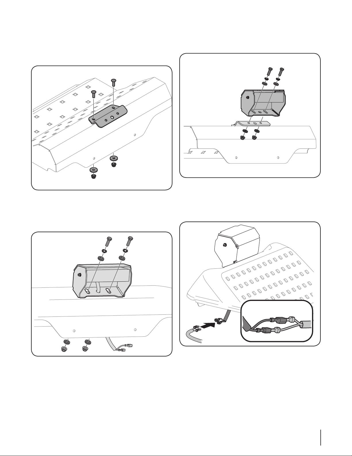
9. On tractors with a fabricated floorboard, the headlight
mounting bracket needs to be installed on the floorboard
before proceeding. Install the headlight mounting bracket
(#2) using two carriage screws (#3), two flat washers (#10)
and two flange lock nuts (#6) as shown in Figure 1-7.
Figure 1-7
10. Install the headlight bracket (#1) to the floor board on
tractors with a stamped floorboard using two hex screws
(#4), two lock washers (#8), four flat washers (#13) and two
flange lock nuts (#6) as shown in Figure 1-8.
11. Install the headlight bracket (#1) onto the headlight
mounting bracket (#2) on fabricated floorboards as shown
in Figure 1-9.
Figure 1-9
NOTE: Be sure not to damage the headlight harness
adapter when installing the headlight bracket (#1).
12. Connect the headlight harness adapter to the headlight
harness as shown in Figure 1-10.
Figure 1-8
NOTE: Be sure not to damage the headlight harness
adapter when installing the headlight bracket (#1).
Figure 1-10
9Section 1 — inStallation
Page 10

13. Place the floorboard with the headlight back onto the tractor,
but do not re-install the screws until instructed to do so.
14. Route the harness as shown in Figure 1-11 on the RZT
models. For Z-Force models skip ahead to step 15.
b. Feed the headlight wire harness along the bottom of
the frame and then up through the hole below the
seat box frame. See Figure 1-13.
Figure 1-11
a. Snap the rosebud clip into the top of the frame. See
Fi gu re 1-12.
Figure 1-12
Figure 1-13
c. Snap the rosebud clip into the frame as shown in
Figure 1-14 and connect the headlight harness to the
main harness.
Figure 1-14
10 Section 1 — inStallation
Page 11

15. Route the harness as shown in Figure 1-15 for the Z-Force
models.
Figure 1-15
a. Snap the rosebud clip into the top of the frame. See
Fi gu re 1-12.
b. Feed the headlight wire harness along the bottom
of the frame and then up through the larger
rectangular frame hole. See Figure 1-15.
c. On Z-Force L models, locate the hole on the inner
LH frame rail. Press the cable tie (#14) into the hole
and secure the wire harness against the frame rail.
On Z-Force S models, use the cable tie (#14) to secure
the headlight harness to the main wire harness.
d. Snap the rosebud clip into the frame as shown in
Figure 1-14 and connect the headlight harness to the
main harness.
16. Visually inspect the wire harness routing and confirm
clearance from all moving parts.
17. Re-install the floor board and on RZT-S and Z-Force SZ
models reinstall the steering wheel and pedals.
Operation
Turn the ignition key to the accessory position to turn the light on.
The light will stay on as long as the tractor is running. To turn the
light off, turn the tractor off and remove the key.
11Section 1 — inStallation
Page 12

CUB CADET LLC
MANUFACTURER’S LIMITED WARRANTY
FOR SEPARATELY SOLD ATTACHMENTS AND ACCESSORIES
IMPORTANT: To obtain warranty coverage owner may be required
to present an original proof of purchase and applicable maintenance
records to the servicing dealer. Please see the operator’s manual for
information on required maintenance and service intervals.
The limited warranty set forth below is given by Cub Cadet LLC with
respect to new merchandise purchased or leased and used in the
United States and/or its territories and possessions, and by MTD
Products Limited with respect to new merchandise purchased or
leased and used in Canada and/or its territories and possessions
(either entity respectively, “Cub Cadet”).
Cub Cadet warrants this product (excluding its Normal Wear Parts, as
described below) against defects in material and workmanship for
a period of two (2) years commencing on the date of original retail
purchase or lease and will, at its option, repair or replace, free of
charge, any part found to be defective in materials or workmanship.
Normal Wear Parts are warranted to be free from defects in material
and workmanship for a period of thirty (30) days from the date of
original purchase or lease. Normal wear parts include, but are not
limited to items such as: belts, blades, blade adapters, grass bags,
rider deck wheels, seats, and tires.
This limited warranty shall only apply if this product has been
operated and maintained in accordance with the Operator’s
Manual furnished with the product, and has not been subject to
misuse, abuse, neglect, accident, improper maintenance, alteration,
vandalism, theft, fire, water, or damage because of other peril or
natural disaster. Damage resulting from the installation or use of any
part, accessory or attachment not approved by Cub Cadet for use
with the product(s) covered by this manual will void your warranty as
to any resulting damage. In addition, Cub Cadet may deny warranty
coverage if the hour meter, or any part thereof, is altered, modified,
disconnected or otherwise tampered with.
HOW TO OBTAIN SERVICE: Warranty service is available, WITH
PROOF OF PURCHASE AND APPLICABLE MAINTENANCE RECORDS,
through your local authorized service dealer. To locate the dealer in
your area:
In the U.S.A.
Check your Yellow Pages, or contact Cub Cadet LLC at P.O. Box 361131,
Cleveland, Ohio 44136-0019, call 1-877-282- 8684
or log on to our website at www.cubcadet.com.
In Canada
Contact MTD Products Limited, Kitchener, ON N2G 4J1, call 1-800668-1238 or log on to our website at www.mtdcanada.com.
Without limiting the foregoing, this limited warranty does not provide
coverage in the following cases:
a. Routine maintenance items such as lubricants, filters, blade
sharpening, tune-ups, brake adjustments, clutch adjustments,
deck adjustments, and normal deterioration of the exterior
finish due to use or exposure.
b. Service completed by someone other than an authorized
service dealer.
c. Cub Cadet does not extend any warranty for products sold
or exported outside of the United States and/or Canada, and
their respective possessions and territories, except those sold
through Cub Cadet’s authorized channels of export distribution.
d. Replacement parts and\or accessories that are not genuine Cub
Cadet parts.
e. Transportation charges and service calls.
f. Commercial or Institutional Use.
There are no implied warranties, including without limitation
any implied warranty of merchantability or fitness for a
particular purpose. No warranties shall apply after the
applicable period of express written warranty above. No other
express warranties beyond those mentioned above, given by
any person or entity, including a dealer or retailer, with respect
to any product, shall bind Cub Cadet. The exclusive remedy is
repair or replacement of the product as set forth above.
The terms of this warranty provide the sole and exclusive
remedy arising from the sale and/or lease of the products
covered hereby. Cub Cadet shall not be liable for any incidental
or consequential loss or damage including, without limitation,
expenses incurred for substitute or replacement lawn care
services or for rental expenses to temporarily replace a
warranted product.
Some jurisdictions do not allow the exclusion or limitation of
incidental or consequential damages, or limitations on how long an
implied warranty lasts, so the above exclusions or limitations may not
apply to you.
In no event shall recovery of any kind be greater than the amount of
the purchase price of the product sold. Alteration of safety features
of the product shall void this warranty. You assume the risk and
liability for loss, damage, or injury to you and your property and/or to
others and their property arising out of the misuse or inability to use
the product.
This limited warranty shall not extend to anyone other than the
original purchaser or to the person for whom it was purchased as a
gift.
HOW LOCAL LAWS RELATE TO THIS WARRANTY: This limited
warranty gives you specific legal rights, and you may also have other
rights that vary in different jurisdictions.
GDOC-100177 REV. A
Cub Cadet LLC, P.O. BOX 361131 CLEVELAND, OHIO 44136-0019, Phone: 1-877-282-8684
MTD Products Limited, Kitchener, ON N2G 4J1, Phone: 1-800-668-1238
 Loading...