

Page 1
Op e r a t O r ’s Ma n u a l
Twin Rear Bagger — Model 19A30003100
WARNING
READ AND FOLLOW ALL SAFETY RULES AND INSTRUCTIONS IN THIS MANUAL
BEFORE ATTEMPTING TO OPERATE THIS MACHINE.
FAILURE TO COMPLY WITH THESE INSTRUCTIONS MAY RESULT IN PERSONAL INJURY.
CUB CADET LLC, P.O. BOX 361131 CLEVELAND, OHIO 44136-0019
Printed In USA
Form No. 769-04357D
(April 12, 2010)
Page 2
To The Owner
Thank You
Thank you for purchasing a bagging attachment manufactured
by Cub Cadet LLC. It was carefully engineered to provide
excellent performance when properly operated and maintained.
Please read this entire manual prior to operating the equipment.
It instructs you how to safely and easily set up, operate and
maintain your equipment. Please be sure that you, and any
other persons who will operate the machine, carefully follow the
recommended safety practices at all times. Failure to do so could
result in personal injury or property damage.
All information in this manual is relative to the most recent
product information available at the time of printing. Review this
manual frequently to familiarize yourself with the equipment,
its features and operation. Please be aware that this Operator’s
Manual may cover a range of product specifications for various
models. Characteristics and features discussed and/or illustrated
in this manual may not be applicable to all models. Cub Cadet
reserves the right to change product specifications, designs and
equipment without notice and without incurring obligation.
Table of Contents
Safe Operation Practices ........................................ 3
Carton Contents & Hardware Packs ...................... 6
Assembly & Installation .......................................... 8
1
If you have any problems or questions concerning this
equipment, phone your local Cub Cadet dealer or contact us
directly. Cub Cadet’s Customer Support telephone numbers,
website address and mailing address can be found on this page.
We want to ensure your complete satisfaction at all times.
Throughout this manual, all references to right and left side of the
machine are observed from the operating position.
Operation ................................................................15
Parts List ..................................................................16
Warrant y ................................................................ 20
Record Product Information
Before setting up and operating your new equipment, please
locate the model plate and record the information in the area
provided to the right. You can locate the model plate by looking
on the outside of the bagger cover. The model plate contains
the unit’s model and serial numbers. This information will be
necessary, should you seek technical support via our web site,
Customer Support Department, or with a local authorized service
dealer.
MO d e l nu M b e r
se r i a l nu M b e r
Customer Support
If you have difficulty assembling this product or have any questions regarding the controls, operation, or maintenance of
this machine, you can seek help from the experts. Choose from the options below:
Visit us on the web at www.cubcadet.com◊
Call a Customer Support Representative at (800) 965-4CUB◊
Locate your nearest Cub Cadet Dealer at (877) 282-8684◊
Write us at Cub Cadet LLC • P.O. Box 361131 • Cleveland, OH • 44136-0019◊
2
Page 3
Important Safe Operation Practices
WARNING! This symbol points out important safety instructions which, if not followed,
could endanger the personal safety and/or property of yourself and others. Read and follow
all instructions in this manual before attempting to operate this machine. Failure to comply
with these instructions may result in personal injury.
When you see this symbol. HEED ITS WARNING!
DANGER! This attachment was built to be used according to the safe operation practices in
this manual. Carelessness or error on the part of the operator can result in serious injury.
Mowers are capable of amputating hands and feet and throwing objects. Failure to observe
the following safety instructions as well as the instructions provided with your mower, could
result in serious injury or death.
2
General Operation
Read, understand, and follow all instructions on your 1.
equipment and in their manuals before attempting to
assemble and operate. Keep this manual in a safe place for
future and regular reference and for ordering replacement
parts.
To help avoid blade contact or a thrown object injury, keep 2.
bystanders, helpers, children and pets at least 75 feet from
the mower while it is in operation. Stop machine if anyone
enters the area.
Thoroughly inspect the area where the equipment is to be 3.
used. Remove all stones, sticks, wire, bones, toys, and other
foreign objects which could be picked up and thrown by
the blade(s). Thrown objects can cause serious personal
injury.
Always wear safety glasses or safety goggles during 4.
operation and while performing an adjustment or repair
to protect your eyes. Thrown objects which ricochet can
cause serious injury to the eyes.
Do not operate the mower without the discharge cover 5.
or entire grass catcher in its proper place. A missing
or damaged discharge cover or grass bag attachment
component may result in thrown objects or blade contact
injuries.
Do not put hands or feet near rotating parts or under the 6.
cutting deck. Contact with the blade(s) can amputate
hands and feet.
Shut off mower’s engine and wait for blades to come to 7.
a complete stop before unclogging mower’s discharge
opening or bagger parts.
Slow down before turning. Operate the machine smoothly. 8.
Avoid erratic operation and excessive speed. Be aware
that a grass catcher attachment can affect the handling
characteristics of your mower.
Disengage blade(s), set parking brake, stop engine and wait 9.
until the blade(s) come to a complete stop before opening
bagger attachment’s top cover, removing grass catcher,
emptying grass, unclogging chute, removing any grass or
debris, or making any adjustments.
Never leave a running machine unattended. Always turn 10.
off blade(s), place transmission in neutral, set parking
brake, stop engine and remove key before dismounting.
Your machine is designed to cut normal residential grass of 11.
a height no more than 10”. Do not attempt to mow through
unusually tall, dry grass (e.g., pasture) or piles of dry leaves.
Dry grass or leaves may contact the engine exhaust and/
or build up on the mower deck presenting a potential fire
hazard.
If situations occur which are not covered in this manual, use 12.
care and good judgment. Contact your customer service
representative for assistance.
Slope Operation
Slopes are a major factor related to loss of control and tip-over
accidents which can result in severe injury or death. Attachments
can also affect the stability of the machine. All slopes require
extra caution.
For your safety, use the slope gauge included as part of this
manual to estimate the angle of slopes before operating this
machine on a sloped or hilly area. If the slope is greater than 10
degrees as shown on the slope gauge, do not operate the mower
with the grass bag attachment installed on that area or serious
injury could result.
Do:
Mow up and down slopes, not across. Exercise extreme 1.
caution when changing direction on slopes.
Watch for holes, ruts, bumps, rocks, or other hidden 2.
objects. Uneven terrain could overturn the machine. Tall
grass can hide obstacles.
3
Page 4
Use slow speed. Choose a low enough speed setting so 3.
that you will not have to stop or shift while on the slope.
Tires may lose traction on slopes even though the brakes
are functioning properly. Always keep machine in gear
when going down slopes to take advantage of engine
braking action.
Follow the manufacturer’s recommendations for wheel 4.
weights or counterweights to improve stability.
Keep all movement on the slopes slow and gradual. Do 5.
not make sudden changes in speed or direction. Rapid
engagement or braking could cause the front of the
machine to lift and rapidly flip over backwards which could
cause serious injury.
Avoid starting or stopping on a slope. If tires lose traction, 6.
disengage the blade(s) and proceed slowly straight down
the slope.
Do Not:
Do not turn on slopes unless necessary; then, turn slowly 1.
and gradually downhill, if possible.
Do not mow near drop-offs, ditches or embankments. The 2.
mower could suddenly turn over if a wheel is over the edge
of a cliff, ditch, or if an edge caves in.
Do not try to stabilize the machine by putting your foot on 3.
the ground.
Do not use a grass catcher on steep slopes. 4.
Do not mow on wet grass. Reduced traction could cause 5.
sliding.
General Service
Before cleaning, repairing, or inspecting, make certain the 1.
blade(s) and all moving parts have stopped. Disconnect the
spark plug wire and ground against the engine to prevent
unintended starting.
Keep all nuts, bolts, and screws tight to be sure the 2.
equipment is in safe working condition.
Never tamper with your mower’s safety interlock system 3.
or other safety devices. Check their proper operation
regularly.
Never attempt to make adjustments or repairs while the 4.
mower’s engine is running.
Grass catcher components and the discharge cover are 5.
subject to wear and damage which could expose moving
parts or allow objects to be thrown. For safety protection,
frequently check components and replace immediately
with original equipment manufacturer’s (O.E.M.) parts only,
listed in this manual. Use of parts which do not meet the
original equipment specifications may lead to improper
performance and compromise safety!
Maintain or replace safety and instruction labels, as 6.
necessar y.
Safety Symbols
This table depicts and describes safety symbols that may appear on this product. Read, understand, and follow all instructions on the
machine before attempting to assemble and operate.
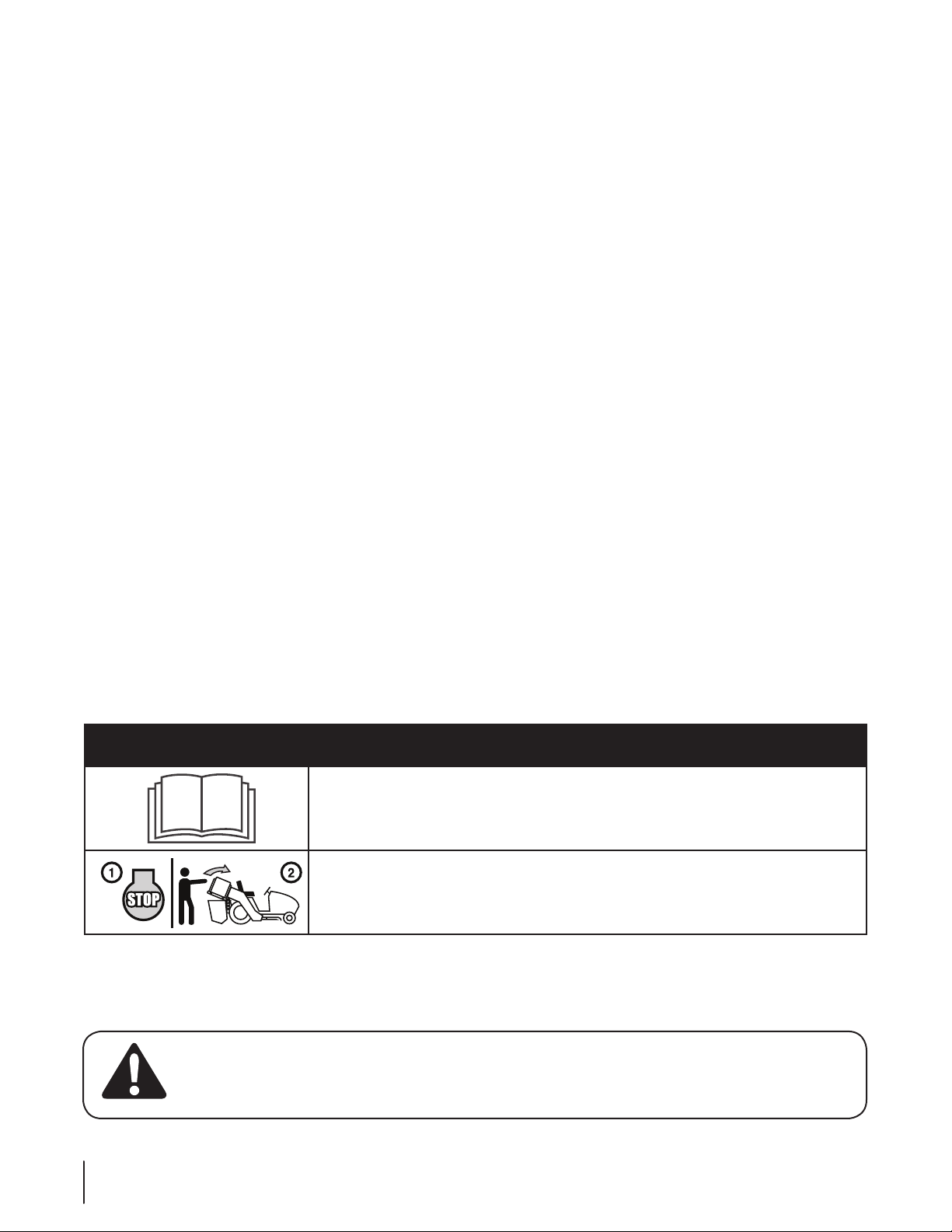
Symbol Description
READ THE OPERATOR’S MANUAL(S)
Read, understand, and follow all instructions in the manual(s) before attempting to
assemble and operate
STOP
Turn off the engine before opening the bagger cover.
WARNING! Your Responsibility—Restrict the use of this power machine to persons who read, understand and
follow the warnings and instructions in this manual and on the machine.
SAVE THESE INSTRUCTIONS!
4 se c t i O n 2 — iM p O r t a n t sa f e Op e r a t i O n pr a c t i c e s
Page 5
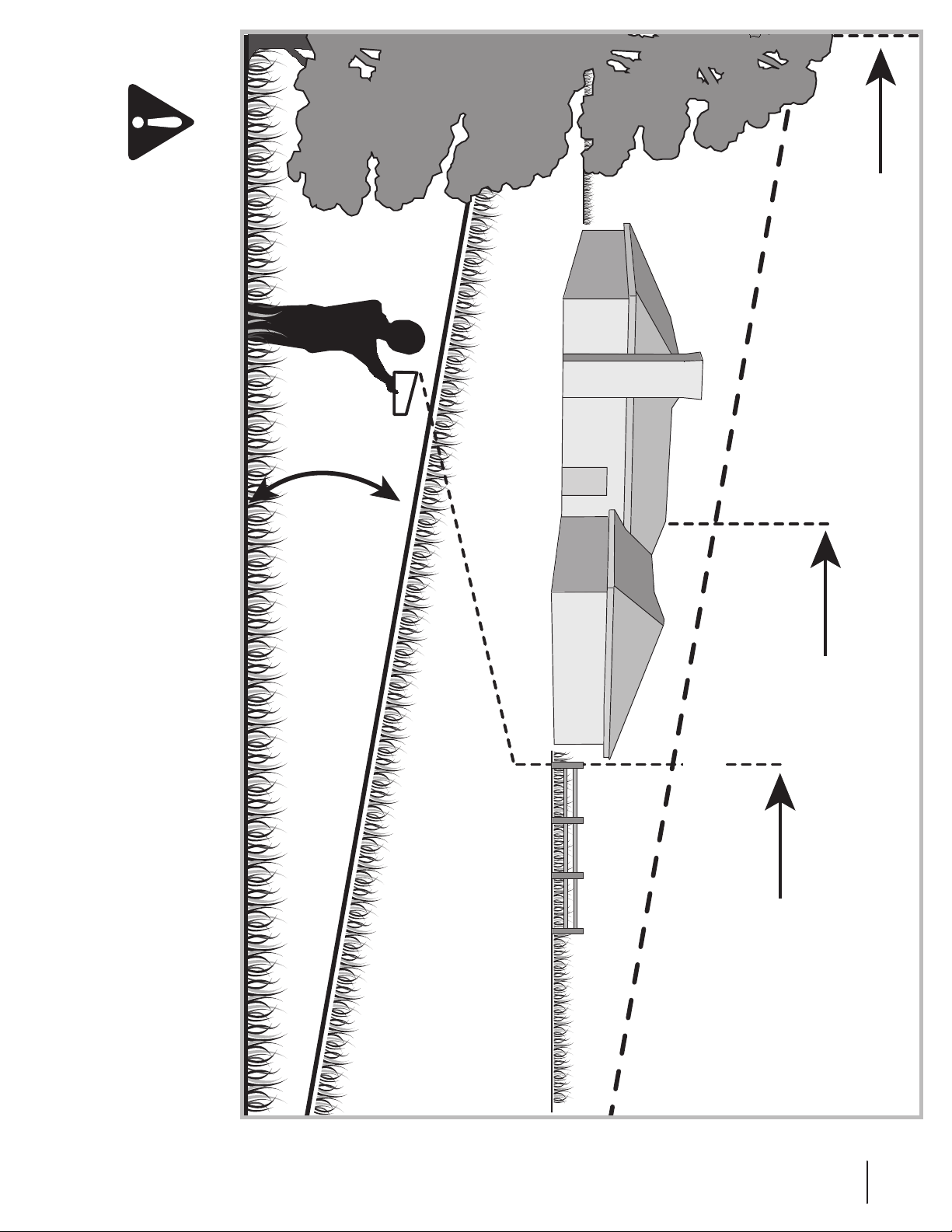
Sight and hold this level with a vertical tree...
or a corner of a building...
or a fence post
Fold along dotted line (represents a 10° slope)
10°
Use this page as a guide to determine slopes where you may safely operate your mower with a grass bag attachment installed.
WARNING! Do not operate your lawn mower with a bagger attachment on inclines with a slope in excess of 10 degrees
(a rise of approximately 1-⁄ feet every 10 feet). A riding mower with a bagger attachment could overturn and cause serious
injury. Operate riding mowers up and down slopes, never across the face of slopes.
5se c t i O n 2 — iM p O r t a n t sa f e Op e r a t i O n pr a c t i c e s
Page 6
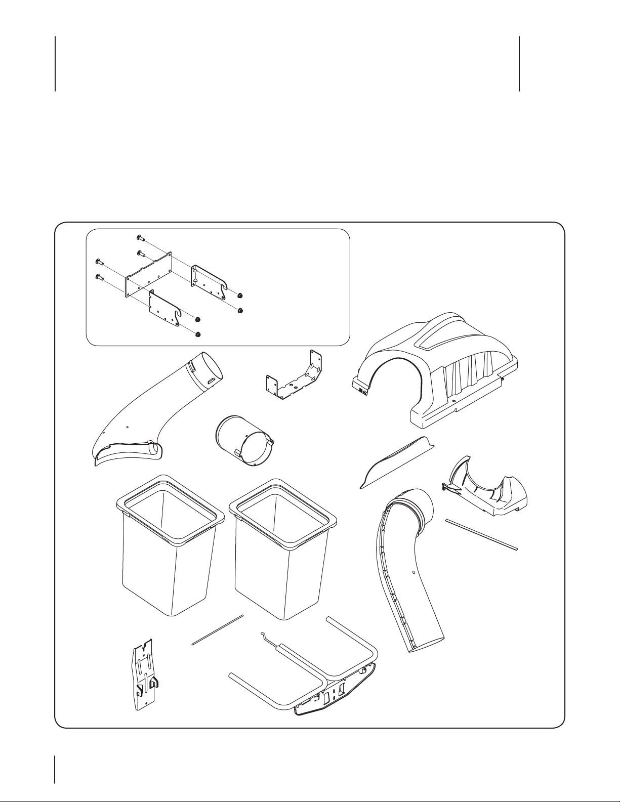
Contents of Carton
3
Before beginning installation, remove all parts from the carton to make sure everything is present. Carton contents are listed below
and shown in Fig. 3-1. Three hardware packs are included in this kit and are detailed on the following page.
Hitch Bracket Kit•
Discharge Chute Elbow•
Hitch Support•
Grass Catcher Cover•
Chute Tube Extension•
Grass Catcher Cover Screen•
Two Grass Bag Assemblies•
(3 Pcs. & Hardware)
Upper Chute Tube•
Self-Adhesive Strip•
Upper Chute Support•
Upright Support•
Hinge Cover Pin•
Bag Support Assembly•
Three Hardware Packs•
(Detailed & ill ustrated on the next pag e)
Discharge Chute
Elbow
(731-06099B)
689-00101 Hitch Bracket Kit
(3 Pcs. & Hardware)
RH Mount (789-00052)
LH Mount (789-00054)
Rear Attachment Bracket
(789-00053)
Carriage Bolts (4) (710-0276)
Flange Lock Nuts (4) (712-04063)
Hitch Support
(783-05887-0637)
Chute Tube
Extension
(7 31-0 6610)
Grass Catcher
Cover Screen
(7 31-0 650 4)
Grass Catcher
Cover
(931-0429 2)
Upper Chute
Support
(7 31-0 6497)
Grass Bag
Assemblies
(964- 04090A)
Upright Support
(683-04519-0637)
Hinge Cover Pin
( 711 - 0 4 98 8 )
Bag Support
Assembly
(683-04461-0637)
Self-Adhesive
Strip
(721-0438 8)
Upper Chute Tube
(9 31- 04 291)
Figure 3-1
6
Page 7
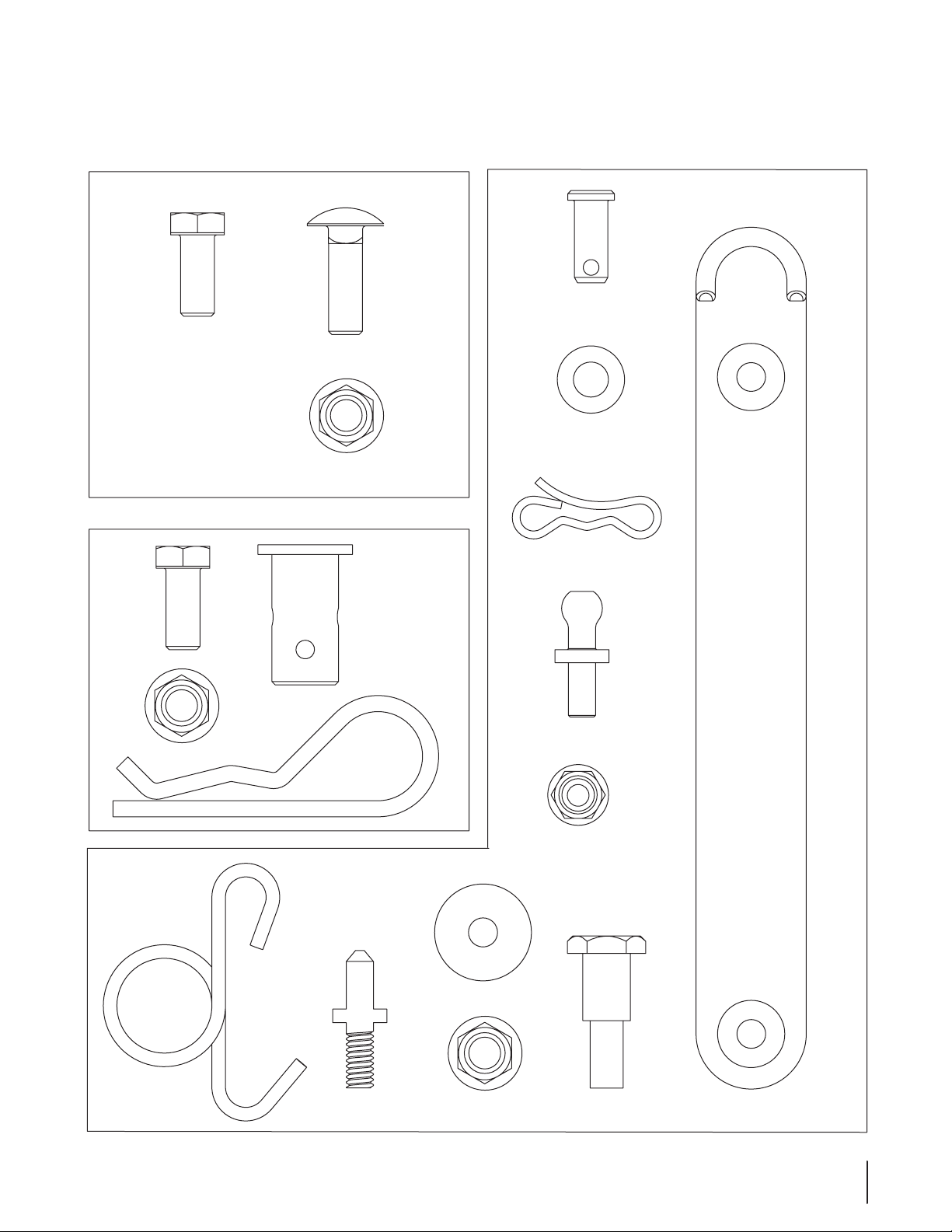
CONTENTS OF HARDWARE PACK
This grass collector kit is shipped with three loose hardware packs enclosed and one set of hardware included in the mounting bracket kit.
Please check your hardware packs against the illustrations below. The quantities for each item is listed in parenthesis.
Hardware Pack for 689-00081
Hardware Pack 689-00092B
(1)
710-3008
Hardware Pack for 689-00087
(4)
710-3008
710-0276
712-04063
(1)
(1)
(2)
711-05063
736-0204
714-04040
(2)
(1)
723-04008A
(2)
(2)
(2)
712-04063
732-04510A
(4)
711-0309A
(1)
714-0117
711-05049
(1)
(1)
(2)
736-0176
712-04063
911-04069
(2)
712-3027
(1)
(1)
738-0754
7se c t i O n 3 — cO n t e n t s O f ca r t O n
Page 8
Assembly & Installation
Side View
4
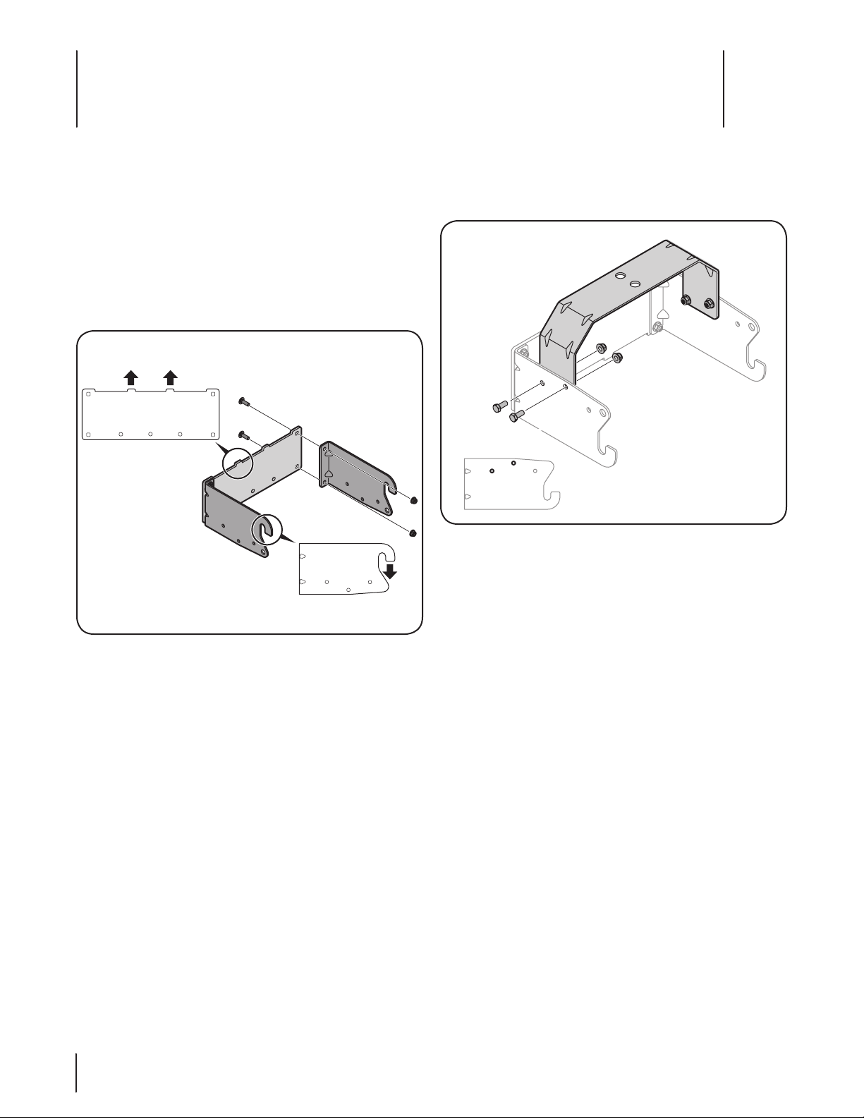
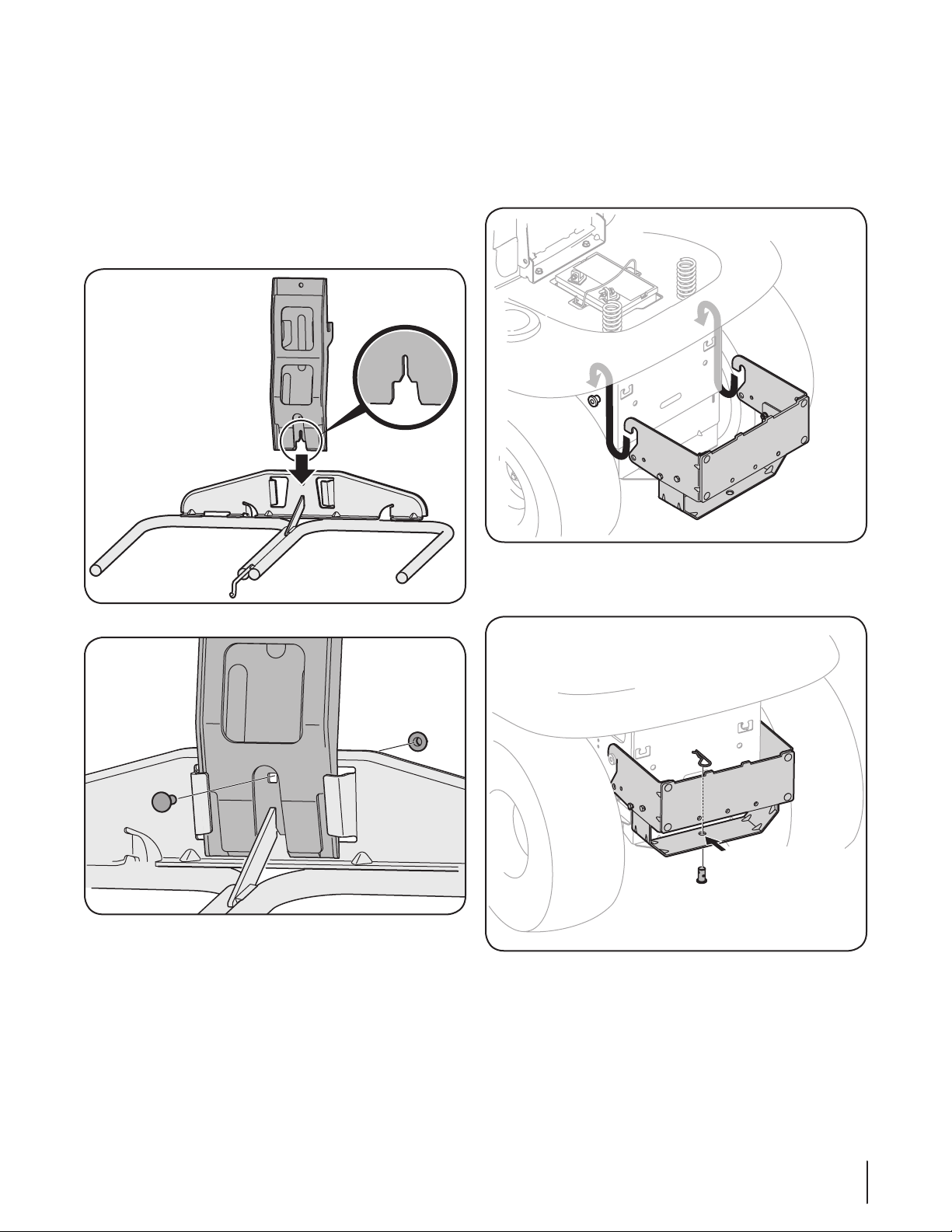
Assemble Mounting Brackets
To assemble the bagger mounting assembly, locate the hitch
bracket kit and follow these steps:
Attach the right-hand and left hand rider hitch bracket 1.
to the universal rear attachment bracket using the four
carriage bolts (710-0276) and flange lock nuts (712-04063)
packed with the mounting brackets. Position the brackets
with the hooks on the right-hand and left hand rider hitch
bracket pointing downward, and the tabs on the universal
rear attachment bracket pointing upwards. See Fig. 4-1.
Flip over assembly and mount the hitch support bracket to 2.
the mounting assembly using four 710-3008 hex bolts and
712-04063 flange lock nuts from hardware pack 689-00087.
See Fig. 4-2 for proper orientation.
Figure 4-2
Note: When attaching the hitch support, it is best to not
fully tighten the bracket at this time. This will facilitate the
mounting process in later steps, which will then require
fully tightening of this hitch support bracket.
Figure 4-1
Note: This universal mounting bracket assembly is
designed to work with other available attachments, such
as a weight kit used in conjunction with the snow blade or
snow thrower attachment. Utilize the contact information
on page 2, or contact the retailer in which you purchased
this equipment, to find out more about available
attachments for your specific tractor.
8
Page 9
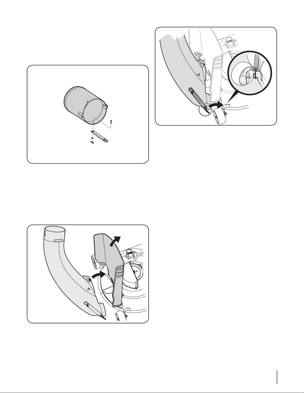
Assembling The Bag Support Assembly
Align hole on bracket
with hole on tractor
Locate the upright support bracket and the bag support
assembly. Assemble it by following these steps:
Lay the bag support assembly topside down with the 1.
mounting bracket portion facing upwards.
Insert the notched end of the vertical support bracket into 2.
the bag support assembly, as in Fig. 4-3, and secure with
a carriage bolt (710-0276) and flange lock nut (712-04063)
from hardware pack 689-00081. See Fig. 4-4.
Mount Assembly on Tractor
Install the mounting assembly on the tractor as follows:
Place the hooked ends of the bagger mounting assembly 1.
over the shoulder bolts, as in Fig. 4-5, on the tractor and
line up the hitch support hole on the mounting assembly
with the hole on the tractor’s hitch.
Figure 4-3
Figure 4-4
Figure 4-5
Install the clevis pin (711-0309A) from hardware pack 689-2.
00087 into the tractor’s hitch and the assembly’s hitch support
and secure with a hairpin clip (714-0117). See Fig. 4-6.
Figure 4-6
Note: The clevis pin can be fed down through the hitch
support and secured underneath with the hairpin clip, or
it may be easier to feed the clevis pin up through the hitch
plate hole and secure with the hairpin clip on the topside.
The latter method may be preferred since it can be easier
to insert the hairpin clip. Either way will work, the decision
should be based on operator preference.
Tighten all of the hardware securing the hitch support at 3.
this time.
9se c t i O n 4 — as s e M b l y & in s t a l l a t i O n
Page 10
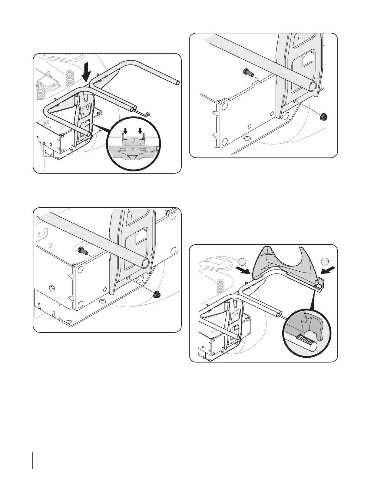
Install the bag support assembly onto the mounting 4.
Tabs
Top View
42” Decks
1
2
46” Decks
assembly on the tractor by hooking it over the cross
mounting bracket outside of the two tabs. See Fig. 4-7.
Figure 4-7
Secure the bag support assembly to the mounting assembly 5.
using a hex bolt (710-3008) and flange lock nut (712-04063)
provided in hardware pack 689-00087. See Fig. 4-8.
Figure 4-9
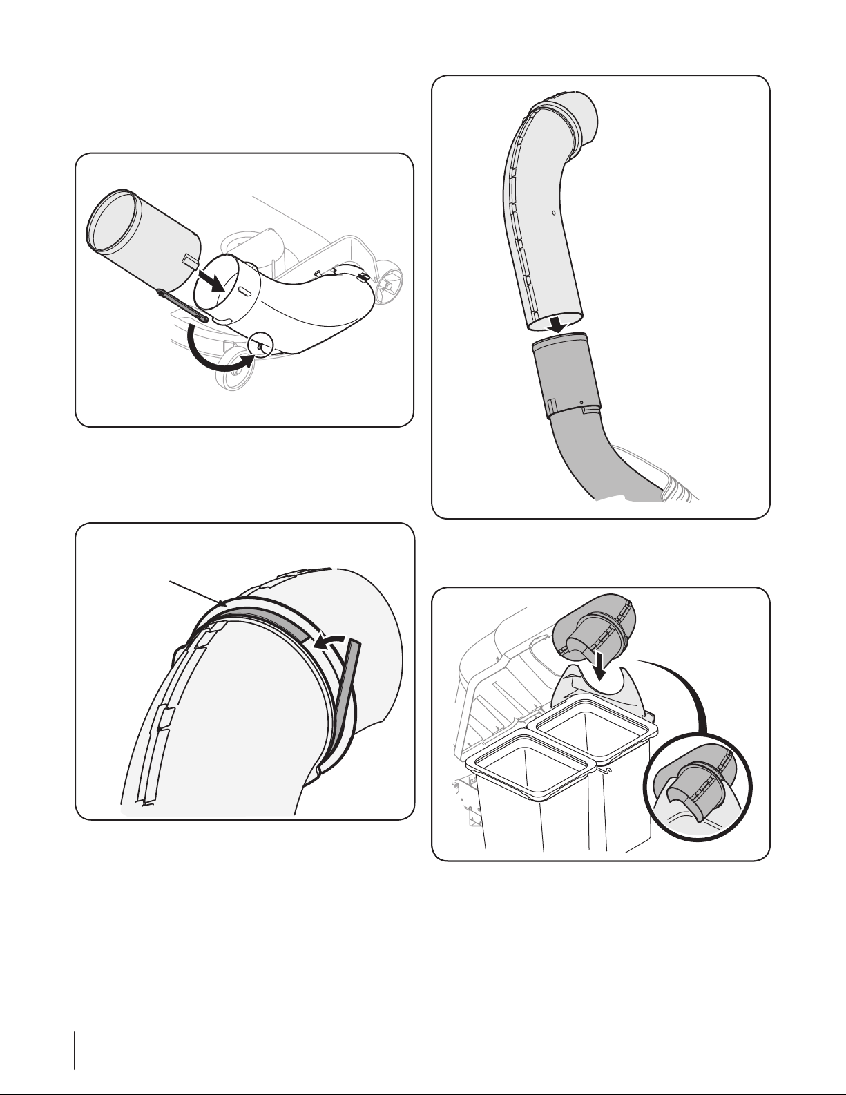
Assembling Remaining Bagger Components
Now that the mounting brackets are assembled and are in place
on the tractor, follow these steps to assemble the remaining
bagger components.
Snap the plastic upper chute support in place by first 1.
clipping the side portion onto the bag support rail with
the edge of the snap feature aligned with the red line (1), as
shown in the inset of Fig. 4-10.
Snap the front portion of the upper chute support to the 2.
bag support rail as seen in 2 of Fig. 4-10.
Figure 4-8
Note: On tractors with 42” decks the support assembly
mounts in the center hole as seen above in Fig. 4-8. On
tractors with 46” decks, the support assembly mounts in
the right hand hole as seen in Fig. 4-9.
10 se c t i O n 4 — as s e M b l y & in s t a l l a t i O n
Figure 4-10
Page 11
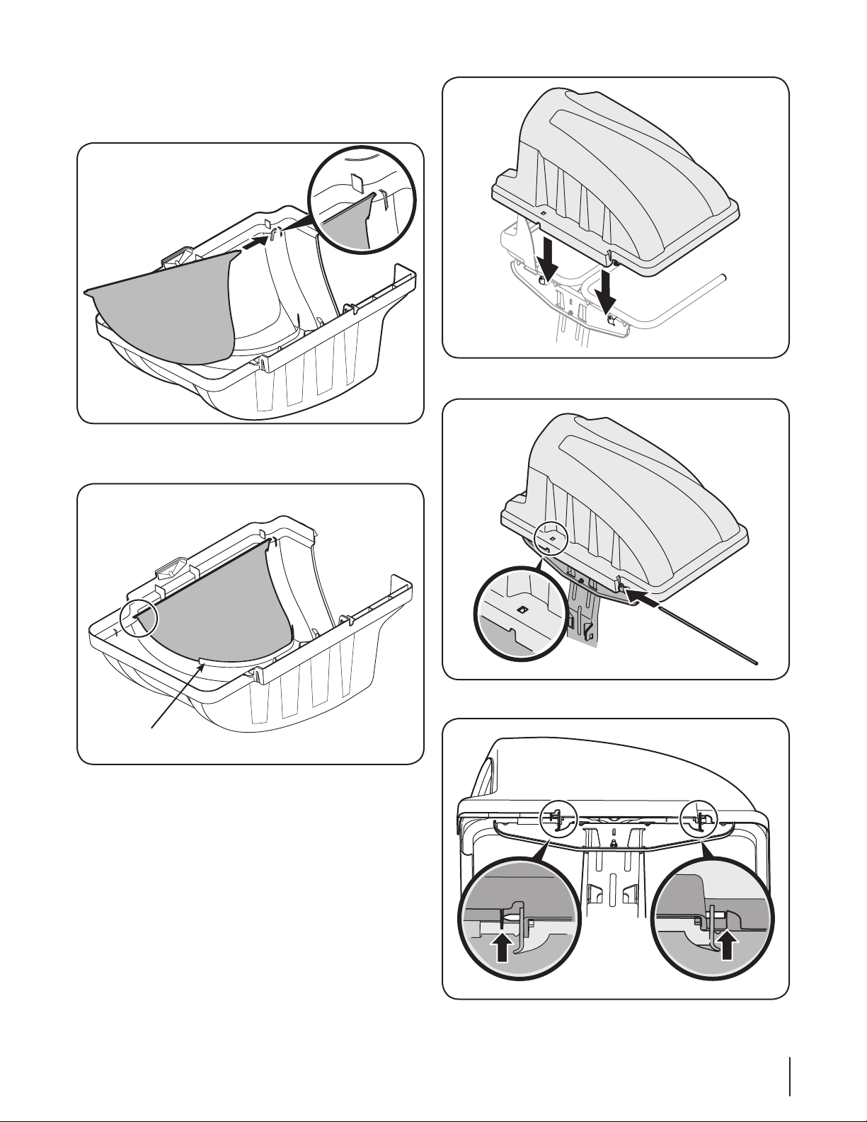
Install the bagger screen into the bagger cover by first 3.
inserting the end closest to the side with the cutout into
the mounting hole, as in Fig. 4-11. Make sure to feed the
screen under the lip, as in Fig. 4-12.
Figure 4-11
Clip in the other side by pushing the screen into the 4.
provided cutout. See Fig. 4-12.
Figure 4-13
Make sure screen sits
under the cover’s lip
Figure 4-12
Install the grass catcher cover onto the bag support 5.
assembly, as seen in Fig. 4-13. The grass catcher cover
goes inside of the two mounting tabs on the bag support
assembly.
Slide the hinge pin into the hole located on the mounting 6.
tab, as in Fig. 4-14. Use the cut-out window (See inset in
Fig. 4-14) to line up the hinge pin on the other side and
push pin all the way in until it reaches the end-stop. At this
point the pin clips into place and is secured by a tab in the
bagger cover. See Fig. 4-15.
Figure 4-14
Figure 4-15
11se c t i O n 4 — as s e M b l y & in s t a l l a t i O n
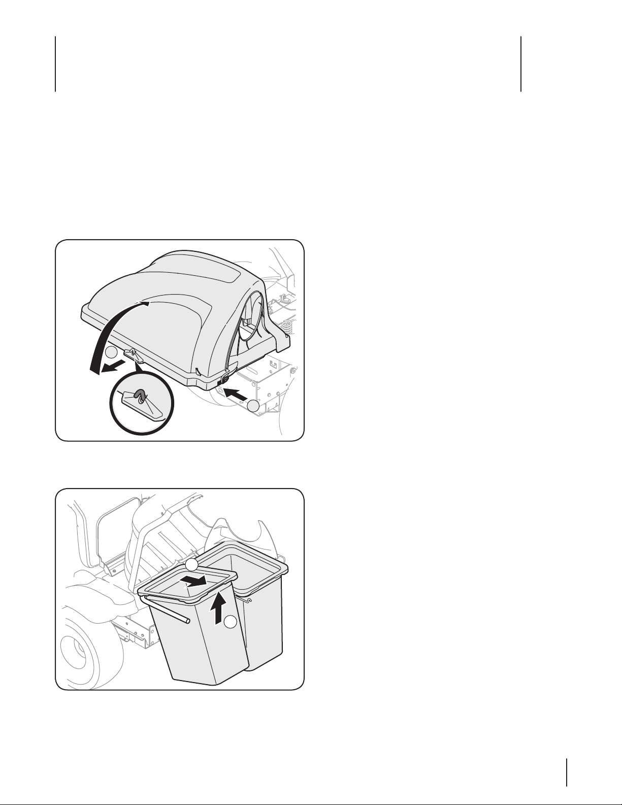
Page 12
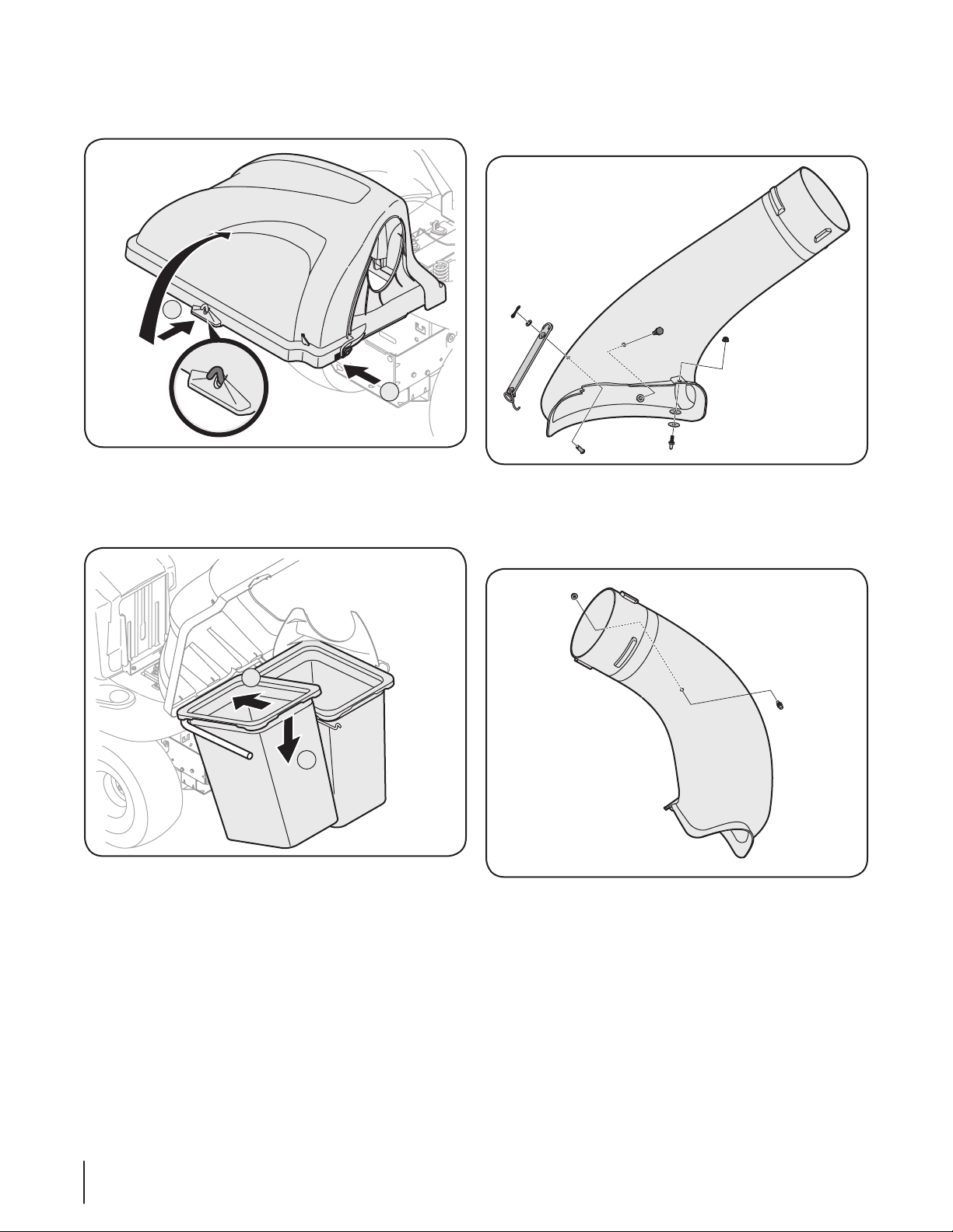
Open Hood by pushing in on the rear, right-side tab with 7.
1
2
1
2
your right hand, as seen in 1 of Fig. 4-16, and lifting the cover
with your left hand in the center rear of the bagger cover, 2.
Figure 4-16
Install both grass bags onto the bag support assembly by 8.
inserting the front edge in first (1), as seen in Fig. 4-17,
and setting the back edge down (2) until it fits into the
assembly.
Install the shoulder bolt (738-0754) into the chute elbow 11.
from the top side and secure inside the chute elbow using
a flange lock nut (712-04063) from the same hardware pack
(689-00092B). See Fig. 4-18.
Figure 4-18
Install a grass-catcher pin (911-04069) from hardware pack 689-12.
00092B into the hole provided in the upper portion of the
chute elbow and secure with a flange lock nut (712-3027). See
Fi g. 4 -19.
Figure 4-17
Install one of the rubber chute straps onto the chute elbow 9.
using one of the supplied clevis pins (711-05063), washer (736-
0204) and Bow-tie cotter pins (714-04040) from hardware
pack 689-00092B. See Fig. 4-18. Secure the end of the strap
utilizing the hole furthest from the end, insert the torsion
spring hook (732-04510A) into the other end.
Install the deck mounting pin (711-05049) up into the chute 10.
elbow using two flat washers (736-0176) from hardware pack
689-00092B and secure with a flange lock nut (712-3027), as
seen in Fig. 4-18.
12 se c t i O n 4 — as s e M b l y & in s t a l l a t i O n
Figure 4-19
Page 13
Install the other rubber strap onto the chute tube extension 13 .
using the remaining clevis pin, flat washer and bow-tie cotter
pin from hardware pack 689-00092B. Attach the end with the
hole closest to the end of the strap, as seen in Fig. 4-20. This
will make it easier to grab onto the strap to pull, stretch and
hook onto the grass-catcher pin previously installed on the
chute elbow in the previous step.
Figure 4-20
Figure 4-22
With the tractor’s discharge chute raised up and held open, 14.
install the chute elbow over the chute opening by placing
the deck mounting pin in the hole provided, as seen in
Fig. 4-21, then secure the elbow to the deck by hooking
the retainer strap torsion spring hook over the deck wheel
mounting bracket a seen in Fig. 4-22.
Note: On decks without deck wheels, hook the retainer
strap into the hole provided in the flange on the front-side
of the cutting deck.
Figure 4-21
13se c t i O n 4 — as s e M b l y & in s t a l l a t i O n
Page 14
Install the chute tube extension onto the chute elbow 15 .
Flange
by lining up the tabs and sliding the adapter over the
chute elbow, as in Fig. 4-23. Secure the chute adapter by
stretching the chute strap and hooking it onto the grasscatcher pin previously installed.
Figure 4-23
Peel the backing off of the self-adhesive foam strip (721-16.
04388) that has been included with your grass collector. Apply
it to the upper chute, flush against the flange as shown in Fig.
24.
Figure 4-25
Note: The groove on the upper chute should be aligned
with the upper chute support, as seen in the inset of Fig.
4-26.
Figure 4-24
With the grass catcher cover open, install the discharge 17.
chute over the chute extension tube, as seen in Fig. 4-25,
and rest the top end into the upper chute support installed
on the right-hand side of the bag support assembly. See
Fig. 4-26.
14 se c t i O n 4 — as s e M b l y & in s t a l l a t i O n
Figure 4-26
Page 15
Operation
1
2
2
1
5
Bagger Usage
NOTE: When both grass bags are full, place the tractor on a firm,
level surface, disengage the PTO, turn the tractor engine off and
set the parking brake.
Flip Seat up.1.
Open the grass bag cover by pushing in on the rear, right-2.
side tab with your right hand, as seen in 1 of Fig. 5-1, and
lifting the cover with your left hand in the center rear of the
bagger cover, 2. Do not remove the chute tube assembly
from the tractor.
Empty the grass clippings at a proper disposal sight, use 4.
the handle at the bottom of each grass bag. Holding the
bag firmly, empty the contents
Replace grass bags, close lid, flip down seat, restart your 5.
tractor and resume cutting your grass.
Figure 5-1
Remove the grass bags by lifting these up (1 in Fig. 5-2) and 3.
moving the bags away from the bag support assembly (2).
Figure 5-2
15
Page 16
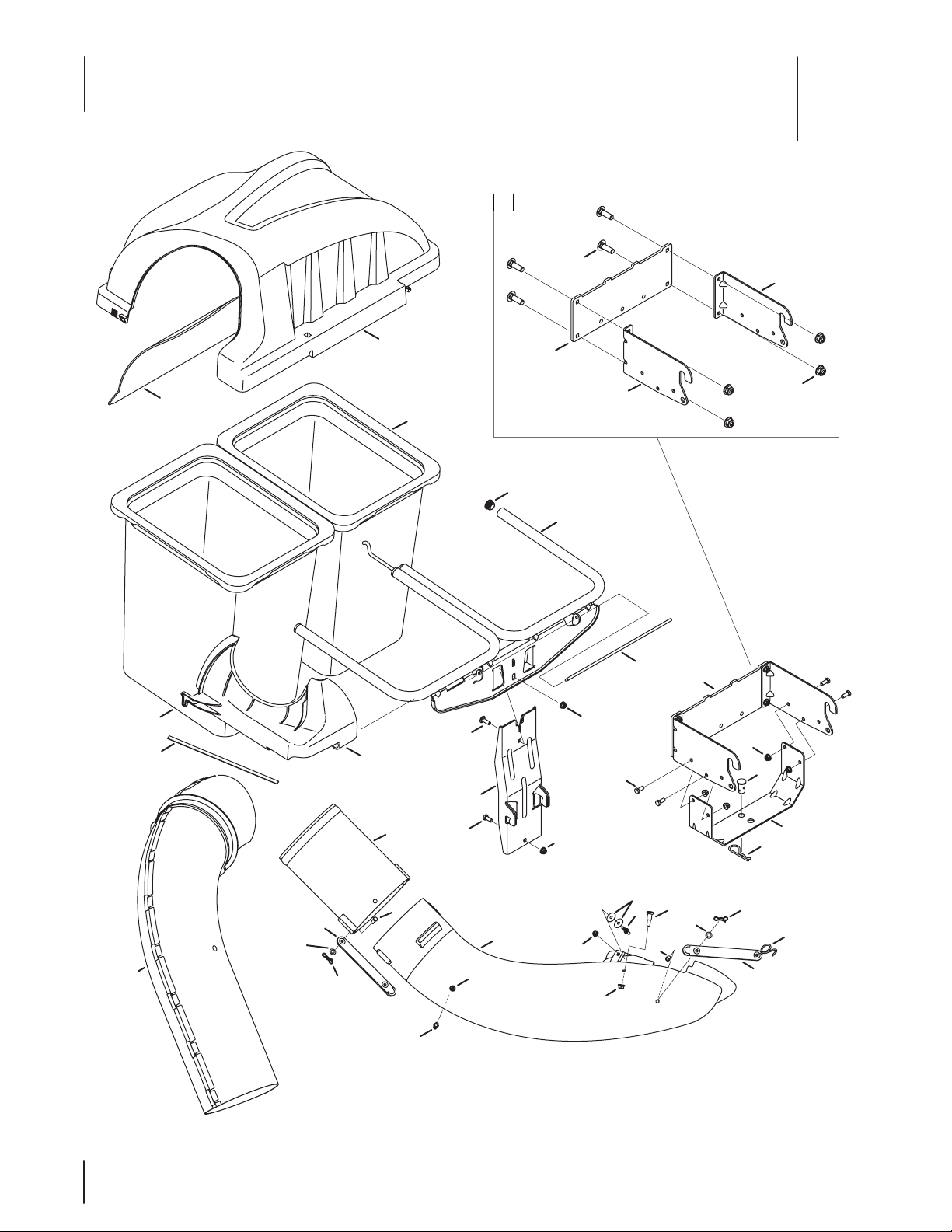
Twin Rear Bagger 19A30003100 Parts List
5
31
5
25
2
4
26
32
3
26
5
28
23
22
30
27
29
11
6
31
11
11
7
16
17
15
19
1
14
10
8
6
16
12
11
20
21
9
19
12
11
10
24
13
14
18
15
Page 17

Ref. Part Number Description
1. 931- 042 91 Upper Chute Assembly
2. 931- 042 92 Double Bagger Cover Assembly
3. 731- 064 97 Upper Chute Support
4. 731- 06 504 Bagger Cover Screen
5. 710 -0276 Carriage Screw, 5/16-18 x 1.00”
6. 710 -300 8 Hex Head Screw, 5/16-18 x .75”
7. 711 - 0 30 9 A Clevis Pin, .62” Dia.
8. 911 - 0 4 0 6 9 Grass-catcher Pin, 1/4-20
9. 7 11 - 05 0 4 9 Attachment Pin, 1/4 x 0.66 Lg.
10. 7 11 - 05 0 6 3 Clevis Pin, 5/16 x .75 Lg.
11. 712 -0 4 06 3 Flange Lock Nut, 5/16-18
12 . 712 -30 27 Flange Lock Nut, 1/4-20
13. 71 4 - 0 117 Internal Cotter Pin, .148 x 3.00
14. 714-04040 Bow-Tie Cotter Pin, 72
15. 723-04008A Chute Strap, 6.00 Lg.
16. 731-06099B Bagger Discharge Chute, Elbow
17. 731- 06 610 Bagger Chute Adapter, 7 In.
18. 732- 04510A Torsion Spring Hook
19. 736-0204 Flat Washer, .344 x .62 x .033
20. 73 6- 017 6 Flat Washer, .265 x .938 x .120
21. 738-0754 Shoulder Screw, .437 x .54
22. N/A* Mounting Bracket, RH
23. N/A* Universal Mounting Bracket
24. 783-05887-0637 Universal Bracket Support
25. N/A* Mounting Bracket, LH
26. 964-04090A Grass-bag Assembly
27. 683-04461-0637 Double Bag Support Assembly
28. 683-04519-0637 Vertical Support Bracket
29. 7 11- 0 4 9 8 8 Cover Hinge Pin
30. 735-0246A End Plug
31. 689 -00101 Mounting Bracket Kit (Incl. ref. 22,
32. 721- 043 88 Self-Adhesive Foam Strip
*Order Reference 31
17se c t i O n 5 — tw i n re a r ba g g e r pa r t s li s t
Page 18

Notes
18
Page 19

19
Page 20

CUB CADET LLC
MANUFACTURER’S LIMITED WARRANTY
FOR SEPARATELY SOLD ATTACHMENTS AND ACCESSORIES
IMPORTANT: To obtain warranty coverage owner may be required
to present an original proof of purchase and applicable maintenance
records to the servicing dealer. Please see the operator’s manual for
information on required maintenance and service intervals.
The limited warranty set forth below is given by Cub Cadet LLC with
respect to new merchandise purchased or leased and used in the United
States and/or its territories and possessions, and by MTD Products
Limited with respect to new merchandise purchased or leased and
used in Canada and/or its territories and possessions (either entity
respectively, “Cub Cadet”).
Cub Cadet warrants this product (excluding its Normal Wear Parts,
as described below) against defects in material and workmanship for
a period of two (2) years commencing on the date of original retail
purchase or lease and will, at its option, repair or replace, free of charge,
any part found to be defective in materials or workmanship.
Normal Wear Parts are warranted to be free from defects in material and
workmanship for a period of thirty (30) days from the date of original
purchase or lease. Normal wear parts include, but are not limited to
items such as: belts, blades, blade adapters, grass bags, rider deck
wheels, seats, and tires.
This limited warranty shall only apply if this product has been operated
and maintained in accordance with the Operator’s Manual furnished
with the product, and has not been subject to misuse, abuse, neglect,
accident, improper maintenance, alteration, vandalism, theft, fire, water,
or damage because of other peril or natural disaster. Damage resulting
from the installation or use of any part, accessory or attachment not
approved by Cub Cadet for use with the product(s) covered by this
manual will void your warranty as to any resulting damage. In addition,
Cub Cadet may deny warranty coverage if the hour meter, or any part
thereof, is altered, modified, disconnected or otherwise tampered with.
HOW TO OBTAIN SERVICE: Warranty service is available, WITH PROOF
OF PURCHASE AND APPLICABLE MAINTENANCE RECORDS, through
your local authorized service dealer. To locate the dealer in your area:
In the U.S.A.:
Check your Yellow Pages, or contact Cub Cadet LLC at P.O. Box 361131,
Cleveland, Ohio 44136-0019, call 1-877-282- 8684
or log on to our website at www.cubcadet.com.
In Canada:
Contact MTD Products Limited, Kitchener, ON N2G 4J1, call 1-800-6681238 or log on to our website at www.mtdcanada.com.
Without limiting the foregoing, this limited warranty does not provide
coverage in the following cases:
a. Routine maintenance items such as lubricants, filters, blade
sharpening, tune-ups, brake adjustments, clutch adjustments, deck
adjustments, and normal deterioration of the exterior finish due to
use or exposure.
b. Service completed by someone other than an authorized service
dealer.
c. Cub Cadet does not extend any warranty for products sold or
exported outside of the United States and/or Canada, and their
respective possessions and territories, except those sold through
Cub Cadet’s authorized channels of export distribution.
d. Replacement parts and\or accessories that are not genuine Cub
Cadet parts.
e. Transportation charges and service calls.
f. Commercial or Institutional Use.
There are no implied warranties, including without limitation any
implied warranty of merchantability or fitness for a particular
purpose. No warranties shall apply after the applicable period of
express written warranty above. No other express warranties beyond
those mentioned above, given by any person or entity, including a
dealer or retailer, with respect to any product, shall bind Cub Cadet.
The exclusive remedy is repair or replacement of the product as
set forth above. The terms of this warranty provide the sole and
exclusive remedy arising from the sale and/or lease of the products
covered hereby. Cub Cadet shall not be liable for any incidental or
consequential loss or damage including, without limitation, expenses
incurred for substitute or replacement lawn care services or for rental
expenses to temporarily replace a warranted product.
Some jurisdictions do not allow the exclusion or limitation of incidental
or consequential damages, or limitations on how long an implied
warranty lasts, so the above exclusions or limitations may not apply to
you.
In no event shall recovery of any kind be greater than the amount of the
purchase price of the product sold. Alteration of safety features of the
product shall void this warranty. You assume the risk and liability for
loss, damage, or injury to you and your property and/or to others and
their property arising out of the misuse or inability to use the product.
This limited warranty shall not extend to anyone other than the original
purchaser or to the person for whom it was purchased as a gift.
HOW LOCAL LAWS RELATE TO THIS WARRANTY: This limited warranty
gives you specific legal rights, and you may also have other rights that
vary in different jurisdictions.
Cub Cadet LLC, P.O. BOX 361131 CLEVELAND, OHIO 44136-0019, Phone: 1-877-282-8684
GDOC-100177 REV. A
MTD Products Limited, Kitchener, ON N2G 4J1, Phone: 1-800-668-1238
Page 21

Ma n u a l d e l o p e r a d o r
Embolsadora trasera doble — Modelo 19A30003100
ADVERTENCIA
LEA Y RESPETE TODAS LAS NORMAS DE SEGURIDAD E INSTRUCCIONES INCLUIDAS EN ESTE
MANUAL ANTES DE INTENTAR HACER FUNCIONAR ESTA MÁQUINA.
SI NO RESPETA ESTAS INSTRUCCIONES PUEDE PROVOCAR LESIONES PERSONALES.
CUB CADET LLC, P.O. BOX 361131 CLEVELAND, OHIO 44136-0019
Impreso en Estados Unidos de América
Page 22

Al propietario
Gracias
Gracias por comprar un accesorio embolsador doble fabricado
por Cub Cadet LLC. El mismo ha sido diseñado cuidadosamente
para brindar excelente rendimiento si se lo opera y mantiene
correctamente.
Por favor lea todo este manual antes de hacer funcionar el
equipo. Le indica cómo configurar, operar y mantener el
accesorio de manera fácil y segura. Por favor cerciórese de
que usted o cualquier otra persona que opere la máquina siga
cuidadosamente y en todo momento las prácticas de seguridad
recomendadas. En caso de no hacerlo podrían producirse
lesiones personales o daños materiales.
Toda la información contenida en este manual hace referencia
a la más reciente información de producto disponible en el
momento de la impresión. Revise el manual frecuentemente
para familiarizarse con el accesorio, sus características y
funcionamiento. Por favor tenga en cuenta que este Manual
del Operador puede cubrir una gama de especificaciones de
producto para diferentes modelos.
Índice
Medidas importantes de seguridad .................... 23
Contenido de la caja y paquetes de elementos de
ferretería ............................................................ 26
Armado e instalación ............................................ 28
1
Es posible que las características y funciones incluidas y/o
ilustradas en este manual no se apliquen a todos los modelos.
Cub Cadet LLC se reserva el derecho de modificar las
especificaciones de los productos, los diseños y el equipo sin
previo aviso y sin generar responsabilidad por obligaciones de
ningún tipo.
Si tiene algún problema o duda respecto a este accesorio,
llame a su distribuidor de servicio Cub Cadet local autorizado o
póngase en contacto directamente con nosotros. Los números
de teléfono, dirección del sitio Web y dirección postal de la
Asistencia al Cliente de Cub Cadet se encuentran en esta página.
Queremos garantizar su entera satisfacción en todo momento.
En este manual, las referencias al lado derecho o izquierdo de la
máquina se observan desde la posición del operador.
Funcionamiento .................................................... 35
Lista de piezas ........................................................16
Garantía ................................................................. 36
Registro de información de producto
Antes de configurar y hacer funcionar su equipo nuevo, por favor
localice la placa de modelo en el equipo y registre la información
en el espacio de la derecha. Podrá localizar la placa de modelo
en la parte superior de la cubierta de la embolsadora. Si tiene
que solicitar soporte técnico a través de nuestro sitio web, el
Departamento de Asistencia al Cliente, o de un distribuidor de
servicio autorizado local, necesitará esta información.
nú M e r O d e M O d e l O
nú M e r O d e s e r i e
Asistencia al Cliente
Por favor, NO devuelva la máquina al minorista o distribuidor sin ponerse en contacto primero con el Departamento de
Asistencia al Cliente.
En caso de tener problemas para montar este producto o de tener dudas con respecto a los controles, funcionamiento
o mantenimiento de esta máquina, puede solicitar la ayuda de los expertos. Elija entre las opciones que se presentan a
continuación:
Visite nuestro sitio web en www.cubcadet.com◊
Llame a un representante de Asistencia al Cliente al (800) 965-4CUB◊
Encuentre la red más cercana de distribuidores Cub Cadet en (877) 282-8684◊
Escríbanos a Cub Cadet LLC • P.O. Box 361131 • Cleveland, OH • 44136-0019◊
22
Page 23

Medidas importantes de seguridad
¡ADVERTENCIA! La presencia de este símbolo indica que se trata de instrucciones
importantes de seguridad que se deben respetar para evitar poner en peligro su seguridad
personal y/o material y la de otras personas. Lea y cumpla todas las instrucciones de este
manual antes de intentar operar esta máquina. Si no respeta estas instrucciones puede
causar lesiones personales.
CUANDO vea este símbolo. ¡TENGA EN CUENTA LAS ADVERTENCIAS!
¡PELIGRO! Este accesorio está diseñado para ser usado respetando las normas de seguridad
contenidas en este manual. Un descuido o error por parte del operador puede ocasionar
lesiones graves. Una cortadora es capaz de amputar manos y pies y de arrojar objetos
con gran fuerza. Si no se observan las siguientes instrucciones de seguridad junto con las
instrucciones suministradas con la cortadora, se puede ocasionar lesiones graves e incluso la
muerte.
2
Funcionamiento general
Lea, comprenda y respete todas las instrucciones que 1.
figuran en el equipo y en los manuales antes de intentar
armarlo y hacerlo funcionar. Guarde este manual en un
lugar seguro para consultas futuras y periódicas, así como
para solicitar repuestos.
Para ayudar a evitar una lesión por contacto con las 2.
cuchillas o con un objeto que sea arrojado, mantenga a las
personas que observan, a los ayudantes, niños y mascotas
alejados a no menos de 25 metros de la máquina mientras
está funcionando. Detenga la máquina si alguien entra en
la zona.
Revise minuciosamente el área donde se va a usar el 3.
equipo. Retire todas las piedras, palos, cables, huesos,
juguetes y otros objetos extraños que podrían ser
recogidos y arrojados por la acción de las cuchillas. Los
objetos arrojados por la máquina pueden causar lesiones
graves.
Para protegerse los ojos, utilice siempre gafas o lentes de 4.
seguridad mientras opera la máquina o mientras la ajusta
o repara. Los objetos arrojados que rebotan pueden causar
lesiones oculares graves.
Nunca opere la cortadora de césped sin tener bien 5.
colocada la cubierta de descarga o el colector de césped.
Si falta o está dañada la cubierta de descarga o un
componente del accesorio embolsador puede resultar
en lesiones por contacto con la cuchilla o con objetos
arrojados.
No ponga las manos ni los pies cerca de las piezas 6.
rotatorias ni debajo de la plataforma de corte. El contacto
con las cuchillas puede resultar en la amputación de una
mano o pie.
Apague el motor de la cortadora de césped y espere que 7.
las cuchillas se detengan totalmente antes de desbloquear
la abertura de descarga de la cortadora o las piezas de la
embolsadora.
Reduzca la velocidad antes de girar. Opere la máquina 8.
de forma pareja. Evite el funcionamiento errático y la
velocidad excesiva. Tenga en cuenta que el accesorio
colector de césped puede afectar las características de
manejo de su cortadora.
Desenganche las cuchillas, coloque el freno de mano, 9.
detenga el motor y espere hasta que las cuchillas se
detengan totalmente antes de abrir la cubierta superior del
accesorio embolsador, sacar el colector de césped, vaciar
los recortes, desbloquear el canal, retirar cualquier residuo
o desecho, o realizar cualquier ajuste.
Nunca deje la máquina en funcionamiento sin vigilancia. 10.
Apague siempre las cuchillas, coloque la transmisión en
neutral, coloque el freno de mano, detenga el motor y
retire la llave antes de bajarse del vehículo.
Su máquina fue diseñada para cortar césped residencial 11 .
normal, con una altura no mayor a 10”. No intente cortar
pasto demasiado crecido y seco (por ej., pastura) ni pilas
de hojas secas. El pasto y las hojas secas pueden entrar
en contacto con el escape del motor y/o acumularse en la
plataforma de la cortadora de césped, convirtiéndose en
un peligro de incendio.
Si se presentan situaciones que no están previstas en este 12.
manual, sea cuidadoso y use el sentido común. Póngase en
contacto con su representante de atención al cliente para
solicitar asistencia.
Funcionamiento en pendientes
Las pendientes son un factor importante en los accidentes
ocasionados por pérdida de control y vuelcos que pueden causar
lesiones graves e incluso la muerte. Los accesorios tambíen
pueden afectar la estabilidad de la máquina. La operación en
pendiente requiere mayor precaución.
Para seguridad, use el medidor de pendientes que se incluye
como parte de este manual para estimar el ángulo de la
pendiente antes de hacer funcionar la máquina en una zona
inclinada. Si la pendiente es mayor a 10 grados en el medidor, no
opere la cortadora con el accesorio embolsador en ese sector,
pues podría causar lesiones graves.
Haga lo siguiente:
Corte hacia arriba y abajo de las pendientes, no en forma 1.
transversal. Tenga sumo cuidado al cambiar de dirección
en una pendiente.
Esté atento a los hoyos, surcos, baches, rocas, u otros 2.
objetos ocultos. El terreno desnivelado puede voltear la
máquina. El pasto alto puede ocultar obstáculos.
23
Page 24

Conduzca a baja velocidad. Elija una velocidad lo 3.
suficientemente baja como para no tener que detenerse
o cambiar de marcha mientras está en la pendiente. Los
neumáticos pueden perder tracción en las pendientes aún
cuando los frenos funcionen correctamente. Mantenga
la máquina siempre en velocidad cuando desciende una
pendiente, para poder frenar con el motor.
Siga las recomendaciones del fabricante sobre pesos y 4.
contrapesos de las ruedas, para mejorar la estabilidad.
Haga que todos los movimientos en las pendientes sean 5.
lentos y graduales. No cambie repentinamente la velocidad
ni la dirección. Un frenado o cambio de velocidad
repentinos pueden causar que el frente de la máquina se
levante y dé una voltereta hacia atrás, lo que podría causar
lesiones graves.
Evite arrancar o detenerse en una pendiente. Si los 6.
neumáticos pierden tracción, desenganche las cuchillas y
descienda lentamente la pendiente.
No haga lo siguiente:
No gire en una pendiente a menos que sea imprescindible. 1.
De ser posible, gire lenta y gradualmente cuesta abajo.
No corte el césped cerca de barrancos, zanjas o terraplenes. 2.
La cortadora de césped podría volcarse repentinamente si
una de las ruedas estuviera sobre el borde de un acantilado
o zanja, o si un borde se desmoronara.
No intente estabilizar la máquina poniendo el pie en el 3.
suelo.
No utilice un colector de césped en pendientes empinadas. 4.
No corte el césped húmedo. Una reducción en tracción 5.
puede causar derrapes.
Servicio general
Antes de limpiar, reparar o inspeccionar la máquina, 1.
compruebe que las cuchillas y todas las piezas móviles se
hayan detenido. Desconecte el cable de la bujía y póngalo
haciendo masa contra el motor para evitar que arranque
accidentalmente.
Mantenga todas las tuercas, pernos y tornillos bien 2.
ajustados para asegurarse de que el equipo está en
condiciones seguras de operación.
Nunca intente violar el sistema de bloqueo de seguridad u 3.
otros mecanismos de seguridad de la cortadora. Controle
periódicamente que funcionan correctamente.
No intente nunca hacer ajustes o reparaciones a la 4.
cortadora mientras el motor está en marcha.
Los componentes del colector de césped y la cubierta de 5.
descarga están sujetos a desgaste y daños que podrían
dejar expuestas piezas que se mueven o permitir que se
arrojen objetos. Para proteger su seguridad, verifique
frecuentemente todos los componentes y reemplácelos
inmediatamente únicamente con piezas de los fabricantes
del equipo original (O.E.M.) indicados en este manual. El
uso de piezas que no cumplen con las especificaciones del
equipo original puede resultar en rendimiento inadecuado
y puede poner en peligro la seguridad.
Mantenga o reemplace las etiquetas de seguridad y de 6.
instrucciones según sea necesario.
Símbolos de seguridad
En esta página se presentan y describen los símbolos de seguridad que pueden aparecer en este producto. Lea, entienda y cumpla
todas las instrucciones incluidas en la máquina antes de intentar armarla y utilizarla.
Símbolo Descripción
LEA LOS MANUALES DEL OPERADOR
Lea, entienda y cumpla todas las instrucciones incluidas en los manuales antes de intentar
armar la unidad y utilizarla.
DETENCIÓN
Apague el motor antes de abrir la cubierta de la embolsadora.
¡ADVERTENCIA! Su responsabilidad—Limite el uso de esta máquina motorizada a las personas que lean,
comprendan y cumplan las advertencias e instrucciones que aparecen en este manual y en la máquina.
¡GUARDE ESTAS INSTRUCCIONES!
24 se c c i ó n 2 — Me d i d a s i M p O r t a n t e s d e s e g u r i d a d
Page 25

Sight and hold this level with a vertical tree...
or a corner of a building...
or a fence post
Fold along dotted line (represents a 10° slope)
10°
Use this page as a guide to determine slopes where you may safely operate your mower with a grass bag attachment installed.
WARNING! Do not operate your lawn mower with a bagger attachment on inclines with a slope in excess of 10 degrees
(a rise of approximately 1-⁄ feet every 10 feet). A riding mower with a bagger attachment could overturn and cause serious
injury. Operate riding mowers up and down slopes, never across the face of slopes.
25se c c i ó n 2 — Me d i d a s i M p O r t a n t e s d e s e g u r i d a d
Page 26

Contenido de la caja
3
Antes de comenzar la instalación, retire todas las piezas de la caja para asegurarse de que tiene todo. El contenido de la caja se indica
a continuación y se ilustra en la Figura 3. Los números de pieza de los elementos de ferretería se muestran entre paréntesis.
Conjunto de la ménsula de enganche • (3 piezas y
paquete de elementos)
Extensión de tubo de canal•
Codo de canal de descarga•
Soporte de enganche•
Pantalla de la cubierta del colector de césped•
Cubierta del colector de césped•
Dos unidades para bolsas de césped•
Tubo de canal superior•
Espuma autoadhesivo Franja•
Soporte de canal superior•
Pasador de cubierta de bisagra•
Soporte vertical•
Unidad de soporte de bolsas•
Tres paquetes de elementos •
página sigui ente)
(Detallados e il ustrados en la
Conjunto de la ménsula de enganche
(3 Piezas y paquete de elem entos)
Montaje derecho (789-00052)
Montaje izquierdo (789-00054)
Ménsula de unión po sterior
(789-00053)
Pernos de ca rro (4)
(710 -0 276)
Tuercas de segu ridad con brida
(4) (712-04063)
Codo de canal de
descarga
(731-06099B)
Extensión de
tubo de canal
Bolsa de
césped
Unidades
(964- 04090A)
(7 31-0 6610)
Soporte de enganche
(783-05887-0637)
Pantalla de la cubierta
del colector de césped
Cubierta del colector
de césped
(931-0429 2)
(7 31-0 650 4)
Soporte de canal
superior
(7 31-0 6497)
26
Pasador de cubierta de bisagra
( 711 - 0 4 98 8 )
Soporte vertical (683-04519-0637)
Espuma Autoadhesivo
Franja
(721-0438 8)
Tubo de canal superior
(9 31- 04 291)
Unidad de soporte de bolsas
(683-04461-0637)
Figura 3-1
Page 27

CONTENIDO DEL PAQUETE DE ELEMENTOS DE FERRETERÍA
Este equipo para recolectar el césped se entrega con tres paquetes de elementos de ferretería sueltos y un paquete de elementos
de ferretería como parte del conjunto de la ménsula de montaje. Por favor controle los paquetes de elementos con las ilustraciones
siguientes. Las cantidades de cada elemento aparecen en paréntesis.
Hardware Pack for 689-00081
Hardware Pack 689-00092B
(1)
710-3008
Hardware Pack for 689-00087
(4)
710-3008
710-0276
712-04063
(1)
(1)
(2)
711-05063
736-0204
714-04040
(2)
(1)
723-04008A
(2)
(2)
(2)
712-04063
732-04510A
(4)
711-0309A
(1)
714-0117
711-05049
(1)
(1)
(2)
736-0176
712-04063
911-04069
(2)
712-3027
(1)
(1)
738-0754
27se c c i ó n 3— cO n t e n i d O d e l a c a j a
Page 28

Armado e Instalación
Side View
4
Armado de las ménsulas de montaje
Para armar la unidad de montaje de la embolsadora, localice el
paquete de la unidad de montaje y siga estos pasos:
Una las dos ménsulas laterales de enganche a la mensula 1.
de unión trasera universal con cuatro pernos hexagonales
y tuercas de seguridad con brida. Con los ganchos de las
ménsulas apuntando hacia abajo, las lengüetas de las placas
de enganche deben apuntar hacia arriba. Vea la Fig. 4-1.
Nota: Este soporte de montaje universal de montaje está
diseñado para trabajar con otros accesorios, tales como un
kit de peso utilizada en conjunción con la pala de nieve o
nieve lanzador archivo adjunto. Utilizar la información de
contacto en la página 2, o en contacto con el distribuidor
en el que la adquirió este equipo, para averiguar más
acerca de los archivos adjuntos disponibles para tu tractor.
Voltée la unidad y una la ménsula de soporte de enganche 2.
a la unidad de montaje como se ilustra en la Fig. 4-2.
Nota: Puede ser útil en esta etapa dejar este elemento
ajustado sólo a mano para facilitar la alineación del orificio
de enganche con el pasador de horquilla. Más adelante
en el manual se le indicará cuándo debe ajustar este
elemento.
Figura 4-2
28
Figura 4-1
Page 29

Armado del montaje de soporte
Ubique la ménsula de soporte vertical y la unidad de soporte de
la bolsa. Siga estos pasos para el armado:
Apoye la parte superior de la unidad de soporte de la bolsa para 1.
abajo con la porción de la ménsula de montaje hacia arriba.
Inserte el extremo dentado de la ménsula de soporte 2.
vertical en la unidad de soporte de la bolsa, vea la Fig. 4-3,
y ajuste con un perno de carro de 5/16-18 y una tuerca de
seguridad con brida de 5/16-18. Vea la Fig. 4-4.
Monte la unidad en el tractor
Instale la unidad de montaje en el tractor de la siguiente manera:
Coloque los extremos con gancho de la unidad de montaje 1.
sobre los pernos con reborde, como en la Fig. 4-5, en el
tractor y alinee el orificio central de la ménsula de soporte
de enganche con el orificio del enganche del tractor.
Figura 4-3
Figura 4-4
Figura 4-5
Instale el pasador de horquilla del paquete de elementos 2.
689-00087 dentro del enganche del tractor y ajuste con un
broche de horquilla. Vea la Fig. 4-6.
Alinee el orificio de
la ménsula con el del
tractor
Figura 4-6
Nota: El pasador de horquilla se puede pasar hacia abajo por
la placa de enganche y asegurarlo por bajo con el broche
de horquilla; o puede resultar más fácil pasarlo hacia arriba
y asegurarlo en la parte superior. Este último método suele
ser el preferido ya que puede ser más fácil insertar el broche
de horquilla. Cualquiera de los dos es correcto, la decisión
depende de la preferencia del operador.
29se c c i ó n 4 — ar M a d O e in s t a l a c i ó n
Page 30

Nota: Si decidió dejar el soporte de enganche ajustado
42 "Cubiertas
46 "Cubiertas
sólo a mano durante el armado, en este momento debe
ajustar bien todos los elementos de ferretería
Instale la unidad de suspensión del recolector en la unidad de 3.
montaje del tractor enganchándolo sobre la placa de
enganche entre las dos lengüetas. Vea la Fig. 4-7.
Lengüetas
Vista su perior
Figura 4-7
Asegure la bolsa de apoyo a la asamblea de montaje de 4.
montaje utilizando un tornillo hexagonal (710-3008) y la
brida de la tuerca de bloqueo (712-04063) en paquete de
hardware 689-00087. Ver Fig. 4-8
Figura 4-9
Armado del resto de los componentes del
recolector
Una vez que las ménsulas de montaje están armadas y colocadas
en el tractor, siga estos pasos para armar el resto de los
componentes de la embolsadora.
Calce a presión el soporte plástico del canal superior 1.
colocando primero el lateral sobre el riel de soporte de la
embolsadora con el borde que calza a presión alineado con
la línea roja, como se ve en la.Fig. 4-10.
Calce el frente del soporte del canal al riel, como se 2.
muestra en el recuadro de la Fig. 4-10.
Figura 4-8
Nota: En los tractores con 42 “cubiertas con el apoyo de
montaje se monta en el agujero central se ha visto como
en la fig. 4-8. En los tractores con 46 “cubiertas, soportes de
montaje con el apoyo en la mano derecha agujero como se
ve en la fig. 4-9.
30 se c c i ó n 4 — ar M a d O e in s t a l a c i ó n
Figura 4-10
Page 31

Instale la pantalla de la embolsadora en la cubierta de la 3.
misma insertando primero el extremo más próximo en el
lado con el recorte en el orificio de montaje, como en la
Fig. 4-11. Asegúrese de pasar la pantalla por debajo del
reborde, como en la Fig. 4-12.
Figura 4-11
Calce el otro lado empujando la pantalla dentro del recorte 4.
provisto. Vea la Fig. 4-12.
Figura 4-13
Asegúrese que la pantalla descansa
bajo el reborde de la cubierta
Figura 4-12
Instale la cubierta de la embolsadora en la unidad de soporte 5.
de la bolsa, como se muestra en la Fig. 4-13. La cubierta
plástica va dentro de las dos lengüetas de montaje.
Deslice el pasador de horquilla en el orificio ubicado en la 6.
lengüeta de montaje, como en la Fig. 4-14. Use la ventana
recortada (Vea el recuadro de la Fig. 4-14) para alinear
el pasador de horquilla del otro lado y empújelo hasta
que llegue al tope. En este punto el pasador calza en
su posición y queda asegurado por una lengüeta de la
cubierta de la embolsadora. Vea la Fig. 4-15.
Figura 4-14
Figura 4-15
31se c c i ó n 4 — ar M a d O e in s t a l a c i ó n
Page 32

Abra el capó empujando hacia adentro la lengüeta 7.
1
2
1
2
posterior derecha con la mano derecha, como se ve en 1 de
la Fig. 4-16, y levantando la cubierta con la mano izquierda
en el centro de la parte posterior de la cubierta de la
embolsadora, 2.
Instale el perno del hombro (738-0754) en la cascada codo 11.
de la parte superior y seguro en el interior de la tolva codo
utilizando una brida de la tuerca de bloqueo (712-04063)
del mismo paquete de hardware (689-00092B). Ver Fig.
4 -18.
Figura 4-16
Instale ambas unidades con el lado de red apretada hacia 8.
adelante, en las ménsulas de soporte de las bolsas
insertando primero el frente, como se ve en la Fig. 4-17, y
bajando el borde posterior hasta que calce en la unidad.
Figura 4-17
Instale una de las correas de caucho cascada en la cascada 9.
del codo utilizando una de las clavijas suministrado
horquilla (711-05063), lavadora (736-0204) y Arcos-empate
los pasadores de chaveta (714-04040) del paquete de
hardware 689-00092B. Ver Fig. 4-18. Asegure el extremo de
la correa utilizando el agujero más alejado del final, inserte
el gancho de la primavera de torsión (732-04510A) en el
otro extremo.
Instale la cubierta de montaje pin (711-05049) hasta la cascada 10 .
en el codo con dos arandelas planas (736-0176) a partir de
paquete de hardware 689-00092B y segura con una brida de
la tuerca de bloqueo (712-3027), como se ve en la Fig. 4-18.
Instale un receptor de hierba-pin (911-04069) del paquete 12.
de hardware 689-00092B en el agujero en la parte superior
de la cascada del codo y segura con una brida de la tuerca
de bloqueo (712-3027). Ver Fig. 4-19.
Figura 4-18
Figura 4-19
32 se c c i ó n 4 — ar M a d O e in s t a l a c i ó n
Page 33

Instale la otra correa de caucho en la cascada del tubo de 13.
extensión utilizando el resto de horquilla pin, arandela
plana y arco-empate pasador de chaveta de paquete de
hardware 689-00092B. Conecte el extremo con el agujero
más cercano al final de la correa, como se ve en la Fig. 4-20.
Esto hará que sea más fácil de agarrar en la correa para tirar,
estirar y gancho en la hierba-pin receptor previamente
instalado en la cascada codo en el paso anterior.
Figura 4-22
Instale el tubo de extensión cascada en la cascada codo 15.
por el forro hasta las pestañas y deslizar el adaptador de
más de la cascada del codo, como en la Fig. 4-23. Asegure
el adaptador de la tolva se extiende por la cascada de
enganchar la correa y que en el césped-pin receptor
instalado anteriormente.
Figura 4-20
Con el tractor de la tolva de descarga levantó y celebró 14.
abierto, la cascada de instalar el codo más de la cascada
por la apertura de la colocación de la cubierta de montaje
clavija en el agujero previsto, como se ve en la Fig. 4-21,
a continuación, asegurar el codo a la cubierta por el
retenedor de enganchar la correa la primavera de torsión
más gancho de la cubierta rueda de un soporte de montaje
visto en la Fig. 4-22.
Figura 4-23
Figura 4-21
Nota: en las cubiertas de las ruedas, sin cubierta, gancho
de la correa de retención en el orificio previsto en la brida
en el lado frontal de la plataforma de corte.
33se c c i ó n 4 — ar M a d O e in s t a l a c i ó n
Page 34

Pelar el respaldo fuera de la franja de espuma auto-adhesivo 16.
Brida
(721-04388) que ha sido incluida con el colector de césped.
Aplique a la tolva superior, a ras con la brida como se muestra
en la figura. 24.
Figura 24
Con la hierba receptor de apertura de la cubierta, instalar la 17.
tolva de descarga sobre la cascada de extensión del tubo,
como se ve en la Fig. 4-25, y el resto el extremo superior en
la parte superior de la tolva de apoyo instalado en el lado
derecho de la bolsa de apoyo a la Asamblea. Ver Fig. 4-26.
Figure 4-25
Nota: La ranura en la parte superior de la tolva se debe
alinear con la parte superior de la tolva de apoyo, como se
ve en el recuadro de la Fig. 4-26.
34 se c c i ó n 4 — ar M a d O e in s t a l a c i ó n
Figure 4-26
Page 35

Funcionamiento
1
2
2
1
4
Uso de la embolsadora
NOTA: Cuando las dos bolsas para césped estén llenas, coloque
el tractor sobre una superficie firme y nivelada, desenganche la
toma de fuerza (PTO), apague el motor del tractor y coloque el
freno de mano.
Voltée el asiento hacia arriba.1.
Abra el capó empujando hacia adentro la lengüeta 2.
posterior derecha con la mano derecha, como se ve en 1 de
la Fig. 5-1, y levantando la cubierta con la mano izquierda
en el centro de la parte posterior de la cubierta de la
embolsadora, 2.
Vacíe los recortes de pasto en un predio de eliminación 4.
adecuado, use la manija del fondo de cada bolsa de
césped. Para vaciar el contenido sostenga firmemente la
bolsa.
Vuelva a colocar las bolsas, cierre la tapa, voltée el asiento 5.
hacia abajo, arranque el tractor y continúe cortando el
césped.
Figure 5-1
Retire el césped mediante el levantamiento de estas bolsas 3.
de hasta (1 en la fig. 5-2) y moviendo las bolsas fuera de la
bolsa el apoyo de montaje (2).
Figure 5-2
35
Page 36

CUB CADET LLC
GARANTÍA LIMITADA DEL FABRICANTE
PARA ACCESORIOS Y ELEMENTOS QUE SE VENDEN POR SEPARADO
IMPORTANTE: Para obtener cobertura de garantía, el propietario
debe presentar el comprobante de compra original y los registros
de mantenimiento correspondientes al centro de servicio técnico
autorizado del distribuidor. Consulte el manual del operador para
obtener información sobre los intervalos de mantenimiento y servicio
requeridos
La siguiente garantía limitada es otorgada por Cub Cadet LLC con
respecto a nuevos productos adquiridos o arrendados y utilizados en
Estados Unidos y/o sus territorios y posesiones, y por MTD Products
Limited con respecto a nuevos productos adquiridos o arrendados y
utilizados en Canadá y/o sus territorios y posesiones (cualquiera de las
dos entidades, respectivamente, "Cub Cadet").
Cub Cadet garantiza este producto (excluidas las piezas con desgaste
normal, según se describe más abajo) contra defectos en los materiales
y mano de obra por un período de dos (2) años a partir de la fecha de
compra o arrendamiento original y, a su opción, reparará o reemplazará,
sin costo alguno, cualquier pieza que presente defectos en los
materiales o de mano de obra.
Se garantiza que las piezas con desgaste normal están libres de defectos
en los materiales y de mano de obra por un período de treinta (30) días a
partir de la fecha original de compra o arrendamiento. Las piezas sujetas
a desgaste normal incluyen pero no se limitan a: correas, cuchillas,
adaptadores de cuchilla, bolsas de césped, ruedas de plataforma,
asientos y neumáticos.
Esta garantía limitada sólo se aplicará si el producto ha sido operado
y mantenido de acuerdo con las instrucciones del Manual del
Operador que se proporciona con el producto y no ha sido sujeto a uso
inapropiado, abuso, uso comercial, abandono, accidente, mantenimiento
incorrecto, alteración, vandalismo, robo, incendio, inundación o algún
daño debido a otro peligro o desastre natural. Los daños que resulten de
la instalación o el uso de piezas, accesorios o elementos no aprobados
por Cub Cadet para usar con el o los productos incluidos en este manual
anularán la garantía en lo que respecta a esos daños. Además, Cub
Cadet puede rechazar la cobertura de la garantía si el medidor de horas
o cualquier parte del mismo, es alterado, modificado, desconectado o de
otro modo forzado.
CÓMO SOLICITAR Y OBTENER SERVICIO TÉCNICO: El servicio de la
garantía está disponible, CON COMPROBANTE DE COMPRA Y LOS
REGISTROS DE MANTENIMIENTO CORRESPONDIENTES a través de su
distribuidor local de servicio autorizado. Para localizar al distribuidor de
su zona:
En Estados Unidos de América:
Cnsulte sus páginas amarillas, o póngase en contacto con Cub Cadet
LLC en P.O. Box 361131, Cleveland, Ohio 44136-0019, llame al 1-877282- 8684, o visite nuestro sitio web en www.cubcadet.com.
En Canad:
Póngase en contacto con MTD Products Limited, Kitchener, ON N2G
4J1, llame al 1
mtdcanada.com.
Sin limitación de lo anteriormente dicho, esta garantía limitada no ofrece
cobertura en los siguientes casos:
-
800-668-1238 ó visite nuestro sitio web en www.
a. Los elementos del mantenimiento de rutina como por ejemplo
lubricantes, filtros, afiladores de cuchillas, puesta a punto del motor,
ajustes de frenos, del embrague o de la plataforma y el deterioro
normal del acabado exterior debido al uso o exposición.
b. Mantenimiento no realizado por el distribuidor de servicio
autorizado.
c. Cub Cadet no extiende ninguna garantía para los productos vendidos
o exportados fuera de los Estados Unidos de América y/o Canadá,
y sus respectivas posesiones y territorios, excepto para aquellos
vendidos a través de los canales autorizados de distribución de
exportaciones de Cub Cadet.
d. Piezas de reemplazo y\o accesorios que no son piezas originales de
Cub Cadet.
e. Gastos de transporte y visitas técnicas.
f. Uso comercial o institucional.
No existen garantías implícitas, incluyendo sin limitación cualquier
garantía implícita de comerciabilidad o adaptabilidad para un
propósito en particular. Ninguna garantía tendrá validez después
del período de aplicación de la expresa garantía escrita indicada
anteriormente. Ninguna otra garantía expresa, sea oral o escrita,
excepto la mencionada anteriormente, extendida por personas o
entidades, incluidos los distribuidores y minoristas, con respecto a
cualquier producto, obligará a Cub Cadet. El recurso exclusivo es
reparar o reemplazar el producto según lo anteriormente establecido.
Los términos de esta garantía cubren las reparaciones únicas y
exclusivas que surjan de la venta y/o arrendamiento de los productos
cubiertos por la presente. Cub Cadet no se hará responsable de
las pérdidas o los daños incidentales o indirectos, incluyendo, sin
limitación, los gastos incurridos en servicios de mantenimiento,
sustitución o reemplazo del césped, o los gastos de arrendamiento
realizados para reemplazar de manera transitoria un producto bajo
garantía.
Algunas jurisdicciones no permiten la exclusión o limitación de los
daños y perjuicios incidentales o indirectos, o las limitaciones sobre
la duración de las garantías implícitas, por lo que las exclusiones o
limitaciones mencionadas anteriormente pueden no aplicarse en su
caso.
En ningún caso se obtendrá una compensación de ningún tipo por un
monto mayor al precio de compra del producto adquirido. La alteración
de las características de seguridad del producto anulará esta garantía.
Usted asume el riesgo y la responsabilidad por las pérdidas, daños o
lesiones personales o materiales propias o de terceros que surjan del
uso incorrecto o de la falta de capacidad para usar este producto.
Esta garantía limitada cubre solamente al comprador original, o a la
persona que recibió el producto de regalo.
CÓMO SE RELACIONA LA LEGISLACIÓN LOCAL CON ESTA GARANTÍA:
Esta garantía limitada le otorga derechos legales específicos y usted
también puede tener otros derechos que varían de una jurisdicción a
otra.
Cub Cadet LLC, P.O. BOX 361131 CLEVELAND, OHIO 44136-0019, teléfono: 1-877-282-8684
GDOC-100177 REV. A
MTD Products Limited, Kitchener, ON N2G 4J1, teléfono: 1-800-668-1238
Page 37

Ma n u e l d e l’o p é r a t e u r
Dispositif d’ensachage arrière double — Modèle 19A30003100
AVERTISSEMENT
LISEZ ET SUIVEZ TOUTES LES RÈGLES ET LES DIRECTIVES DE SÉCURITÉ OFFERTES DANS CE
MANUEL AVANT DE FAIRE FONCTIONNER CETTE MACHINE.
LE NONRESPECT DE CES DIRECTIVES POURRAIT ENTRAÎNER DES BLESSURES CORPORELLES.
CUB CADET LLC, C.P. 361131 CLEVELAND, OHIO 44136-0019 É.-U.
Imprimé aux États-Unis
Page 38

Pour le propriétaire
Merci!
Nous vous remercions d’avoir acheté un dispositif d’ensachage
double fabriqué par CUB CADET LLC. Ce dispositif a été conçu
soigneusement afin de fournir un rendement exceptionnel
lorsqu’opéré et entretenu correctement.
Veuillez lire ce manuel en entier avant de mettre le dispositif
en marche. Ce manuel vous indique comment installer, opérer
et entretenir ce dispositif facilement et sans risque. Assurezvous que vous, et toutes les autres personnes qui utiliseront
la machine, suivez attentivement les consignes en matière de
sécurité recommandées et ce, en tout temps. Le non-respect de
ces consignes peut entraîner des blessures corporelles ou causer
des dégâts matériels.
Toutes les informations contenues dans ce manuel sont
pertinentes aux données les plus récentes offertes au moment
de l’impression. Consultez ce manuel fréquemment afin
de vous familiariser avec le dispostif, ses fonctions et son
fonctionnement. Nous tenons à vous aviser que ce manuel
de l’opérateur peut couvrir un éventail de spécifications de
produits pour diffèrents modèles. Les caractéristiques et les
Tables des matières
Pratiques pour une utilisation sécuritaire .......... 39
Contenu de la boîte et jeux de montage ............. 42
Assemblage et installation ................................... 44
1
fonctions décrites et/ou illustrées dans ce manuel peuvent ne
pas s’appliquer à tous les modèles. CUB CADET LLC se réserve le
droit de modifier les caractéristiques, les concepts du produit et
le matériel sans préavis et sans obligations de sa part.
Si vous avez des problèmes ou des questions au sujet de ce
dispositif, communiquez avec votre concessionnaire de service
agrée de CUB CADET par téléphone ou communiquez avec
nous directement. Vous retrouverez les numéros de téléphone
du soutien à la clientèle de CUB CADET, l’adresse du site Web
et l’adresse d’expédition au bas de cette page. Nous tenons à
assurer votre entière satisfaction en tout temps.
Toutes les références que vous retrouverez dans ce manuel
au sujet du côté droit et du côté gauche de la machine sont
observés depuis la position d’opération.
Fonctionnement .....................................................51
Liste des pièces .......................................................16
Garantie ................................................................. 52
Renseignements d’enregistrement du produit
Avant d’installer et de mettre ne marche votre nouveau dispositif,
veuillez chercher la plaque du modèle sur le dispositif et indiquer
l’information dans la section offerte à cet effet (à droite). Vous
trouverez la plaque du modèle près du côté supérieur du
couvercle du dispositif d’ensachage. Ces renseignements seront
indispensables pour faire la demande de soutien technique
par l’intermédiaire de notre site Web, pour obtenir de l’aide du
Service de soutien à la clientèle ou pour communiquer avec un
concessionnaire de service agréé local.
nu M é r O d e MO d è l e
nu M é r O d e sè r i e
Soutien à la clientèle
Nous vous prions de NE PAS retourner le dispositif au détaillant ou au concessionnaire sans
communiquer d’abord avec le Service de soutien à la clientèle.
Si vous éprouvez de la difficulté à assembler ce produit ou pour toutes questions au sujet des commandes, du
fonctionnement ou de l’entretien de ce dispositif, il est possible de recevoir les conseils d’experts. Choisissez l’une des
options ci-dessous :
Appelez un représentant Soutien à la clientèle au (800) 965-4CUB◊
Trouvez votre plus proche concessionnaire Cub Cadet au (877) 282-8684◊
Écrivez-nous à Cub Cadet LLC • P.O. Box 361131 • Cleveland, OH 44136-0019 •◊
38
Page 39

Pratiques importantes pour une
utilisation sécuritaire
AVERTISSEMENT! Ce symbole indique d’importantes consignes de sécurité qui, si elles ne
sont pas respectées, peuvent mettre en danger votre propre sécurité et celle d’autrui et/ou de
provoquer des dommages matériels. Veuillez lire et respecter toutes les instructions du présent
manuel avant de faire fonctionner le dispositif. Le non-respect de ces directives pourrait
entraîner des blessures corporelles.
LORSQUE vous vous voyez ce symbole. RESPECTEZ L’AVERTISSEMENT!
DANGER! Ce dispositif a été conçu pour être utilisé selon les pratiques d’utilisation sécuritaires
décrites dans ce manuel. Une imprudence ou une erreur de jugement de la part de l’opérateur
peut entraîner des blessures graves. Les tondeuses peuvent amputer des mains et des pieds,
ainsi que projeter des objets. Le non-respect des consignes de sécurité et des instructions
fournies avec votre tondeuse pourrait entraîner des blessures graves et même causer la mort.
Utilisation en général
Veuillez lire, assimiler et respecter les avertissements et 1.
les instructions qui sont apposés sur le dispositif et dans
leurs manuels respectifs avant de monter et de mettre en
marche l’équipement. Conservez le présent manuel dans
un endroit sécuritaire pour toutes consultations régulières
et futures, de même que pour commander des pièces de
rechange.
Pour éviter tout contact avec la lame ou d’être blesser 2.
par un projectile, éloignez les enfants, les passants,
les assistants et les animaux à au moins 75 pieds de la
tondeuse en cours de fonctionnement. Arrêtez l’appareil si
quelqu’un pénètre dans la zone de travail.
Examinez soigneusement la zone où la tondeuse sera 3.
utilisée. Retirez toutes les pierres, tous les bâtons, les fils, les
os, les jouets et les autres objets qui pourraient être avalés
et projetés par la/les lame(s). Les objets projetés peuvent
provoquer des blessures corporelles graves.
Pour protéger vos yeux, portez toujours des lunettes de 4.
sécurité munies ou non de coques en utilisant l’appareil,
lors de réglages ou de réparations. Les objets projetés, qui
ricochent, risquent de blesser grièvement les yeux.
Ne faites pas fonctionner la tondeuse sans son clapet 5.
d’éjection ou son bac de ramassage installé dans son
emplacement approprié. Un clapet d’éjection ou un
composant du dispositif d’ensachage manquant ou
endommagé peut entraîner des blessures causées par la
projection d’objets ou par le contact avec la lame.
Éloignez vos mains et pieds des pièces mobiles et ne les 6.
passez jamais sous le plateau de coupe. Un contact avec la/
les lame(s) risque d’amputer les mains et pieds.
Coupez le moteur de la tondeuse et attendez que les 7.
lames s’immobilisent complètement avant de déboucher
l’ouverture d’éjection ou les pièces du dispositif
d’ensachage de la tondeuse.
Ralentissez avant de tourner. Manoeuvrez la machine 8.
en douceur. Évitez le fonctionnement erratique et une
vitesse excessive. Tenez compte du fait que les accessoires
d’ensachage peuvent influencer les caractéristiques de
manipulation de votre tondeuse.
2
Désengorgez la/les lame(s), placez le frein à main, coupez 9.
le moteur et attendez l’immobilisation complète de la/des
lame(s) avant d’ouvrir le couvercle du bac de ramassage,
de retirer celui-ci, de vider l’herbe, de déboucher la
goulotte, de retirer les débris, ou en effectuant tout autre
ajustement.
Ne laissez jamais la machine en marche sans surveillance. 10.
Attendez toujours que la/les lame(s) s’immobilisent, placez
la transmission au neutre, mettez le frein à main, coupez le
moteur et retirez la clé avant le démontage.
Votre machine est conçue pour couper la pelouse 11 .
résidentielle normale n’excédant pas plus de 10 po. Ne
tentez pas de couper la pelouse exceptionnellement
longue et sèche (par exemple, des pâturages) ou des amas
de feuilles mortes. De la pelouse sèche ou des feuilles
mortes peuvent entrer en contact avec l’échappement du
moteur et/ou s’accumuler sur la plate-forme de la tondeuse
offrant un risque d’incendie potentiel.
En cas de situations qui ne sont pas mentionnées dans le 12.
présent manuel, soyez prudent et faites preuve de bon
sens. Pour de l’aide, communiquez avec un représentant du
service à la clientèle.
Utilisation sur une pente
Les pentes sont l’un des principaux facteurs qui contribuent à
la perte de contrôle et aux accidents liés aux renversements qui
peuvent entraîner des blessures graves et même causer la mort.
Les accessoires de tonte peuvent également affecter la stabilité
de la machine. Tout travail sur des pentes exige des précautions
supplémentaires.
Par mesure de sécurité, utilisez l’inclinomètre fourni dans le
présent manuel pour mesurer l’inclinaison du terrain avant
d’utiliser cet appareil dans une zone en pente ou montagneuse.
Si la pente est supérieure à 10 degrés comme indiqué sur
l’inclinomètre, retirez les accessoires de tonte (c.-à-d. le sac de
ramassage, etc.) avant de commencer le travail dans ce secteur,
car des blessures graves pourraient s’en suivre.
À faire :
Tondez parallèlement à la pente, jamais en travers. Faites 1.
preuve d’une extrême prudence lors des changements de
direction sur une pente.
39
Page 40

Faites attention aux trous, aux ornières, aux pierres ou 2.
aux objet dissimulés dans l’herbe. Un terrain inégal peut
faire retourner la machine. Des herbes hautes peuvent
dissimuler des obstacles.
Roulez à basse vitesse. Choisissez un réglage de vitesse 3.
suffisamment bas pour que vous n’ayez pas à arrêter ou
à changer de vitesse lorsque vous vous trouvez sur une
pente. Quoique les freins fonctionnent correctement, les
pneus peuvent perdre une certaine traction sur les pentes.
Maintenez toujours la machine embrayée lorsque vous
descendez les pentes afin de tirer avantage de l’action de
freinage du moteur.
Respectez les recommandations du fabricant pour les 4.
poids ou les contrepoids des roues afin d’améliorer la
stabilité.
Gardez tous les mouvements lents et progressifs lorsque 5.
vous vous trouvez sur les pentes. N’apportez pas de
modifications soudaines à la vitesse ou à la direction. Un
embrayage ou un freinage brusque pourrait faire basculer
la machine et causer un renversement arrière, causant ainsi
des blessures graves.
Évitez de mettre en marche la machine ou de vous 6.
arrêter sur une pente. Si les pneus perdent de la traction,
désembrayez la/les lame(s) et dirigez-vous lentement vers
le bas de la pente.
À ne pas faire :
Si possible, évitez de changer de direction sur les pentes à 1.
moins que ce ne soit absolument nécessaire.
Ne tondez pas près des descentes, des fossés ou des 2.
remblais. La tondeuse pourrait basculer soudainement si
une roue se trouve au-dessus d’une falaise, d’un fossé ou si
un rebord s’enfonce.
N’essayez pas de stabiliser la machine en mettant votre 3.
pied au sol.
Ne vous servez pas d’un bac de ramassage sur les pentes 4.
raides.
Ne tondez pas de l’herbe mouillée. Une traction réduite 5.
pourrait cause un glissement.
Entretien général
Avant de nettoyer, de réparer ou d’examiner la tondeuse, 1.
assurez-vous que la/les lame(s) et toutes les pièces mobiles
sont immobiles. Débranchez le fil de la bougie d’allumage
et mettez-le à la terre contre le moteur pour empêcher tout
démarrage intempestif.
Afin de vous assurer que l’équipement conserve une 2.
condition de travail sécuritaire, maintenez tous les écrous,
boulons et vis bien serrés.
N’altérez jamais le système de verrouillage de sécurité de 3.
votre tondeuse ni d’autres dispositifs de sécurité. Vérifiez
régulièrement leur bon fonctionnement.
Ne tentez jamais de faire des ajustements ou des 4.
réparations lorsque le moteur de la tondeuse tourne.
Les composants du sac à herbe et du clapet d’éjection 5.
peuvent s’user et s’endommager; par conséquent, ils
peuvent exposer les pièces mobiles ou provoquer la
projection d’objets. Par mesure de sécurité, vérifiez
régulièrement les composants et remplacez-les
immédiatement, avec des pièces de rechange authentiques
du fabricant uniquement. Consultez la liste des pièces du
présent manuel. L’emploi de pièces non conformes aux
caractéristiques du matériel d’origine pourrait entraîner
une performance inférieure et compromettre la sécurité!
Prenez soin des étiquettes de sécurité et remplacez-les au 6.
besoin.
Symboles de sécurité
Ce tableau illustre et décrit les symboles de sécurité qui peuvent apparaître sur ce produit. Avant son utilisation, lisez, assimilez et
respectez toutes les instructions apposées sur l’appareil.
Symbole Description
LIRE LE(S) MANUEL(S) DE L’OPÉRATEUR
Avant son utilisation, lisez, assimilez et respectez toutes les instructions décrites dans ce(s)
manuel(s).
ARRÊT
Coupez le moteur avant d’ouvrir le couvercle du bac de ramassage.
AVERTISSEMENT! C’est votre responsabilité—Limitez l’utilisation de cet appareil motorisé à des personnes qui
peuvent lire, assimiler et respecter les avertissements et les instructions qui figurent dans le présent manuel et qui
sont apposés sur l’appareil.
CONSERVEZ CES INSTRUCTIONS!
40 se c t i O n 2 — pr a t i q u e s i M p O r t a n t e s p O u r u n e u t i l i s a t i O n s é c u r i t a i r e
Page 41

Sight and hold this level with a vertical tree...
or a corner of a building...
or a fence post
Fold along dotted line (represents a 10° slope)
10°
Servez-vous de cette page comme un guide pour déterminer les pentes sur lesquelles vous pouvez faire fonctionner votre tondeuse
AVERTISSEMENT! Ne faites pas fonctionner votre tondeuse à gazon avec un bac de ramassage sur des inclinaisons excédant
les 10 degrés
(une élévation d’environ 1-⁄ pi chaque 10 pieds). Une tondeuse à siège avec un dispositif d’ensachage risque de se retourner
et de causer des blessures graves. Opérez toujours les tondeuses à siège parallèlement à la pente, jamais en travers.
accompagnée d’un dispositif d’ensachage de façon sécuritaire.
u t i l i s a t i O n s é c u r i t a i r e
41se c t i O n 2 — pr a t i q u e s i M p O r t a n t e s p O u r u n e
Page 42

Contenu de la boîte
Avant de commencer l’installation, retirez toutes les pièces de la boîte afin de vous assurer qu’il ne manque rien. Le contenu de la
boîte est énuméré ci-dessous et illustré à la figure 3-1. Les numéros des pièces de montage sont indiqués entre parenthèses.
Jeu pour le support de fixation • (quincaillerie et 3 pièces)
Prolongation du tube de la goulotte •
Coude de la goulotte de descente•
Support de fixation•
Écran de protection du couvercle du bac de ramassage•
Couvercle du bac de ramassage•
Assemblage pour deux sac à herbe•
Jeu pour le support de fixation
Montage à droite (789-00052)
Montage à gauche (789-00054)
Support de fixation arrière
(789-00053)
Boulons du charriot
(4) (710-0276)
Contre-écrous d’épaulement
(4) (712-04063)
Support de fixation
Coude de la goulotte
de descente
(731-06099B)
(3 pièces et quincaillerie)
(783-05887-0637)
Auto-adhésives Foam Strip•
Tube de la goulotte supérieure•
Support de la goulotte supérieure•
Goupille pour les charnières du couvercle•
Support de fixation droit•
Assemblage du support du sac•
Trois jeux de montage •
(détaillés et ill ustrés sur la page suivante)
Couvercle du bac
de ramassage
(931-0429 2)
3
Prolongation du tube
de la goulotte
(7 31-0 6610)
Sac à herbe
Assemblages
(964- 04090A)
Goupille pour les charnières du c ouvercle
( 711 - 0 4 98 8 )
Support de fixation droit (683-04519-0637)
Écran de protection
du couvercle du bac
de ramassage
(7 31-0 650 4)
Support de la
goulotte supérieur
(7 31-0 6497)
Auto-adhésives
Foam Strip
(721-0438 8)
Coude de la
goulotte supérieur
(9 31- 04 291)
Assemblage du
support du sac
(683-04461-0637)
42
Figure 3-1
Page 43

CONTENU DU JEU DE MONTAGE
Cette trousse pour le ramasse-herbe est expédiée avec trois jeux de montage individuels inclus et un jeu de montage inclus dans la
trousse du support de fixation. Veuillez comparer le matériel fourni avec les illustrations ci-dessous. La quantité de chaque article est
indiquée dans les parenthèses.
Hardware Pack for 689-00081
Hardware Pack 689-00092B
(1)
710-3008
Hardware Pack for 689-00087
(4)
710-3008
710-0276
712-04063
(1)
(1)
(2)
711-05063
736-0204
714-04040
(2)
(1)
723-04008A
(2)
(2)
(2)
712-04063
732-04510A
(4)
711-0309A
(1)
714-0117
711-05049
(1)
(1)
(2)
736-0176
712-04063
911-04069
(2)
712-3027
(1)
(1)
738-0754
43se c t i O n 3 — cO n t e n u d e l a b O î t e
Page 44

Assemblage et installation
Side View
4
Montage des supports de fixation
Pour assembler le support du dispositif d’ensachage, servez-vous
du jeu de montage et suivez les étapes suivantes :
Joindre la main droite et main gauche cavalier support 1.
d’attelage à l’universel support de fixation arrière à l’aide
des quatre boulons de transport (710-0276) et bride écrous
(712-04063) compressé avec le support de montage.
Position les crochets avec des crochets sur le côté droit et
gauche coureur attelage support pointant vers le bas, et
les onglets sur la fixation arrière universel support pointant
vers le haut. Voir Fig. 4-1.
Flip sur l’assemblage et du montage de l’attelage support 2.
de montage à l’assemblée l’aide de quatre boulons 7103008 hexagone 712-04063 bride et écrous de matériel pack
689-00087. Voir Fig. 4-2 pour la bonne orientation.
Note: Lors de la fixation d’attelage de soutien, il est
préférable de les serrez pas complètement le support pour
le moment. Cela facilitera le processus de montage plus
tard dans les mesures, qui nécessitent alors pleinement le
renforcement de ce support d’attelage.
Figure 4-1
Note: Ce support de montage universel assemblée est
conçu pour fonctionner avec d’autres pièces jointes,
comme une trousse de poids utilisé en conjonction avec la
lame de neige ou de neige lanceur pièce jointe. Utiliser les
informations de contact sur la page 2, ou communiquez
avec le détaillant où vous avez acheté ce matériel, pour en
savoir plus sur la disponibilité des pièces jointes de votre
tracteur.
Figure 4-2
44
Page 45

Montage de l’assemblage du support
Trouvez le support de fixation droit et l’assemblage du support
de sac. Montez-les en suivant les étapes suivantes :
Étendez l’assemblage du support de sac avec le côté 1.
supérieur faisant face vers le bas et la partie du support de
fixation faisant face vers le haut.
Insérez l’extrémité entaillée du support de fixation vertical 2.
dans l’assemblage du support de sac, comme à la figure
4-3, et la fixez avec un boulon de carrosserie 5/16-18 et un
contre-écrou d’épaulement 5/16-18. Consultez la figure 4-4.
Figure 4-3
Figure 4-5
Installez l’axe à épaulement du jeu de montage 689-00087 2.
dans l’attelage du tracteur et fixez-la avec une bague de
retenue en fil métallique. Consultez la figure 4-6.
Remarqu e : L’axe à épaulement peut être insérée vers le bas
à travers le plateau de l’attelage et fixée dessous à l’aide de la
bague de retenue en fil métallique, ou il peut être plus facile
d’insérer l’axe à épaulement par le trou du plateau d’attelage
et de la fixer avec la bague de retenue en fil métallique du côté
supérieur. La dernière méthode est probablement celle la plus
prévilégiée puisque l’insertion de la bague de retenue en fil
métallique est plus facile. L’une ou l’autre des façons fonctionnera,
la décision devrait être basée sur la préférence de l’opérateur.
Figure 4-4
Montage de l’assemblage sur le tracteur
Pour installer le montage de l’assemblage sur le tracteur, veuillez
suivre les étapes suivantes :
Placez les extrémités accrochées du montage sur les 1.
boulons d’épaule, comme dans la figure 4-5, sur le tracteur
et alignez le trou central du support de fixation d’attelage
avec le trou sur l’attelage du tracteur.
Alignez le trou sur le
support avec le trou
sur le tracteur
Figure 4-6
Remarque : Si vous aviez décidé de serrer le support de
fixation à la main pendant le montage, il est maintenant
temps de serrer les vis solidement.
45se c t i O n 4 — as s e M b l a g e e t i n s t a l l at i O n
Page 46

Installez l’assemblage des battants du dispositif 3.
42” Decks
46” Decks
d’ensachage sur l’assemblage de montage du tracteur
en l’accrochant sur le plateau d’attelage entre les deux
languettes. Consultez la figure 4-7.
Languettes
Figure 4-7
Fixez l’assemblage des battants au support de montage 4.
à l’aide d’un boulon 5/16” et d’un écrou à épaulement
fournis. Consultez la figure 4-8.
Figure 4-9
Assemblage des composants du dispositif
d’ensachage restants
Maintenant que les supports sont assemblés et sont en place
sur le tracteur, suivez les prochaines étapes pour assembler les
composants du dispositif d’ensachage restants.
Insérez la goulotte de descente supérieure de plastique 1.
en place en enclenchant d’abord la partie latérale sur la
rail de support du dispositif d’ensachage avec le bord du
dispositif d’enclenchement aligné avec la ligne rouge,
comme illustré à la figure 4-10.
Insérez la partie avant de la goulotte de descente au rail, 2.
comme illustré à la figure 4-10.
Figure 4-8
Note: Sur les tracteurs de 42 “platines supports de montage
de l’appui dans le trou central comme on l’a vu ci-dessus
dans la Fig. 4-8. Sur les tracteurs de 46 “des ponts, supports
de montage de l’appui dans le trou de la main droite
comme on l’a vu dans la Fig. 4-9.
46 se c t i O n 4 — as s e M b l a g e e t i n s ta l l at i O n
Figure 4-10
Installez l’écran de protection du dispositif d’ensachage sur le 3.
couvercle du dispositif d’ensachage en insérant d’abord
l’extrémité la plus proche du côté avec la découpe dans le
trou de montage, comme illustré à la figure 4-11. Assurez-
vous de placer l’écran de protection sous la lèvre, comme
illustré à la figure 4-12.
Page 47

Figure 4-11
Insérez dans l’autre côté en poussant l’écran de protection 4.
dans la découpe fournie. Consultez la figure 4-12.
Installez le couvercle du dispositif d’ensachage sur 5.
l’assemblage du support de sac, comme illustré à la figure
4-13. Le couvercle de plastique doit être installé à l’intérieur
des deux languettes de montage.
Figure 4-14
Glissez la goupille de charnière dans le trou situé sur 6.
la languette de montage, comme illustrée à la figure
4-14. Servez-vous de la fenêtre de découpe (consultez le
médaillon de la figure 4-14) pour aligner la goupille de
charnière de l’autre côté et pousser la goupille jusqu’au
fond jusqu’à ce qu’elle atteigne la butée d’extrémité. En
ce moment la goupille s’enclenche bien en place et est
sécurisée à l’aide de la languette qui se trouve dans le
couvercle du dispositif d’ensachage. Consultez la figure
Assurez-vous que l’écran de
protection repose sous la
lèvre du couvercle
Figure 4-12
Figure 4-13
Figure 4-15
4 -15.
47se c t i O n 4 — as s e M b l a g e e t i n s t a l l at i O n
Page 48

1
2
2
1
Ouvrez le capot en appuyant sur l’arrière, la languette du 7.
côté droit avec votre main droite, comme illustré au point 1
de la figure 4-16, et levez le couvercle avec votre main
gauche placée sur à l’arrière du centre du couvercle du
dispositif d’ensachage, point 2.
Installez le boulon de l’épaule (738-0754) dans la chute 11.
d’eau coude de la face supérieure et la sécurité à l’intérieur
de la chute du coude en utilisant une bride-écrou (712-
3027) de la même pack matériel (689-00092B). Voir Fig.
4 -18.
Figure 4-16
Installez les deux assemblages de sacs avec les côtés du 8.
grillage serrés faisant face vers l’avant, sur les supports de
fixation des sacs en insérant d’abord le bord avant, comme
illustré à la figure 4-17 et en déposant le bord arrière
jusqu’à ce qu’il s’insère dans l’assemblage.
Figure 4-17
Installation d’un caoutchouc de la chute des sangles sur la 9.
chute d’eau du coude en utilisant l’une des broches fourni
chape (711-05063), machine à laver (736-0204) et Bow-Tie
goupilles fendues (714-04040) à partir de matériel pack
689-00092B. Voir Fig. 4-18. Garantir la fin de la sangle en
utilisant le trou le plus éloigné de la fin, ajouter le ressort
de torsion crochet (732-04510A) dans l’autre sens..
Installez le pont de montage en épingle (711-05049) de 10.
la chute du coude en utilisant deux rondelles plates (736-
0176) à partir de matériel pack 689-00092B et sécurisé, avec
un rebord contre-écrou (712-3027), comme on l’a vu dans
la Fig. 4-18.
Installation d’un collecteur d’herbe-broches (911-04069) 12.
à partir de matériel pack 689-00092B dans le trou prévu
dans la partie supérieure de la chute d’eau et la sécurité du
coude avec une bride-écrou (712-3027). Voir Fig. 4-19.
Installation de la sangle de caoutchouc sur la chute d’eau 13.
tube en utilisant l’étrier d’autres broches, machine à laver
plate et avant-cravate épingle de la goupille de matériel
pack 689-00092B. Joindre la fin avec le trou le plus proche
de la fin de la sangle, comme on l’a vu dans la Fig. 4-20. Il
sera ainsi plus facile de saisir sur la sangle pour tirer, étirer
et crochet sur l’herbe-catcher broches déjà installé sur la
chute d’eau coude à l’étape précédente.
Figure 4-18
Figure 4-19
48 se c t i O n 4 — as s e M b l a g e e t i n s ta l l at i O n
Page 49

Figure 4-20
Avec le tracteur à la décharge chute soulevées et 14.
maintenues ouvertes, l’installation de la chute d’eau
coude sur la chute d’eau en plaçant l’ouverture du pont
de montage épingle dans le trou à condition, comme on
l’a vu dans la Fig. 4-21, puis assurer le coude sur le pont
en raccordant la sangle de retenue du crochet ressort de
torsion sur le pont roue un support de montage vu dans la
Fig. 4-22.
Figure 4-22
Installez le tube prolongateur chute sur le coude chute en 15.
alignant les onglets et en glissant la carte sur la chute
d’eau du coude, comme sur la Fig. 4.23. Sécurisation de la
chute adaptateur par l’étirement de la chute sangle et il
accrochage sur l’herbe-catcher broches déjà installé.
Figure 4-23
Figure 4-21
Note: sur les ponts sans roues de pont, crochet de la sangle
de retenue dans le trou prévu dans la bride sur le devant du
côté du carter de coupe.
49se c t i O n 4 — as s e M b l a g e e t i n s t a l l at i O n
Page 50

Épluchez le dégagement de la bande de mousse auto-16.
Flange
adhésives (721-04388) qui a été inclus avec votre collecteur
d’herbe. Appliquez-le sur le plateau supérieur, à égalité
contre la bride comme indiqué sur la Fig. 24.
Figure 24
Avec l’herbe d’ouverture du collecteur, l’installation de la 1 7.
décharge chute sur la chute d’eau extension tube, comme
on l’a vu dans la Fig. 4.25, de repos et de la fin du sommet
dans la haute chute d’eau de soutien installé sur le côté
droit du support de sac. Voir Fig. 4.26.
Figure 4-25
Remarque: la rainure de la goulotte supérieure doivent
être alignés avec l’appui Chute supérieure, comme on le
voit dans l’insert de la figure. 4-26.
Figure 4-26
50 se c t i O n 4 — as s e M b l a g e e t i n s t a l l at i O n
Page 51

Fonctionnement
1
2
2
1
4
Utilisation du dispositif d’ensachage
REMARQUE : Lorsque les deux sacs à herbe sont pleins,
immobilisez le tracteur sur une surface dure et de niveau,
désembrayez la prise de force, coupez le moteur du tracteur et
engagez le frein à main.
Renversez le siège.1.
Ouvrez le capot en appuyant sur l’arrière, la languette du 2.
côté droit avec votre main droite, comme illustré au point 1
de la figure 5-1, et levez le couvercle avec votre main
gauche placée sur à l’arrière du centre du couvercle du
dispositif d’ensachage, point 2.
Videz les déchets de coupe dans un site d’élimination des 4.
déchets approprié, servez-vous de la poignée au fond de
chaque sac à herbe. En maintenant fermement le sac, videz
son contenu.
Remplacez les sacs à herbe, fermez le couvercle, replacez 5.
le siège, redémarrez votre tracteur et continuez à tondre la
pelouse.
Figure 5-1
Retirez les sachets d’herbe par la levée de ces (1 dans la Fig. 3.
5-2) et le transfert des sacs hors de la valise de soutien de
montage (2).
Figure 5-2
51
Page 52

CUB CADET LLC
GARANTIE LIMITÉE DU FABRICANT POUR LES ACCESSOIRES ET LES ÉQUIPEMENTS
VENDUS SÉPARÉMENT
IMPORTANT : Pour obtenir une garantie, le propriétaire peut être
tenu de présenter une preuve d’achat initiale et les dossiers d’entretien
applicables au concessionnaire de service. Veuillez consulter le manuel
de l’opérateur pour plus de renseignements au sujet de l’entretien requis
et les intervalles de service.
La garantie limitée décrite ci-dessous est offerte par Cub Cadet LLC
pour des nouveaux produits achetés et utilisés aux États-Unis, et/ou ses
possessions et ses territoires, et par MTL Products Limited pour des
nouveaux produits achetés et utilisés au Canada et/ou ses territoires
et ses possessions (l’une ou l’autre des entités respectivement, « Cub
Cadet »).
Cub Cadet garantie ce produit (à l’exception de ses pièces à usure
normale, tel que décrit ci-dessous) contre les défauts de matériel ou de
fabrication pour une période de trois (3) ans à partir de la date d’achat
initiale du produit au détail ou de la location, et s’engage à réparer ou à
remplacer gratuitement, à son choix, toute pièce qui s’avère défectueuse
en raison d’un vice de matière ou de fabrication.
Les pièces à usure normale sont garanties contre tous vices de matière
et de fabrication pour une période de trente (30) jours à partir de la date
d’achat initiale du produit ou de la location. Ces pièces comprennent,
sans toutefois s’y limiter, des articles comme : les courroies, les lames,
les adaptateurs de lame, les sacs à herbe, les roues du plateau de coupe,
les sièges et les pneus.
La présente garantie limitée est en vigueur uniquement si le produit
a été utilisé et entretenu conformément aux directives du manuel
du propriétaire fourni avec le produit et que ce dernier n’ait pas été
soumis à un emploi incorrect ou abusif, une négligence, un accident, un
entretien incorrect, une modification ou a été l’objet de vandalisme, d’un
vol, d’un incendie ou encore, endommagé par de l’eau, une catastrophe
naturelle ou autres. Les dommages provoqués par l’installation ou
l’utilisation de pièce ou d’accessoire, dont l’utilisation avec le ou les
produits décrits dans le présent manuel n’est pas homologuée par Cub
Cadet, annuleront la présente garantie qui couvrirait autrement ces
dommages. De plus, Cub Cadet peut refuser la garantie si l’horomètre,
ou n’importe quelle partie de, est altéré, modifié, débranché ou
autrement touché.
MODALITÉS POUR RÉPARATIONS SOUS GARANTIE : L’atelier
de réparations agréé de votre région vous offre le service de
réparations sous garantie sur présentation DE LA PREUVE D’ACHAT
ET DES DOSSIERS D’ENTRETIEN APPLICABLES. Pour trouver un
concessionnaire dans votre région :
Aux États-Unis :
Consultez les Pages jaunes ou communiquez par la poste avec Cub
Cadet LLC à la C.P. 361131, Cleveland, Ohio 44136-0019 É.-U., par
téléphone en composant le 1-877-282- 8684 ou accédez à notre site
Web à l’adresse www.cubcadet.com.
Au Canada :
Communiquez par la poste avec MTD Products Limited, Kitchener, ON
N2G 4J1, ou par téléphone en composant le 1
à notre site Web à l’adresse www.mtdproducts.com.
-
800-668-1238 ou accédez
Sans limitation à ce qui précède, cette garantie limitée ne couvre par les
cas suivants :
a. Les articles d’entretien courants tels que les lubrifiants, les filtres,
l’aiguisage de lames, les révisions, les réglages des freins, de
l’embrayage ou du plateau de coupe ainsi que la détérioration
normale de la finition extérieure en raison de l’utilisation du produit
ou de son exposition aux intempéries.
b. Une réparation exécutée par une personne autre qu’à un atelier de
réparations agréé.
c. Cub Cadet ne prolonge aucune garantie pour des produits vendus ou
exportés à l’extérieur des États-Unis et/ou au Canada, et leurs pos-
sessions et territoires sauf aux produits vendus par l’intermédiaire
des canaux agréés de distribution à l’exportation de Cub Cadet.
d. Les pièces et/ou accessoires de rechange qui ne sont pas des pièces
authentiques de Cub Cadet.
e. Les frais de transport et les visites de réparateurs.
f. L’utilisation commerciale ou institutionnelle.
Il n’y a aucune garantie implicite y compris, sans toutefois s’y
limiter, toute garantie implicite de qualité marchande ou de
convenance précise pour un objectif particulier. Aucune garantie ne
s’applique après les délais de la garantie expresse écrite ci-dessus
quant aux pièces comme identifiées. Aucune autre garantie expresse
à l’exception de la garantie stipulée ci-dessus, offerte par un tiers ou
un autre organisme notamment un concessionnaire ou un détaillant,
concernant n’importe quel produit, ne saurait astreindre Cub Cadet.
Le recours unique offert est la réparation ou le remplacement du
produit comme stipulé(e) ci-dessus. Les conditions stipulées dans la
présente garantie constituent le recours unique et exclusif découlant
de la vente ou de la location des produits couverts par cette garantie.
Cub Cadet ne peut être tenue responsable pour toute perte ou
dommage accidentel ou indirect y compris, sans toutefois s’y limiter,
aux dépenses afférentes aux services substituts de soins de pelouse
ou à la location pour remplacer temporairement un produit garanti.
Certains ressorts géographiques n’autorisent pas l’exclusion ou la
limitation des dommages accidentels ou indirects ou la limitation de la
durée d’une garantie implicite. Il se pourrait alors que les exclusions ou
limitations stipulés ne s’appliquent pas dans votre cas.
En aucune éventualité, la valeur du recouvrement ne saurait être
supérieure à celle du prix d’achat du produit vendu. Toute modification
des fonctionnalités de sécurité du produit annulera la présente garantie.
Vous êtes personnellement responsable pour toutes les pertes, tous
les dommages ou toutes les blessures personnelles, à votre propriété
et envers autrui et leur propriété, qui découlent d’une utilisation
inappropriée ou d’une incapacité d’utiliser le produit.
La présente garantie limitée n’est valable que pour l’acheteur original, ou
la personne ayant reçu le produit en cadeau, et ne peut être transférée.
LES LOIS LOCALES EN LIEN AVEC LA PRÉSENTE GARANTIE :
La présente garantie limitée vous donne des droits spécifiques. Il
se pourrait que vous ayez d’autres droits qui varient d’un ressort
géographique à un autre.
Cub Cadet LLC, C.P. 361131, CLEVELAND, OHIO 44136-0019 É.-U.; Téléphone : 1-877-282-8684
GDOC-100177 RÉV. A
MTD Products Limited, Kitchener, ON N2G 4J1, Téléphone : 1-800-668-1238
 Loading...