

Page 1
Safe Operation Practices • Set-Up • Operation • Maintenance • Service • Troubleshooting • Warranty
Op e r a t O r ’s Ma n u a l
33-Inch Wide Cut Grass Bag Kit — 19A20001100
WARNING
READ AND FOLLOW ALL SAFETY RULES AND INSTRUCTIONS IN THIS MANUAL
BEFORE ATTEMPTING TO OPERATE THIS MACHINE.
FAILURE TO COMPLY WITH THESE INSTRUCTIONS MAY RESULT IN PERSONAL INJURY.
CUB CADET LLC, P.O. BOX 361131 CLEVELAND, OHIO 44136-0019
Printed In USA
Form No. 769-03121B
(February 20, 2009)
Page 2
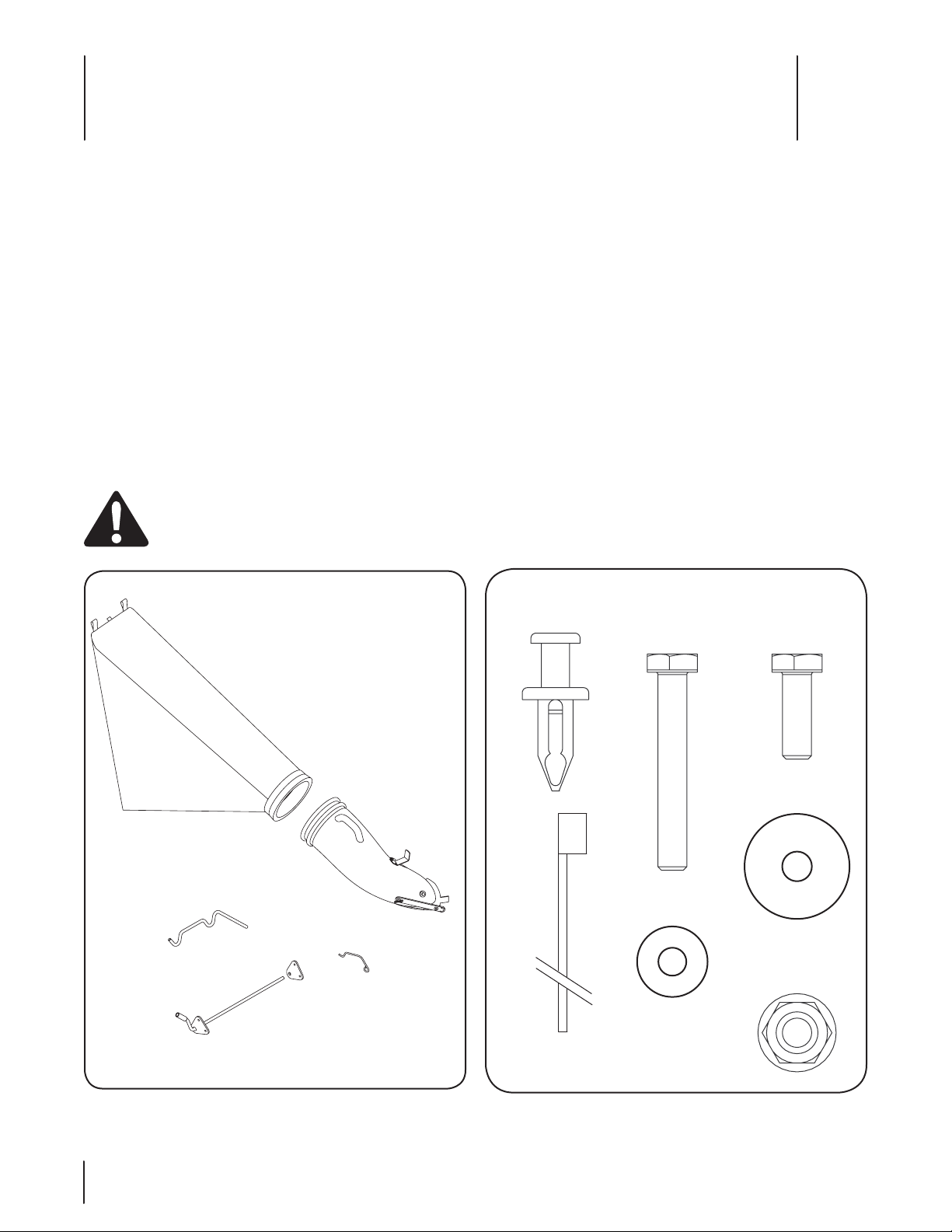
[A] - Grass bag
(764 -04052)
[J] - Latch
(747 -0 4670 )
[B] - Chute Assembly
(931- 04311)
[C] - Rod Assembly (647-04110-0637)
[D] - Rod Hanger
(747-04671)
[E] - Rod Bracket
(787-01569-0637)
[M] -Rivet (Qty. 1)
(728-0199)
[I] - Cable Tie (Qty. 1)
(726-0209)
[F] - Hex Cap Screw,
1/4-20 x 1.75” (Qty. 4)
(710-0136)
[G] - Flange Lock Nut,
1/4-20 (Qty. 1)
(712-04064)
[K] - Washer (Qty. 1)
(936-0176)
[H] - Washer (Qty. 4)
(936-0463)
[L] - Hex Cap Screw,
1/4-20 x .75” (Qty. 1)
(710-3015)
Assembly & Set-Up
3
Customer Support
If you have difficulty assembling this product or have any questions regarding the controls, operation, or maintenance of
this machine, you can seek help from the experts. Choose from the options below:
Visit us on the web at www.cubcadet.com◊
Call a Customer Support Representative at (800) 965-4CUB◊
Locate your nearest Cub Cadet Dealer at (877) 282-8684◊
Write us at Cub Cadet LLC • P.O. Box 361131 • Cleveland, OH • 44136-0019◊
Contents of Carton
Before installing this accessory, remove all parts from the carton. Carton contents, including items included within the hardware pack,
are shown in Figures 1 and 2. Part numbers are shown in parentheses and each item has been identified with a letter code in brackets,
for use when following the assembly instructions.
WARNING: Before installing this accessory, shut the engine off and allow it to cool. Disconnect the spark plug wire from
the spark plug and remove ignition key on electric start units. Refer to the mower’s Operator’s Manual for complete
safety instructions. Do not operate the mower without the entire grass collector in place. Stop the blade before emptying
the grass collector.
2
Figure 2Figure 1
Page 3
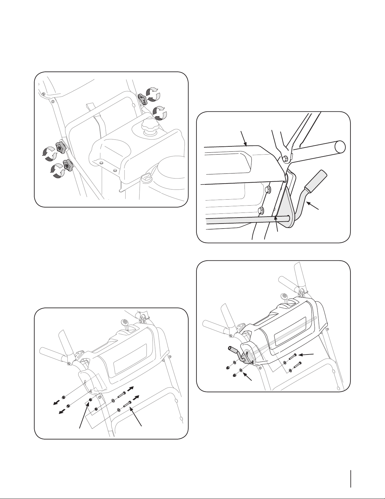
Installing the Right Side Bracket
Jam Nuts
Screws
Rod
Assembly [C]
Plastic Outer Panel
Metal Inner Panel
F
H
Shut off engine and disconnect the spark plug wire.1.
Loosen the four star knobs by turning the knobs 2.
counterclockwise five full rotations. See Fig. 3.
Figure 3
Installing the Right Bracket
Position the rod assembly [C] between the metal panel and 4.
the plastic panel cover while aligning holes in rod assembly
with holes in the panels and securing with the following
hardware. See Fig. 5 and Fig. 6.:
Two 1/4-20 x 1.75” screws [F]•
Two flat washers [H]•
Two flat washers retained from disassembly•
Two 1/4-20 cap lock nuts retained from disassembly•
Removing the Right Side Hardware
Remove the following from the right side of the upper 3.
handle. See Fig. 4.
Two 1/4-20 screws•
Two flat washers•
Two 1/4-20 cap lock nuts.•
Two Jam Nuts•
Discard the screws and jam nuts, but retain the two flat washers
and two cap lock nuts.
Figure 5
Figure 5
Figure 4
3se c t i O n 2 — as s e M b l y & se t -up
Page 4

Installing the Left Side Bracket
Jam Nuts
Screws
F
H
Remove the Left Side Hardware
Remove the following from the left side of the upper 1.
handle. See Fig. 6.
Two 1/4-20 screws•
Two flat washers•
Two 1/4-20 cap lock nuts.•
Two Jam Nuts•
Discard the screws and jam nuts, but retain the two flat washers
and two cap lock nuts.
Installing the Left Bracket
Position the rod assembly [C] between the metal panel and 2.
the plastic panel cover while aligning holes in rod assembly
with holes in the panels and securing with the following
hardware. See Fig. 7:
Two 1/4-20 x 1.75” screws [F]•
Two flat washers [H]•
Two flat washers retained from disassembly•
Two 1/4-20 cap lock nuts retained from disassembly•
Figure 6
Figure 7
Tightening the Handle Knobs
Tighten the four star knobs loosened in step 2.1.
4 se c t i O n 2— as s e M b l y & se t -up
Page 5

Assembling the Grass Bag
B
A
I
D
C
1
3
2
4
5
Place grass bag [A] over chute assembly [B]. See Fig. 8.1.
Use the cable tie [I] to secure bag to chute assembly by 2.
inserting the cable tie into hole in bag and pulling through.
Make sure cable is positioned so it ties bag around
indented groove (over flange) of chute. See Fig. 8. Pull
cable tight with pliers.
Attaching the Grass Bag Assembly
(newer Style Deck)
Lift the chute deflector on the deck back towards engine. 1.
See Fig. 9.
Place the bottom lip of the chute/grass bag assembly into 2.
the lip on the deck. See Fig. 9.
Place the tab of the chute/grass bag assembly into the 3.
bracket on the deck. See Fig. 9.
Lift chute/grass bag to position hole in chute over stud 4.
on the deck. The bracket on the chute will hold the chute
deflector into an upright position. See Fig. 9.
Pull the strap over the tab on the deck. See Fig. 9.5.
Figure 8
Attaching the Rod Hanger
Insert rod hanger [D] into the opening in the rod assembly 1.
[C]. See Fig 9.
Slide the tabs on the grass bag over the bag hanger rod. 2.
See Fig. 9.
Figure 9
Figure 8
5se c t i O n 2 — as s e M b l y & se t -up
Page 6

Attaching the Grass Bag Assembly
M
G
K
J
L
(Older Style Deck)
Remove the Chute Strap
Remove and discard the clevis pin, washer, hairpin clip and 1.
chute strap. See Fig. 10.
Figure 10
Install the Chute Latch
Pull the rivet’s plunger upward to unlock it and remove the 3.
rivet from the hole in the chute. See Fig. 12.
Figure 12
Secure the latch [J] to the chute with the hex screw [L], 4.
washer [K] and flange lock nut [G]. See Fig. 13.
Insert the rivet [M] into the hole in the chute and push the 2.
rivet’s plunger down to lock it in place. See Fig. 11.
Figure 11
Figure 13
6 se c t i O n 2— as s e M b l y & se t -up
Page 7

Attaching the Chute
1
3
2
4
5
Shut the engine off and disconnect spark plug. Pivot the 5.
chute deflector upward. See Fig. 14.
Secure the latch [J] to the side of the chute/grass bag 6.
assembly using the hardware provided.
Place the bottom lip of the chute/grass bag assembly into 7.
the lip on the deck. See Fig. 14.
Place the tab of the chute/grass bag assembly into the 8.
bracket on the deck. See Fig. 14.
Lift chute/grass bag to position hole in chute over stud 9.
on the deck. The bracket on the chute will hold the chute
deflector into an upright position. See Fig. 14.
Push the latch over the bracket on the deck. See Fig. 14.10.
Figure 14
Using the Grass Bag
WARNING: The operation of any lawn mower can
result in foreign objects being thrown into the eyes,
which can damage your eyes severely. Always wear
safety glasses while operating the mower, or while
performing any adjustments or repairs on it.
Empty the bag when 1. / full. To remove the grass bag, lift
discharge chute, lift chute/bag assembly from stud and
remove assembly from opening in deck. After the grass
bag assembly has been removed from the mower’s deck,
remove the grass bag assembly (along with the hanger rod)
from the right side support.
Unzip the bag and empty.2.
Zip the bag closed and reinstall entire assembly following 3.
“Attaching the Grass Bag Assembly” above. Check the grass
bag frequently for deterioration and wear. Replace worn
bag with new bag.
7se c t i O n 2 — as s e M b l y & se t -up
Page 8

CUB CADET LLC
MANUFACTURER’S LIMITED WARRANTY
FOR SEPARATELY SOLD ATTACHMENTS AND ACCESSORIES
IMPORTANT: To obtain warranty coverage owner may be required
to present an original proof of purchase and applicable maintenance
records to the servicing dealer. Please see the operator’s manual for
information on required maintenance and service intervals.
The limited warranty set forth below is given by Cub Cadet LLC with
respect to new merchandise purchased or leased and used in the United
States and/or its territories and possessions, and by MTD Products
Limited with respect to new merchandise purchased or leased and
used in Canada and/or its territories and possessions (either entity
respectively, “Cub Cadet”).
Cub Cadet warrants this product (excluding its Normal Wear Parts,
as described below) against defects in material and workmanship for
a period of two (2) years commencing on the date of original retail
purchase or lease and will, at its option, repair or replace, free of charge,
any part found to be defective in materials or workmanship.
Normal Wear Parts are warranted to be free from defects in material and
workmanship for a period of thirty (30) days from the date of original
purchase or lease. Normal wear parts include, but are not limited to
items such as: belts, blades, blade adapters, grass bags, rider deck
wheels, seats, and tires.
This limited warranty shall only apply if this product has been operated
and maintained in accordance with the Operator’s Manual furnished
with the product, and has not been subject to misuse, abuse, neglect,
accident, improper maintenance, alteration, vandalism, theft, fire, water,
or damage because of other peril or natural disaster. Damage resulting
from the installation or use of any part, accessory or attachment not
approved by Cub Cadet for use with the product(s) covered by this
manual will void your warranty as to any resulting damage. In addition,
Cub Cadet may deny warranty coverage if the hour meter, or any part
thereof, is altered, modified, disconnected or otherwise tampered with.
HOW TO OBTAIN SERVICE: Warranty service is available, WITH PROOF
OF PURCHASE AND APPLICABLE MAINTENANCE RECORDS, through
your local authorized service dealer. To locate the dealer in your area:
In the U.S. A. :
Check your Yellow Pages, or contact Cub Cadet LLC at P.O. Box 361131,
Cleveland, Ohio 44136-0019, call 1-877-282- 8684
or log on to our website at www.cubcadet.com.
In Canada :
Contact MTD Products Limited, Kitchener, ON N2G 4J1, call 1-800-6681238 or log on to our website at www.mtdcanada.com.
Without limiting the foregoing, this limited warranty does not provide
coverage in the following cases:
a. Routine maintenance items such as lubricants, filters, blade
sharpening, tune-ups, brake adjustments, clutch adjustments, deck
adjustments, and normal deterioration of the exterior finish due to
use or exposure.
b. Service completed by someone other than an authorized service
dealer.
c. Cub Cadet does not extend any warranty for products sold or
exported outside of the United States and /or Canada, and their
respective possessions and territories, except those sold through
Cub Cadet’s authorized channels of expor t distribution.
d. Replacement parts and\or accessories that are not genuine Cub
Cadet parts.
e. Transportation charges and service calls.
f. Commercial or Institutional Use.
There are no implied warranties, including without limitation any
implied warranty of merchantability or fitness for a particular
purpose. No warranties shall apply after the applicable period of
express written warranty above. No other express warranties beyond
those mentioned above, given by any person or entity, including a
dealer or retailer, with respect to any product, shall bind Cub Cadet.
The exclusive remedy is repair or replacement of the product as
set forth above. The terms of this warranty provide the sole and
exclusive remedy arising from the sale and/or lease of the products
covered hereby. Cub Cadet shall not be liable for any incidental or
consequential loss or damage including, without limitation, expenses
incurred for substitute or replacement lawn care services or for
rental expenses to temporarily replace a warranted product.
Some jurisdictions do not allow the exclusion or limitation of incidental
or consequential damages, or limitations on how long an implied
warranty lasts, so the above exclusions or limitations may not apply to
you.
In no event shall recovery of any kind be greater than the amount of the
purchase price of the product sold. Alteration of safet y features of the
product shall void this warranty. You assume the risk and liability for
loss, damage, or injury to you and your property and /or to others and
their property arising out of the misuse or inability to use the product.
This limited warranty shall not extend to anyone other than the original
purchaser or to the person for whom it was purchased as a gift.
HOW LOCAL LAWS RELATE TO THIS WARRANT Y: This limited warranty
gives you specific legal rights, and you may also have other rights that
vary in different jurisdictions.
Cub Cadet LLC, P.O. BOX 361131 CLEVELAND, OHIO 44136-0019, Phone: 1-877-282-8684
GDOC-100177 REV. A
MTD Products Limited, Kitchener, ON N2G 4J1, Phone: 1-800-668-1238
 Loading...