

Page 1
Safe Operation Practices • Set-Up • Operation • Maintenance • Service • Troubleshooting • Warranty
OperatOr’s Manual
Grass Collection System — Models 190 & 192
WARNING
READ AND FOLLOW ALL SAFETY RULES AND INSTRUCTIONS IN THIS MANUAL
BEFORE ATTEMPTING TO OPERATE THIS MACHINE.
FAILURE TO COMPLY WITH THESE INSTRUCTIONS MAY RESULT IN PERSONAL INJURY.
CUB CADET LLC, P.O. BOX 361131 CLEVELAND, OHIO 44136-0019
Printed In USA
Form No. 769-01136F
October 19, 2007
Page 2

To The Owner
Thank You
Thank you for purchasing a Grass Collector manufactured by
Cub Cadet LLC. It was carefully engineered to provide excellent
performance when properly operated and maintained.
Please read this entire manual prior to operating the equipment.
It instructs you how to safely and easily set up, operate and
maintain your machine. Please be sure that you, and any other
persons who will operate the machine, carefully follow the
recommended safety practices at all times. Failure to do so could
result in personal injury or property damage.
All information in this manual is relative to the most recent
product information available at the time of printing. Review
this manual frequently to familiarize yourself with the machine,
its features and operation. Please be aware that this Operator’s
Manual may cover a range of product specifications for various
models. Characteristics and features discussed and/or illustrated
in this manual may not be applicable to all models. Cub Cadet
LLC reserves the right to change product specifications, designs
and equipment without notice and without incurring obligation.
Table of Contents
Content of Carton.................................................... 3
Assembly & Operation ........................................... 4
This product has met the rigid safety standards of the Outdoor
Power Equipment Institute and an independent testing
laboratory. If you have any problems or questions concerning
the machine, phone your local Cub Cadet dealer or contact us
directly. Cub Cadet’s Customer Support telephone numbers,
website address and mailing address can be found on this page.
We want to ensure your complete satisfaction at all times.
Throughout this manual, all references to right and left side of the
machine are observed from the operating position.
Illustrated Parts List ................................................ 8
Warranty ..................................................Back Cover
Record Product Information
Before setting up and operating your new equipment, please
locate the model plate on the equipment and record the
information in the provided area to the right. You can locate the
model plate by looking at the rear of the cover. This information
will be necessary, should you seek technical support via our web
site, Customer Support Department, or with a local authorized
service dealer.
MOdel nuMber
serial nuMber
Customer Support
If you have difficulty assembling this product or have any questions regarding the controls, operation, or maintenance of
this machine, you can seek help from the experts. Choose from the options below:
Visit us on the web at www.cubcadet.com
◊
Call a Customer Support Representative at (800) 965-4CUB
◊
Locate your nearest Cub Cadet Dealer at (877) 282-8684
◊
Write us at Cub Cadet LLC • P.O. Box 361131 • Cleveland, OH • 44136-0019
◊
2
Page 3
Grass Bag
Assemblies
Hairpin
Clip
Clevis Pin
Blades
C
over
Assembly
Chute Tube
Support Tube
(attached to cover
assembly)
Bracket
Assembly
Discharge Chute
Assembly
Chute Stop Bracket
Carriage Bolt
Hex Lock Nut
Flange Lock Nut
Deck Baffle
Bell Washer
HH Cap Screw
NOTE: Model 190 Triple Bagger Kit is designed for use
on Fast Attach™ compatible tractors equipped with 50inch cutting deck only. This will NOT mount, nor operate
safely or properly on any other tractor regardless of the
tractor’s compatibility with similar accessories.
The instructions in this manual are divided into sections
that cover the installation of the 190-190 & 190-192 on
a 50” deck. Carefully read all sections and study the
illustrations to ensure proper installation and usage of
this attachment. Read and observe all WARNING and
CAUTION statements. They are included to provide for
the protection of the equipment installer and user, and to
ensure the prolonged service life of the equipment.
NOTE: References to LEFT and RIGHT indicate the left
and right sides of the tractor when facing forward in the
operator’s position. Reference to the FRONT indicates
the grille end; to the REAR, the rear end of the tractor.
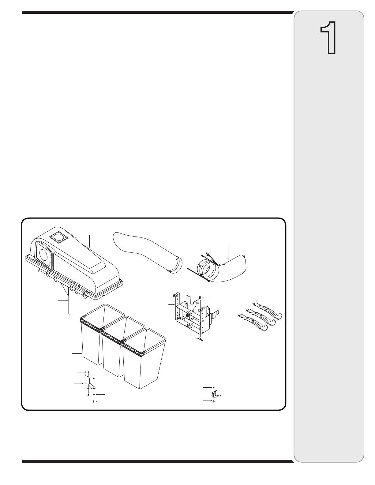
CONTENTS OF CARTON
Before beginning installation, remove all parts from the carton to make sure everything is present. Carton
contents are listed below and shown in Fig. 1-1.
1
Contents
of Carton
One Chute Tube
One Discharge Chute Assembly
Three Grass Bag Assemblies
One Support Tube
One Grass Catcher Cover Assembly
One Mounting Bracket (Shown Assembled)
Three Blades
Tube Extension
Chute Stop Bracket
Deck Deflector
Figure 1-1
3
Page 4
2
Assembly
And
Operation
NOTE:
References to left,
right, front and rear
of the tractor are
from the operator’s
position, unless
otherwise stated.
IMPORTANT:
There are two holes in
the clevis pin. Be sure
to insert the hairpin
clip in the upper hole
to properly secure the
bracket assembly to
the hitch plate.
Assembly & Operation
NOTE: References to left, right, front and rear of the
tractor are from the operator’s position, unless otherwise
stated.
• Before assembly, place the tractor on a firm, level
surface, disengage the PTO, stop the tractor engine
and set the parking brake.
• For convenience, pivot the seat forward and leave
it in that position until the grass collector is fully
mounted and assembled.
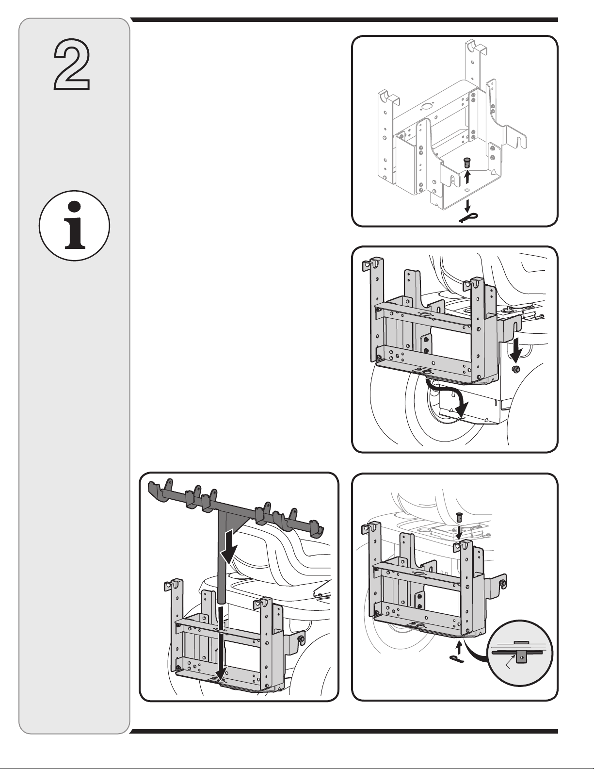
Mounting Bracket Assembly
• Remove the hairpin clip and clevis pin from the rear
of the mounting bracket assembly. See Figure 2-1.
• Position the hooked ends of the bracket assembly to
the outside of the hitch plate and over the shoulder
bolts. See Figure 2-2.
• Reinsert the clevis pin through the aligned holes
in both the bracket assembly and the hitch plate.
Secure with the hairpin clip. See Figure 2-3.
IMPORTANT: There are two holes in the clevis pin.
Be sure to insert the hairpin clip in the upper hole to
properly secure the bracket assembly to the hitch plate.
Attaching Grass Catcher Cover
and Grass Bags
• Place the grass catcher cover assembly’s support
tube in position on the rear of unit by sliding the
support tube down through the center hole in the
mounting bracket assembly. See Figure 2-4.
• Lift the grass catcher cover and attach the grass
bags using the slots shown in Figure 2-5. Close the
grass catcher cover.
NOTE: Cover not shown for clarity.
Figure 2-1
Figure 2-2
Figure 2-4
upper hole
Figure 2-3
4
Page 5

Hex Flange Nut
Spindle Assembly
Figure 2-5
Figure 2-6
Wood Block
Attaching Blades
WARNING: Always protect your hands
while servicing blades by wearing heavy
work gloves or using heavy rags.
NOTE: Three 2-in-1 (Discharge/Bag) blades are included
in the grass catcher kit. These will replace the 3-in-1
(Discharge/ Bag /Mulch) blades already installed on the
deck of the tractor. For better bagging performance, it is
recommended that you install these new 2-in-1 blades
included with this kit.
To Install Blades: Remove the cutting deck from beneath the tractor (refer to instructions for Deck Removal
in your tractor’s operator’s manual), then gently flip the
deck over to expose its underside.
• Place a block of wood between the center deck housing baffle and the cutting blade to act as a stabilizer.
See Fig. 2-6.
• Use a 1-1/8” wrench to remove the hex flange nut
that secures the blade to the outer blade spindle
assembly. See Fig. 2-6.
WARNING: The hex flange nut has a righthanded thread pattern. Do not attempt to
force the nut in an incorrect direction; it
may damage the nut and create a safety
hazard.
• Place a new blade on top of the outer blade spindle
so that side of the blade with part number faces the
ground when the mower is in the operating position.
• Secure with the hex flange nut removed earlier. Use a
torque wrench to tighten the hex flange nut between
70 to 90 foot-pounds.
• Replace blades from the other outer and center blade
spindles with the blades from the bagger kit.
NOTE: Save the three blades you just removed to use as
replacements or to reinstall on the blade spindles when
not using the bagger kit.
• Remount the cutting deck following instructions in the
owner’s manual of the tractor.
2
Assembly
And
Operation
WARNING
Always protect
your hands while
servicing blades
by wearing heavy
work gloves or using
heavy rags.
The hex flange nut
has a right-handed
thread pattern.
Do not attempt to
force the nut in an
incorrect direction;
it may damage the
nut and create a
safety hazard.
Deck Baffle
Hex Bolt
Hex Nut
Figure 2-7
Washer
Install Deck Baffle
• Remove two of the self-tapping deck screws on the
front right side of your deck. See Fig. 2-7.
• Install the front deck baffle using two hex nuts, belleville washers and hex bolts supplied in this bagger
kit.
NOTE:
Save the three
blades you just
removed to use as
replacements or to
reinstall on the blade
spindles when not
using the bagger kit.
5
Page 6

2
Assembly
And
Operation
Attaching Chute Stop Bracket
• Remove the carriage bolt and lock nut holding the
chute stop to the deck. See Inset A of Fig. 2-8. Save
the hardware.
• Replace with new chute stop bracket, from the bag
ger kit, at the same position on the deck. See Inset
B of Fig. 2-8. Secure with the hardware removed
earlier.
NOTE: An extra set of carriage bolt and lock nut have
been supplied in your accessory kit. You may replace
the old hardware for the chute stop bracket with these
new ones, or save for later use.
NOTE: This chute stop bracket may stay on the unit
even when the bagger is not being used.
-
A B
NOTE:
An extra set of
carriage bolt and lock
nut have been supplied
in your accessory kit.
You may replace the
old hardware for the
chute stop bracket with
these new ones, or
save for later use.
NOTE:
This chute stop
bracket may stay
on the unit even when
the bagger is not
being used.
Attaching Discharge Chute
• Raise the deck to its highest position.
• Raise the chute deflector (A in Fig. 2-9) on the deck
and hold it while you position the discharge chute
over the chute opening.
• Insert the hinge pin of the discharge chute into the
tube on the chute stop bracket. See B in Fig. 2-9.
• Rotate the chute around the deck so that its front
edge fits snugly into the deck opening. Lower the
chute deflector slowly(C in Fig. 2-9).
• Attach the longer of the three retainer straps on the
discharge chute to the retainer clip on the deck.
Refer to Fig. 2-10.
Attach long
strap here
Figure 2-8
A
Hinge Pin
Figure 2-9
C
B
Discharge Chute
Figure 2-10
6
Page 7

• Insert the curved end of chute tube into the hole in
the grass bag cover as shown in Fig. 2-11.
• Insert the lower end of the chute tube over the
discharge chute so that its two notches fit into the
two corresponding notches on the discharge chute.
See Fig. 2-12.
• Secure by placing the ends of the two short retainer
straps on the discharge chute over the pins on the
chute tube.
2
Assembly
And
Align notches
Figure 2-11
Bagger Usage
Your triple bagger kit is a valuable accessory to your
tractor. Optimize its performance by operating it correctly.
NOTE: Model 190 Triple Bagger Kit is designed for use
on Fast Attach™ compatible tractors equipped with 50inch cutting decks only. This will NOT mount, nor operate
safely or properly on any other tractor regardless of the
tractor’s compatibility with similar accessories.
When all grass bags are full, place the tractor on a
firm, level surface, disengage the PTO, turn the tractor
engine off and set the parking brake.
• Flip Seat up.
• Open the grass bag cover by lifting the cover up. Do
not remove the chute tube assembly from the tractor.
• Remove the grass bags by lifting these up and moving the bags away from the support tube assembly.
• Empty the grass clippings at a proper disposal site,
use the handle at the bottom of each grass bag.
Holding the bag firmly, empty the contents
• Replace grass bags, close lid, flip down seat, restart
your tractor and resume cutting your grass.
NOTE: Under normal usage, the grass bags are subject
to wear and tear. Check these bags periodically and
wash with water if dirty. Allow to air-dry; do not apply
heat.
Operation
NOTE:
Model 190 Triple
Bagger Kit is designed
for use on Fast Attach™
compatible tractors
equipped with 50-inch
cutting decks only.
This will NOT mount,
nor operate safely or
properly on any other
tractor regardless of the
tractor’s compatibility
with similar accessories.
Figure 2-12
7
Page 8

4
39
38
39
40
42
33
51
17
52
44
23
37
26
41
34
48
49
45
35
43
47
39
36
20
16
15
25
22
21
9
3
16
8
27
16
24
12
46
18
32
19
14
29
16
11
31
50
32
28
1
17
7
5
13
10
24
10
2
16
1
18
30
16
6
11
8
Page 9

Ref.
G
E
N
U
I
N
E
F
A
C
T
O
R
Y
P
A
R
T
S
No.
Part No. Description
1 17200A Catcher Support Bracket
2 17247 Support Tube Bracket
3 631-0221A Elbow Chute Assembly
4 664-04018 Grass Catcher Cover Assembly
(includes references 34-44)
5 683-0617A Chute Stop Bracket Assembly
6 689-00002 Grass Catcher Support Assembly
7 703-05783 Deflector, 50” Deck
8 710-0106 Hex Cap Screw, 1/4-20 x 1.25
9 710-0597 Hex Cap Screw, 1/4-20 x 1.00
10 710-0751 Hex Cap Screw, 1/4-20 x .62
11 710-3008 Hex Cap Screw, 5/16-18 x .75
12 710-3015 Hex Cap Screw, 1/4-20 x .75
13 710-3168 Carriage Bolt, 3 /8-16: 1.00
14 711-0309A Clevis Pin
15 711-04069 Grass Catcher Pin, 1/4-20
16 712-04064 Hex Flange Lock Nut, 1/4-20
17 712-04065 Hex Flange Lock Nut, 3 /8-16
18 712-3004A Hex Flange Lock Nut, 5/16-18
19 714-0117 Internal Cotter Pin, .148 x 3
20 723-04008A Chute Strap, 6.00 Long
21 723-0476 Retainer Strap Assembly
22 731-0926B Chute Tube
23 736-0253 Belleville Washer
24 736-0270 Bell Washer, .265 x .75 x .062
25 736-3092 Flat Washer .265 x 1.0 x .030
26 738-0380 Shoulder Screw, .50 x .27, 3 /8-16
Ref.
No.
Part No. Description
27 742-04056C Blade, 17.90Lg. Star Mnt, Bag.
28 783-0601 Catcher Support Bracket
29 783-0673B Catcher Support Bracket, RH
30 783-0764B Catcher Support Bracket, LH
31 783-0765 Catcher Support Bracket
32 783-1501 Catcher Spacer Bracket
33 764-0251 Grassbag Assembly
(Includes References 45-50)
34 17202B Bracket Mounting Screen
35 710-1652 Self-tap Screw, 1/4-20 x .625
36 720-04018 Screen
37 726-0233 Push Nut, .25 x .50
38 726-0479 Ratchet Clip
39 728-0123 Pop Rivet
40 731-04189 Grassbag Retainer Seal
41 731-0824A Plastic Plate
42 735-04020 Grassbag Hopper Seal
43 736-0400 Flat Washer, .194 x .62 x .063
44 749-0747 Hinge Bracket Assembly
45 17201A Bag Frame Hanger Bracket
46 710-0473 Screw, #10-24 x .5
47 710-0604A Self-tapping Screw, 5/16-18 x.625
48 712-0272 Hex Sems Nut, #10-24
49 749-0745A Grassbag Frame Tube
50 764-0251 Grass Catcher Bag
51 777D03361 Cub Cadet Logo (if equipped)
52 726-3040 Push Cap (if equipped)
3
Part List:
Rear Triple
Bagger
For parts and/or
accessories
please call
(800) 965-4CUB
9
Page 10

NOTES
Use this page to make notes and write down important information.
10
Page 11

NOTES
Use this page to make notes and write down important information.
11
Page 12

CUB CADET LLC
MANUFACTURER’S LIMITED WARRANTY
FOR SEPAR ATELY SOLD ATTACHMENTS AND ACCESSORIES
IMPORTANT: To obtain warranty coverage owner may be required
to present an original proof of purchase and applicable maintenance
records to the servicing dealer. Please see the operator’s manual for
information on required maintenance and service intervals.
The limited warranty set forth below is given by Cub Cadet LLC with
respect to new merchandise purchased or leased and used in the United
States and /or its territories and possessions, and by MTD Products
Limited with respect to new merchandise purchased or leased and
used in Canada and/or its territories and possessions (either entity
respectively, “Cub Cadet”).
Cub Cadet warrants this product (excluding its Normal Wear Parts,
as described below) against defects in material and workmanship for
a period of three (2) years commencing on the date of original retail
purchase or lease and will, at its option, repair or replace, free of charge,
any part found to be defective in materials or workmanship.
Normal Wear Parts are warranted to be free from defects in material and
workmanship for a period of thirty (30) days from the date of original
purchase or lease. Normal wear parts include, but are not limited to
items such as: belts, blades, blade adapters, grass bags, rider deck
wheels, seats, and tires.
This limited warranty shall only apply if this product has been operated
and maintained in accordance with the Operator’s Manual furnished
with the product, and has not been subject to misuse, abuse, neglect,
accident, improper maintenance, alteration, vandalism, theft, fire, water,
or damage because of other peril or natural disaster. Damage resulting
from the installation or use of any part, accessory or attachment not
approved by Cub Cadet for use with the product(s) covered by this
manual will void your warranty as to any resulting damage. In addition,
Cub Cadet may deny warranty coverage if the hour meter, or any part
thereof, is altered, modified, disconnected or otherwise tampered with.
HOW TO OBTAIN SERVICE: Warranty service is available, WITH PROOF
OF PURCHASE AND APPLICABLE MAINTENANCE RECORDS, through
your local authorized service dealer. To locate the dealer in your area:
In the U.S.A. :
Check your Yellow Pages, or contact Cub Cadet LLC at P.O. Box 361131,
Cleveland, Ohio 44136-0019, call 1-877-282- 8684
or log on to our website at www.cubcadet.com.
In Canada :
Contact MTD Products Limited, Kitchener, ON N2G 4J1, call 1-800-6681238 or log on to our website at www.mtdcanada.com.
Without limiting the foregoing, this limited warranty does not provide
coverage in the following cases:
a. Routine maintenance items such as lubricants, filters, blade
sharpening, tune-ups, brake adjustments, clutch adjustments, deck
adjustments, and normal deterioration of the exterior finish due to
use or exposure.
b. Service completed by someone other than an authorized service
dealer.
c. Cub Cadet does not extend any warranty for products sold or
exported outside of the United States and/or Canada, and their
respective possessions and territories, except those sold through
Cub Cadet’s authorized channels of export distribution.
d. Replacement parts and\or accessories that are not genuine Cub
Cadet parts.
e. Transportation charges and service calls.
f. Commercial or Institutional Use.
There are no implied warranties, including without limitation any
implied warranty of merchantability or fitness for a particular
purpose. No warranties shall apply after the applicable period of
express written warranty above. No other express warranties beyond
those mentioned above, given by any person or entity, including a
dealer or retailer, with respect to any product, shall bind Cub Cadet.
The exclusive remedy is repair or replacement of the product as
set forth above. The terms of this warranty provide the sole and
exclusive remedy arising from the sale and/or lease of the products
covered hereby. Cub Cadet shall not be liable for any incidental or
consequential loss or damage including, without limitation, expenses
incurred for substitute or replacement lawn care services or for
rental expenses to temporarily replace a warranted product.
Some jurisdictions do not allow the exclusion or limitation of incidental
or consequential damages, or limitations on how long an implied
warranty lasts, so the above exclusions or limitations may not apply to
you.
In no event shall recovery of any kind be greater than the amount of the
purchase price of the product sold. Alteration of safety features of the
product shall void this warranty. You assume the risk and liability for
loss, damage, or injury to you and your property and/or to others and
their property arising out of the misuse or inabilit y to use the product.
This limited warranty shall not ex tend to anyone other than the original
purchaser or to the person for whom it was purchased as a gift.
HOW LOCAL LAWS RELATE TO THIS WARRANTY: This limited warranty
gives you specific legal rights, and you may also have other rights that
vary in different jurisdictions.
Cub Cadet LLC, P.O. BOX 361131 CLEVELAND, OHIO 44136-0019, Phone: 1-877-282-8684
GDOC-100177 REV. A
MTD Products Limited, Kitchener, ON N2G 4J1, Phone: 1-800-668-1238
 Loading...