

Page 1

Safe Operation Practices • Contents of Carton • Set-Up & Assembly • Installation & Removal
Adjustments & Operation • Maintenance Warranty
Op e r a t O r ’s Ma n u a l
42” Snow Thrower Attachment — Model 190-341-100
WARNING
READ AND FOLLOW ALL SAFETY RULES AND INSTRUCTIONS IN THIS MANUAL
BEFORE ATTEMPTING TO OPERATE THIS MACHINE.
FAILURE TO COMPLY WITH THESE INSTRUCTIONS MAY RESULT IN PERSONAL INJURY.
CUB CADET LLC, P.O. BOX 361131 CLEVELAND, OHIO 44136-0019
Printed In USA
Form No. 769-06263
(July 23, 2010)
Page 2

To The Owner
Thank You
Thank you for purchasing a Cub Cadet snow thrower attachment.
It was carefully engineered to provide excellent performance
when properly operated and maintained.
Please read this entire manual prior to operating the equipment.
It instructs you how to safely and easily set up, operate and
maintain your machine. Please be sure that you, and any other
persons who will operate the machine, carefully follow the
recommended safety practices at all times. Failure to do so could
result in personal injury or property damage.
All information in this manual is relative to the most recent
product information available at the time of printing. Review
this manual frequently to familiarize yourself with the machine,
its features and operation. Please be aware that this Operator’s
Manual may cover a range of product specifications for various
models. Characteristics and features discussed and/or illustrated
in this manual may not be applicable to all models. We reserve
the right to change product specifications, designs and
equipment without notice and without incurring obligation.
Table of Contents
Safe Operation Practices ........................................ 3
Contents of Carton .................................................. 6
Set-Up & Assembly ................................................. 8
Installation & Removal ..........................................12
1
If you have any problems or questions concerning the machine,
phone your local Cub Cadet dealer or contact us directly. Cub
Cadet’s Customer Support telephone numbers, website address
and mailing address can be found on this page. We want to
ensure your complete satisfaction at all times.
IMPORTANT: This snow thrower attachment, for Cub Cadet
series 2000/2500 tractors, requires the 190-307 Weight Bracket
Kit and weights.
Throughout this manual, all references to right and left side of the
machine are observed from the operating position.
Adjustments & Operation ......................................15
Maintenance .........................................................18
Warranty ..................................................Back Cover
Record Product Information
Before setting up and operating your new equipment, please
locate the model plate on the equipment and record the
information in the provided area to the right. This information
will be necessary, should you seek technical support via our web
site or with your local Cub Cadet dealer.
MO d e l nu M b e r
se r i a l nu M b e r
Customer Support
If you have difficulty assembling this product or have any questions regarding the controls, operation, or maintenance of
this machine, you can seek help from the experts. Choose from the options below:
Visit us on the web at www.cubcadet.com◊
Locate your nearest Cub Cadet Dealer at (877) 282-8684◊
Write to Cub Cadet LLC • P.O. Box 361131 • Cleveland, OH • 44136-0019◊
2
Page 3

Important Safe Operation Practices
WARNING! This symbol points out important safety instructions which, if not followed,
could endanger the personal safety and/or property of yourself and others. Read and follow
all instructions in this manual before attempting to operate this machine. Failure to comply
with these instructions may result in personal injury.
When you see this symbol. HEED ITS WARNING!
CALIFORNIA PROPOSITION 65
WARNING! Engine Exhaust, some of its constituents, and certain vehicle components
contain or emit chemicals known to State of California to cause cancer and birth defects
or other reproductive harm.
DANGER: This machine was built to be operated according to the safe operation practices in
this manual. As with any type of power equipment, carelessness or error on the part of the
operator can result in serious injury. This machine is capable of amputating fingers, hands,
toes and feet and throwing foreign objects. Failure to observe the following safety
instructions could result in serious injury or death.
2
Training
Read, understand, and follow all instructions on the 1.
machine and in the manual(s) before attempting to
assemble and operate. Keep this manual in a safe place for
future and regular reference and for ordering replacement
parts.
Be familiar with all controls and their proper operation. 2.
Know how to stop the machine and disengage them
quick ly.
Never allow children under 14 years old to operate this 3.
machine. Children 14 years old and over should read and
understand the operation instructions and safety rules in
this manual and should be trained and supervised by a
parent.
Never allow adults to operate this machine without proper 4.
instruction.
Thrown objects can cause serious personal injury. Plan 5.
your snow throwing pattern to avoid discharge of material
toward roads, bystanders and the like.
Keep bystanders, pets and children at least 75 feet from the 6.
machine while it is in operation. Stop machine if anyone
enters the area.
Exercise caution while operating tractor with this 7.
attachment, especially when traveling in reverse.
Preparation
Thoroughly inspect the area where the equipment is to be 1.
used. Remove all door mats, newspapers, sleds, boards, wires
and other foreign objects which could be thrown by the
auger/impeller.
Always wear safety glasses or eye shields during operation and 2.
while performing an adjustment or repair to protect your eyes.
Thrown objects which ricochet can cause serious injury to the
eyes.
Do not operate without wearing adequate winter outer 3.
garments. Do not wear jewelry, long scarves or other loose
clothing which could become entangled in moving parts. Wear
footwear which will improve footing on slippery surfaces.
Adjust collector housing height to clear gravel or crushed rock 4.
surfaces.
Disengage all clutches and shift into neutral before starting the 5.
engine.
Never attempt to make any adjustments while engine is 6.
running, except where specifically recommended in the
operator’s manual(s).
Let tractor engine and attachment adjust to outdoor 7.
temperature before starting to clear snow.
3
Page 4

To avoid personal injury or property damage use extreme care 8.
in handling gasoline. Gasoline is extremely flammable and the
vapors are explosive. Serious personal injury can occur when
gasoline is spilled on yourself or your clothes which can ignite.
Wash your skin and change clothes immediately.
Use only an approved gasoline container.a.
Never fill containers inside a vehicle or on a truck or b.
trailer bed with a plastic liner. Always place containers on
the ground, away from your vehicle, before filling.
When practical, remove gas-powered equipment from c.
the truck or trailer and refuel it on the ground. If this is
not possible, then refuel such equipment on a trailer
with a portable container, rather than from a gasoline
dispenser nozzle.
Keep the nozzle in contact with the rim of the fuel d.
tank or container opening at all times, until refueling is
complete. Do not use a nozzle lock-open device.
Extinguish all cigarettes, cigars, pipes and other sources e.
of ignition.
Never fuel machine indoors. f.
Never remove gas cap or add fuel while the engine is hot g.
or running.
Allow engine to cool at least two minutes before h.
refueling.
Never over fill fuel tank. Fill tank to no more than ½ inch i.
below bottom of filler neck to provide space for fuel
expansion.
Replace gasoline cap and tighten securely.j.
If gasoline is spilled, wipe it off the engine and k.
equipment. Move machine to another area. Wait 5
minutes before starting the engine.
Never store the machine or fuel container inside where l.
there is an open flame, spark or pilot light (e.g. furnace,
water heater, space heater, clothes dryer etc.).
Allow machine to cool at least 5 minutes before storing.m.
Operation
Do not put hands or feet near rotating parts, in the auger/1.
impeller housing or discharge chute. Contact with the
rotating parts can amputate hands and feet.
Never operate with a missing or damaged discharge chute. 2.
Keep all safety devices in place and working.
When cleaning, repairing or inspecting the snow thrower, 3.
make certain the collector/impeller and all moving
parts have stopped. Disconnect the spark plug wire and
keep the wire away from the plug to prevent someone
from accidentally starting the machine. Do not run the
engine indoors, except when starting the engine and for
transporting the snow thrower in or out of the building.
Open the outside doors; exhaust fumes are dangerous.
Do not operate machine while under the influence of 4.
alcohol or drugs.
Muffler and engine become hot and can cause a burn. Do 5.
not touch.
Exercise extreme caution when operating on or crossing 6.
gravel surfaces. Stay alert for hidden hazards or traffic. Do
not carry passengers.
Exercise caution when changing direction and while 7.
operating on slopes.
Do not clear snow across the face of slopes; go up and 8.
down. Exercise extreme caution when operating on slopes.
Do not attempt to clear steep slopes.
Plan your snow throwing pattern to avoid discharge 9.
towards windows, walls, cars etc. To avoid property
damage or personal injury caused by a ricochet.
Never direct discharge at children, bystanders and pets or 10.
allow anyone in front of the machine.
Do not overload machine capacity by attempting to clear 11.
snow at too fast of a rate.
Never operate this machine without good visibility or light.12.
Disengage power to the auger/impeller when transporting 13.
or not in use.
Never operate machine at high transport speeds on 14.
slippery surfaces. Look down and behind and use care
when in reverse.
If the machine should start to vibrate abnormally, stop 15.
the engine, disengage the power take-off, lower the
attachment and set the parking brake. Inspect thoroughly
for damage. Repair any damage before starting and
operating.
After striking a foreign object, stop the engine (motor), 16.
remove the wire from the spark plug, thoroughly inspect
the snow thrower for any damage, and repair the damage
before restarting and operating the snow thrower.
Disengage the power take-off, lower attachment, set 17.
the parking brake and stop engine before you leave the
operating position. Wait until the auger/impeller comes to
a complete stop before unclogging the discharge chute,
making any adjustments, or inspections.
Do not carry passengers.18.
Use only attachments and accessories approved by the 19.
manufacturer (e.g. wheel weights, tire chains, cabs etc.).
If situations occur which are not covered in this manual, 20.
use care and good judgment. Contact your dealer or
telephone 1-800-800-7310 for assistance and the name of
your nearest servicing dealer.
4 se c t i O n 2 — iM p O r t a n t sa f e Op e r a t i O n pr a c t i c e s
Page 5

Clearing A Clogged Discharge Chute
Hand contact with the rotating impeller inside the discharge
chute is the most common cause of injury associated with snow
throwers. Never use your hand to clean out the discharge chute.
To clear the chute:
SHUT THE ENGINE OFF!1.
Wait 10 seconds to be sure the impeller blades have 2.
stopped rotating.
Always use a clean-out tool, not your hands3.
Maintenance And Storage
Never tamper with safety devices. Check their proper 1.
operation regularly.
Disengage power take-off, lower the attachment, set the 2.
parking brake, stop engine and remove key to prevent
unintended starting. Wait until the auger/impeller comes to a
complete stop before cleaning, repairing, or inspecting.
Check bolts, and screws for proper tightness at frequent 3.
intervals to keep the machine in safe working condition. Also,
visually inspect machine for any damage.
Do not change the engine governor setting or over-speed the 4.
engine. The governor controls the maximum safe operating
speed of the engine.
Snow thrower shave plates and skid shoes are subject to 5.
wear and damage. For your safety protection, frequently
check all components and replace with original equipment
manufacturer’s (O.E.M.) parts only. “Use of parts which do
not meet the original equipment specifications may lead to
improper performance and compromise safety!”
Check clutch controls periodically to verify they engage and 6.
disengage properly and adjust, if necessary. Refer to the PTO
and safety interlock system in your tractor’s operator’s manual
for instructions.
Maintain or replace safety and instruction labels, as necessary.7.
Observe proper disposal laws and regulations for gas, oil, etc. 8.
to protect the environment.
Prior to storing, run machine a few minutes to clear snow from 9.
machine and prevent freeze up of auger/impeller.
Never store the machine or fuel container inside where there 10 .
is an open flame, spark or pilot light such as a water heater,
furnace ,clothes dryer etc.
Always refer to the operator’s manual for proper instructions 11.
on off-season storage.
Safety Symbols
The safety symbols below may appear on this product. Read, understand, and follow all instructions on the machine before
attempting to assemble and operate.
Symbol Description
WARNING— ROTATING BLADES
Keep hands out of inlet and discharge openings while machine is running. There are rotating
blades inside
WARNING— ROTATING AUGER
Do not put hands or feet near rotating parts, in the auger/impeller housing or chute
assembly. Contact with the rotating parts can amputate hands and feet.
WARNING! Your Responsibility—Restrict the use of this power machine to persons who read, understand and
follow the warnings and instructions in this manual and on the machine.
SAVE THESE INSTRUCTIONS!
5se c t i O n 2 — iM p O r t a n t sa f e Op e r a t i O n pr a c t i c e s
Page 6
Contents of Carton
C
B
A
D
E
3
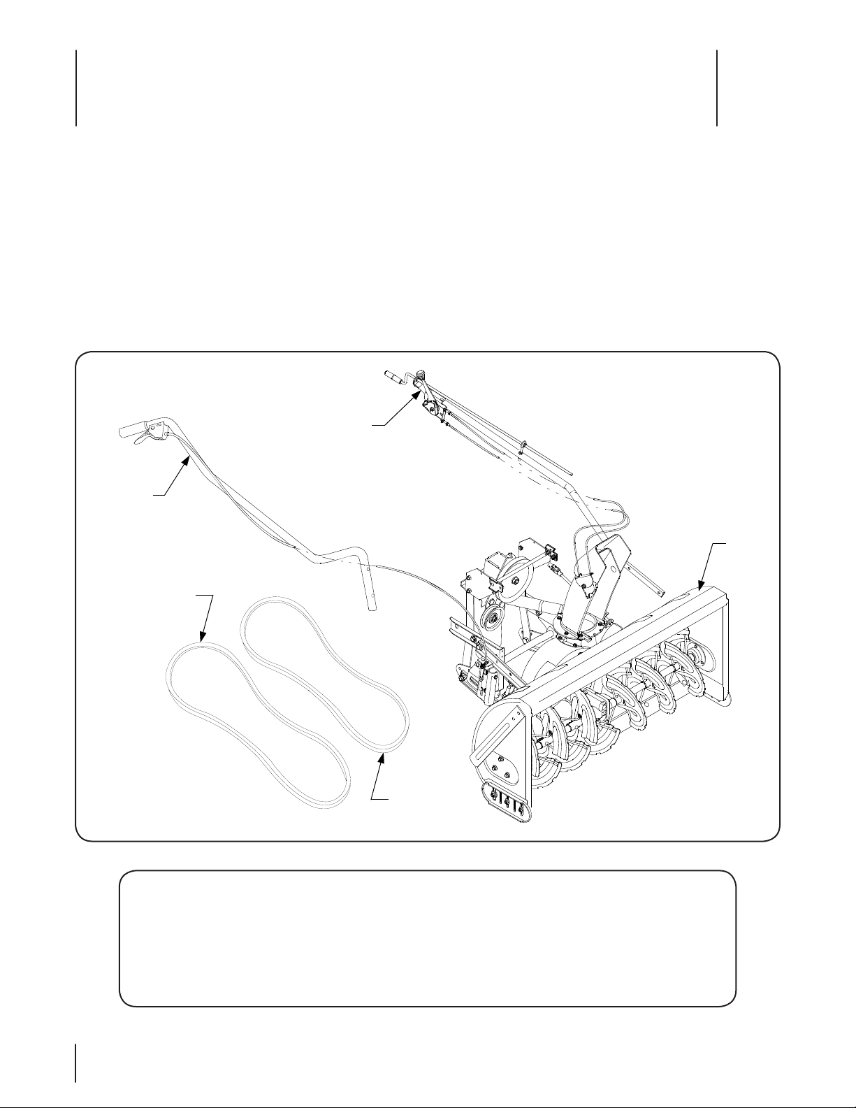
Select a firm level surface that is large enough to accommodate both the snow thrower assembly and the tractor. Remove the upper
crating material, and remove the hardware pack from the shipping crate. Carefully roll the snow thrower assembly rearward so that
it rests on its bottom; then carefully “walk” the snow thrower off the shipping pallet. When repositioning the snow thrower, use care
not to pinch or bind the chute crank support tube and/or lift handle (B and C, Figure 1). Cut the tie strap and remove the packaging
material from the chute crank support tube assembly (B) and position to the left side of the snow thrower assembly. Cut the tie strap
and remove the packaging material from the lift handle assembly (C) and position to the right side of the snow thrower.
Refer to Figures 3-1 and 3-2 to confirm that all parts are present and to acquaint yourself with the part descriptions. Throughout this
manual’s instructions, the parts shown in Figures 3-1 and 3-2 will be identified by name, followed by either their callout letter or part
number in parenthesis to aid in assembly and installation.
NOTE: Because different PTO clutch assemblies are used on the various Series 2000 tractor models, two PTO drive belts are provided
with the 341 Snow Thrower. If your tractor has a single cylinder engine, use the 754-0441 (shorter) V-belt. If your tractor has a twin
cylinder engine, use the 754-3075 (longer) V-belt.
REF. PART # DESCRIPTION QUANTITY
A N/A Snow Thrower / Discharge Chute Assembly 1
B N/A Chute Crank / Tilt and Support Assembly 1
C N/A Lift Handle / Latch Release Cable Assembly 1
D 754-0441 PTO Belt, Type A; 76.1 Lg- For Single Cylinder Engines 1
E 754-3075 PTO Belt, Type B; 78.3 Lg - For Twin Cylinder Engines 1
6
Figure 3-1
Page 7

1
2
3
4
5
6
7
8
9
10
12
13
14
15
16
11
17
13
Figure 3-2
REF. PART # DESCRIPTION QUANTITY
1 703-2737 Frame Mounting Bracket 2
2 714-3020 Internal Cotter Pin 2
3 711-3401 Rod, .5 Dia x 12.5 Lg. 1
4 714-0507 Cotter Pin, 3/32 x 3/4 Lg 1
5 738-04124 Pin, Shear, 1/4 x 1-1/2 Lg (2 Extra) 2
6 710-3180 Hex Cap Screw, 5/16-18 x 1.75 GR5 2
7 710-0528 Hex Cap Screw, 5/16-18 x 1.25 GR5 1
8 710-0216 Hex Cap Screw, 3/8-16 x .75 Lg GR5 2
9 710-0505 Hex Cap Screw, 7/16-14 x 1.0 GR5 2
10 710-0772 Hex Cap Screw, 5/16-24 x 2.0 GR5 1
11 725-0157 Cable Tie 7
12 714-04040 Pin, Bow-Tie Cotter (2 Extra) 2
13 712-04063 Hex Flange Lock Nut, 5/16-18 4
14 712-0431 Hex Flange Lock Nut, 3/8-16 2
15 736-0407 Bell Washer, .45 x 1.0 x .062 2
16 712-0411 Hex Insert Lock Nut, 5/16-24 1
17 710-0805 Hex Cap Screw, 5/16-18 x 1.5 GR5 1
7se c t i O n 3 — cO n t e n t s O f ca r t O n
Page 8
Assembly & Set-Up
CABLE TIE
SUBFRAME
ARMS
DRIVE
SHAFT
DRIVE SHAFT
HEX CAP
SCREW
HEX INSERT
LOCK NUT
SPROCKET BOX
CHUTE
CRANK
ROD
JOINT BLOCK
CRANK ROD
EYEBOLT
CHUTE CRANK
SUPPORT TUBE
HEX CAP SCREW
(1-1/2" LG.)
HEX CAP SCREW
(1-1/4" LG.)
LH UPPER
LINK
HEX FLANGE
INSERT LOCK NUT
COTTER PIN
JOINT
BLOCK
CHUTE CRANK
ASSEMBLY
CHUTE
CRANK
ROD
4
Snow Thrower Assembly Preparation
WARNING! Before beginning preparation of the
snow thrower assembly, select a firm and level
surface that is large enough to accommodate both
the snow thrower attachment and tractor. Engage
the tractor parking brake.
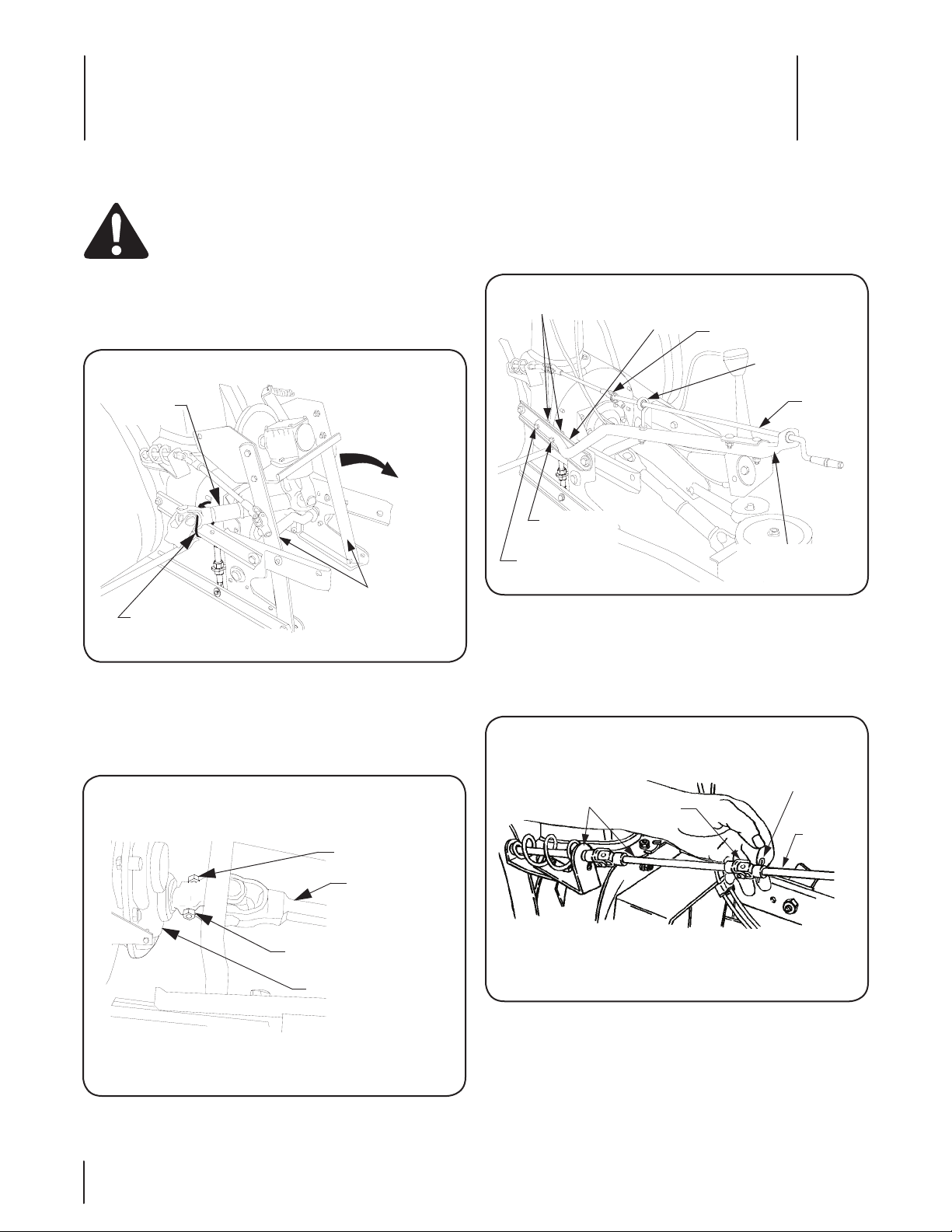
Cut the cable tie(s) securing the drive shaft to the snow 1.
thrower sub-frame and carefully unfold the sub-frame arms
See Figure 4-1.
Figure 4-1
Slide the front end of the drive shaft onto the input shaft of 2.
the sprocket box assembly on the rear of the snow thrower.
Align the holes and secure with hex cap screw (10, Fig.3-2)
and hex insert lock nut (16, Fig.3-2). See Figure 4-2.
Install the chute crank support tube (B, Fig.3-1) onto the LH 3.
upper link of the snow thrower (A, Fig.1) subframe using
the hex cap screw (7, Fig.3-2), hex cap screw (17, Fig.3-2) and
two hex flange lock nuts (13, Fig.3-2). Note: the longer hex
cap screw (17) must be installed in the rearward hole. Refer
to Figure 4-3.
Figure 4-3
After making sure the chute crank rod is routed through 4.
the eyebolt, insert the rod into the sleeve of the joint block
on the chute crank assembly. Align the holes and secure
the rod with the cotter pin (4, Fig.3-2). See Figures 4-3 and
4-4.
8
Figure 4-2
Figure 4-4
Route the tilt handle cables along the inside of the upper 5.
chute crank support tube and secure to the support tube
with two cable ties (11, Fig.3-2). See Figure 4-5. Cut excess
length from the cable ties.
Page 9

CABLE TIE
TILT HANDLE
CABLES
CHUTE CRANK
SUPPORT TUBE
CABLE TIES
TILT
HANDLE
CABLES
CHUTE CRANK
SUPPORT TUBE
LIFT SHAFT
LATCH
RELEASE
CABLE
LIFT BRKT.
SLOT
HEX CAP
SCREW
LIFT INDEX
ROD HOLE
CABLE ‘Z’
END FITTING
CONDUIT
FITTING
LIFT BRACKET
HEX FLANGE
LOCK NUT
LIFT
HANDLE
JAM NUT
LATCH
RELEASE
CABLE
TRIGGER
ASSEMBLY
LIFT HANDLE
CABLE
TIE
Figure 4-5
Route the tilt handle cables along the bend in the lower 6.
end of the chute crank support tube and secure to the
support tube with a cable tie (11, Fig. 3-2). See Figure 4-6.
Figure 4-6
Route the tilt handle cables across the top of the snow 7.
thrower lift shaft toward the right side of the snow thrower.
Loosely fasten the cables to the lift shaft with a cable tie
(11, Fig. 3-2). Do not fully tighten the cable tie. Refer to
Figure 4-6.
Insert the lower end of the lift handle assembly (C, Fig.1) 8.
into the lift bracket located on the right side of the snow
thrower subframe. See Figure 4-7.
NOTE: The latch release cable may, or may not, have been
Figure 4-7
connected to the lift index rod at the factory. If already
connected, skip to Step 12. If not connected, perform the
following steps 9-11 to connect the cable.
Insert the bottom of the cable ‘Z’ end fitting through the 9.
hole in the lift index rod. Refer to Figure 4-6.
If necessary, turn the jam nuts on the conduit fitting to 10.
create a space between the nuts. With a jam nut positioned
both above and below the lift bracket, slide the conduit
fitting fully into the slot of the lift bracket. Refer to Fig. 4-6.
Temporarily tighten the jam nuts against the upper and 11.
lower surfaces of the lift bracket.
Align the holes of the lift handle and lift bracket, and 12.
secure with the two hex cap screws (6, Fig.2) and hex
flange lock nuts (13, Fig.2). Refer to Figure 4-6.
Refer to Lift Latch Adjustment on Page 14 for instructions 13.
to adjust the cable.
Route the latch release cable along the lift handle and 14.
secure the cable to the handle using two tie straps (11,
Fig.3-2) as shown in Figure 4-8. Cut the excess from the tie
strap ends.
Figure 4-8
9se c t i O n 4 — as s e M b l y & se t -up
Page 10
Tractor Preparation
HEX TAP
SCREWS
FRONT BUMPER
TRACTOR
FRAME
HEX FLANGE
LOCK NUT
HEX CAP
SCREW
FRAME
MOUNTING
BRACKET
SIDE
FLANGES
TRACTOR
FRAME
HEX FLANGE
LOCK NUT
HEX CAP
SCREW
FRAME
MOUNTING
BRACKET
SIDE
FLANGES
This section describes the steps necessary to prepare the
appropriate tractor models for installation of the snow thrower
attachment. Some instructions apply only to specific production
model years. The production models referred to will be noted in
the heading for those instructions. Skip all instructions that do
not apply to your installation.
WARNING! If the tractor has been recently
operated, the muffler, exhaust pipe, and
surrounding areas will be HOT. Allow the tractor to
cool before beginning preparation.
NOTE: The mower deck and its front lift rod, or any other front
mounted attachment must be removed from the tractor.
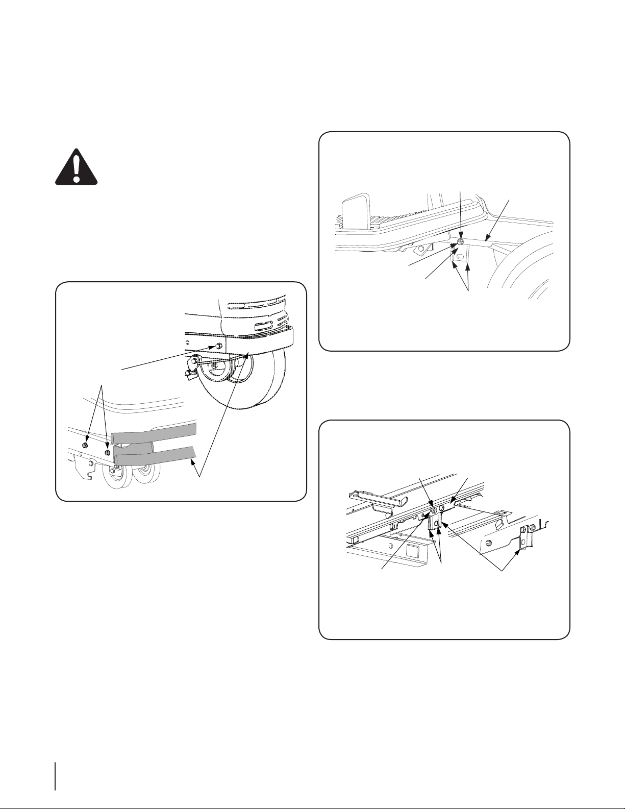
Remove the front bumper from the tractor frame by 1.
removing the hex tap screws securing the bumper in each
side of the tractor frame. Slide the bumper out of frame.
Store screws and bumper for later reassembly when the
snow thrower is removed. Refer to Figure 4-9.
Install the frame mounting bracket (1, Fig.3-2) onto each 3.
side of the tractor frame.
Series 2000 & 2500 Tractors Before Mfg. Date a.
J315. Looking beneath the front of both running
boards, locate the forward most open hole in each
side of the tractor frame. Refer to Figure 4-10.
Figure 4-9
Check for the presence of red reflector labels on the rear 2.
fender. If none are present, install the two reflector labels
provided with the snow thrower attachment. Thoroughly
clean the rear fender. Remove the backing from the
adhesive side of one reflector label. Position the label
horizontally and carefully affix to one side of the rear
fender of the tractor. Install the other reflector label to the
other side of the fender.
Figure 4-10
Series 2500 Tractors Mfg. Date K015 and After. b.
Looking beneath the front of both running boards,
locate the forward most open hole in each side of
the tractor frame. See Figure 4-11.
Figure 4-11
10 se c t i O n 4— as s e M b l y & se t -up
Page 11

Series 2500 Tractors, Mfg. Date B016 and After, c.
with 44 inch or larger mowing deck. A deck
up-stop bracket is installed on the right side of the
tractor frame, using the hole needed to install the
frame mounting bracket. From beneath the front of
the RH running board, remove the up-stop bracket
by removing the two hex screws and nuts. Reinstall
the front hex screw through the frame and steering
support bracket and secure with the hex nut. Store
the up-stop bracket and fasteners for reinstallation
when removing the snow thrower and installing the
mower deck.
Position the mounting brackets with the side flanges d.
facing outward from the tractor frame. Secure with
the two hex cap screws (8, Fig.3-2) and hex flange
lock nuts (14, Fig.3-2). Insert the cap screws from
inside the tractor frame.
11se c t i O n 4 — as s e M b l y & se t -up
Page 12

Installation & Removal
SUBFRAME
ARM
REMOVE
FRONT
FASTENERS
LOOSEN
REAR
FASTENERS
GEARBOX
MOUNTING
BRACKET
GEARBOX MTG.
BRACKET TILTED
REARWARD
DRIVE SHAFT
HALVES
CHANNEL
BRACKETS
FRONT LIFT
SHAFT
LIFT HANDLE
FRAME
CHANNEL
Snow Thrower Installation
WARNING! Before installing the snow thrower
assembly onto the tractor, ensure the PTO switch
and ignition switch are in the OFF position, the
parking brake is locked, and that the exhaust system
and surrounding areas have adequately cooled.
NOTE: To ease insertion into the tractor frame channels, apply
a light coating of grease to the channel brackets of the snow
thrower hitch assembly ( Refer to Figure 5-3).
Position the snow thrower assembly directly in front of the 1.
tractor with the subframe assembly extending rearward.
NOTE: Because of lower ground clearance on tractors
equipped with 15” front tires and 20” rear tires, the gearbox
mounting bracket, as assembled on the snow thrower
subframe, may not clear the front axle of the tractor. Note
that steps 2, 3 and 6 apply only to these tractors.
Units with 15” front tires ONLY. Remove the front hex flange 2.
lock nuts and cap screws securing the gearbox mounting
bracket to the subframe arms. Loosen the rear fasteners.
See Figure 5-1.
5
Figure 5-2
Slide the snow thrower assembly rearward until the 4.
channel brackets of the hitch assembly engage the frame
channels of the tractor. See Figure 5-3.
12
Figure 5-1
Units with 15” front tires ONLY. Using care to avoid 3.
separating the rear half of the drive shaft from the front
half, tilt the gearbox mounting bracket rearward. See
Figure 5-2.
NOTE: Turning the tractor’s front tires fully to the left or
right will slightly raise the front axle of the tractor and
provide more ground clearance.
Figure 5-3
Page 13

While manipulating the lift handle to keep the channel 5.
BELL WASHER
HEX CAP
SCREW
CHANNEL BRACKETS
FULLY INSERTED
SUBFRAME ARM
GEARBOX
MOUNTING
BRACKEY
REINSTALL
FRONT FASTENERS
TIGHTEN REAR
FASTENERS
FRONT IDLER PULLEYS
PTO CLUTCH
PTO BELT
PTO BELT
V-PULLEY
brackets parallel to the tractor frame, lift upward on
the front lift shaft and slide the snow thrower assembly
rearward until the channel brackets are fully inserted into
the frame channels. Secure the assembly to both sides of
the frame using the hex cap screws (9, Fig. 3-2) and bell
washers (15, Fig. 3-2). See Figure 5-4.
NOTE: Use the 754-0441 (D, Fig. 3-1) PTO belt for single
cylinder engines ONLY. Use the 754-3075 (E , Fig. 3-1) belt
for twin cylinder engines ONLY.
Install the appropriate PTO belt (D or E) on the PTO clutch 8.
pulley on the front of the engine by passing the belt
upward inside the front of the tractor frame. Make certain
the narrow side of the PTO belt engages the groove of the
clutch pulley. See Figure 5-6.
Figure 5-4
Tractors with 15” front tires ONLY. 6. Align the gearbox
mounting bracket with the subframe arms and reinstall the
front hex cap screws and flange lock nuts. Tighten the rear
fasteners. See Figure 5-5.
Figure 5-5
IMPORTANT: Series 2500 Tractors Mfg. Date K015 and After.
To open the tractor hood, the snow thrower must be lowered to the
ground and the discharge chute rotated to the straight forward
position.
Raise the tractor hood. Refer to the tractor Operator’s 7.
Manual.
Figure 5-6
Twist the PTO belt 1/4 turn inward to engage the narrow 9.
sides of the belt in the grooves of the tractor’s two front
idler pulleys. Refer to Figure 5-6.
Routing the PTO belt rearward under the tractor frame, 10.
install the narrow side of the belt in the V-pulley on the
snow thrower gearbox. See Figure 5-7. Make certain there is
no more than a 1/4 inward twist in both runs of the belt.
Figure 5-7
13se c t i O n 5— in s t a l l a t i O n & re M O v a l
Page 14
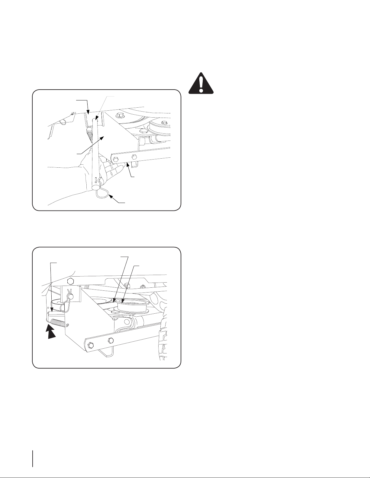
Install an internal cotter pin (2, Fig. 3-2) into one end of the 11.
INTERNAL
COTTER PIN
GEARBOX
MOUNTING
BRACKET
ROD
FRAME
MOUNTING
BRACKET
SUBFRAME
ARM
PTO BELT
FLAT IDLER
PULLEY
IDLER
BRACKET
PUSH
INWARD
rod (3, Fig. 3-2). Refer to Figure 5-8.
Lift the gearbox mounting bracket /sub-frame assembly up 12.
between the frame mounting brackets (1, Fig. 3-2) installed
earlier on the tractor. Align the holes and slide the rod (3,
Fig. 3-2) through the frame mounting brackets and the gear
box mounting bracket. Install the other internal cotter pin
(2, Fig. 3-2) into the other end of the rod. See Figure 5-8.
Figure 5-8
From the right side of the tractor, press the rearward end 13.
of the idler bracket inward to allow the flat backside of the
PTO belt in the flat idler pulley. See Figure 5-9.
Snow Thrower Removal
Drive the tractor with snow thrower assembly to a firm 1.
and level surface near the storage location. Disengage the
PTO, place the controls in neutral, and engage the parking
brake.
WARNING! The exhaust tube, muffler, and
surrounding areas are HOT. Allow the tractor to cool
before beginning removal of the snow thrower.
Grasp the lift handle (C) and squeeze the latch release 2.
trigger to lower the snow thrower to the ground (Refer to
Figure 6-5).
Press inward on the rear of the idler bracket to disengage 3.
the PTO belt from the flat idler pulley (Refer to Figure 5-9).
Remove the internal cotter pin from one end of the rod 4.
(3, Fig. 3-2). Support the gearbox mounting bracket and
withdraw the rod from the frame mounting brackets (Refer
to Figure 5-8). Lower the subframe to the ground.
Remove the PTO belt from the rear V-pulley on the snow 5.
thrower gearbox (Refer to Figure 5-7)
IMPORTANT: Series 2500 Tractors Mfg. Date K015 and After.
To open the tractor hood, the snow thrower must be lowered
to the ground and the discharge chute rotated to the straight
forward position.
Remove the PTO belt from the PTO clutch pulley and pass 6.
the belt downward through the bottom of the tractor
frame to remove the belt from the tractor (Refer to Figure
5-6).
Remove the hex cap screws and bell washers that secure 7.
the snow thrower channel brackets in both of the tractor
frame channels (Refer to Figure 5-4).
Units with 15” front tires ONLY. Remove the front hex flange 8.
lock nuts and cap screws securing the gearbox mounting
bracket to the subframe arms. Loosen the rear fasteners
(Refer to Figure 5-1).
Pull the snow thrower assembly forward to disengage the 9.
channel brackets from the tractor frame channels (Refer to
Figure 5-3).
NOTE: For off-season storage, keep all removed parts and
fasteners with the snow thrower to avoid their loss.
14 se c t i O n 5— in s t a l l a t i O n & re M O v a l
Figure 5-9
Page 15

Adjustments & Operation
AUGER
HOUSING
SKID SHOE
HEX NUTS AND
BELL WASHERS
CARRIAGE
BOLT
DRIFT
CUTTER
HEX INSERT
LOCK NUT
UPPER JAM NUT
LIFT LATCH
BRACKET
LOWER JAM NUT
RELEASE CABLE
LIFT INDEX ROD
LIFT
BRACKET
6
Adjustments
WARNING! If the snow thrower is to be used on
gravel surfaces, use extreme caution to avoid
picking up gravel with the shave plate or auger.
Loose gravel can damage the auger or housing, and
could be thrown at high speed by the impeller —
causing possible injury to bystanders or damage to
surrounding objects.
Skid Shoe Adjustment
The skid shoes are mounted on each side of the auger housing.
They determine the distance the shave plate is raised above the
plowing surface. The shave plate should be high for a gravel
driveway or other uneven surfaces and low for paved surfaces.
Adjust the skid shoes as follows:
Raise the snow thrower assembly slightly off the a.
ground and place a spacer under each end of the
shave plate.
Loosen the hex nuts and bell washers securing the b.
skid shoes to the housing. Refer to Figure 6-1.
Move the skid shoes up or down to the desired c.
position and securely tighten the hex nuts. Adjust
both skid shoes to the same height.
Turn the drift cutters to the up position and secure b.
with the carriage bolts and hex insert lock nuts as
shown in Figure 6-2.
Figure 6-2
Lift Latch Adjustment.
The lift index rod is operated by the trigger assembly on the lift
handle, through the latch release cable. The cable is adjustable to
assure proper engagement and release.
If the index rod does not latch securely, loosen the a.
upper jam nut and tighten the lower jam nut until
the rod fully seats in the latch slot of the lift latch
bracket. Refer to Figure 6-3.
If the release cable has excess slack and it is difficult b.
to disengage the rod from the latch slot, loosen the
lower jam nut and tighten the upper jam nut until
the excess slack is removed from the cable. Refer to
Figure 6-3.
Drift Cutters
Drift cutters on both sides of the auger housing can be adjusted
to the up position for a higher cut. Refer to Figure 6-2 and
proceed as follows:
Figure 6-1
Remove each drift cutter by removing the two hex a.
insert lock nuts and carriage bolts.
Figure 6-3
15
Page 16

Lift Link Adjustment
Lift Handle & Bracket Removed For Clarity
HEX NUT
HEX INSERT
LOCK NUT
LIFT EYE
BOLT
LIFT LINK
TRIGGER
ASSEMBLY
LIFT HANDLE
DISCHARGE CHUTE
UPPER SECTION
CHUTE
TILT HANDLE
CHUTE
CRANK
HANDLE
CHUTE CRANK ROD
DISCHARGE
CHUTE
The adjustable lift link assemblies at each end of the lift shaft
are adjusted at the factory and should not require readjustment.
However if the drive shaft makes contact with any part of the
tractor when the snow thrower is raised to the transport position,
the lift links should be adjusted as follows:
Raise the snow thrower to its fully raised position.a.
Loosen the hex insert lock nut at the top of one b.
adjustable eyebolt link. Refer to Figure 6-4.
Thread the hex nut beneath the lift link up the c.
eyebolt to lengthen the lift link assembly. Lengthen
the lift link assembly only as needed to eliminate the
drive shaft contact. Retighten the hex insert lock nut
after adjusting. See Figure 6-4.
Repeat the above procedures to adjust the lift link d.
assembly on the other side of the snow thrower to
the same length.
Figure 6-5
The discharge chute control crank is located on the left 3.
hand side of the snow thrower. The chute crank controls
the direction in which snow is thrown. The discharge radius
is 190 degrees. Turn the crank clockwise to discharge to
the left and counterclockwise to discharge to the right. See
Figure 6-6.
The chute tilt handle is also located on the left hand side 4.
of the snow thrower. The pivoting upper section of the
discharge chute pivots downward when the tilt handle is
pushed forward — decreasing the distance snow is thrown.
Pulling the handle backwards pivots the upper section
upward — increasing the distance snow is thrown. Refer to
Figure 6-6.
Figure 6-4
Controls
The snow thrower controls are conveniently located at the 1.
operator’s position on the tractor.
The lift handle is used to raise and lower the snow thrower. 2.
To raise the snow thrower, pull back and down on the lift
handle until the lift index rod fully engages the latch slot
of the lift latch bracket. To lower the snow thrower, push
slightly downward on the lift handle, then pull the trigger.
With the trigger pulled, lower the snow thrower slowly
until it contacts the ground. Refer to Figure 6-5.
16 se c t i O n 6— ad j u s t M e n t s & Op e r a t i O n
Figure 6-6
The front PTO switch on the tractor dash panel controls 5.
the snow throwing action. Engage the snow thrower auger
by pulling the PTO switch to the “Engaged” position. Push
the switch to the “Disengaged” position to stop the snow
throwing action.
Page 17

Operation
The following steps describe methods for safe and proper
operation of this snow thrower. Refer to “SAFE OPERATION
PRACTICES” on page 2 of this manual for additional safe
operating practices.
The snow thrower is capable of handling heavy snow 1.
conditions. Become fully familiar with all aspects of both
the tractor and snow thrower prior to its usage. DO NOT
remove any guards or covers while operating the tractor
and snow thrower.
WARNING! Whenever the snow thrower is installed
on the front of the tractor, use rear weights on the
tractor to counterbalance the weight of the snow
thrower and provide stability to the tractor. See “TO
THE OWNER” on page 5.
Before placing the snow thrower into operation:2.
Check all nuts and bolts for correct tightness. Be sure a.
that all parts are properly assembled.
Test all controls for proper operation.b.
Tractor lift handle•
PTO switch•
Discharge chute control crank assembly•
Discharge chute tilt control•
Inspect the tractor and snow thrower to make c.
certain both are in good operating condition.
Fill the tractor’s fuel tank outdoors. Avoid spilling d.
fuel onto the engine or any other source of heat or
combustion. Do not fill the tank while the engine is
running. Wipe up any spilled fuel before starting the
engine.
The auger speed is directly related to the engine speed. For 5.
optimal snow removal and discharge, maintain high engine
R.P.M. (full throttle). Control the tractor’s ground speed
using the forward control pedal of the tractor (refer to
tractor Operator’s Manual if necessary). It is recommended
that the tractor be operated at a slow ground speed for
safer handling and efficient snow removal.
Snow removal conditions vary greatly from light fluffy 6.
snowfall to wet heavy snow. Therefore, operating
instructions must be flexible to fit the conditions
encountered. The operator must adapt the tractor and
snow thrower to the depth of snow, wind direction,
temperature and surface conditions.
In deep, drifted or banked snow, it will be necessary to 7.
use full throttle and a slow ground speed. Drive the auger
into the snow, stop and allow the auger to clear the snow.
Repeat this method until a path is cleared. On the second
pass (and each succeeding pass), overlap the preceding
pass enough to allow the auger to handle the volume of
snow without having to stop the tractor.
In extremely deep snow, the snow thrower may be raised 8.
to the transport position, then slowly driven into the deep
snow to remove the top layers first. However, do not drive
the tractor into a snow bank where the snow has not been
cleared to the ground level. Stop the tractor’s forward
movement and allow the auger to clear the snow. Reverse
the tractor and lower the snow thrower to the ground to
clear the remaining snow. Working with repeated passes
into and out of drifts, even the deepest snow piles can be
cleared.
Special Precautions
WARNING! If the snow thrower becomes plugged
with snow or jammed due to hitting a foreign
object, disengage the snow thrower immediately
and stop the tractor engine.
WARNING! Never place your hand into the
discharge chute to remove plugged snow. Use a
wooden dowel rod, or similar object, to unclog the
chute. Never use your hand to remove any object
jamming the auger or impeller. Use an appropriate
tool (dowel rod, bar, etc.) to remove the obstruction.
WARNING! If the auger is jammed or bent from
hitting a foreign object, disengage the PTO, stop the
tractor engine, and remove the spark plug wire(s)
from the spark plug(s). Use the appropriate tool to
remove the foreign object from the auger and
inspect for damage. If damage is noted, repair or
replace damaged components prior to continuing
operation. Reconnect the spark plug wires and
resume operation.
Operating Tips
Whenever possible, discharge snow down wind.•
DO NOT attempt to clear ice or hard packed-frozen snow.•
Always overlap each pass slightly to assure complete snow •
removal.
A frozen or stuck auger or chute must be broken loose or •
thawed with care. When attempting to loosen a frozen or
jammed auger, shut off the tractor engine and disconnect
the spark plug wire(s). Never attempt to clear the snow
thrower at any time with the tractor engine running.
NOTE: When the snow thrower and tractor are not in use, lower
the snow thrower to the ground to relieve the weight from the
snow thrower sub-frame and the front tires.
WARNING! When making any adjustments,
disengage the PTO and turn the tractor engine off.
17se c t i O n 6— ad j u s t M e n t s & Op e r a t i O n
Page 18
Maintenance
SHEAR PIN
& BOW TIE
SHAVE
PLATE
SKID SHOE
AUGER
GEAR BOX
COTTER PIN
SKID
SHOE
CARRIAGE
BOLTS
BELL WASHER
& HEX NUT
During Seasonal Usage
This section describes maintenance procedures designed to keep
your snow thrower in good operating condition.
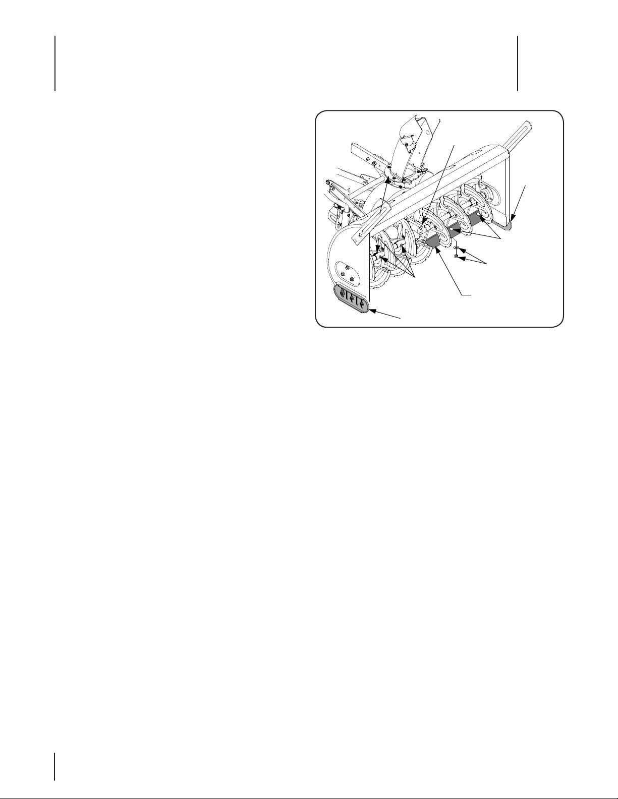
Shave Plate And Skid Shoes
The shave plate and skid shoes on the bottom of the snow
thrower housing are subject to wear. They should be periodically
checked for wear and replaced when necessary. Failure to do so
will result in damage to the housing. Refer to Figure 7-1.
Replace the shave plate as follows:
Remove the six hex nuts, bell washers, and carriage a.
bolts that secure the shave plate to the bottom of
the housing.
Remove the rear most hex nut, bell washer, flat b.
washer and carriage bolt securing the back end of
each skid shoe to the sides of the housing. Loosen
the four remaining hex nuts that secure the skid
shoes to the housing.
Slide the shave plate out of the off-set slot at the c.
bottom of the housing, and from between the skid
shoes and side panels of the housing.
With the mounting holes toward the back, slide the d.
new shave plate into position. Loosely install the six
carriage bolts, bell washers, and hex nuts fastening
the shave plate to the bottom of the housing.
Insert the carriage bolts through the rear of skid e.
shoes and the ends of the shave plate and the install
the flat washers, bell washers, and hex nuts removed
earlier.
Reposition the skid shoes and fully tighten the f.
fasteners securing the skid shoes to the housing.
Fully tighten the fasteners securing the shave plate.
The skid shoes are reversible for longer life. Remove the hex nuts,
flat washers, bell washers and carriage bolts fastening the skid
shoes to the housing. Turn the shoes over and/or reverse sides to
ensure even wear and extend their service life.
Augers
The augers are secured to the auger shaft with six shear 1.
pins and bow-tie cotter pins. Refer to Figure 7-1. If an auger
18
is suddenly jammed by a foreign object or ice chunk, the
pin is designed to shear — minimizing potential damage to
the gear box or sprocket box.
If the augers will not turn, check the pins to see if they 2.
have sheared. Two replacement shear pins (5, Fig. 3-2) and
bow-tie cotter pins (12, Fig. 3-2) have been provided with
the snow thrower. For future use, order part number 73804124A for replacement shear pins and 714-04040 for the
bow-tie cotter pins.
7
Figure 7-1
Lubrication
The auger gear box is lubricated with grease at the factory 1.
and is neither externally serviceable, nor requires checking.
If disassembled for any reason, lubricate with 2 ounces (by
weight) of Shell Alvania grease, part number 737-0168.
Before reassembling, remove all old sealant and apply
Loctite Ultra Grey (759-3746) sealant, or equivalent, to the
housing halves.
The sprocket box assembly is also neither externally 2.
serviceable, nor requires checking. If disassembled for any
reason, lubricate with 5.0 ounces (by weight) of Benalene
grease, part number 737-0300A. Before reassembling,
remove old sealant and apply Loctite Ultra Grey (759-3746)
sealant or equivalent.
The right angle gear box is not serviceable and should not 3.
be disassembled.
Apply penetrating oil to the cables of the chute tilt handle 4.
assembly at least once a season.
Apply a good grade of spray lubricant to the universal 5.
joints of the chute crank, and to the pivot of the chute tilt
handle at least once a season.
Lubricate the chute crank spiral gear with a multi-purpose 6.
automotive grease once a year.
Lubricate the telescoping square spindle of the drive shaft 7.
(rear half) using 251H EP grease or an equivalent No. 2
multi-purpose lithium grease once a year.
Lubricate the bearings at each end of the auger shaft with 8.
oil or spray lubricant at least once a season.
Although not necessary, it is advisable to remove the auger 9.
shear pins at least once a season and spray penetrating oil
between the auger tubes and auger shaft.
Page 19

Off-Season Storage
At the end of the snow season the following steps are
recommended:
Remove the snow thrower assembly from the tractor.1.
Wash off any salt deposits which may have dried on the 2.
snow thrower housing. Paint, or cover with a light coat of
oil, any exposed metal surfaces.
Lubricate bearings and pivot points with a good grade of 3.
spray lubricant.
Store the snow thrower in a dry place.4.
Additional Accessory Requirements
Weight Kit Model 307
WARNING! The weight kit, Model 307, must be
installed on the rear of the tractor whenever the
snow thrower attachment is installed on the front of
the tractor. The weight kit must be used with the
proper weights.
At all times that the snow thrower is installed on the front 1.
of the tractor, the weight kit must be installed on the rear
of the tractor. The weight kit counterbalances the weight of
the snow thrower and provides stability to the tractor.
Depending upon the prevailing conditions, a minimum 2.
of two suitcase weights and a maximum of four suitcase
weights must be used with the weight kit.
Refer to the weight kit Operator’s Manual for detailed 3.
instructions pertaining to the proper installation of the
weight kit onto the rear of the tractor.
Tire Chains
Tire chains are recommended when using the 42-inch snow
thrower attachment. Tire chains are available at your authorized
Cub Cadet dealer.
19se c t i O n 7— Ma i n t e n a n c e
Page 20

CUB CADET LLC
MANUFACTURER’S LIMITED WARRANTY FOR
SERIES 2500 TRACTORS
IMPORTANT: To obtain warranty coverage owner must present an
original proof of purchase and applicable maintenance records to the
servicing dealer. Please see the operator’s manual for information on
required maintenance and service intervals.
The limited warranty set forth below is given by Cub Cadet LLC with
respect to new merchandise purchased or leased and used in the United
States and/or its territories and possessions, and by MTD Products
Limited with respect to new merchandise purchased or leased and
used in Canada and /or its territories and possessions (either entity
respectively, “Cub Cadet”).
Cub Cadet warrants this product (excluding its Normal Wear Parts,
Batteries, Frame, Front Axle and Drive Shaft and Attachments as described
below) against defects in material and workmanship for a period of three
(3) years or one hundred fifty (150) operation hours, whichever comes
first, commencing on the date of original retail purchase or lease and
will, at its option, repair or replace, free of charge, any part found to be
defective in materials or workmanship.
Normal Wear Parts are warranted to be free from defects in material and
workmanship for a period of thirty (30) days from the date of original
purchase or lease. Normal wear parts include, but are not limited to
items such as: belts, blades, blade adapters, grass bags, rider deck
wheels, seats, and tires.
Batteries have a one-year prorated limited warranty against defects in
material and workmanship, with 100% replacement during the first three
months. After three months, the batter y replacement credit is based on
the months remaining in the twelve (12) month period dating back to the
original date of original sale or lease. Any replacement battery will be
warranted only for the remainder of the original warranty period.
Frame, Front Axle and Drive Shaft — Cub Cadet warrants the frame, front
cast iron pivot axle and drive shaft against defects in material and
workmanship for a period of five (5) years or 500 hours, whichever
occurs first, commencing on the date of original purchase or lease.
Attachments — Cub Cadet warrants attachments for this product against
defects in material and workmanship for a period of two (2) years,
commencing on the date of the attachment’s original purchase or
lease. Attachments include, but are not limited to items such as: grass
collectors and mulch kits.
This limited warranty shall only apply if this product has been operated
and maintained in accordance with the Operator’s Manual furnished
with the product, and has not been subject to misuse, abuse, neglect,
accident, improper maintenance, alteration, vandalism, theft, fire, water,
or damage because of other peril or natural disaster. Damage resulting
from the installation or use of any par t, accessor y or attachment not
approved by Cub Cadet for use with the product(s) covered by this
manual will void your warranty as to any resulting damage. In addition,
Cub Cadet may deny warranty coverage if the hour meter, or any part
thereof, is altered, modified, disconnected or otherwise tampered with.
HOW TO OBTAIN SERVICE: Warranty service is available, WITH PROOF
OF PURCHASE AND APPLICABLE MAINTENANCE RECORDS, through
your local authorized service dealer. To locate the dealer in your area:
In the U.S. A. :
Check your Yellow Pages, or contact Cub Cadet LLC at P.O. Box 361131,
Cleveland, Ohio 44136-0019, call 1-877-282- 8684
or log on to our website at www.cubcadet.com.
In Canada :
Contact MTD Products Limited, Kitchener, ON N2G 4J1, call 1-800-6681238 or log on to our website at www.mtdcanada.com.
Without limiting the foregoing, this limited warranty does not provide
coverage in the following cases:
a. Routine maintenance items such as lubricants, filters, blade
sharpening, tune-ups, brake adjustments, clutch adjustments, deck
adjustments, and normal deterioration of the exterior finish due to
use or exposure.
b. Service completed by someone other than an authorized service
dealer.
c. Cub Cadet does not extend any warranty for products sold or
exported outside of the United States and/or Canada, and their
respective possessions and territories, except those sold through
Cub Cadet’s authorized channels of export distribution.
d. Replacement parts and\or accessories that are not genuine Cub
Cadet parts.
e. Transportation charges and service calls.
There are no implied warranties, including without limitation any
implied warranty of merchantability or fitness for a particular
purpose. No warranties shall apply after the applicable period of
express written warranty above. No other express warranties beyond
those mentioned above, given by any person or entity, including a
dealer or retailer, with respect to any product, shall bind Cub Cadet.
The exclusive remedy is repair or replacement of the product as
set forth above. The terms of this warranty provide the sole and
exclusive remedy arising from the sale and/or lease of the products
covered hereby. Cub Cadet shall not be liable for any incidental or
consequential loss or damage including, without limitation, expenses
incurred for substitute or replacement lawn care services or for
rental expenses to temporarily replace a warranted product.
Some jurisdictions do not allow the exclusion or limitation of incidental
or consequential damages, or limitations on how long an implied
warranty lasts, so the above exclusions or limitations may not apply to
you.
In no event shall recovery of any kind be greater than the amount of the
purchase price of the product sold. Alteration of safety features of the
product shall void this warranty. You assume the risk and liability for
loss, damage, or injury to you and your property and/or to others and
their property arising out of the misuse or inability to use the product.
This limited warranty shall not extend to anyone other than the original
purchaser or to the person for whom it was purchased as a gift.
HOW LOCAL LAWS RELATE TO THIS WARRANTY: This limited warranty
gives you specific legal rights, and you may also have other rights that
vary in different jurisdictions.
Cub Cadet LLC, P.O. BOX 361131 CLEVELAND, OHIO 44136-0019, Phone: 1-877-282-8684
GDOC-100091 REV. A
MTD Products Limited, Kitchener, ON N2G 4J1, Phone: 1-800-668-1238
 Loading...