


USER MANUAL
Ctek Z Series Cellular Routers
Models Z4200 and Z4400
.
Ctek – Things That Move Data

26 October 2012
Table of Contents
TABLE OF CONTENTS I
TABLE OF FIGURES II
PREFACE 1
1 INTRODUCTION 1
1.1 Theory Of Operation 1
1.2 Features 1
2 CONNECTORS, LIGHTS, SWITCHES, AND JUMPERS 3
2.1 Switches 3
2.2 Lights 3
2.3 Connectors (see figures 3 and 4 below) 4
3 START UP 6
3.1 Power 6
3.2 Connecting the Antenna 6
3.3 Connecting to the Ethernet Port – Administrative Connection 6
4 ADMINISTRATION, CONFIGURATION AND STATUS 7
4.1 Getting Started 7
4.2 Interfaces 11
4.2.1 Configuring The Wireless Interface 11
4.2.2 Configuring The Ethernet Interace 15
4.2.1 The RS232/RS485 Interface 17
4.2.2 Configuring The Relay Input Interface 18
4.2.3 Configuring The Relay Output (Driver) Interface 19
4.3 Status 20
4.3.1 Wireless Status 20
4.3.2 Ethernet Status 26
4.4 Services 27
4.4.1 Password Administration 27
4.4.2 Routing and Forwarding Services 27
i

26 October 2012
Tunneling Services 30
4.4.3
4.4.4 Serial Communications Services 32
4.4.5 Admin Screen Services 40
4.4.6 Wireless Activation Services (Z4200 CDMA Only) 41
4.5 Options 46
4.5.1 Applications 46
4.5.2 Tools 46
4.5.3 SIM Editor (Z4400 HSPA Only) 46
4.5.4 AT Commands (Z4400 HSPA Only) 48
5 SPECIFICATIONS 49
6 CERTIFICATIONS 49
7 APPENDIX A – DISCRETE I/O ELECTRICAL DRAWINGS 50
Table of Figures
FIGURE 1 - LIGHTS AND SWITCHES .................................................................................................................................................. 3
FIGURE 2 - DB9 CONNECTOR .............................................................................................................................................................. 4
FIGURE 3 – Z4200S MODEL CONNECTORS ....................................................................................................................................... 5
FIGURE 4 – Z4200U MODEL CONNECTORS ...................................................................................................................................... 5
FIGURE 5 - WINDOWS CONFIGURATION ......................................................................................................................................... 7
FIGURE 6 - LOGIN SCREEN .................................................................................................................................................................. 8
FIGURE 7 - Z4200 TOP MENU ............................................................................................................................................................... 9
FIGURE 8 - Z4400 TOP MENU ............................................................................................................................................................. 10
FIGURE 9 - Z4200 (CDMA) WIRELESS INTERFACE........................................................................................................................ 11
FIGURE 10 - Z4200 NETWORK SELECT ............................................................................................................................................ 12
FIGURE 11 - Z4400 (HSPA) WIRELESS INTERFACE ....................................................................................................................... 13
FIGURE 12 - ETHERNET CONFIGURATION..................................................................................................................................... 15
FIGURE 13 - RS232/485 CONFIGURATION ....................................................................................................................................... 17
FIGURE 14 - RELAY INPUT CONFIGURATION ............................................................................................................................... 18
FIGURE 15 - RELAY OUTPUT CONFIGURATION ........................................................................................................................... 20
FIGURE 16 - WIRELESS STATUS (Z4200) ......................................................................................................................................... 21
FIGURE 17 - WIRELESS STATUS DETAILS Z4200 .......................................................................................................................... 23
FIGURE 18 - WIRELESS STATUS Z4400 ............................................................................................................................................ 25
FIGURE 19 - ETHERNET STATUS ...................................................................................................................................................... 26
FIGURE 20 = PASSWORD ADMINISTRATION ................................................................................................................................. 27
FIGURE 21 - ROUTING AND FORWARDING ................................................................................................................................... 28
FIGURE 22 - ADVERTISING ................................................................................................................................................................ 29
FIGURE 23 - GRE TUNNELING CONFIGURATION ......................................................................................................................... 30
FIGURE 24 - A GRE TUNNEL .............................................................................................................................................................. 31
FIGURE 25 - SERIAL COMMUNICATIONS MENU .......................................................................................................................... 32
FIGURE 26 - TCP PAD CONFIGURATION ......................................................................................................................................... 33
FIGURE 27 - UDP PAD CONFIGURATION ........................................................................................................................................ 38
FIGURE 28 - PPP CONFIGURATION .................................................................................................................................................. 39
FIGURE 29 - ADMIN SCREEN CONTROL ......................................................................................................................................... 40
FIGURE 30 - SPRINT ACTIVATION ................................................................................................................................................... 41
ii

26 October 2012
FIGURE 31 - VERIZON WIRELESS ACTIVATION ........................................................................................................................... 42
FIGURE 32 - ACTIVATION CONTROL .............................................................................................................................................. 42
FIGURE 33 - ACTIVATION LOG ......................................................................................................................................................... 43
FIGURE 34 - MANUAL ACTIVATION ................................................................................................................................................ 44
FIGURE 35 - SPRINT PRL UPDATE .................................................................................................................................................... 45
FIGURE 36 - USER DEFINED APPLICATIONS ................................................................................................................................. 46
FIGURE 37 - SIM MANAGEMENT ...................................................................................................................................................... 47
FIGURE 38 - AT COMMAND INTERFACE ........................................................................................................................................ 48
iii

26 October 2012
Preface
Welcome to the Ctek Z Series Cellular Router User’s Guide. This manual covers the Z4200 EVDO and the Z4400
UMTS/HSPA router. The User’s Guide will explain the basic operation of the router and take you through the necessary
settings to get your wireless application online. Additional information and applicable technical notices can be found at
www.ctekproducts.com.
Note that all administrative functions and screens on the two models are identical with the exception of the Wirel ess
Status and Wireless Interface screens, and the Z4200's Activation screen which is replaced on the Z4400 by a SIM Tools
menu item.
1 Introduction
Wireless routers provide application and network designers with a bridge between the world of IT infrastructure and the
evolving wireless M2M networks. With the Z Series the wireless transport is fully integrated into the product’s routing
fabric meaning that you can approach the setup and operation of this product much as with any other IP addressable
device. Wireless considerations are reduced to the absolute minimum necessary to register and make connections on a
network.
A number of optional controllers are available for use with the models covered in this manual including a micro amp
standby power controller, an analog/digital I/O controller, and a relay power controller. The operation of these device s is
covered in their specific user manual and in applicable TechNotes.
1.1 Theory Of Operation
The Z Series router is a complete IP router that routes traffic over LAN Ethernet (10/100baseT) connections. The wireless
features of the router simply extend the IP routing capabilities to include routing and network address translation (NAT)
over cellular wireless networks. As with most routers Ctek’s Z Series can be viewed as having a Local Area Network
(LAN) side and a Wide Area Network (WAN) side. Traffic originating at the router’s Ethernet or Serial port is considered
LAN traffic. The Wide Area Network connection is over the wireless network’s 1XRTT transport.
1.2 Features
This manual covers Ctek Z Series and contains the following feature and functions.
1) Ethernet
a. Static Addressing
b. Dynamic (DHCP) Server
c. Configurable DNS address
d. Configurable Gateway, Sub net mask, and Broadcast address
e. Port Forwarding
f. Service management
2) Wireless Interface
a. Enable/Disable WAN Interface
b. Enable/Disable inbound IP requests
c. DDNS Interoperability with Ctek's enhanced UDP interface
d. DDNS Interoperability with BIND or MS Server
e. Administration web server port address selection
f. Enhanced network activation (Z4200)
g. Home Network Selection
1

26 October 2012
3) RS232 (DB9 serial port)
a. Configurable Bit Rate
b. Configurable for Start/Stop Bits, Flow Control, and Parity
c. Local and remote Telnet Access
d. TCP/UDP Packet Assembly and Disassembly (PAD) function.
e. PPP Interface
4) RS485 Auxiliary Serial Port
a. Configurable Bit Rate
b. Configurable for Start/Stop Bits, Flow Control, and Parity
c. TCP/UDP Packet Assembly and Disassembly (PAD) function.
5) USB Host Connection
6) Relay Contact Closu re (detection and operation)
a. NO/NC detection
b. SMS or email cry out alarm
7) Relay Driver Output ( Maximum sink current 200ma @24V)
a. SMS Activation
b. Web Activation
8) General Administration
a. Modify User and Password
9) Status – Ethernet Status
a. Currently Assigned IP Address
b. Current MAC Address
10) Wireless Status – CDMA or HSPA/UMTS Status
a. ESN or IMSI
b. Network Assigned IP Address
c. Telephone Number (MIN) or MSISDN
d. Current Network Status Active/Inactive
e. Signal Level (RSSI)
2
26 October 2012
2 Connectors, Lights, Switches, and Jumpers
2.1 Switches
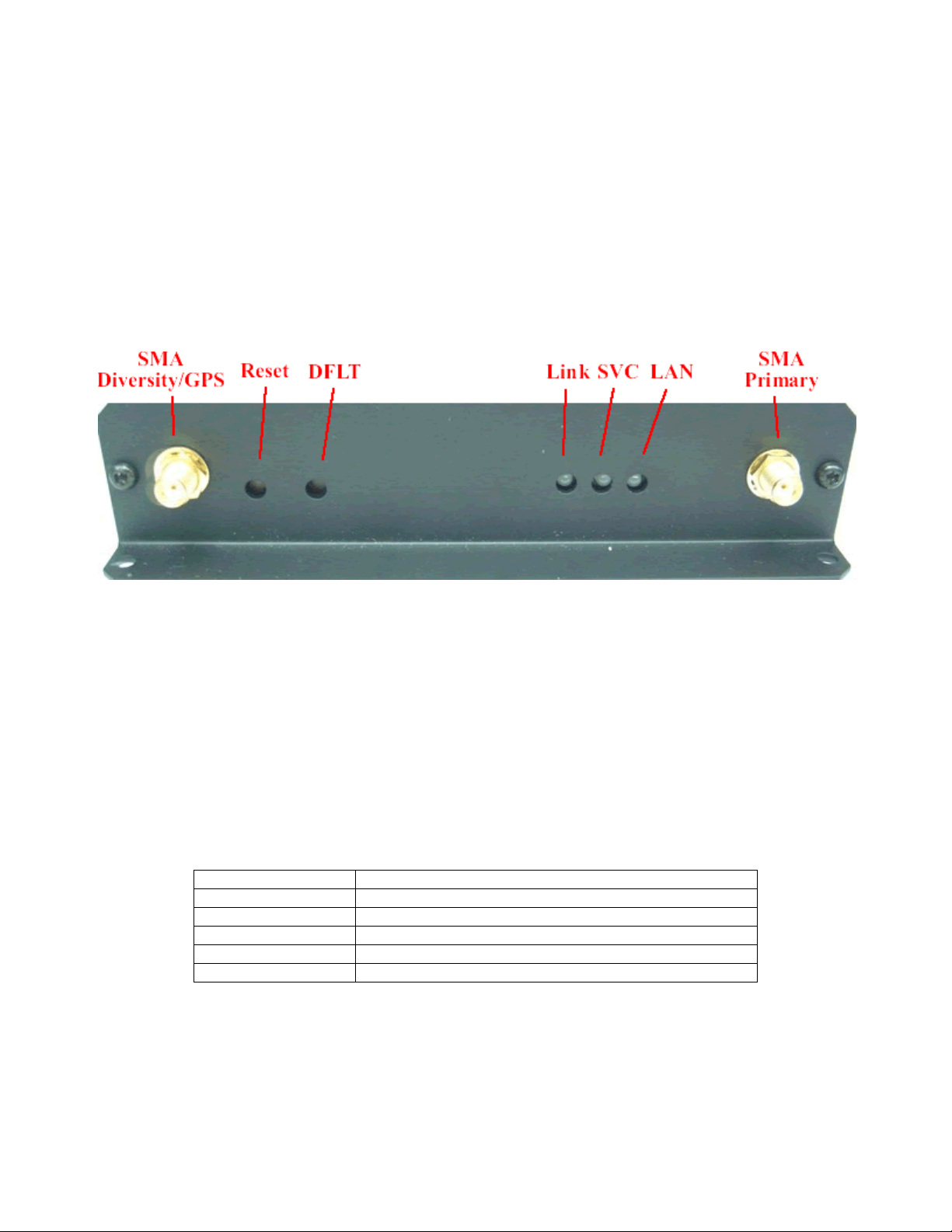
Referring to Figure 1, there are two switches on the front of the Z Series router. S1 (Reset) causes a hard reset of unit.
S2 (DFLT) is used to completely restore the firmware settings that were included when the product was shi pped from the
factory. To restore factory defaults, the unit must be running. You should wait a full two (2) minutes after booting or
powering on the unit before restoring factory defaults. After waiting two minutes press the Restore Defaults (inner) switch
and hold it down for 10 seconds. After 10 seconds, you will see both the green and yellow lights go off. At that time you
may either press the reset (outer) switch or cycle power on the unit.
Figure 1 - Lights and Switches
2.2 Lights
The Z Series router has indicators as shown in Figure 1.
LAN – The LAN light indicates that the Ethernet port is connected to an active Ethernet device.
The network status indicators LINK and SVC are interpreted as follows:
SVC – Multi-color (yellow/green). Indicates:
a) Power
b) RSSI
Display Definition
Off No Power
Yellow Blinking Power On – No Signal (RSSI)
Yellow Solid Power On – RSSI < -88
Green Solid Power On – RSSI >= -88
3
26 October 2012
Link - Multi-color (red/green). Indicates:
a) Status of IP connection
b) Type of transport (EV-DO or 1xRTT)
Display Definition
Off No Connection (IP address)
Green Connection established on 1xRTT or GPRS
Red Connection established on EV-DO or HSPA
2.3 Connectors (see figures 3 and 4 below)
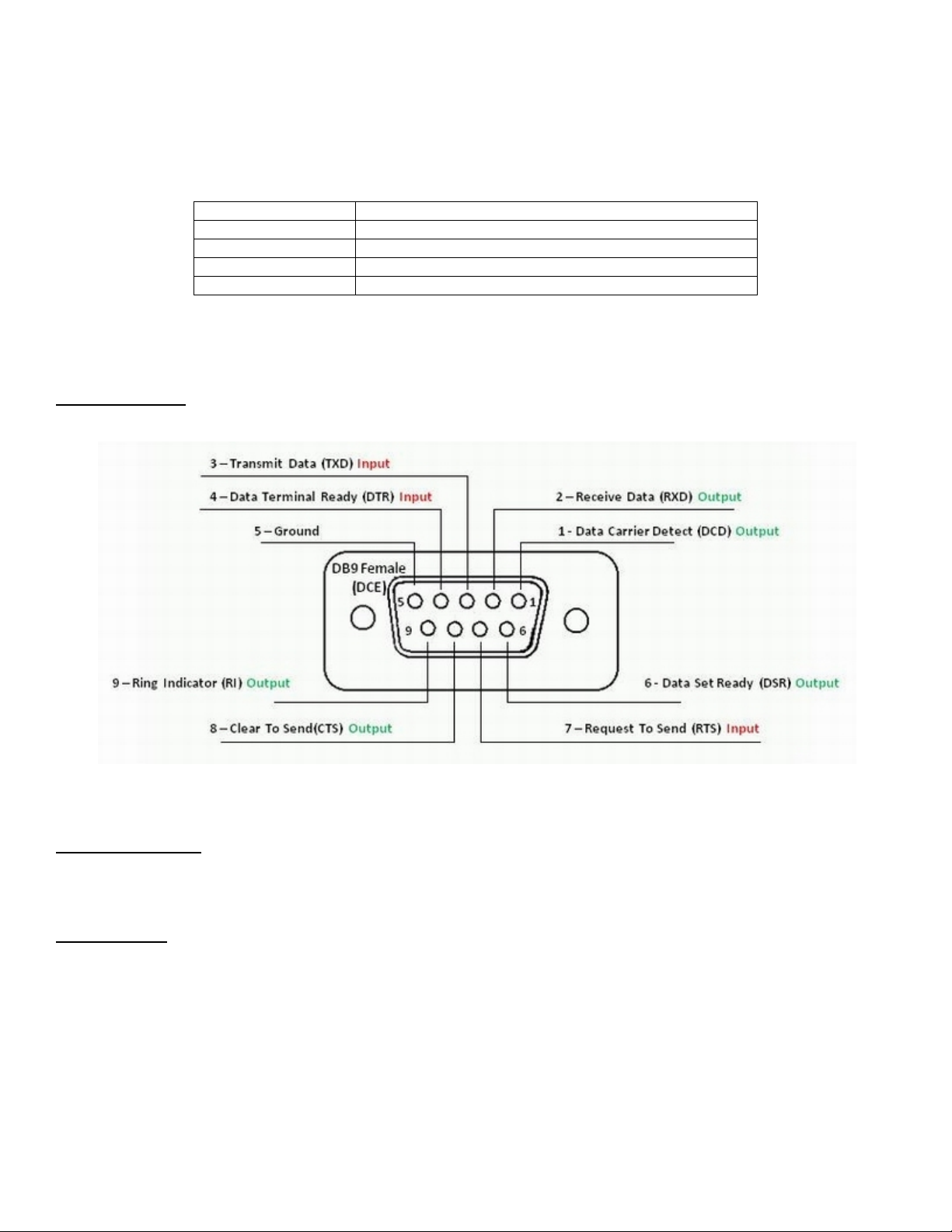
RS232 Connector – This connector is a standard RS232 DCE interface. A straight-through RS232 cabl e should be used.
The RS232 connector pin out diagram is shown below.
Figure 2 - DB9 Connector
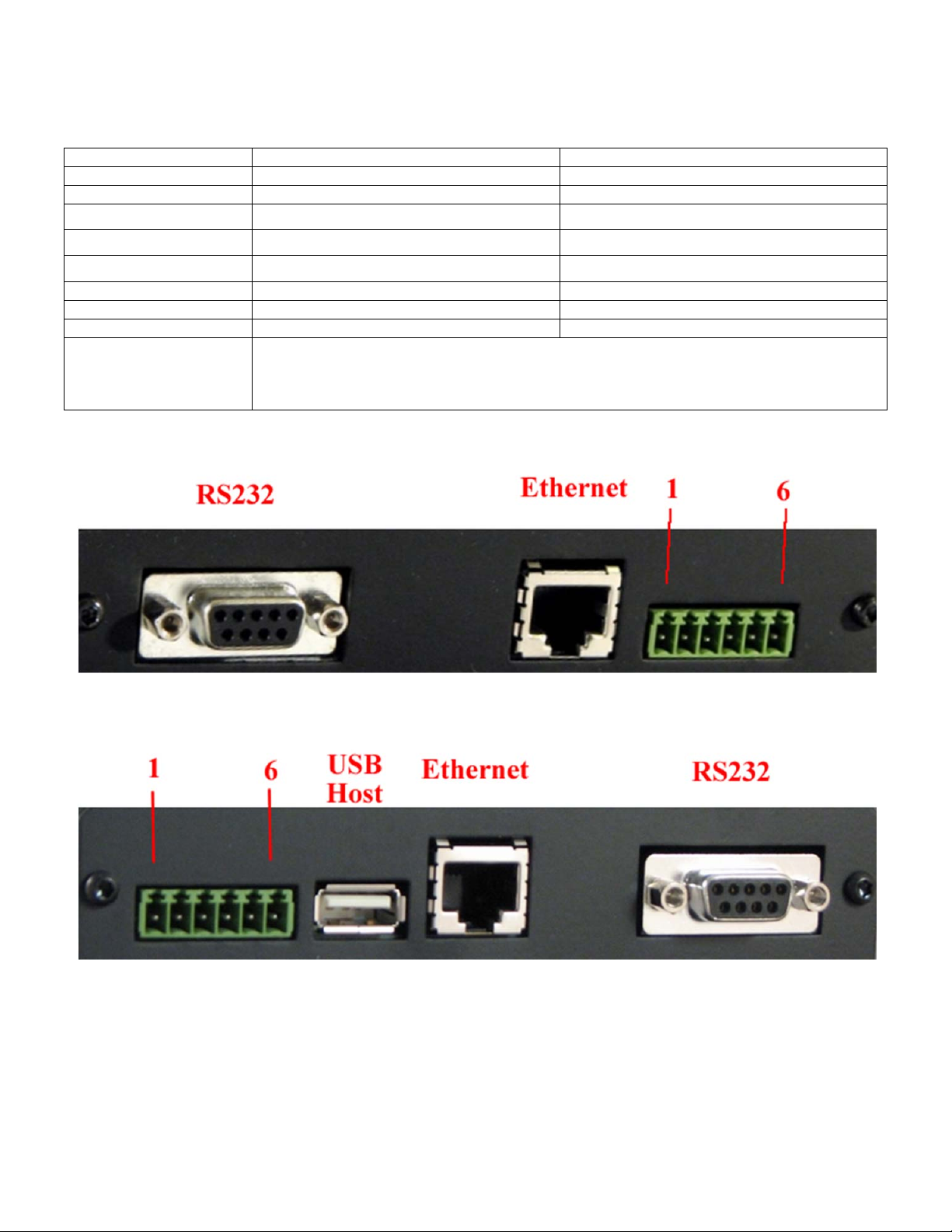
Ethernet Connector
The Ethernet connector on the Z Series is a standard RJ45 connector with auto polarity sensing and can be used with
either a standard Ethernet cable or a reverse (cross over) Ethernet cable.
Terminal Block
Connector J1 supports four separate functions, power, relay contact closure detection, relay driver output, and auxiliary
RS-485 serial port serial data. Contact closure pins 2 and 4 are shared with the auxiliary serial port. To option remove the
circuit board and locate 3-pin headers JP1 & JP2 behind the green connector. Facing the end of the board containing the
green connector JP1 and JP2 should have jumpers center to right to use the discrete I/O (Din, Dout), and JP1 and JP2
should have jumpers center to left to use the auxiliary RS-485 serial port. Auxiliary serial port parameters (baud, parity,
etc.) are set using the RS232/485 configuration screen. From the factory the unit ships with the auxiliary RS-485 serial
port enabled and configured as a master device.
.
4
26 October 2012
The J1 pin out configuration is as follows:
Terminal Block Pin JP1 & JP2 (internal) Center to Right JP1 & JP2 (internal) Center to Left
Pin 1 Din Src – Discrete Input Source
Pin 2
Pin 3
Pin 4
Din – Discrete Input (See Appendix A)
Dout Gnd – Discrete Output Ground
Dout - Discrete Output
3
TR+ of RS-485 auxiliary serial port1
TR- of RS-485 auxiliary serial port
Ground of RS-485 auxiliary serial port
Pin 5 Power supply Ground Power supply Ground
Pin 6 Power supply +12VDC Power supply +12VDC
Notes
Note 1
Note 2
Note 3
Connect a 120 ohm resistor across pins 2 --> 4 for multi-drop configurations
Available as a third wire ground for use in noisy environments
Discrete output is rated at 200ma @ 24 volts maximum sink current
1
2
Figure 3 – Z4200S model connectors
Figure 4 – Z4200U model connectors
5

26 October 2012
3 Start Up
Warning – You must connect antenna(s) to the SMA style antenna connectors on the router before turning it on.
Failure to do this could result in erratic start up behavior and could possibly damage the unit.
Note – Z Series routers ship from the factory with DHCP server enabled. The Default Gateway address for the
unit is 192.168.1.10. The address of the web based administration is also 192.168.1.10. After you have activated
your unit on the wireless network it WILL NOT have a DNS address, meaning that public Internet web access will
not work. To load DNS values go to the Ethernet Interface screen, select “Acquire From Wireless Network” and
press the update button. At this point the Primary and Secondary DNS addresses in the Ethernet Interface screen
will be populated with the DNS addresses provided by your wireless network. As a last step restart both the
router and the connected PC.
3.1 Power
Before starting connect the supplied 12VDC power adapter to the power connector de scribed in Section 2. The adapter
supplied with your router is suitable for use with 120VAC 60-hertz wall power. If you need a different power solutions
contact Ctek.
3.2 Connecting the Antenna
Antennas should be attached to the SMA style antenna connectors described in section 3. The antenna must be
connected before powering the unit on. ON the Z4200 the antenna connector to the right of the LAN LED is the primary
(transmit/receive) antenna and the connector to the left of the reset button is the secondary or diversity antenna.
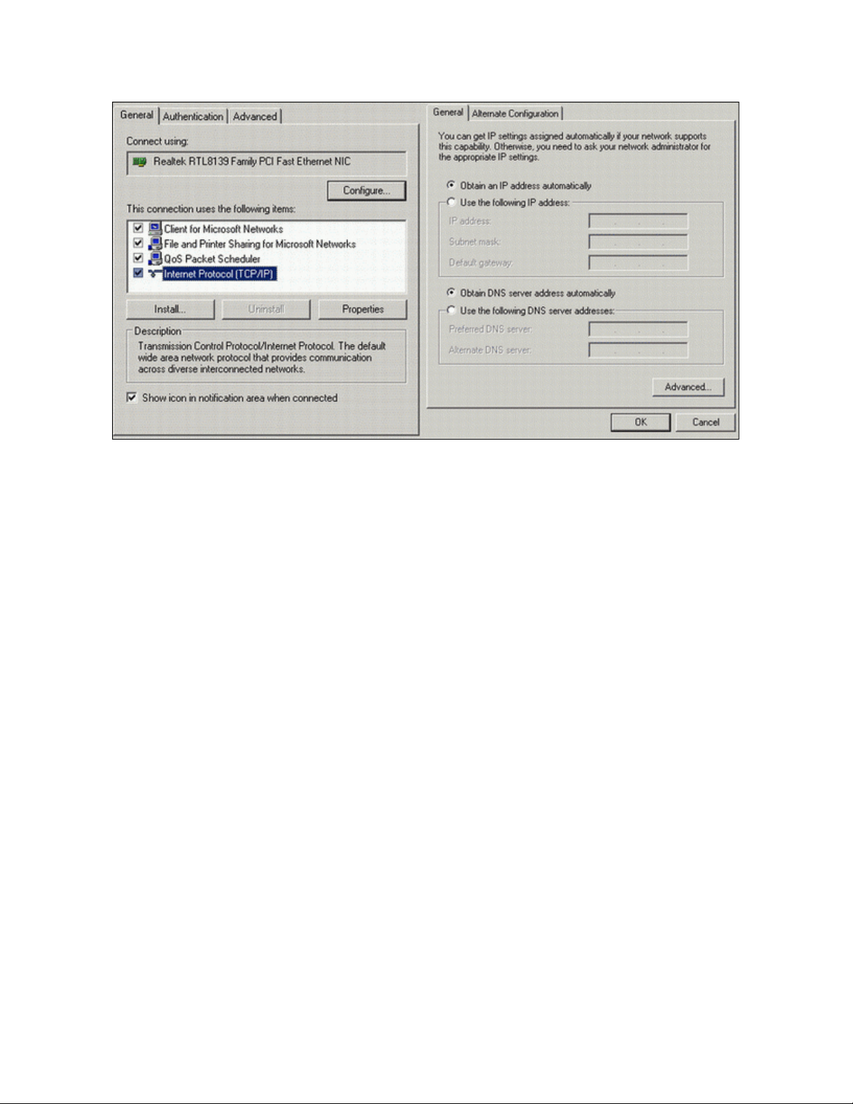
3.3 Connecting to the Ethernet Port – Administrative Connection
For a direct Ethernet connection between a PC connect to the Ethernet port using a standard or reverse Ethernet cable.
For initial configuration and administration with a PC or workstation Ctek recommends that the PC be set to obtain an IP
address and obtain a DNS address automatically. For Windows PCs make the following settings under the networking
control panel
6
26 October 2012
Figure 5 - Windows configuration
4 Administration, Configuration and Status
About Addressing – Devices connecting to cellular networks are assigned an IP address by the serving network.
Address assignment may either be static or the unit will be dynamically assigned an IP address, depending on
arrangements that you have made with your wireless network operator. Dynamically assigned IP address remain in effect
for a period of time assigned by the network operator, usually at most a small number of hours.
Ctek’s Z Series includes features that manage the temporal nature of dynamically assigned wireless IP addresses. Using
the Wireless Configuration screen you can configure your router to use a Dynamic DNS (DDNS) service. Ctek operates a
DDNS test bed that allows our customers to observe the performance and reliability of DDNS with their applications. For
large-scale commercial applications Ctek recommends that users configure their own DDNS, managed and maintained
with the customers ongoing IT operations. The Z Series may also be configured to operate with a standard DNS having
Dynamic DNS capabilities. Examples of this type of service would be
Server 2000 and up.
Even if you elect to use a static IP address a DDNS service will add value in two ways. First, when the networks static
addressing assignment fails there is a mandatory waiting period before the endpoint is allowe d to reinitiate the request for
a static address registration. During this period of time the network will dynamically assign addresses to the end point. A
DDNS service will make the end point network addressable (by name) during this period of time. Secondly, a name
service allows your end point to be known by a name that is independent of network addressing. Addressing a unit by
name may be easier for end users to remember and will, over a long period of time, reduce maintenance problems.
For detailed information see Ctek’s TechNote S001.
4.1 Getting Started
Once the PC has been set up properly and physically connected to the router you are ready to begin configuring the
router for your application. To access the Administration menu use any web browser pointed at http:// 192.168.1.10. A
login screen appears as shown below. The default User ID is “ctek” (without the quotes) and the default Password is also
“ctek”. Be sure to change the user ID and password and record your new selections.
Berkeley Internet Name Daemon (BIND) and Microsoft
7
26 October 2012
Figure 6 - Login Screen
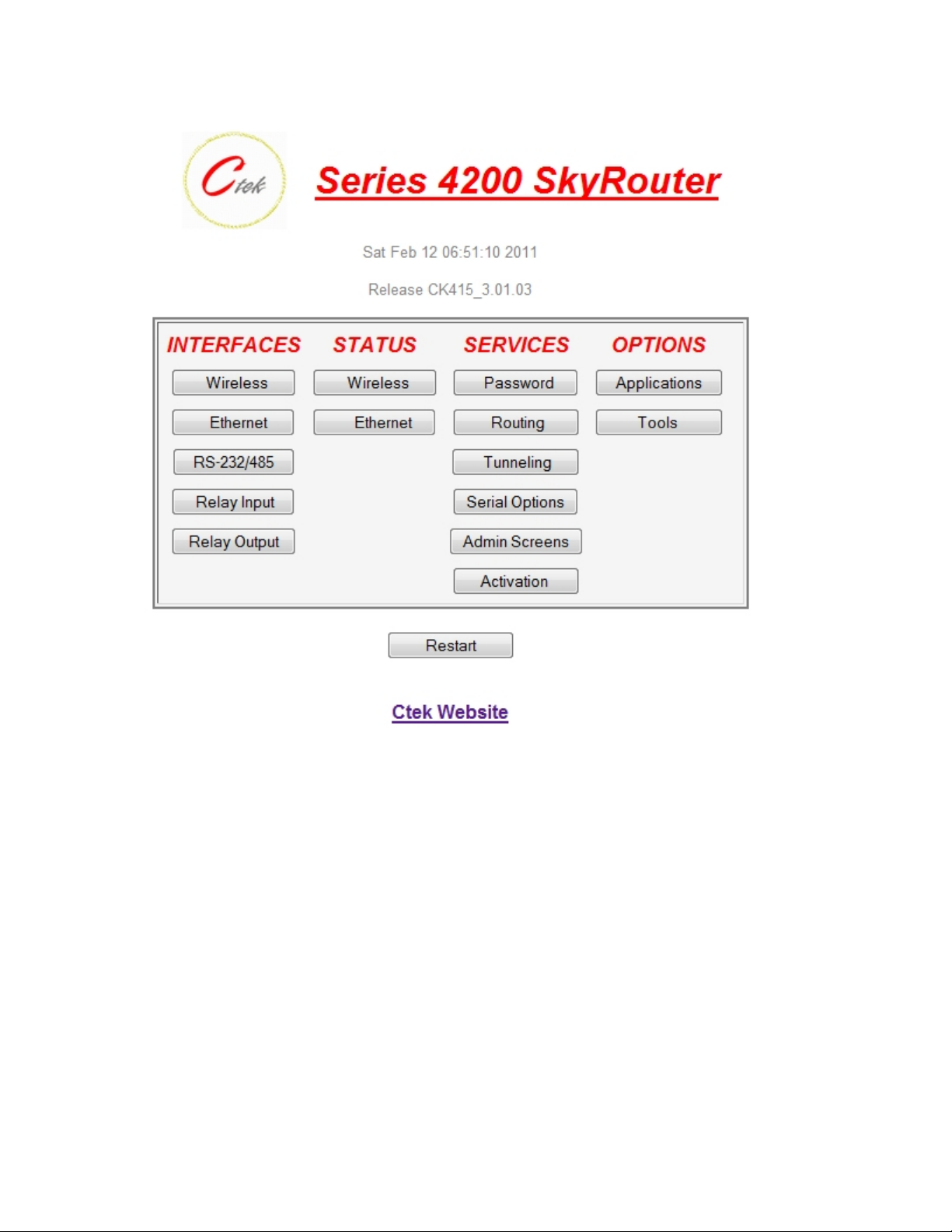
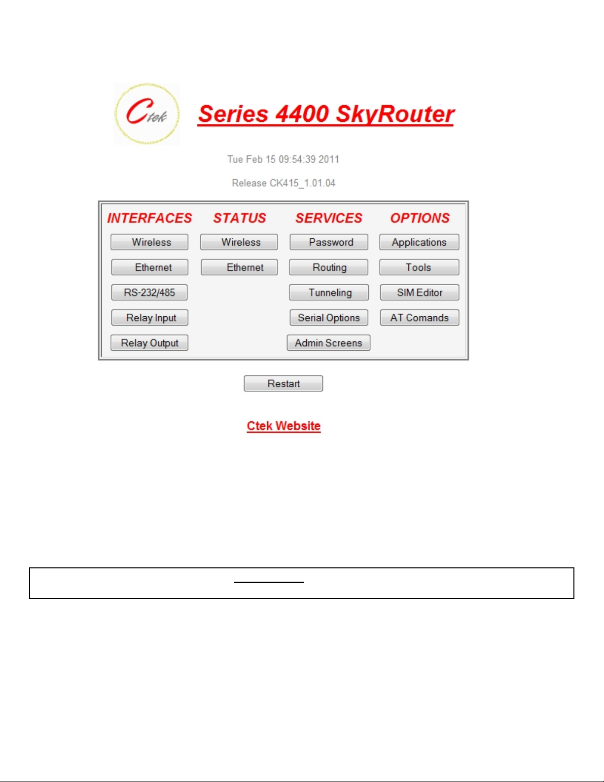
When you have completed the login process you will be presented with the top-level administration menu. Both the Z4200
and Z4400 top level menus are shown below.
8
26 October 2012
Figure 7 - Z4200 Top Menu
9
26 October 2012
Figure 8 - Z4400 Top Menu
Note that the administration menu is divided into four sections. The Interfaces section deals with physical connectivity,
managing the connection and subtended devices. Status screens are provided for the wireless and Ethernet interfaces.
Services are applications that are within the router core to modify the behavior of a specific interface or to change system
wide parameters within the router core. Under the Options category users can find any optional or custom applications
and tools provided to maintain the router.
Important Note – The Restart button must always be used to apply any changes made on specific
Interface or Service screens.
10
26 October 2012
4.2 Interfaces
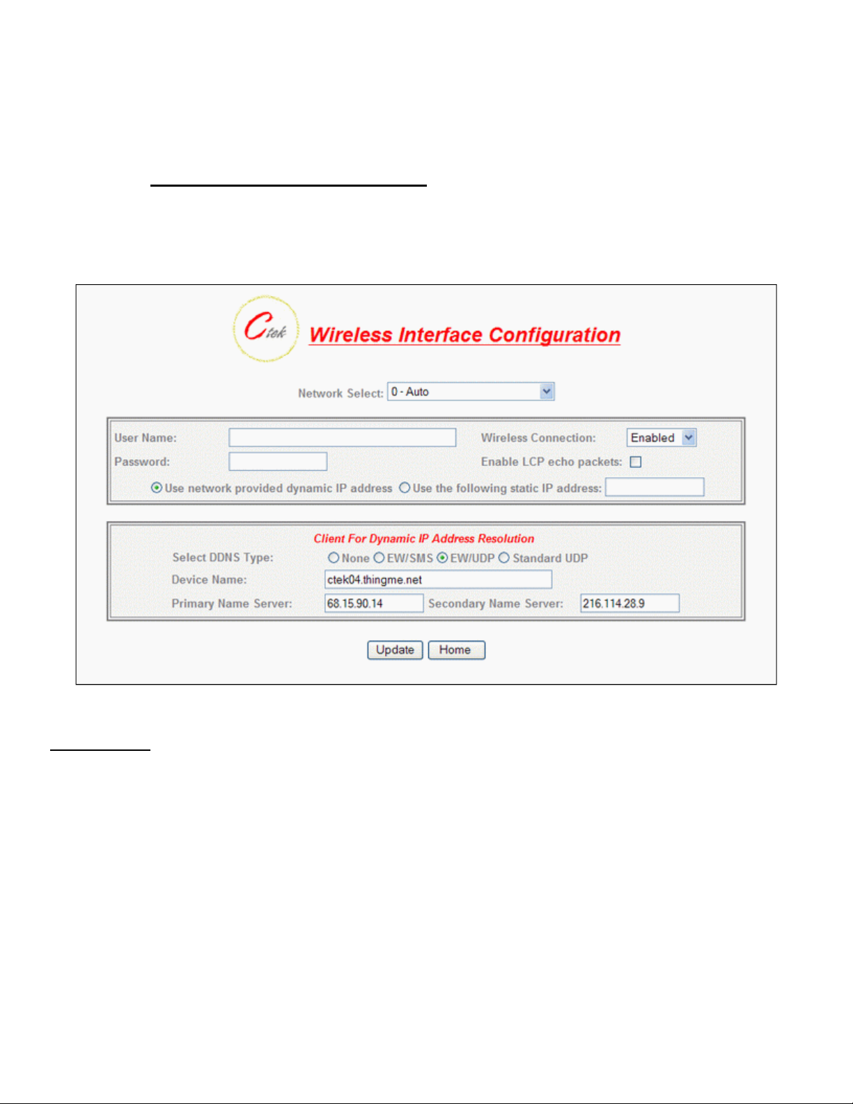
4.2.1 Configuring The Wireless Interface
The configuration screen for the Model Z4200 (EVDO and 1xRTT) wireless inte rface is shown below in Figure 8 and
described in the text following. Figure 10 and its associated text describes the wireless interface provided with the Model
Z4400 for use on HSPA, UMTS, GPRS, and EDGE networks.
Figure 9 - Z4200 (CDMA) Wireless Interface
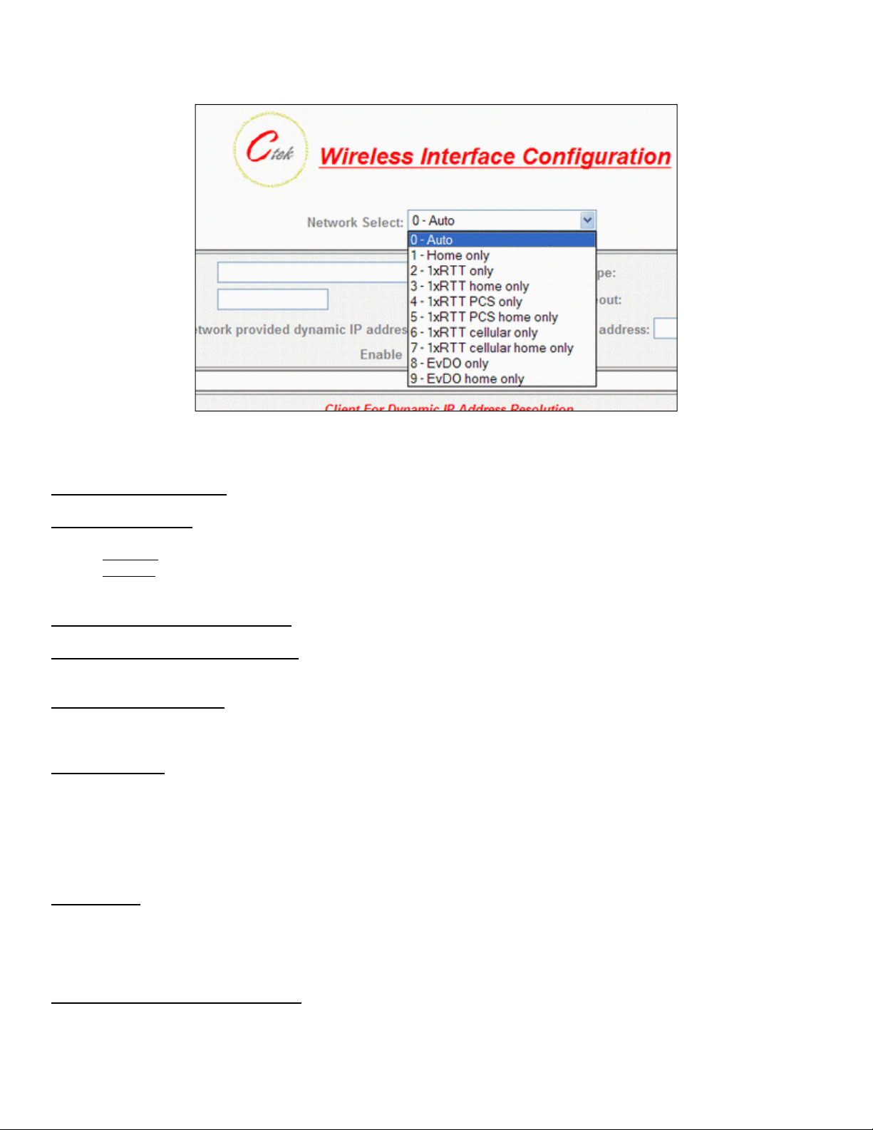
Network Select – Note: This setting should only be changed after consulting with Ctek Support. This pull down
menu allows the user to control the home network setting of the CDMA connection, effectively limiting the scope of the
Preferred Roaming List (PRL) assigned by your wireless network operator. The possible settings are shown belo w. The
EV-DO choices are only available on the Z4200.
11
26 October 2012
Figure 10 - Z4200 Network Select
User Name and Password – Required for activation on some networks. See TechNotes for specific usage.
Wireless Connection – Used to enable/disable the wireless WAN connection.
Disabled – Turn off WAN connection
Enabled – Turn off WAN connection
Use Network’s Dynamic IP Address – For most networks this will be the correct selection.
Use The Following Static IP Address – If your selected network is capable of provisioning a static IP address to your
application check this box and enter the assigned IP address. See TechNotes for network spe cific set up.
Enable LCP echo packets – Used on some International networks. For all US networks LCP echo packets should be
turned off, meaning this box should be unchecked. If you have questions check with Ctek support.
Select DNS Type – Used to select the appropriate protocol for your Dynamic DNS.
1) None – DDNS will not be used.
2) EW/SMS – Use Ctek Enhanced Wireless DDNS with SMS updates.
3) EW/UDP - Use Ctek Enhanced Wireless DDNS with UDP updates over the EV-DO/1XRTT Air Interface
4) Standard UDP – Use a standard BIND, MS2000, or MS2003 DDNS server
Device Name – Establishes the name by which this particular router will be known at the Name Server. This entry must
be a fully qualified device name and domain and is limited to 40 characters in total. It is limited to one level of name space
definition meaning that all characters to the right of the first “dot” will be assumed to be a component of the resolving
server. An example would be ctek01.thingme.net where ctek01 is the name of an individual router and thingme.net is the
name of the resolving server.
Primary and Secondary Name Server – Enter the IP address of the designated Name Server. Name resolution is not
performed on this entry meaning that a numeric IP address of the resolving server is required.
12
26 October 2012
Provide Network Name Server Facilities – Selecting Yes causes this router to provide Name Server services to client
Ctek routers configured to use it. If this option is selected additional set up in the Name Services screen will be required.
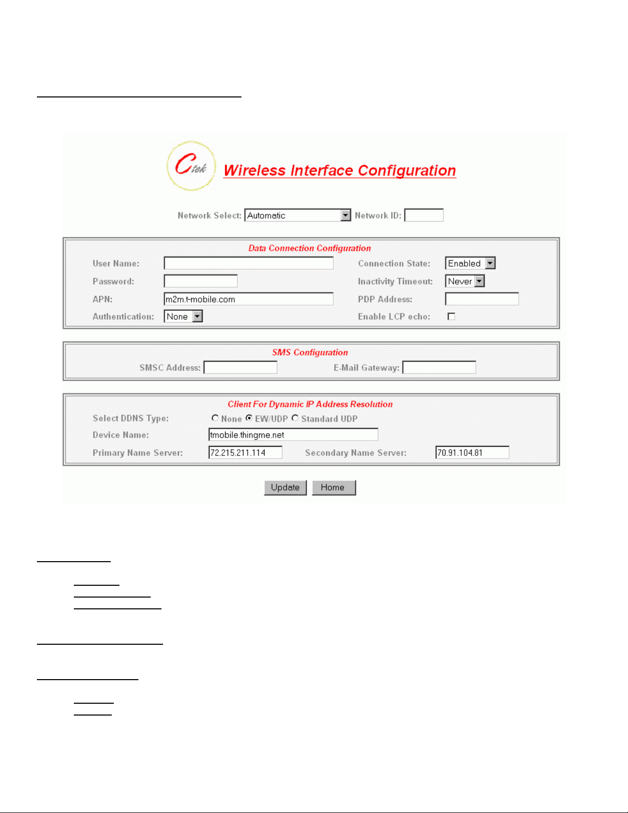
Figure 11 - Z4400 (HSPA) Wireless Interface
Network Select – Available settings are Automatic, Prefer A Network, or Demand a Network.
Automatic – Allow radio to select network based on SIM and signal quality
Prefer a Network – Similar to Automatic with a bias towards the network ID specified in the Network ID field
Demand a Network – Make every effort to use the network specified in the Network ID field
User Name and Password – Normally blank. Required for activation on some networks. See TechNotes for specific
usage.
Wireless Connection – Used to enable/disable the wireless WAN connection.
Disabled – Turn off WAN connection
Enabled – Turn off WAN connection
13
 Loading...