


TN0019 – Z1216 I/O and Z1204 Relay Module
Hardware Configuration
TN0019 - 28 March, 2011
Note: This TechNote is obsolete but continues to be available for users still
deploying the generation of I/O modules described herein. See the
TechNote Index for updates on I/O modules
Purpose:
This TechNote describes the hardware configuration of the Z1204S/U Relay module and the Z1216S/U
I/O Sensor and Control Module. These modules are components of Ctek's Automation Framework. The
Z1204S and Z1216S rely on two-wire RS485 communications and an external power source. The
Z1204U and Z1216U use USB communications for both control and power. These modules can be
managed from a Ctek SkyRouter by Ctek's Automation Control application or by a custom application.
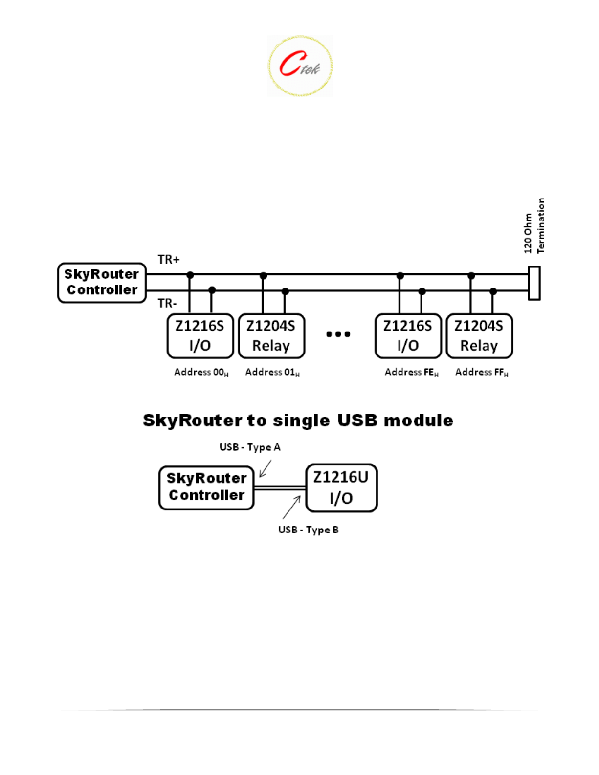
Figure 1 shows an RS485 network connected to a SkyRouter. Ctek's I/O modules can be mixed and
matched with other Ctek or non-Ctek RS485 devices on a network. Each device must have an unique
address in the range of 01 - 255 decimal or 01 - FF hexadecimal.
Note - RS485 device address 00 is reserved for Ctek's PowerMinder and should not be used for other
devices.
A single USB I/O or relay controller can be directly connected and managed by a Ctek SkyRouter. Figure
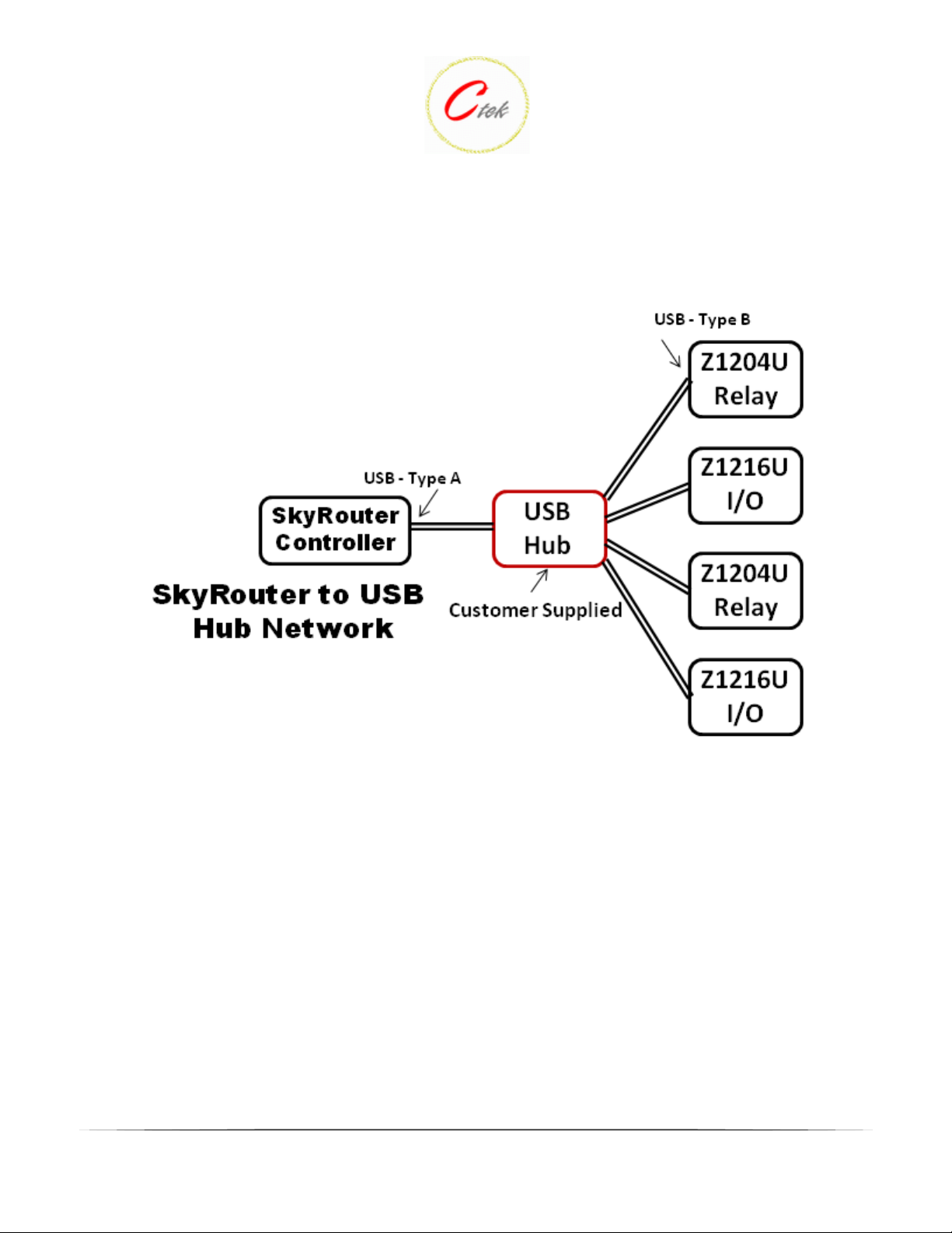
2 depicts a USB I/O connection to a single USB controller. In addition, a USB network can be
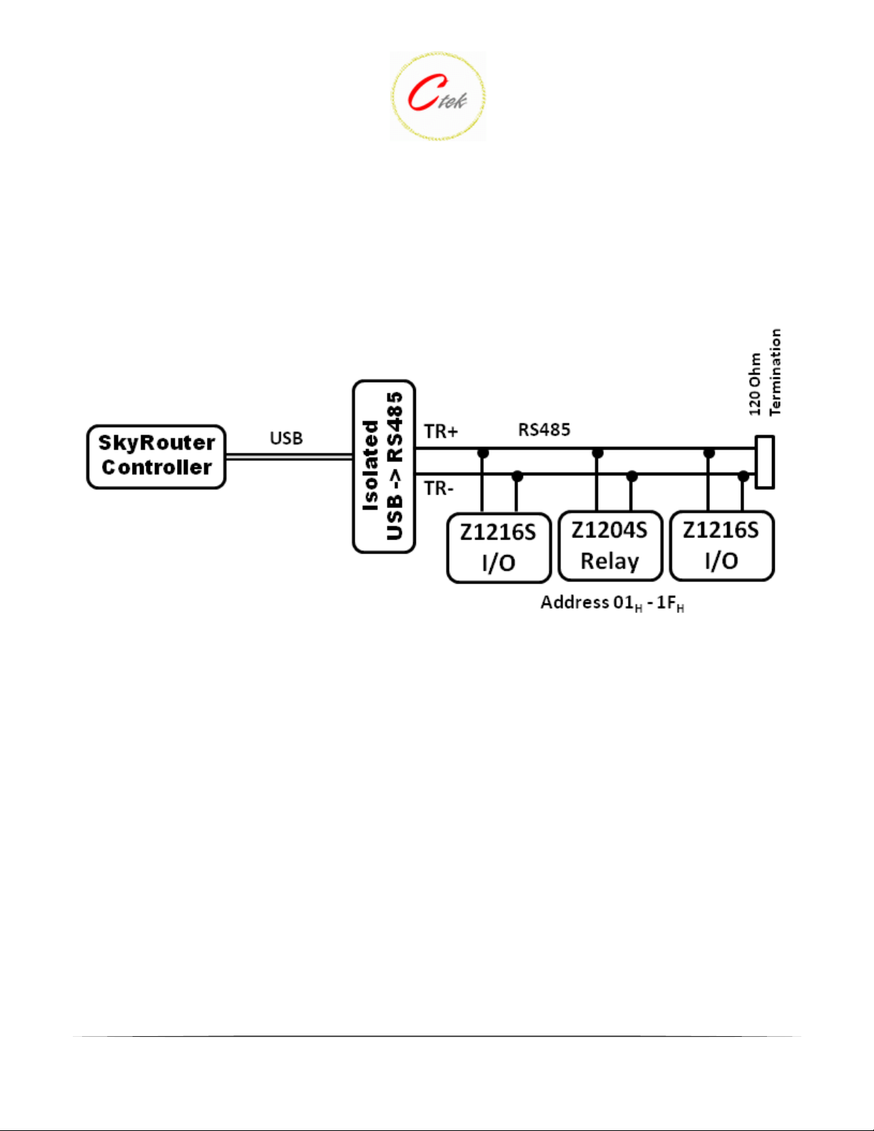
constructed with a customer supplied USB hub as shown in Figure 3. Ctek also offers an isolated USB to
RS485 converter (Figure 4) that can be used to construct a network of up to 31 I/O modules. The isolated
converter provides 2.5KV of isolation between the network and the SkyRouter. USB I/O devices are
addressed by an 8-byte address pre-programmed at the factory. USB and RS485 devices can coexist on a
single SkyRouter.
Important Note - RS485 modules are addressed with on-board jumper plugs. USB modules come pre-
addressed from the factory. RS485 modules also require an external power supply for components and
importantly for a sensor reference voltage. USB modules obtain component power and reference voltage
from the power supplied by the USB connection. Pages 2 - 7 of this document are specific to RS485
modules. The remainder of the document is applicable to bothRS485 and USB modules.
1
TN0019 – Z1216 I/O and Z1204 Relay Module
Hardware Configuration
TN0019 - 28 March, 2011
Figure 1
Figure 2 - Single USB Controller
2
TN0019 – Z1216 I/O and Z1204 Relay Module
Hardware Configuration
TN0019 - 28 March, 2011
Figure 3 - USB Hub Network
3
TN0019 – Z1216 I/O and Z1204 Relay Module
Hardware Configuration
TN0019 - 28 March, 2011
Figure 4 - Isolated USB to RS485 Converter
4

TN0019 – Z1216 I/O and Z1204 Relay Module
Hardware Configuration
TN0019 - 28 March, 2011
Addressing The Z1204S and Z1216S
Each RS485 module is addressed using jumper plugs providing an 8-bit address. The Z1204U and
Z1216U USB modules are addressed at the factory.
Figure 5 shows the Z1216S I/O module addressing jumpers set for an address of 20H. Immediately
following that 6 shows a Z1204S Relay module with an address of 01H. As noted previously all devices
connected to a single RS485 network must have a unique address.
Figure 5 - Z1216S I/O Module Addressing 20H
5

TN0019 – Z1216 I/O and Z1204 Relay Module
Hardware Configuration
TN0019 - 28 March, 2011
Figure 6 - Z1204S Relay Module Addressing 01H
6

TN0019 – Z1216 I/O and Z1204 Relay Module
Hardware Configuration
TN0019 - 28 March, 2011
Z1204/Z1216 Power and Communications
The Z1204U and Z1216U I/O modules receive power and communications over a single USB connection.
The Z1204S and Z1216S RS485 I/O modules require input power in the range of 9 - 24VDC and a twowire RS485 communications connection. If the communications cable is using a third wire (ground) to
minimize line noise it should be connected to the power supply ground connection on the module. The
physical connections for both RS485 modules are identical and are shown in Figure 7 below.
Figure 7 - Z1204S/Z1216S Power and Communications
R+ - RS485 TR+
R- - RS485 TR-
- Ground
+V - Input power Source - 9 - 24VDC
Z1204 Max Current - 160ma @12VDC
Z1216 Max Current (excluding driven outputs) - 100ma @ 5VDC
7

TN0019 – Z1216 I/O and Z1204 Relay Module
Hardware Configuration
TN0019 - 28 March, 2011
SkyRouter Connections
Figure 8 shows the connections available on a Z Series SkyRouter that can be used to interconnect with
I/O modules.
Figure 8 - Z4200U/Z4300U/Z4400U C onn ecti ons
Connector J1 (green connector) supports four separate functions, power, relay contact closure detection,
relay driver output, and the RS-485 serial port. Contact closure pins 2 and 4 are shared with the RS485
serial port. To option remove the circuit board and locate the 3-pin headers JP1 & JP2 behind the green
connector. Facing the end of the board containing the green connector JP1 and JP2 should have jumpers
center to right to use the discrete I/O (Din, Dout), and JP1 and JP2 should have jumpers center to left to
use the RS-485 serial port. Auxiliary serial port parameters (baud, parity, etc.) are set using the
RS232/485 configuration screen. From the factory the unit ships with the auxiliary RS-485 serial port
enabled and configured as a master device. The J1 pin out configuration is as follows:
Terminal Block Pin JP1 & JP2 (internal) Center to Right JP1 & JP2 (internal) Center to Left
Pin 1 Din Src – Discrete Input Source
Pin 2 Din – Discrete Input (See Appendix A) TR- of RS-485 serial port1
Pin 3 Dout Gnd – Discrete Output Ground Ground of RS-485 serial port
Pin 4 Dout - Discrete Output3 TR+ of RS-485 serial port1
Pin 5 Power supply Ground Power supply Ground
Pin 6 Power supply +12VDC Power supply +12VDC
Note 1
Note 2
Note 3
Connect a 120 ohm resistor across pins 2 --> 4 for multi-drop configurations
Available as a third wire ground for use in noisy environments
Discrete output is rated at 200ma @ 24 volts maximum sink current
2
8

TN0019 – Z1216 I/O and Z1204 Relay Module
Hardware Configuration
TN0019 - 28 March, 2011
Z1204 Relay Connections
Note - Since the I/O connections on both USB and RS485 modules are identical the remainder of this
TechNote applies to both types of modules.
The Z1204 module provides 4 relays each capable of switching a 5 amp load at either 30VDC or
240VAC. The relays are managed under software control via the RS485 interface. Each relay has a
Normally Open (NO), a Normal Closed (NC), and a common connection. Figure 9 shows the relay
connection terminal block.
Figure 9 - Relay Connections
R1 - 4 - Relay Common connection
NO - Normally Open contact
NC - Normally Closed contact
9

TN0019 – Z1216 I/O and Z1204 Relay Module
Hardware Configuration
TN0019 - 28 March, 2011
Z1216 I/O Connections
The Z1216 I/O module provides eight (8) digital outputs and eight multi-function inputs that can be
configured under software control as digital inputs, analog inputs or pulse inputs.
Digital Outputs:
Each digital output provides an open collector circuit capable of sinking 250 ma when all are active or
350 ma individually. Each output is also capable of producing a PWM (pulse width modulation) output
having 8-bit resolution at 7.8kHz.
If an external power supply is used it should be connected to the K input (Fig 11) as well as the load. The
K connection provides diode clamping to minimize spikes caused by inductive loads. The other side of
the load is connected to one of the open collector digital outputs and will be switched to ground when the
output is active. See figure 10.
Warning - The output must never exceed the maximum voltage rating of 30VDC.
Figure 10 - Digital Output Connection
Figure 11 below shows the connections for digital outputs 1 - 8. The K terminal is for the external power
source connection as described above.
10

TN0019 – Z1216 I/O and Z1204 Relay Module
Hardware Configuration
TN0019 - 28 March, 2011
Figure 11 - Digital Output Connections
Input Connections:
The Z1216 input connections support digital inputs, analog inputs, and pulse inputs. Pulse inputs are a
special class of digital inputs that invoke counting and storage. Pulse inputs have the same electrical
specifications as standard digital inputs. The mode of operation (analog, digital, or pulse) is independently
set for each input terminal under software control.
Digital Inputs: Digital inputs can be used to sense contact closure, power status or other discrete events.
Each input should be pulled high or low in its steady state by connecting the input through a current
limiting resistor to the modules reference voltage or ground. Figure 12 shows a simplified input circuit.
11

TN0019 – Z1216 I/O and Z1204 Relay Module
Hardware Configuration
TN0019 - 28 March, 2011
Figure 12 - Simple Digital Input Circuit
12

TN0019 – Z1216 I/O and Z1204 Relay Module
Hardware Configuration
TN0019 - 28 March, 2011
Analog Inputs: Inputs configured to operate in analog mode apply 12 bit analog to digital conversion
across an input voltage range of 0 - 5 volts. The reference voltage supplied on the Z1216 + connections is
nominally 5 volts. Ctek's Automation Control application provides a calibration feature to compensate for
minor variations in the reference supply. Sensors designed for other voltage ranges and current loop
sensors such those designed for 4 - 20 ma standard can be easily adapted with simple resistive networks.
Figure 13 shows the Z1216's input and reference connections.
Note - When using an external source of power for analog or digital inputs it is important to take one of
two precautions to avoid ground loops.
1 - Use a completely isolated supply
2. Connect the Z1216 ground to the external supply ground
Figure 13 - Z1216 Analog/Digital Inputs
1 - 8 - Analog/Digital Inputs
0V - Reference ground
+ - Reference supply (5 volts nominal)
13
 Loading...