

CTEK SMART PASS 120 Service Manual
MANUAL
CONGRATULATIONS
on the purchase of your new CTEK charger providing professional battery care. This charger is
included in a series of professional chargers from CTEK SWEDEN AB and represents the latest
technology in battery charging. With the CTEK D250SA and SMARTPASS 120 you can be sure of
getting maximum performance from your dual battery system.
SAFETY
CALIFORNIA PROPOSITION 65
WARNING: This product contains chemical known to the state
of California to cause cancer or reproductive toxicity.
• The D250SA and SMARTPASS 120 have been developed for 12V lead-acid batteries. Do not use
the unit for any other type of battery.
• Wear protective goggles when connecting and disconnecting batteries.
• Batter y acid is corrosive. Rinse with plenty of water immediately if you get acid on your skin or in
your eyes. Get medical assistance.
• Never use a charger with damaged electric cables. Check that the cables have not been damaged by hot surfaces, sharp edges or in any other way.
• Explosive gases are generated while lead-acid batteries are being charged. Avoid any sparking
near the battery. Use in a well-ventilated location.
• Never place the charger above the battery, and avoid covering the charger during charging.
• Disconnect the battery terminal posts before installing.
• The D250SA and SMARTPASS 120 are not spark-free.
• The installation must include a fuse in accordance with the recommendations in the table
”CABLE AND FUSE RECOMMENDATIONS”.
WARNING!
The D250SA and
SMARTPASS 120 are not
protected against reversed
polarity.
Remember that all installations in boats must comply with ISO 10133!
1. The cabling from the batteries must have fuses near the batteries.
2. The batteries must be securely fastened in a ventilated space.
3. The cabling must be run through pipe ducting, separately from 230V/110V wiring (mains power),
or secured by clips at every 30 cm/1 ft.
4. Cabling in the engine compartment must be temperature rated at 70C/ 158F.
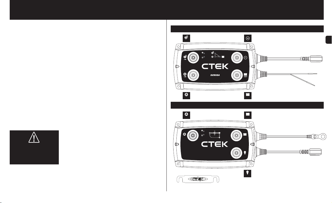
D250SA
Input Solar panel Earth Connection
+IN
Input Alternator
+IN
SMARTPASS 120
Input Alternator
+IN
+IN
SMARTPASS 120
Connector plate
Temperature sensor 2 m/6 ft.
Smart alternator cable (red) 0.2 m/0.6 ft.
Output Service battery
+OUT
Output Service battery
+OUT
+OUT
+OUT
+OUT
Negative cable connection (M8) 0.3 m/1 ft.
Temperature sensor 2 m/6 ft.
Output Consumers
EN
AGM Cable (black)
0.2 m/0.6 ft.
EN•3

D250SA
• The D250SA is a DC to DC battery charger for a dual battery system with a starter battery and a
service battery.
• The D250SA charges the service battery either from an alternator or from a solar panel, or from a
combination of both.
• The D250SA separates the batteries in a dual battery system and thereby replaces, for example, a
separation relay, VSR (Voltage Sensitive Relay), diode isolator or a mechanical battery selector.
• The D250SA can be used on its own or in combination with SMARTPASS 120. In combination,
the D250SA and SMARTPASS 120 can charge at up to 140A.
FUNCTIONS:
• Charging service battery from a conventional alternator (constant charging voltage)
The D250SA charges a service battery at up to 20A from the start battery when a conventional
alternator is running. This function is switched off when the engine is not running to prevent
discharge of the starter battery.
• Charging of a service battery from a smart alternator (with variable charging voltage)
The D250SA can charge a service battery at up to 20A from the starter battery when a smart
alternator is running. This function is switched off when the engine is not running, so as not to
discharge the starter battery. The Installation section describes how the D250SA needs to be connected in order to activate the smart alternator functions.
• Charging a service battery from a solar panel
The D250SA can charge and trickle charge a service battery from a solar panel at up to 20A.
The D250SA uses MPPT (Maximum Power Point Tracker) to maximise the power from the solar
panel.
• Separation of the starter battery and the service battery
The D250SA separates the starter battery from the service battery when the engine is not running.
• Temperature compensated charge voltage
The D250SA optimises the charge voltage by increasing the charge voltage at temperatures
below 25°C/77°F and reducing it at temperatures higher than 25°C/77°F. The functions is
always active.
• Trickle charging of the starter batter y from a solar panel
The D250SA trickle charges the starter battery from a solar panel at intervals of 3 seconds if the
service battery is fully charged.
• Optimised charging of AGM batteries
The D250SA can provide a suitable charging voltage for optimal charging of AGM (Absorbent
Glass Mat) batteries, which require a higher charge voltage than other types of lead-acid battery.
The installation section describes how the D250SA needs to be connected in order to activate the
AGM battery function.
4•EN
SMARTPASS 120
• SMARTPASS 120 is a solution for supplying current to charge and manage consumers in a dual
battery system consisting of a starter battery and a service battery.
•
SMARTPASS 120 separates the batteries in a dual battery system and thereby replaces, for example,
a separation relay, VSR (Voltage Sensitive Relay), diode isolator or a mechanical battery selector.
• SMARTPASS 120 connects the starter and service batteries together in order to charge them both
from the alternator.
• SMARTPASS 120 protects the service battery from deep discharge which would damage the
battery.
• SMARTPASS 120 supplies consumers from the alternator instead of from the service battery while
the service battery is charging, which permits faster charging.
• SMARTPASS 120 can be used on its own or in combination with D250SA. In combination, the
D250SA and SMARTPASS 120 can charge at up to 140A.
FUNCTIONS:
• Charging a service battery
SMARTPASS 120 charges the service battery from the starter battery or another current source
that is connected when the alternator is running or when the starter battery voltage is high enough.
• Battery guard
SMARTPASS 120 disconnects consumers when the service battery voltage is low in order to
avoid deep discharge, which would damage the battery. The consumers are reconnected after the
service battery voltage has increased. Connect critical consumers directly to the service battery so
they will not be disconnected if the voltage falls to lower than 11.5V.
• Start assistance
SMARTPASS 120 automatically connects the service battery to the starter battery for 10 sec to
assist, if the starter battery on its own is unable to start the engine. After the start assistance function has been activated, SMARTPASS 120 will display a fault indication until starting has been
achieved without using the start assistance function.
• Separation of the starter battery and the service battery
SMARTPASS 120 separates the starter battery from the service battery when the engine is not running.
• Assigning current source priority
SMARTPASS 120 can sense when the alternator is running and in that case supplies consumers
with current from the starter battery to work with the D250SA and maximise charging efficiency.
Otherwise the consumers are supplied with current from the service battery.
• Dynamic overcurrent protection
SMARTPASS 120 has overcurrent protection to shield the product. Overcurrent protection permits
maximum current to be sent from the alternator temporarily so that charging will be accelerated.
• Battery temperature protection
SMARTPASS 120 protects the battery by switching off charging if the service battery temperature
rises too high.
• Starter battery trickle charging
The service battery trickle charges the starter battery without assistance from the solar panel or
alternator to compensate for the self-discharge of the starter battery. The service battery charges in
3-second pulses when its voltage is higher that of the starter battery and the voltage of the starter
battery is low.
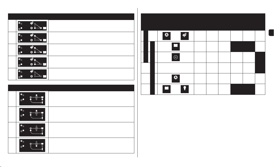
FUNCTION INDICATIONS
+OUT
+OUT
+OUT
+OUT
D250SA Explanation
1
2
3
4
5
SM AR TP AS S 12 0 Explanation
1
The service battery is being charged by the alternator.
The ser vice batter y is being charged by the solar panel.
The ser vice batter y is being charged by both the alternator and
solar panel.
The ser vice batter y is fully charged. The ser vice batter y is being
trickle charged by the solar panel.
Current saving mode, no charging in progress.
Current from alternator to service battery and consumers.
Current from service battery to consumers.
CABLE AND FUSE RECOMMENDATIONS
MIN. C ABLE SIZE
0.5 m
1 m
2 m
5 m
2 ft
3 ft.
4 mm2/
AWG12
6 mm2/
AWG10
4 mm2/
AWG12
6 mm2/
AWG10
35 mm
AWG2
35 mm
AWG2
2
2
6 ft.
4 mm2/
AWG12
10 mm2/
AWG8
4 mm2/
AWG12
10 mm2/
AWG8
35 mm
AWG2
35 mm
AWG2
2
2
UNIT CABLE
+OUT
4 mm2/
AWG12
+IN
4 mm2/
AWG12
4 mm2/
AWG12
4 mm2/
AWG12
2
35 mm
AWG2
2
35 mm
AWG2
+IN
+OUT
D250SA
Connector plate*
+IN
SMARTPASS 120
+OUT
*If the D250SA and SMARTPASS 120 are installed in different locations and the accompanying connector plate is
not used, please follow the recommendations in the table.
15 f t.
6 mm2/
AWG10
4 mm2/
AWG12
10 mm2/
AWG8
50 mm
AWG1
2
10 m
30 ft.
10 mm2/
AWG8
4 mm2/
AWG12
10 mm2/
AWG8
50 mm
AWG1
30A
30A
2
300A
300A
FUSE
EN
2
3
4
Current from alternator to service battery and consumers.
Current from alternator to consumers. The ser vice batter y is
charged by the D250SA .
Trickle charging of the starter battery from the service battery.
EN•5
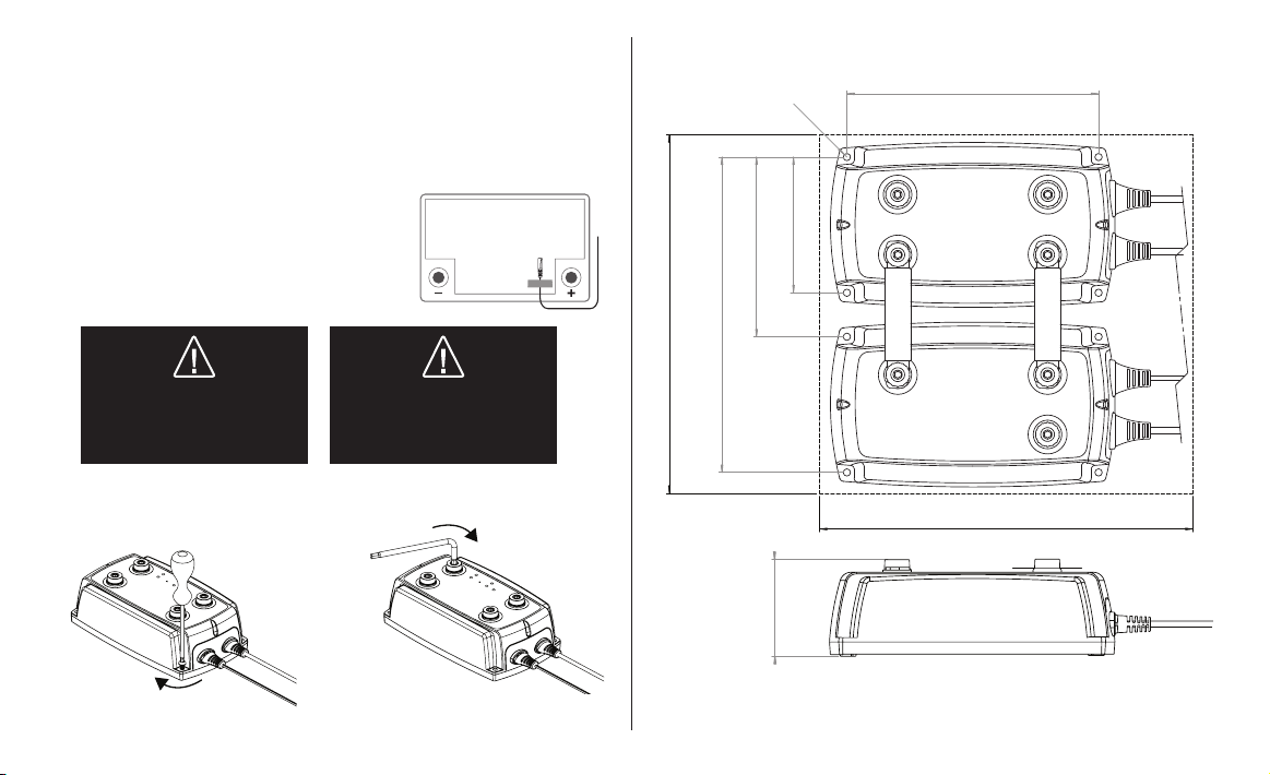
65mm / 2,53 inches
INSTALLATION
1. Install the apparatus on a smooth surface where it can be fi rmly secured and where it is not
exposed to fuel, oil or dirt. To obtain the correct distance, start by fi tting the two units together with
the accompanying connector plate (see Figure 3) before they are fi nally fastened to the smooth
surface.
2. Secure the apparatus with, for example, M4 or ST4.2 screws at each corner (see Figure 1).
3. Before connecting the cables, ensure that the negative terminal post on the battery is not connected.
4. Connect the cables to the apparatus connections by securing screws (M8) (see Figure 2).
Use an Allen key - tightening by hand without a tool is not enough.
5. Use tape (see Figure 4) to secure the temperature sensor
to a clean fl at surface above the service battery. Position the
sensor as close to the positive terminal post as possible.
6. Connect the battery negative terminal post.
Figure 4
WARNING!
The D250SA and SMARTPASS 120
are not protected against reversed
polarity. Disconnect the battery
terminal posts before installation.
WARNING!
The D250SA and SMARTPASS 120
are not spark-free.
Ensure good ventilation.
RECOMMENDED TIGHTENING TORQUES
Figure 1
Figure 2
8 Nm/71 lb-in
Allen key
DIMENSIONS
Figure 3
120mm/4,72 inches
240mm / 9,44inches
210mm/8,29 inches
Ø4,9 mm
0,19 inches
90mm/3,57 inches
168mm/6⅝ inches
250mm / 9,84inches
6•EN
2 Nm/18 lb-in
 Loading...