


Application Note
Ctek Automation Control Application
APN007
Release 4.02.02
Ctek – Things That Move Data
.

25 July 2014
i
Contents
TABLE OF FIGURES.........................................................................................................................................................IV
INTRODUCTION: .............................................................................................................................................................. 1
THEORY OF OPERATION ............................................................................................................................................... 1
NAVIGATION AND TOP LEVEL FUNCTIONS: ........................................................................................................... 2
Automation Control Panel.................................................................................................................................................................2
Automation Control Configuration ....................................................................................................................................................2
USER INTERFACE AND CONFIGURATION SPECIFICS ........................................................................................... 4
Execute New Configuration ...............................................................................................................................................................4
Unit Configuration .............................................................................................................................................................................4
Location Name: ...................................................................................................................................................................................... 5
SMS Remote Control: ............................................................................................................................................................................. 6
Logging On/Off:...................................................................................................................................................................................... 6
Log Rate: ................................................................................................................................................. Error! Bookmark not defined.
Alarms On/Off: ....................................................................................................................................................................................... 6
Alarm Delivery Method: ......................................................................................................................................................................... 6
Destination Phone Number for Alarms:................................................................................................................................................. 6
Destination email address for Alarms: ................................................................................................................................................... 6
Log Delivery Parameters: ...................................................................................................................................................................... 6
Email address for this device: ................................................................................................................................................................ 6
Email User Name and Password ............................................................................................................................................................ 6
SMTP Server Address and Port: ............................................................................................................................................................. 6
Authentication and SSL Encryption:....................................................................................................................................................... 7
Display Group Names:............................................................................................................................................................................7
I/O Modules ......................................................................................................................................................................................7
Add:........................................................................................................................................................................................................ 8
Delete:.................................................................................................................................................................................................... 8
Replace:.................................................................................................................................................................................................. 9
Disable.................................................................................................................................................................................................. 10
Enable .................................................................................................................................................................................................. 10
Configure Outputs ...........................................................................................................................................................................11
Output Configuration Screens ............................................................................................................................................................. 12
Configure Inputs ..............................................................................................................................................................................15
Input Configuration Screens ................................................................................................................................................................ 15

25 July 2014
ii
More About Digital Inputs and Outputs ..........................................................................................................................................24
Understanding The Input and Output Polarity Setting ........................................................................................................................ 24
Min/Max Range and Sensor Calibration: ............................................................................................................................................ 25
Analog Input Processing....................................................................................................................................................................... 26
Thresholds............................................................................................................................................................................................ 26
Thresholds – An Example .....................................................................................................................................................................27
Pulse Input - Latching ........................................................................................................................................................................... 28
Configure Formulas .........................................................................................................................................................................29
Current Input Pin: ................................................................................................................................................................................ 30
Other Input Pin: ................................................................................................................................................................................... 30
Output Pin = ......................................................................................................................................................................................... 30
Constant Value = .................................................................................................................................................................................. 30
Correction: ........................................................................................................................................................................................... 30
Min Range: ........................................................................................................................................................................................... 30
Max Range: .......................................................................................................................................................................................... 30
Max – Min Range ................................................................................................................................................................................. 30
Min Units:............................................................................................................................................................................................. 30
Max Units: ............................................................................................................................................................................................ 30
Max – Min Units: .................................................................................................................................................................................. 31
Ent ........................................................................................................................................................................................................ 31
Sub ....................................................................................................................................................................................................... 31
Add.......................................................................................................................................................................................................31
Mul....................................................................................................................................................................................................... 31
Div ........................................................................................................................................................................................................ 31
Xch .......................................................................................................................................................................................................31
An explanation of the standard conversion formula ........................................................................................................................... 31
Programs .........................................................................................................................................................................................33
Program Edit Fields .............................................................................................................................................................................. 34
Function Library ................................................................................................................................................................................... 34
LOG AND LOGGING ........................................................................................................................................................ 35
Set Up and Management .................................................................................................................................................................35
Logging Rules...................................................................................................................................................................................35
Digital Inputs ........................................................................................................................................................................................ 35
Analog, Pulse, and Numeric In puts ...................................................................................................................................................... 35
Digital Outputs ..................................................................................................................................................................................... 35
Numeric Outputs.................................................................................................................................................................................. 35
THE CONTROL PANEL ..................................................................................................................................................36
Provisioning the Control Panel ........................................................................................................................................................36
APPENDIX A – FUNCTION LIBRARY .........................................................................................................................38
Function List ....................................................................................................................................................................................38
Function Descriptions ......................................................................................................................................................................38

25 July 2014
iii
Digital I/O – Set .................................................................................................................................................................................... 38
Numeric I/O – Set................................................................................................................................................................................. 39
Math functions..................................................................................................................................................................................... 39
Note on Remote Commands ................................................................................................................................................................ 40
Remote I/O - Set................................................................................................................................................................................. 40
Note On Timer/Counter ....................................................................................................................................................................... 40
Timer/Counter/Ext/Clk – Start [Note – Changed In Release 4.02.02]................................................................................................. 42
Timer/Any – Stop ................................................................................................................................................................................. 43
Important Notes on Motor Group Control .......................................................................................................................................... 43
Motor Group Control ........................................................................................................................................................................... 44
Application Status - Set ........................................................................................................................................................................ 45

25 July 2014
iv
Table of Figures
FIGURE 1 – THEORY OF OPERATION ................................................................................................................................................1
FIGURE 2 - TOP LEVEL NAVIGATION ...............................................................................................................................................2
FIGURE 3 - AUTOMATION CONTROL CONFIGURATION MENU..................................................................................................4
FIGURE 4 - UNIT CONFIGURATION....................................................................................................................................................5
FIGURE 5 - MANAGE I/O MODULES...................................................................................................................................................7
FIGURE 6 - MODULE ADD SCREEN....................................................................................................................................................8
FIGURE 7 - MODULE DELETE SCREEN .............................................................................................................................................9
FIGURE 8 – I/O MODULE REPLACEMENT.........................................................................................................................................9
FIGURE 9 - DISABLE I/O MODULE....................................................................................................................................................10
FIGURE 10 - ENABLE MODULE.........................................................................................................................................................10
FIGURE 11 - OUTPUT CONFIGURATION SCREEN .........................................................................................................................11
FIGURE 12 OUTPUT - PHYSICAL/DIGITAL .....................................................................................................................................12
FIGURE 13 - OUTPUT VIRTUAL/DIGITAL .......................................................................................................................................12
FIGURE 14 - OUTPUT VIRTUAL/NUMERIC .....................................................................................................................................13
FIGURE 15 - OUTPUT PIN DEFINITIONS..........................................................................................................................................14
FIGURE 16 - INPUT CONFIGURATION SCREEN .............................................................................................................................15
FIGURE 17- INPUT PHYSICAL/DIGITAL ..........................................................................................................................................16
FIGURE 18 - INPUT PHYSICAL/ANALOG.........................................................................................................................................16
FIGURE 19 - INPUT PHYSICAL/PULSE .............................................................................................................................................17
FIGURE 20 - INPUT VIRTUAL/DIGITAL ...........................................................................................................................................17
FIGURE 21 - INPUT VIRTUAL/NUMERIC.........................................................................................................................................18
FIGURE 22 - INPUT PIN DEFINITIONS..............................................................................................................................................21
FIGURE 23 - INPUT SOURCES (DIGITAL) ........................................................................................................................................22
FIGURE 24 - INPUT SOURCES (DIGITAL VIRTUAL)......................................................................................................................22
FIGURE 25 - INPUT SOURCES NUMERIC.........................................................................................................................................23
FIGURE 26 - INPUT DEFINITIONS (NUMERIC) ............................................................................................................................... 24
FIGURE 27 - ANALOG INPUT PROCESSING....................................................................................................................................26
FIGURE 28 - THRESHOLD AND DIRECTION...................................................................................................................................27
FIGURE 29 - INPUT FORMULA SELECTION SCREEN....................................................................................................................29
FIGURE 30 - EDIT INPUT FORMULA.................................................................................................................................................30
FIGURE 31 - STANDARD CONVERSION FORMULA ...................................................................................................................... 32
FIGURE 32 – PROGRAM SELECT.......................................................................................................................................................33
FIGURE 33 – PROGRAM EDIT SCREEN ............................................................................................................................................34
FIGURE 34 - CONTROL PANEL SELECTION AT LOGIN................................................................................................................ 36
FIGURE 35 - SAMPLE CONTROL PANEL DISPLAY........................................................................................................................37
Application Note – Automation Control Application
APN007 25 July, 2014
1
Introduction:
Ctek's Automation Manager is an optional firmware application available for the Ctek
Z4200/Z4400 series SkyRouter. It provides the logic and control necessary to create
sophisticated automation applications that evaluate analog, digital, and pulse sensor inputs, and,
based on sensor inputs, and programming logic, control output devices.
The Automation Manager also provides a simple, GUI based rapid development environment
used to create and deploy applications using the Automation Manager
Theory of Operation
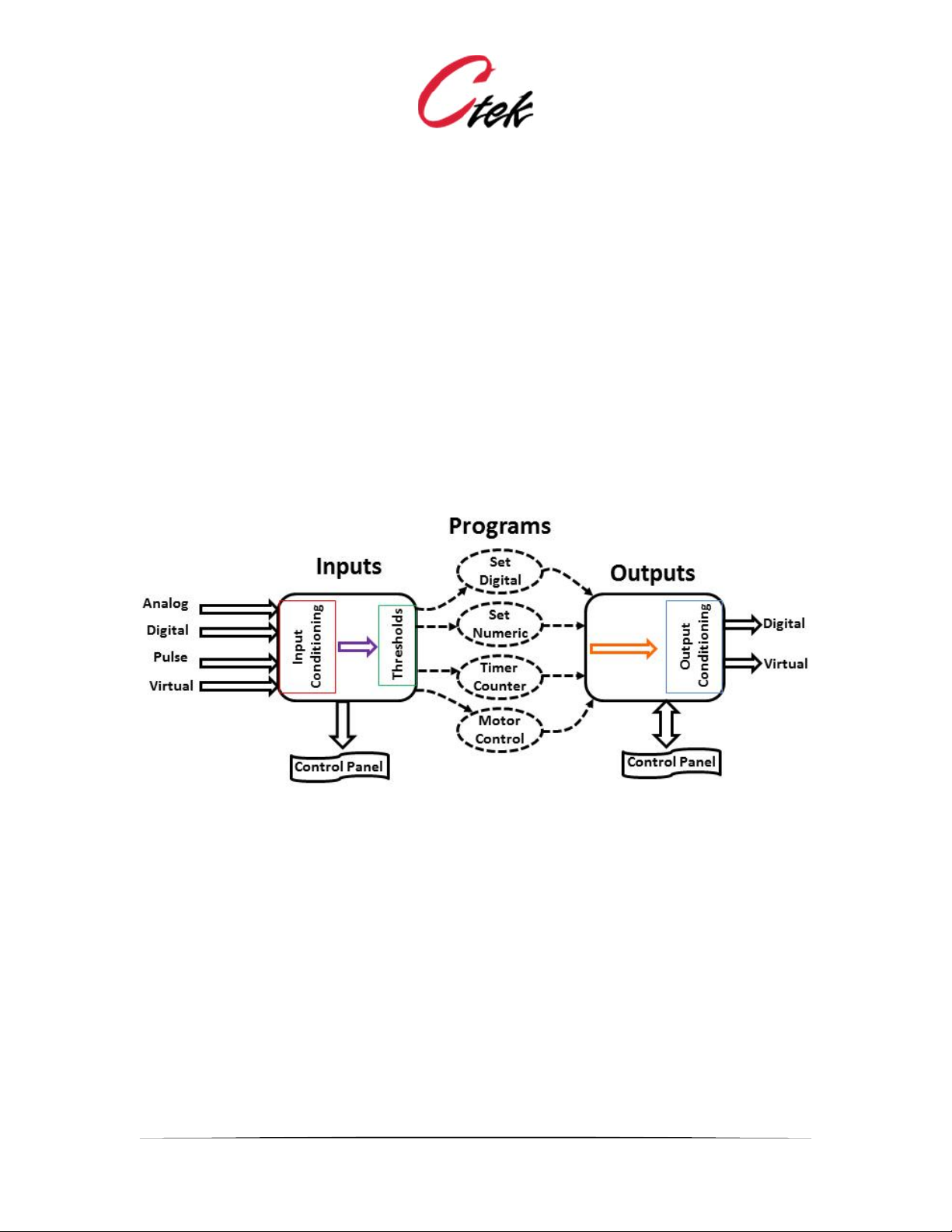
Figure 1 depicts the high-level operation of Ctek’s Automation manager. The text below figure 1
explains the flow of information through the Automation Manager.
Figure 1 – Theory of Operation
The Automation Manager is an intelligent controller, implemented in software that reacts to inputs
by controlling outputs. In their simplest form inputs are a sensors representation of a real world
value e.g. temperature, pressure, open, closed, etc. And, in their simplest form outputs are
control signals directed back into the real world to start motors, light lights or turn on heaters. The
class of inputs and outputs coming from the real world and directed back into the real world are
called physical inputs and outputs.
Inputs are connected to outputs by programs. A program can only be initiated by an input. On an
input the initiation of a program occurs as a result of the input reaching a defined state or
threshold. For digital inputs the thresholds are true and false while for analog, pulse, and numeric
inputs there can be many threshold values assigned to a single input, each capable of initiating its
own program. In summary physical inputs receive information from sensors and, at predefined
thresholds react to that information by initiating programs that control outputs.
There is another class of inputs and outputs that are known as virtual inputs and outputs or virtual
pins. Virtual pins exist only within the scope of the Automation Control software, they have no
physical connection. Virtual pins can be read and written to, modified by Boolean calculations
Application Note – Automation Control Application
APN007 25 July, 2014
2
(digital), basic math functions (numeric), and can be assigned event thresholds. Virtual pins are
useful to modify processing logic, store intermediate results, and to display values derive from
programs. Just like physical pins virtual inputs are temporary while virtual outputs are persistent.
Note – This document often refers to inputs and outputs as pins or input pins or output pins or
virtual pins depending on their origin.
Navigation and Top Level Functions:
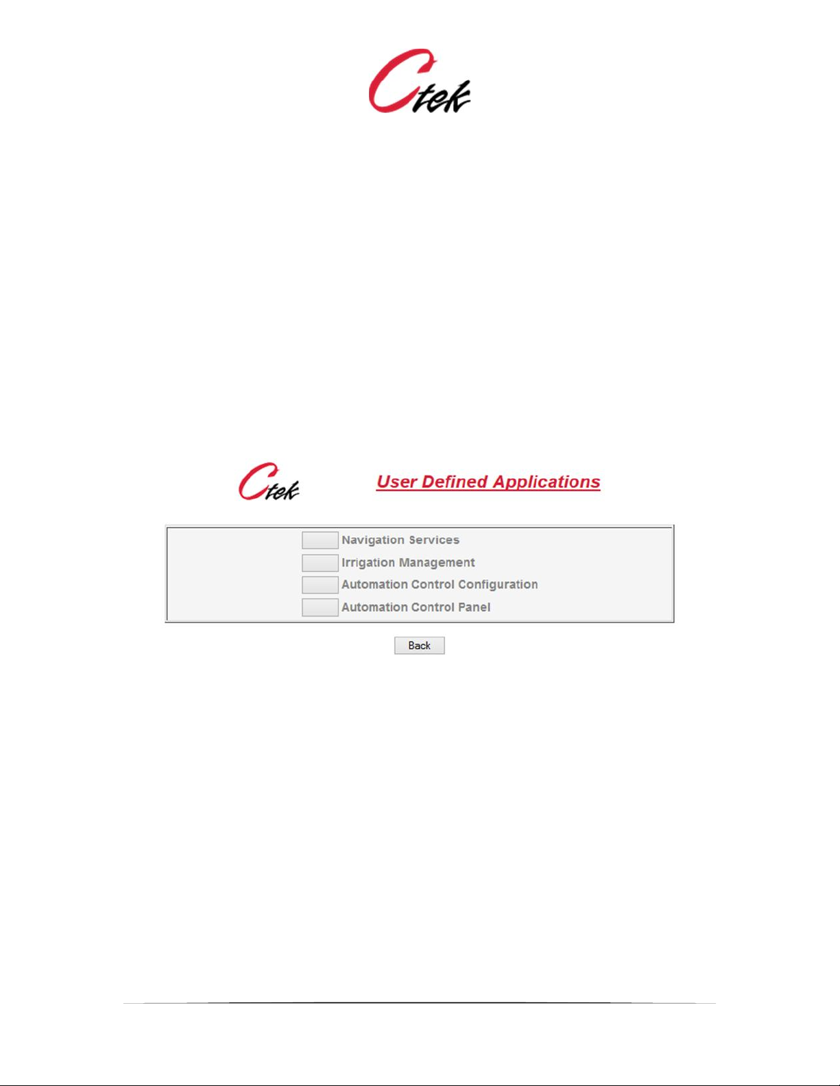
When installed the Automation Control application is found under the applications selection on
the top level SkyRouter administration screen. When selected, the application button presents the
following navigation menu. The last two menu items shown below are related to the Automation
Control option. Other menu choices may also appear depending on the set of features enabled
on the SkyRouter.
Figure 2 - Top Level Navigation
Automation Control Panel
The Automation Control Panel selection provides user access to a dashboard style control and
display of inputs and outputs that have been previously selected. Portions of this functionality are
covered in Unit Configuration, Inputs, and Outputs discussion. A complete description of the
Control Panel is found after the configuration section.
Automation Control Configuration
The Automation Control Configuration selection provides access to the screens used to configure
the application characteristics of the overall application environment, the number and type of I/O
modules installed, specific characteristics for each input and output on each I/O module, and the
formulas and functions that are applied to specific sensors and outputs.
For new installations the recommended sequence is:
1. Configure the unit
2. Configure the modules installed with this unit
3. Configure inputs on each installed module

Application Note – Automation Control Application
APN007 25 July, 2014
3
4. Configure outputs on each installed module
5. Create and assign formulas as required
6. Create and assign programs as required
Once configuration has been completed the selections are deployed using the Execute New
Configuration button. If logging is used the Logs selection can provide useful information about
system operation and can also be used to debug sensor and output installations.
Application Note – Automation Control Application
APN007 25 July, 2014
4
User Interface and Configuration Specifics
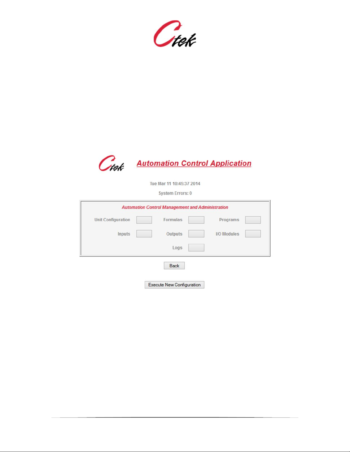
Selecting the Automation Control Configuration item presents the following menu from which the
user can install, configure, and adjust settings on I/O modules and sensors.
Note: System Errors indicates entries made as a result of this application since the last time the
box was restarted. System errors can be caused by a number of events but one common source
is communications problems with I/O modules. Contact Ctek or see TechNotes to recover the
system log contents.
Figure 3 - Automation Control Configuration Menu
Execute New Configuration
The Execute New Configuration button must be pressed before any changes made on any edit
screens will be deployed. The only exception to this rule is that outputs that are changed from
their Output edit screen will take effect immediately and do not require a New Configuration.
A new control panel view is also generated during a new configuration.
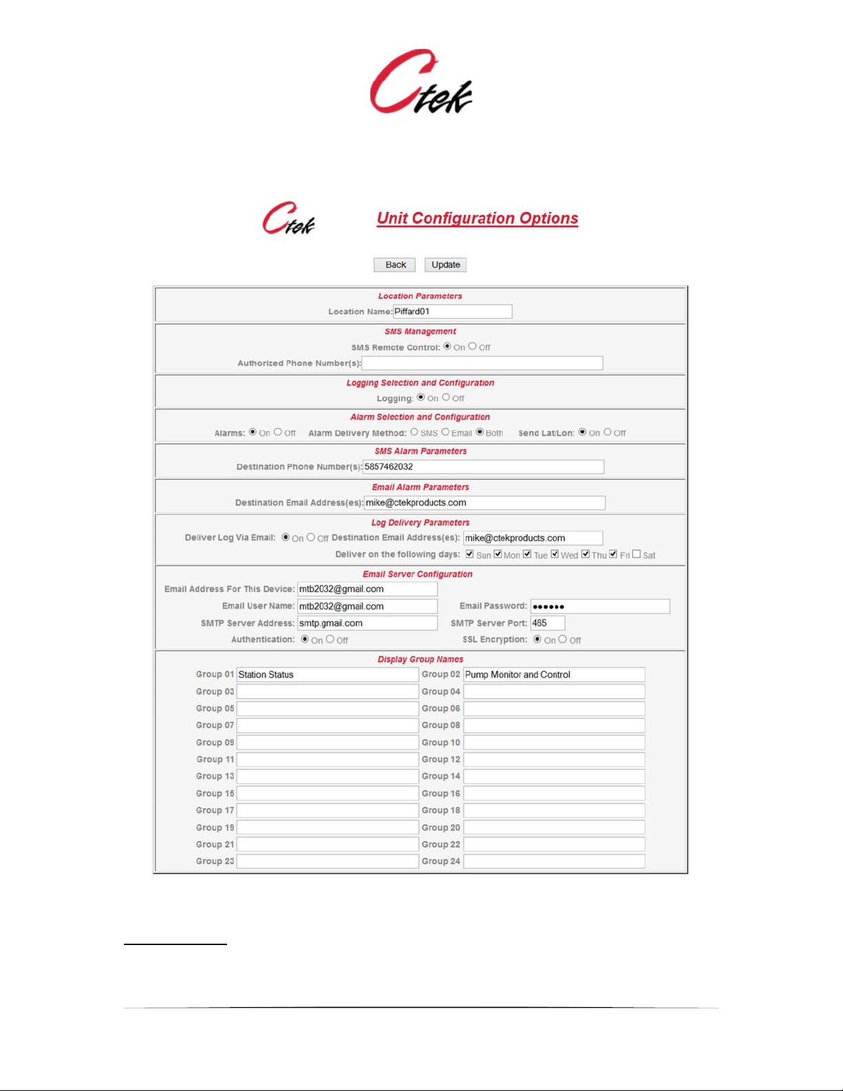
Unit Configuration
Selecting the Unit Configuration menu item causes the screen shown in Figure 4 to be displayed.
A description of each field follows the screen image.
Application Note – Automation Control Application
APN007 25 July, 2014
5
Figure 4 - Unit Configuration
Location Name:
A descriptive name assigned to this controller and its associated I/O modules

Application Note – Automation Control Application
APN007 25 July, 2014
6
SMS Remote Control:
Enable or disable SMS read/write control/monitoring of automation control I/O pins. (Introduced in
release 4.2 – see TechNote TN009 for details)
Authorized Phone Numbers:
A list of between 0 and 5, 10-digit, space separated phone numbers that are permitted to use the
SMS Remote Control feature. A blank field blocks all phone numbers. The * (star) character
allows any number. Although its use is not recommended the * character will also permit SMS
control via the carrier’s email to SMS gateway.
Logging On/Off:
Enable or disable logging. Log files are formatted in the comma separated value (CSV) format
and can be read and manipulated with a spread sheet program such as Excel. Inputs are logged
at a rate defined on each input pin. Output logging is set to either on or off on each individual
output pin. See Logging rules section.
Alarms On/Off:
Enable or disable alarms for the entire controller. Alarms can also be enabled or disabled for
each individual input.
Alarm Delivery Method:
Select whether alarms will be delivered by SMS (text messaging), email, or both.
Send Lat/Lon:
Send the current position (latitude and longitude) of the unit with all alarm entries, both SMS and
email.
Destination Phone Number for Alarms:
The phone number of the handset or device that will receive SMS alarms.
Destination email address for Alarms:
The email address that will receive alarms
Log Delivery Parameters:
Logs are files containing comma separated values that can be directly read into a spread sheet or
database application. Logging options are available for each input and output. Logs can be
delivered by email on a schedule established in this panel.
Email address for this device:
If the controller is going to send email alarms and logs it will require an email address to use as
the sender. This is typically an email address from the customers email domain. All boxes in a
network can use the same email address.
Email User Name and Password
Login information for the SkyRouter email client to use when connecting to the customer's email
server to send alarms and reports.
SMTP Server Address and Port:
Information required about the customer's email server so the SkyRouter can connect to it to
send reports and alarms.
Application Note – Automation Control Application
APN007 25 July, 2014
7
Authentication and SSL Encryption:
Settings specific to each email SMTP server.
Display Group Names:
User assigned names of logical groupings of inputs and outputs that will be used to organize the
display of the Control Panel. Both inputs and outputs can be organized under a single group
name. For example a Power Control group could have a button to turn on/off power and a current
measurement to display the amount of current being drawn.
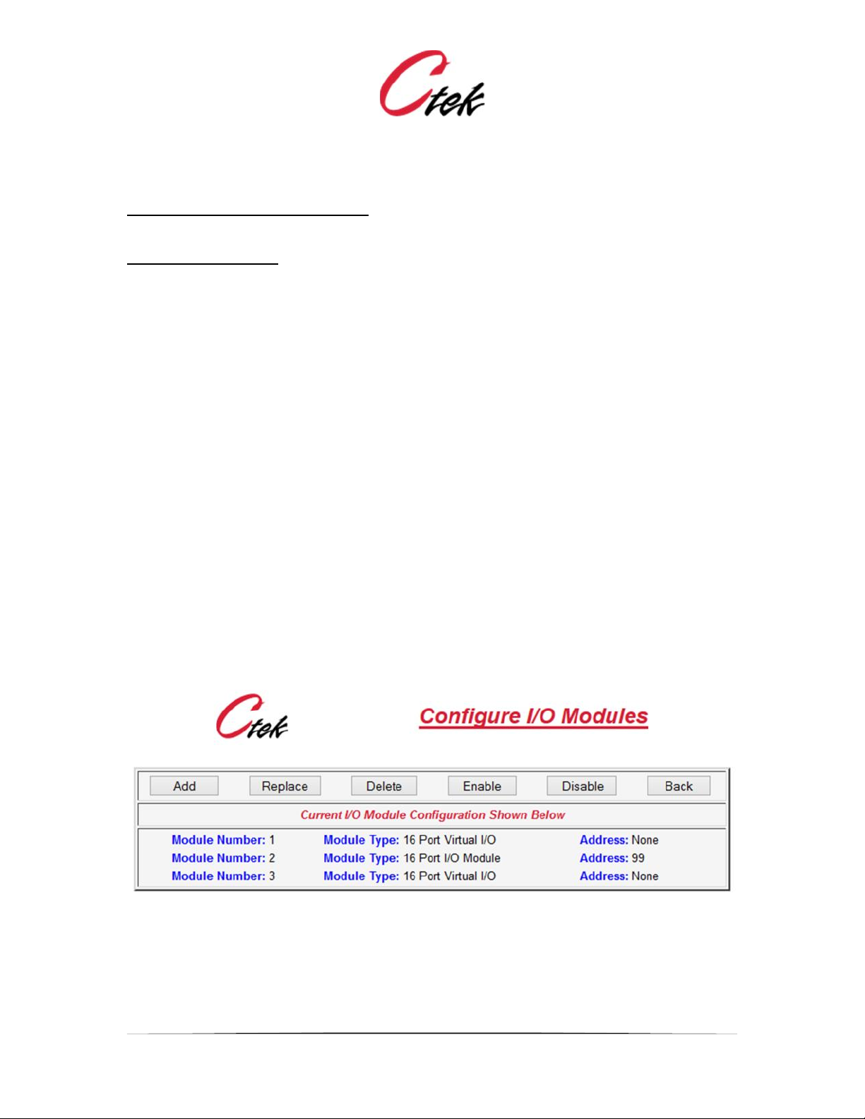
I/O Modules
The I/O modules screens allow the user to Add, Delete, Replace, Enable, or Disable an I/O
module. When an I/O module is added its inputs and/or outputs are automatically assigned. For
relay modules four outputs are automatically assigned. When adding a 16-port I/O module eight
unassigned (not initialized) inputs and eight digital outputs are automatically created. Inputs and
outputs are assigned sequential numbers as modules are installed. To convert an unassigned
input or output to a specific type (analog, digital, pulse, or numeric) the Configure Inputs and
Configure Outputs screens are used to select a specific edit function for the selected pin type.
Replace is a special case designed for maintenance. When using the replace function only the
boards address may be changed and the pre-existing configuration will be assigned to the new
address. The Replace function is useful for both replacing a defective module and to re-address
an existing working module. The Enable and Disable functions apply only to physical modules.
When a physical module is disabled it is taken out of the communications processing meaning
that it is not polled. All settings remain intact and when the module is re-enabled communications
will resume. This feature can be useful in troubleshooting communications problems when
multiple modules are on one string.
Figure 5 - Manage I/O Modules
Application Note – Automation Control Application
APN007 25 July, 2014
8
ABOUT I/O MODULE ADDRESSING
I/O module part numbers B1204S (4-port relay), B1216S (16-port) and Z1216S use RS485
communications. A default address of 99 is assigned to these modules when they leave the
factory. Their addresses may be reassigned under program control from the replace function
under the Configure I/O Modules screen. To readdress these modules first add them (Add
function) as module address 99. Once added the module may be selected by its module number
(not address) and readdressed by doing a replace on that module number with a similar type
module assigned a different address.
NOTE – If a module assigned address 99 is already installed it will either have to be temporarily
disconnected from the RS485 string (use Disable) or readdressed using the process below before
an additional module can be installed using this process. When a module is readdressed all of its
input and output settings are retained so there is no penalty for readdressing a module currently
addressed at 99.
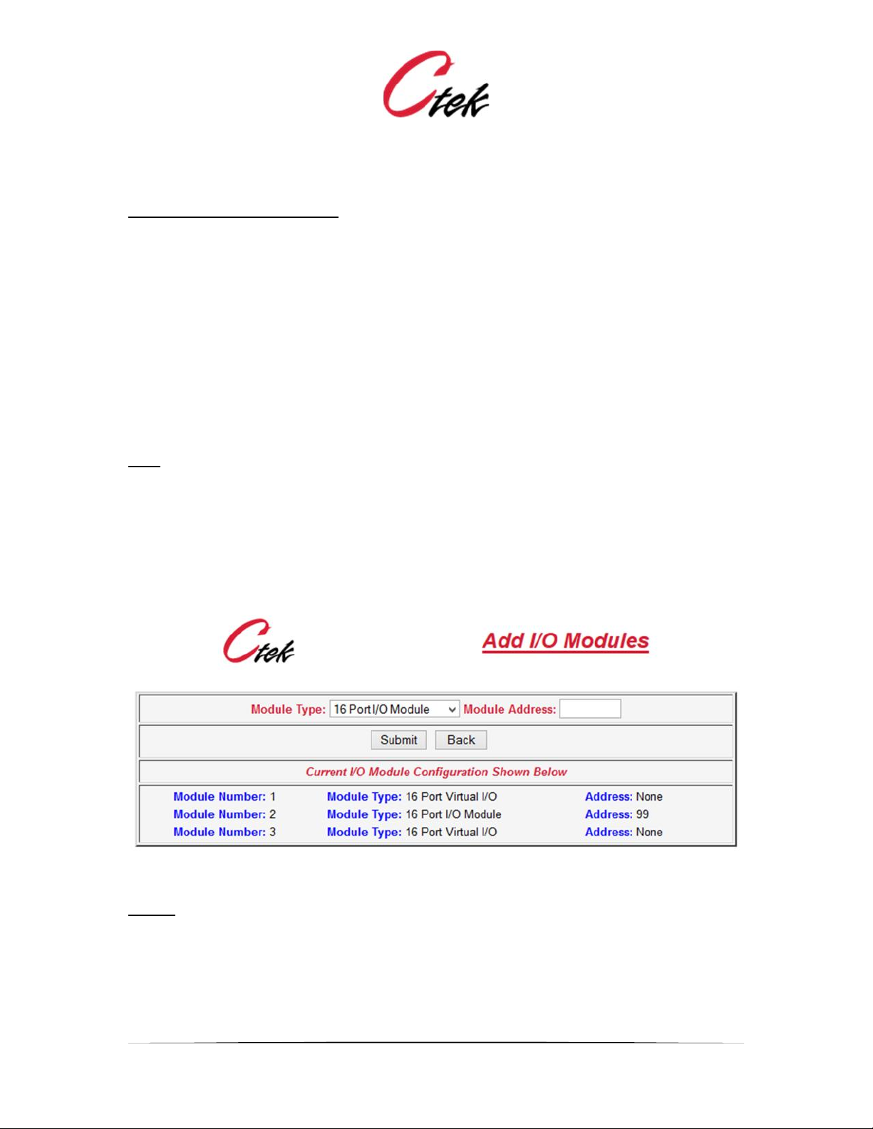
Add:
Add is used to create a new module. When Add is selected the screen shown in Figure 6 will be
displayed. A module type and module address are assigned by the user and submit is pressed.
The newly created module will then be displayed in the module inventory and its associated
inputs and/or outputs will be displayed on those screens. As previously discussed all newly
created modules having inputs will be created with all inputs defined as unassigned. An RS485
module should be assigned a two character hexadecimal address between 01 and FF. RS485
address 00 is reserved for Ctek's PowerMinder module. USB modules are assigned an eight
character address which is supplied with the module.
Figure 6 - Module Add Screen
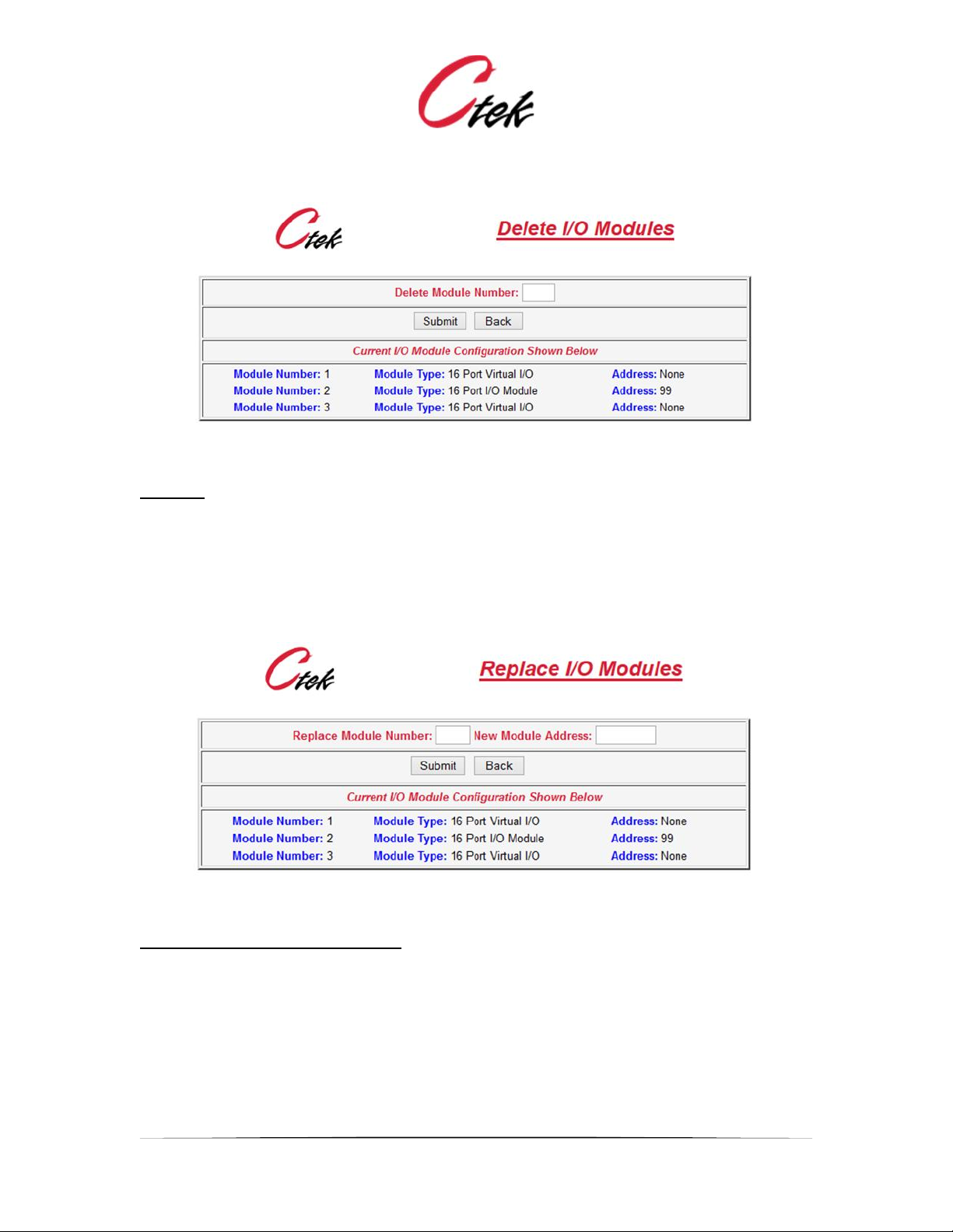
Delete:
Delete is used to remove a module from the overall configuration. When selected the Delete
screen will be displayed as shown in Figure 7. To delete a module enter the modules number and
press submit. When a module is deleted all of its input and output settings are permanently
erased.
Application Note – Automation Control Application
APN007 25 July, 2014
9
Figure 7 - Module Delete Screen
Replace:
The replace function has three purposes. First it is used to replace an existing module with a
spare. Secondly it can be used to readdress an existing module. In either case all settings
associated with that module will be preserved.
When selected the Replace Module screen will be displayed as shown in Figure 8. To replace a
module in the inventory enter the module number and the address to be assigned to the new
module, and press submit. The input/output configuration of the old module is assigned to the
new address.
Figure 8 – I/O Module Replacement
Restore a Modules Default Address
The replace function can also be used to restore the default (address 99) setting of a module. To
accomplish this connect the module with the unknown address to an SkyRouter Automation
controller. Using the Add function add the module with any address. At this point the module will
not function properly but will appear in the module line up with the address assigned. Next, using
the replace function replace the module having the made up address with the text default in the
address field. The module will be assigned an address of 99 and after a program reload will begin
functioning at that address. Once this is accomplished the module can then be readdressed
(again using the replace function) to any address desired.
Application Note – Automation Control Application
APN007 25 July, 2014
10
Note:
The default commend described above uses a broadcast that will set the address of all physical
modules to 99. You may want to disconnect modules from the line up that do not require their
address to be resored to default.
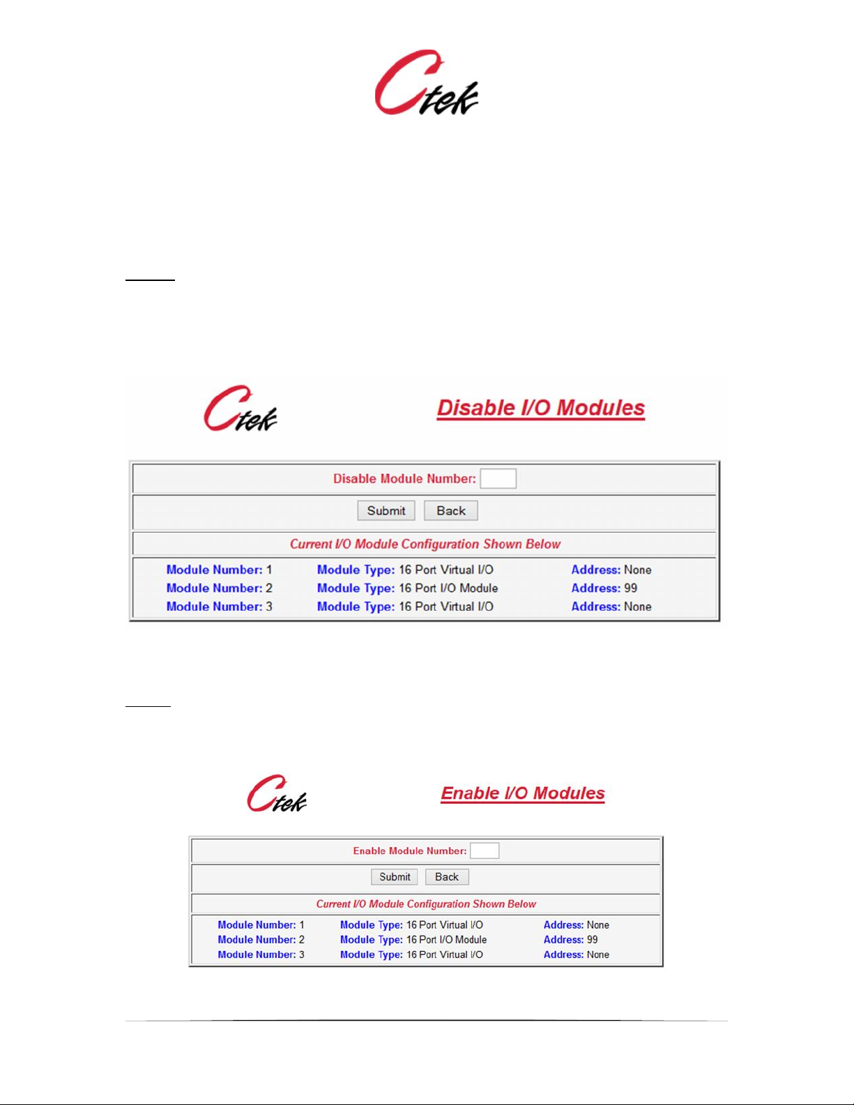
Disable
Disabling a module removes it from the communications routine. All set up information for the
disabled module remains intact. Disable can be a useful troubleshooting tool when diagnosing
communications problems or configuration issues.To disable a module enter its module number
and press submit.
Figure 9 - Disable I/O Module
Enable
Enabling a module returns a disabled module to service. Setting previously stored on the module
will be used. To enable a module enter its module number and press submit.
Figure 10 - Enable Module
Application Note – Automation Control Application
APN007 25 July, 2014
11
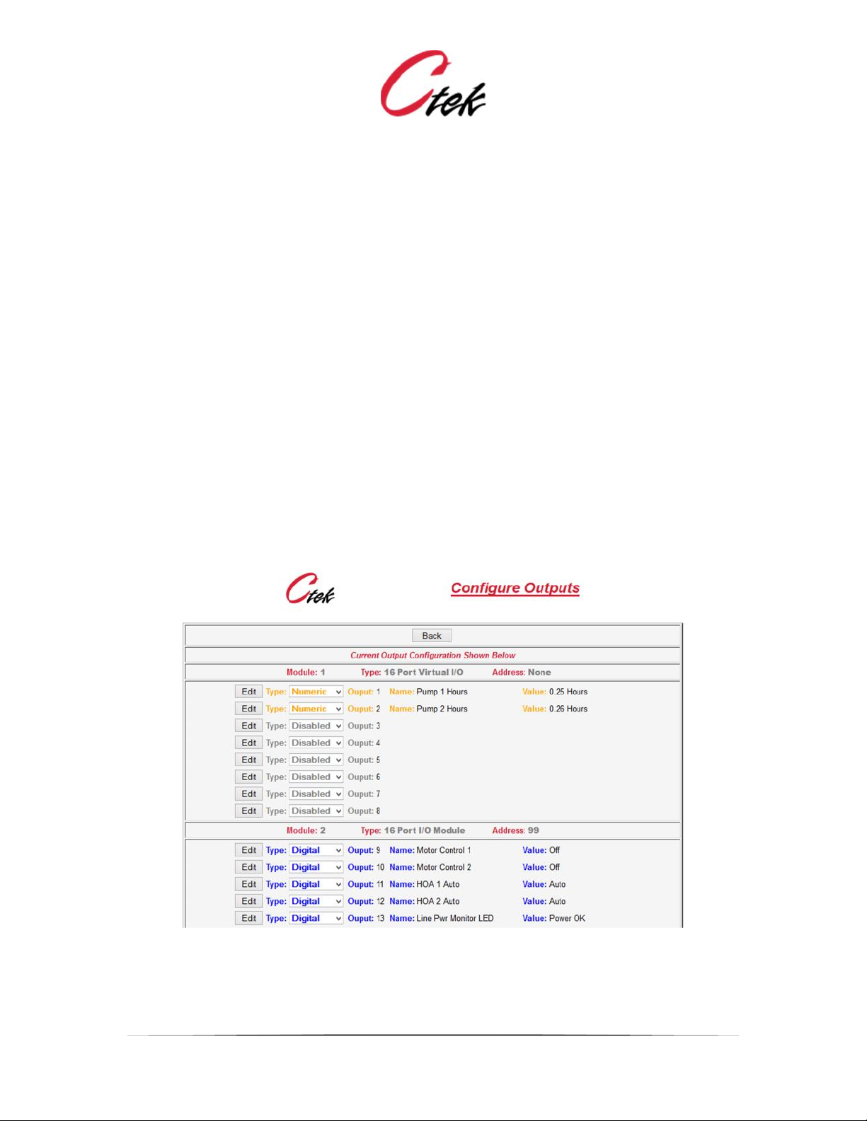
Configure Outputs
A representative portion of the Configure Outputs navigation screen is shown below. This is a
selection screen. Use the Type pull-down and Edit button to select a specific Output for edit. To
completely disable an output select Disabled in the pull-down and then press the associated edit
button.
The default display shows the current status of outputs across all modules. Output pins are
assigned numbers and displayed sequentially starting with the first module installed
Note: Output values are managed in one of four ways:
1. From the individual output's edit screen (output state field or current value + Submit)
2. By an On/Off button on the Control Panel
3. By the Shutoff Timer value on an output
4. Under program control by functions that are triggered by the threshold values of inputs
NOTE:
Each of these methods of changing an output state operates independent of the other, meaning
that one method might change the state of an output pin and another method could immediately
change it back. In other words an output manually turned on could be switched off by a threshold
when it is reached.
Figure 11 - Output Configuration Screen

Application Note – Automation Control Application
APN007 25 July, 2014
12
Output Configuration Screens
Figures 8 – 11 below show the configuration screens for the supported output types,
physical/digital, virtual/digital, and virtual/numeric. Following the screen images is a complete list
of attributes found on these screens and a description of their application on a specific type of pin.
Figure 12 Output - Physical/Digital
Figure 13 - Output Virtual/Digital

Application Note – Automation Control Application
APN007 25 July, 2014
13
Figure 14 - Output Virtual/Numeric

Application Note – Automation Control Application
APN007 25 July, 2014
14
Pin Name
Pin Type
Description
Output Name
All
Assigns a name to the output pin that will be
used in display, logging, and alarms
Local Display
All
Assigns the pin to a specific panel within the
control panel display. Set to Off for pins that
will not be displayed on control panel.
Note – Output pins assigned to the control
panel can be set to a value by a user. To
create a read-only display assign the output pin
to a virtual input pin and display the input pin.
Cloud Display
All
Defines which of 8 possible attributes this pins
value will appear on a SkyCloud pin
Log
All
When set to On changes in the state or value
of the output pin will be entered in the log file.
Note – See Logging Rules for more
information on logging
Program
All Virtual
The program name, selected from a pull down
of defined programs that will be executed when
a numeric or digital pin changes state or value.
Initial Value
All Digital
Specifies how the digital pin will be initialized
upon power up or restart. Choices are On, Off,
or Last. The Last setting will provide a
persistent pin value.
Label for On[Off]
All Digital
Provides labels for the state of a digital pin that
will be used on the control panel.
Output State
All Digital
Displays the current state of a digital output
pin. This value can be changed by the user,
causing the output to change state once the
Submit button is pressed.
Shutoff Timer
All Digital
Once a digital output has been set to On this
timer will return the pin to the Off state after a
specified number of seconds.
Polarity
Physical Digital
Inverts the physical state (open vs. conducting)
of a physical output pin relative to the logical
states of On or Off. In many cases UI
considerations will require that the labels for
On and Off be reversed to compensate for this
setting.
Decimal Scale
Virtual Numeric
Assigns levels of decimal precision to the value
represented by the output pin. Choices are 2
digits, 6 digits, or zero digits.
Current Value
Virtual Numeric
Much like the Output State setting for digital
pins this setting allows the user to change the
value stores on the numeric Input pin.
Initial Value (numeric)
Virtual Numeric
Specifies how the numeric pin will be initialized.
upon power up or restart. Choices are “Last
Value” or a user defined value
Figure 15 - Output Pin Definitions

Application Note – Automation Control Application
APN007 25 July, 2014
15
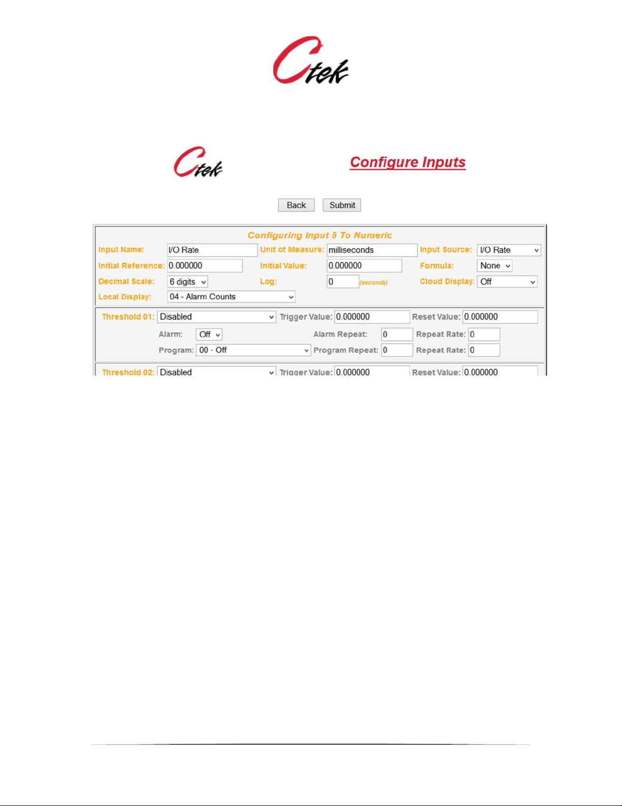
Configure Inputs
This is a selection screen. Use the Type pull-down and Edit button to select a specific Input for
edit. To completely disable an Input select Disabled in the pull-down and then press the
associated edit button.
The default display shows the current status of Inputs across all modules. Input pins are assigned
numbers and displayed sequentially starting with the first module installed
Note that the active individual inputs are color coded"
Purple = Analog Input
Green = Pulse Input
Blue = Digital Input
Figure 16 - Input Configuration Screen
Input Configuration Screens
Figures 8 – 11 below show the configuration screens for the supported Input types,
physical/digital, physical/analog, physical/pulse, virtual/digital, and virtual/numeric. Following the
screen images is a complete list of attributes found on these screens and a description of their
application on a specific type of pin.

Application Note – Automation Control Application
APN007 25 July, 2014
16
Figure 17- Input Physical/Digital
Figure 18 - Input Physical/Analog

Application Note – Automation Control Application
APN007 25 July, 2014
17
Figure 19 - Input Physical/Pulse
Figure 20 - Input Virtual/Digital
Application Note – Automation Control Application
APN007 25 July, 2014
18
Figure 21 - Input Virtual/Numeric

Application Note – Automation Control Application
APN007 25 July, 2014
19
Input Pin Name
Pin Type
Description
Key: PD = Physical Digital, PA = Physical Analog, PP = Physical Pulse VD = Virtual Digital, VN = Virtual Numeric VD = Virtual Digital, VN
= Virtual Numeric
Input Name
All
Assigns a name to the Input pin that will be used in display, logging, and alarms
Display
All
Assigns the pin to a specific panel within the control panel display. Set to Off for pins that
will not be displayed on control panel.
Note – Output pins assigned to the control panel can be set to a value by a user. To
create a read-only display assign the input pin to a virtual input pin and display the input
pin.
Cloud Display
All
Defines which of 8 possible attributes this pins value will appear on a SkyCloud pin
Log
All
Specifies in seconds the frequency at which the pins value will be logged. If set to zero (0)
logging on this pin is turned off.
Note – See Logging Rules for more information on logging
Initial Value
VD, VN
Specifies how the pin will be initialized upon power up or restart. Choices for digital are
On, Off, or Last. The Last setting will provide a persistent pin value. Numeric pins are set
to the value as specified.
Unit of Measure
PA, PP, VN
This field defines the units of measure to be used with the input, PSI or degrees for
instance. The control panel display will use this value in combination with the sensor
reading to create a display such as 27.3 PSI.
Threshold 1 – n
PA, PP, VN
Pull down field to define threshold type, Less Than or Greater Than and Edge Sensitive or
Level Sensitive.
Trigger Value
PA, PP, VN
The measured value at which the threshold will occur
Reset Value
PA, PP, VN
Sometimes referred to as the hysteresis band. The value associated with a trigger value
at which the threshold will be reset so that it can be triggered again. Example: If a level
sensor triggers at greater than 17 feet it might be assigned a reset value of less than 15
feet. Once the level was sensed at 17 feet the tank level would have to return to 15 feet
before another 17 foot event could be triggered. The zone between trigger and reset
eliminates multiple alarms if the value is oscillating at approximately the trigger point.

Application Note – Automation Control Application
APN007 25 July, 2014
20
Alarm
PA, PP, VN
On/Off for SMS and email Alarms associated with a specific threshold
Alarm Repeat
PA, PP, VN
The number of times that an alarm for a single threshold will be repeated. A value of zero
(0) will allow only one alarm to occur.
Repeat Rate
PA, PP, VN
The interval in minutes between alarms when a repeat value is set.
Program
PA, PP, VN
The program name, selected from a pull down of defined programs that will be executed
when a threshold is reached.
Program Repeat
PA, PP, VN
The number of times that an program for a single threshold will be run. A value of zero (0)
will allow only one program execution to occur. A value of 9999 will cause the program to
execute perpetually at the repeat rate.
Repeat Rate (program)
PA, PP, VN
The interval in minutes between program executions when a repeat value is set.
Formula
PA, VN
The numeric ID of a formula assigned to this input. In most cases formula 1 (standard
input formula) will be assigned.
Polarity
PD, VD
Establishes the input level that will indicate On and Off. Choices are 0=Off or 0=On.
Label For On[Off]
PD, VD
Provides labels for the state of a digital pin that will be used on the control panel.
Input Source
(Digital)
PD, VD
Identifies the source(s) that will be used to define the state of a digital input. The state of
multiple pins can be combined using Boolean to arrive at a final state. Also, digital events
occurring on the SkyRouter platform can be assigned as part or all of a pin’s value. See
digital input sources table below.
On[Off] Alarm
PD, VD
On/Off for SMS and email Alarms associated with the On state and the Off state of a
digital input.
On[Off] Alarm Repeat
PD, VD
The number of times that an alarm for a single state will be repeated. A value of zero (0)
will allow only one alarm to occur.
On[Off] Repeat Rate
PD, VD
The interval in minutes between alarms when a repeat value is set.
On[Off] Program
PD, VD
The program name, selected from a pull down of defined programs that will be executed
when the state (On/Off) is reached.
On[Off] Program
Repeat
PD, VD
The number of times that an program for a state will be run. A value of zero (0) will allow
only one program execution to occur. A value of 9999 will cause the program to execute
perpetually at the repeat rate.
On[Off] Repeat Rate
PD, VD
The interval in minutes between program executions when a repeat value is set.
Min[Max] Range
PA
Range refers to the range or precision of the analog to digital (A/D) conversion. Ctek 1216
I/O modules provide 12 bit conversion resulting in a theoretical 4096 discrete values, 0 -
4095. Ctek I/O modules start with a range offset of 7 making the theoretical available
range 7 - 4095. Once the sensor is calibrated the actual available range may be

Application Note – Automation Control Application
APN007 25 July, 2014
21
somewhat smaller than the theoretical due to sensor characteristics and minor variations
in the reference voltage.
Min[Max] Units
PA
This is a quantitative value for the low end of the expected engineering value
measurement of this sensor. For example for a temperature sensor that is designed to
measure between 10° and 300° the minimum Units would be 10, the Max Units would be
300, and the Units of Measure would be degrees.
Correction
PA
A specific correction or offset for this input. This can be used to correct for minor
variations in sensors that cannot be corrected in a common input formula.
Multiplier
PP
The value of an individual pulse. For example, if the multiplier value is for a gallons per
minute calculation is 10 each pulse will be counted as 10 gallons and the value (10 *
number of pulses * 60) would yield a gallons per minute value.
Interval
PP
The time interval in seconds to be used in scaling the pulse input for control panel output.
For instance, an input measured in gallons per minute (GPM) would use an interval of 60
seconds (1 minute) to scale the input.
Input Source
(Numeric)
VN
Identifies the source(s) that will be used to define the state of a virtual numeric input. The
value of other input pins or virtual output pins can be assigned through this setting. Also,
numeric events occurring on the SkyRouter platform can be assigned as a pin’s value.
Examples of the later would be RSSI or Latitude. See table of Numeric Input sources
below.
Initial Reference
(Numeric)
PA, PP, VN
The initial reference is the first value that a numeric or analog pin will be compared to after
a power up or execute new configuration. The initialization comparison will be made
against the Initial Value (see next) which is assigned to a pin during the start up. Alarms
are not issued during the initialization comparison but program actions will occur. This
provides a starting point (usually at one of the extremes) for evaluating the pin against
actual values once the initialization has completed which in turn provides a method of
conditioning the managed machines or devices to a quiescent state before normal
operation begins.
Initial Value
(Numeric)
PA, PP, VN
The initial value that will be assigned to a pin for comparison during the initialization
(power up) phase. See Initial Reference above.
Decimal Scale
VN
Assigns levels of decimal precision to the value represented by the virtual numeric input
pin. Choices are 2 digits, 6 digits, or zero digits.
Figure 22 - Input Pin Definitions

Application Note – Automation Control Application
APN007 25 July, 2014
22
Digital Input Pins – Source of Inputs
Figure 23 - Input Sources (Digital)
Digital input pins can receive inputs from themselves, any other digital input or output pin, or the
following internal sources listed in the table below. Up to four input sources can be combined
using the boolean operator AND or the boolean operator OR. All input processing is completed
before the pin is evaluated.
Input Definitions – Virtual Digital Inputs
Input Pins
Any Input pin (physical or virtual)
*
Output Pins
Any Output pin (physical or virtual)
*
Relay In
Reflects the state of the relay input contact
(discrete input) that is available on the
SkyRouter platform
GPS Status
Reflects the state of the internal GPS receiver
as shown on the Navigation Unit Configuration
Screen. 1 = OK; 0 = GPS unavailable
WWAN Status
Reflects the state of the Wireless WAN as
reflected on the Wireless Configuration Screen.
1 = Enabled; 0 = Disabled
* Caution – Be sure that pins assigned to other pins are of the same type. Example: Analog to
numeric is OK but Analog to Digital will yield unpredictable results.
Figure 24 - Input Sources (Digital Virtual)

Application Note – Automation Control Application
APN007 25 July, 2014
23
Numeric Input Pins – Source of Inputs
Figure 25 - Input Sources Numeric
Analog or numeric input pins can receive inputs from themselves, any other numeric input or
output pin, or the following internal sources listed in the table below. A formula assigned to a pin
will be processed before the pin is evaluated.

Application Note – Automation Control Application
APN007 25 July, 2014
24
Input Definitions – Virtual Numeric Inputs
Input Pins
Any Physical or Virtual Input pin
*
Output Pins
Any Physical or Virtual pin
*
Voltage In
Input voltage to the SkyRouter
Temp Cent
Internal Temperature of SkyRouter - C
Temp Farn
Internal Temperature of SkyRouter - F
WWAN RSSI
Signal Strength of cellular signal
GPS LAT
Latitude measured by internal GPS
GPS LON
Longitude measured by internal GPS
GPS Speed
Speed measured by internal GPS
GPS Course
Course measured by internal GPS
Sys Errors
System error count as senses by Automation
Control
Time Hr
The current hour reflected in the 24 hour
system clock
Time Min
The current minute reflected in the 24 hour
system clock
Time Hr:Min
The current hours and minutes reflected in the
system clock. Provides a complete 24 hour
clock value.
I/O – Rate
The rate in milliseconds at which all connected
I/O module pins are being scanned and set.
This time represents the time required to
completely process inputs and outputs on all
connected I/O modules.
* Caution – Be sure that pins assigned to other pins are of the same type. Example: Analog to
numeric is OK but Analog to Digital will yield unpredictable results.
Figure 26 - Input Definitions (Numeric)
More About Digital Inputs and Outputs
Understanding The Input and Output Polarity Setting
A digital input pin is evaluated as a 1 or 0 (On or Off, True or False) solely on the voltage level
present at the input pin, or in the case of a virtual pin the value (1 or 0) assigned to it from another
input, output, or program. Simply stated a digital input having greater than 4 volts present on it will
be evaluated as a 1 and that same pin will evaluate to 0 if its input voltage is less than 1 volt.
The polarity setting on an input does not affect the way the pin is evaluated. Instead, the polarity
setting inverts the logic (On or Off) that determines which program will run and if an alarm will be
issued.
In the case of a digital output the On state indicates that pin is conducting (sinking current) and
the Off state is when the pin is not conducting. Polarity selection for an output reverses the logic
that will cause a pin to turn on.

Application Note – Automation Control Application
APN007 25 July, 2014
25
Min/Max Range and Sensor Calibration:
Range refers to the range or precision of the analog to digital (A/D) conversion. Ctek 1216 I/O
modules provide 12 bit conversion resulting in a theoretical 4096 discrete values, 0 - 4095. Ctek
I/O modules start with a range offset of 7 making the theoretical available range 7 - 4095. Once
the sensor is calibrated the actual available range may be somewhat smaller than the theoretical
due to sensor characteristics and minor variations in the reference voltage.
Calibrating an Analog sensor - The Min and Max range fields can be used to
automatically calibrate the sensor. To perform calibration the sensor must be powered up
and properly configured within the Automation Control application. Once the sensor is
configured the application automatically records the extremes (high/low) values for the
sensor. Some sensors have a built in calibration feature. In that case select the minimum
(low) level calibration on the sensor and leave it in that position for at least 10 seconds.
Repeat this process for the high or maximum value, again waiting at least 10 seconds.
If the sensor does not have an internal calibration feature there are two possible
approaches to calibration. First, consult the sensor vendor's literature. The vendor will
certainly define the Min and Max units that the sensor is defined for, for instance -30 to
+70 degrees. Also, it is common for the specifications to indicate a minimum and
maximum output of the sensor at a specified reference voltage. Those values can be
used to trim the Min and Max range inputs for the sensor. As an example, if a sensor is
specified to output 0.25 volts on the low end of the scale for a reference voltage of 5 volts
that would equate to 5% (0.25 / 5.00) of the total range which would make the Min Range
equal to 205 (4095 * 0.05) and the Max Range equal to 3890.
An internal calibration feature is also available that analyzes the actual reference values
available on the module. To use this feature the input pin is connected to the I/O modules
ground for 10 seconds followed by connecting the input pin to the sensors reference
voltage for 10 seconds. Once the input pin has been exposed to the extremes for 10
seconds each simply enter an asterisk (*) character in the MIN and Max range fields and
press submit. The asterisk characters will be replaced with the Min and Max range values
sensed during the calibration process.

Application Note – Automation Control Application
APN007 25 July, 2014
26
Analog Input Processing
Figure 27 - Analog Input Processing
Thresholds
There are three key concepts to understand about thresholds. The first is to recognize that
thresholds have a directional component, meaning that each threshold is defined in terms of a
less than or greater than modifier. A Less than threshold only triggers (causes an action) when
the measured value is decreasing, and a greater than thresholds only triggers when the
measured value is increasing. Although thresholds only trigger in their defined (less than/greater
than) direction they are logged in both directions to create a complete record of events.
The second key concept is that thresholds have a temporal (time sensitive) component that is
defined by level sensitive or edge sensitive. A level sensitive threshold is based on the
currently measured value. A level sensitive threshold is state (current status) driven. For example,
less than 10 feet level sensitive is true for an input that is currently at 9.5 feet and had
previously come from a level greater than 10 feet. If a lower threshold, say less than 6 feet level
sensitive is also defined programs (actions) associated with the less than 6 feet level sensitive
threshold will occur once that level is reached.
Edge sensitive thresholds are event driven. They mark events that have occurred in a defined
direction. For instance, the event less than 8 feet edge sensitive will occur as the measured
value decreases from the 10 foot level to the 6 foot level. Because the less than 8 feet edge
sensitive threshold is event driven any action (program) assigned to the event will occur as the
transition through less than 8 feet is achieved without regard to any level sensitive thresholds
that may be in effect. One practical application of edge sensitive thresholds is to mark the

Application Note – Automation Control Application
APN007 25 July, 2014
27
boundaries of an operating range that would otherwise be in conflict with level sensitive
thresholds. The diagram and tutorial following demonstrates this application.
The last key concept is the order in which thresholds are evaluated. This is critical because
thresholds MUST be defined on the input screen in the order that they will be evaluated. In MOST
cases this means that the smallest value to be considered must be on the first threshold line of
the input edit screen and that the largest value to be considered must be on the last line of the
input edit screen. Values between the largest and the smallest should be entered in increasing
value from the top.
Thresholds – An Example
Figure 18 shows a simple example of an application designed to keep a tank level between 2 and
8 feet. As the tank level rises past eight feet pump #1 and the level light come on. If the tank level
continues to rise past fifteen feet pump #2 is started. At the eighteen foot level an alarm is issued.
As the tank is pumped down a below eight feet the level light is turned off and at the two foot level
both pumps are turned off.
The eight foot decreasing level edge triggered threshold demonstrates one application of edge
triggering. The requirement is to both turn the light on and turn it off at the eight foot level. Clearly
these two things would be in conflict if level sensitive thresholds were used. However, because
the light is on at any level above 8 feet and turned off on any transition below eight feet this
requirement can be met.
Figure 28 - Threshold and Direction

Application Note – Automation Control Application
APN007 25 July, 2014
28
Pulse Input - Latching
The setting Greater Than Latch Function is a special case unique to the pulse input. It is
designed to be used to capture and execute upon single pulse type inputs that have the
possibility of recurring. A typical use of this type of input is to capture (latch) the depression of a
momentary switch. When set with a value of 0.00 it will launch its assigned program each time
the switch is pressed to cause a pulse.
Application Note – Automation Control Application
APN007 25 July, 2014
29
Configure Formulas
Ctek's Automation Control application provides support for user defined formulas that can be
applied to analog and numeric inputs. Formulas are applied as a part of the input processing prior
to the pin being evaluated.
A standard conversion formula is released with the firmware. In many cases this standard formula
will suffice for input processing. Users may create additional formulas using postfix notation, an
input format colloquially known as RPN or Reverse Polish Notation.
[NB. Reverse Polish pays homage to the nationality of logician Jan Łukasiewicz, who
invented (prefix) Polish notation in the 1920s. The antithesis of prefix (Polish) notation is
postfix (reverse Polish) notation.]
A simple albeit useful explanation of postfix (RPN) notation is that it is a mathematical notation
wherein every operator follows all of its operands. As an example 2 [Enter] 5 [Multiply] = 10. The
result, 10 is then pushed on the top of the stack where it becomes the next operand in line.
Therefore, 2 [Enter] 5 [Multiply] = 10 and 2 [Enter] 5 [Multiply] 7 [Multiply] = 70.
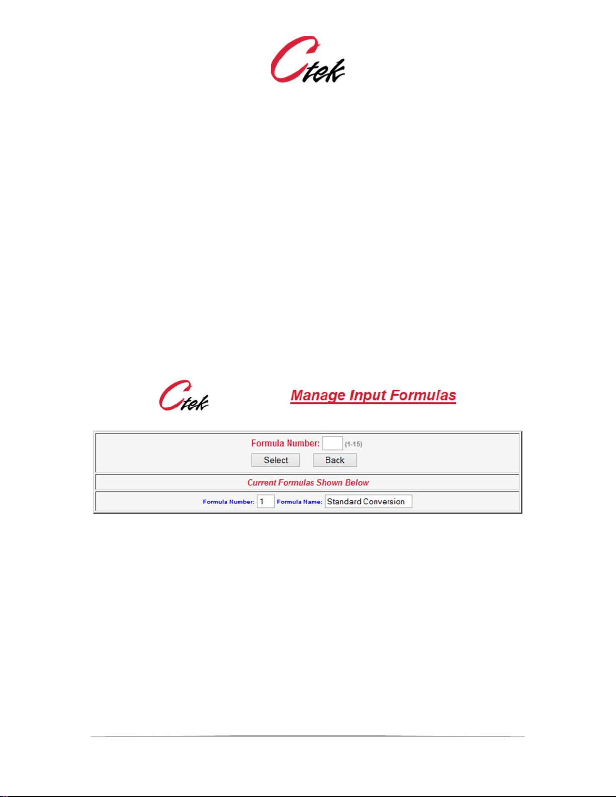
From the top level Automation Control Configuration menu selecting Formulas presents the
following selection screen which allows a user to select an existing formula for modification or
create a new formula by entering an unused formula number.
Figure 29 - Input Formula Selection Screen
Selecting a new or existing formula for edit brings up the following screen. The left hand column
provides a selection of pull-down operands. The right hand column provides a pull down selection
of operators. Constants are entered in the center column. An explanation of field selection
follows.

Application Note – Automation Control Application
APN007 25 July, 2014
30
Figure 30 - Edit Input Formula
Operands
Current Input Pin:
Selects the input value provided by the pin to which the formula is attached as an operand
Other Input Pin:
Selects the value on the input pin referenced in the right hand column
Output Pin =
Selects the value on the output pin referenced in the right hand column
Constant Value =
Use the constant entered in the center column as the next operand
Correction:
The correction value associated with this input becomes the next operand
Min Range:
The minimum range value associated with this input becomes the next operand
Max Range:
The maximum range value associated with this input becomes the next operand
Max – Min Range
The value (Maximum Range - Minimum Range) becomes the next operand
Min Units:
The minimum units value associated with this input becomes the next operand
Max Units:
The maximum units value associated with this input becomes the next operand

Application Note – Automation Control Application
APN007 25 July, 2014
31
Max – Min Units:
The value (Maximum Units - Minimum Units) becomes the next operand
(fn) Average Memory 1 and (fn) Average Memory 2
Both functions do the same thing but each can only be used by one pin so the 2 environments
allow for a total of 2 averaging inputs. These are functions are performed on the value in the X
register with the results being returned to the X register. Just like on a calculator when you have a
value on the screen and you hit a function key like square root. This means that operator field
(Ent, Sub, Add, etc.) is optional if the function is the last step in a formula. However, if it is an
intermediate step you can use an operator on the average value or push it on the stack (Ent) for
further calculations. The variable field of the formula step must contain a value between 1 and
100 indicating how many samples should be averaged. During the first N samples (1 – 100 as
defined in the formula) a value of zero will be returned. Once N samples have been processed, a
new average value, based on the last N samples will be returned with each execution of the
function.
Operators
Ent
Enter the defined operands value
Sub
Subtract
Add
Add
Mul
Multiply
Div
Divide
Xch
Exchange the current operand with the previous one
An explanation of the standard conversion formula
The standard formula is releases with the Automation Control application. In many cases it will
provide all of the input processing required. The standard conversion formula is shown below on
the edit screen. An explanation follows.

Application Note – Automation Control Application
APN007 25 July, 2014
32
Figure 31 - Standard Conversion Formula
The standard conversion formula shown above reads the sensors input value and subtracts from
it the minimum range value assigned to the sensor. It then divides the resulting value by the value
of (Max - Min Range). The resulting number is then multiplied by the value of (Max - Min Units)
and also by the correction value assigned. Lastly the value of Minimum Units is added to the
result of all of the preceding operations. This final value will be displayed in the Value field of the
Input screen and on the control panel. As a practical example assume that a 0 - 10 amp current
sensor is installed and when calibrated it has a range of 7 - 4090. The following configuration
would be made on that sensor's Input settings.
Min Range - 7
Max Range - 4090
Min Units 0.00
Max Units - 10.0
Correction Factor 1.0
Unit of Measure - Amps
Sensor value (when read) = 2037
The standard conversion formula would do the following:
Read the sensor (2037) and subtract from it the Min Range (7) resulting in 2030
Divide the result by the value of (Max Range - Min Range) resulting in 0.4972
Multiply by Max Units - Min Units (10 - 0.0) resulting in 4.972
Multiply by correction factor (1.0) resulting in 4.972
Add the value of Min Units (0.00) resulting in 4.972
The Unit of measure (Amps) would then be appended to the calculated value resulting in a
display of 4.97 Amps on the Input screen and the Control Panel.

Application Note – Automation Control Application
APN007 25 July, 2014
33
Programs
Programs are named groups of functions that can be applied to a specific input or output as the
result of a threshold event or level occurring on an input or virtual output. For instance, a program
called Power Indicator OFF (9) could be used to turn on an indicator whenever charging power
is removed from a battery powered system. The same program could also set the application
status to yellow or 1 for display on VDDNS. Programs are assigned names that are made
available in the program pull-down field of the input and virtual output edit screens. To create,
modify, or delete a program select the Program option on the main menu screen. The following
selection screen will be shown.
Figure 32 – Program Select
To view, modify, or delete an existing program select a program number from the display menu.
To create new programs enter a program number that does not currently exist into the selection
field. When a program is displayed, it will appear as in Figure 32 below.

Application Note – Automation Control Application
APN007 25 July, 2014
34
Figure 33 – Program Edit Screen
Program Edit Fields
Program Name
The user defined name assigned to this program
Action
The action field provides a pull-down menu of the different functions that can be executed by this
program.
Parameters
The parameters field contains values that the program will operate upon. Parameters MUST be
space separated.
Function Library
A complete list of functions and associated parameters is found in Appendix A.

Application Note – Automation Control Application
APN007 25 July, 2014
35
Log and Logging
Set Up and Management
The Automation Control application maintains a log file of events and thresholds in near real time
as they occur. Logging is enabled on the unit configuration screen. The unit configuration also
allows the user to specify the frequency at which they wish to receive log files and the frequency
at which events will be logged.
If enabled the log is transmitted to one or more email recipients based on the schedule defined in
the unit configuration screen. The log is also available for online viewing from the Automation
Control menu.
The log file transmitted by email is formatted as a comma separated (CSV) file. It can be read
and manipulated on your desktop using standard spreadsheet applications. Many database
applications can also import CSV files. When the log is emailed to designated recipients the log
information from the previous interval is left on the SkyRouter for online viewing. As an example,
if the log is sent every day one day’s information is left online. If the log is sent every other day
two days information remains on the system.
Logging Rules
Each output has a pull down to enable or disable logging. Input pins have a logging field that
allows the user to specify in seconds the frequency at which the pin will be logged.The rules
governing when events are logged are as follows:
Digital Inputs
Digital Inputs are logged each time they change state and every logging interval as defined on the
individual input’s set-up screen.
Analog, Pulse, and Numeric Inputs
Analog, Pulse, and Numeric inputs are logged whenever a defined threshold is reached and
every logging interval as defined on the individual input’s set-up screen.
Digital Outputs
Digital Outputs are logged each time they change state.
Numeric Outputs
Numeric Outputs are logged each time that the value changes.

Application Note – Automation Control Application
APN007 25 July, 2014
36
The Control Panel
The Control Panel for the Automation Control provides a consolidated view of selected inputs and
outputs that have been selected for display in their specific configuration. The control panel also
provides On/Off buttons for digital outputs and a data entry field for numeric outputs. Inputs are
always displayed as read only..
The Control Panel is accessible from the SkyRouter's top level menu at the same level as the
general administration menu. It can also be accessed from applications category under the
general administration menu.
Figure 34 - Control Panel Selection at Login
Provisioning the Control Panel
After the input and output configurations have been the new settings are deployed by returning to
the top level configuration menu (Figure 3) and pressing the Execute New Configuration button.
There will be a brief delay will all of the input and output settings are deployed and all of the
inputs read. This activity will also create a new Control Panel display. An example of a Control
Panel is shown below.

Application Note – Automation Control Application
APN007 25 July, 2014
37
Figure 35 - Sample Control Panel Display

Application Note – Automation Control Application
APN007 25 July, 2014
38
Appendix A – Function Library
Functions are predefined building blocks used to build user defined programs. Parameters or
arguments to the functions must be separated by a single space.
The following is the current list of functions available for creating user programs: Following the
function list is a detailed description of each individual function.
Function List
Digital I/O – Set
Numeric I/O – Set
Numeric I/O – Add
Numeric I/O – Subtract
Numeric I/O – Multiply
Numeric I/O – Divide
Remote I/O - Set
Timer/Counter – Start
Timer/Watchdog – Start
Timer/Clock – Start
Timer/Counter/Ext/Clk – Start
Timer/Alarm Override - Start
Timer/Any – Stop
Motor Group Control
Application Status – Set
Input Threshold – Set
Execute New Configuration
Function Descriptions
Digital I/O – Set
Digital I/O – Set P1 P2 P3 P4
P1 and P2 define the destination that is being set while P3 and P4 define the source. Use user
defined value 1 to set a pin and user defined 0 to reset a pin.
P1 = i for input or o for output (must be digital)
P2 = pin number (must be digital)
P3 = i for input, o for output or u for user defined value
P4 = pin number or user defined value
Example: Setting digital output pin 6 to On (1)
Action = Digital I/O – Set

Application Note – Automation Control Application
APN007 25 July, 2014
39
Parameters = o 6 u 1
Numeric I/O – Set
Numeric I/O – Set P1 P2 P3 P4
P1 and P2 define the destination that is being set while P3 and P4 define the source
P1 = i for input or o for output (Must be numeric)
P2 = pin number (Must be numeric)
P3 = i for input, o for output or u for user defined value
P4 = pin number or user defined value
Example: Setting numeric input pin 12 to the value of numeric output pin 9
Action: Numeric I/O – Set
Parameters: i 12 o 9
Math functions
Numeric I/O – Add P1 P2 P3 P4
Numeric I/O – Subtract P1 P2 P3 P4
Numeric I/O – Multiply P1 P2 P3 P4
Numeric I/O – Divide P1 P2 P3 P4
P1 and P2 define the destination that is being set while P3 and P4 define the source
P1 = i for input or o for output (numeric)
P2 = pin number (numeric)
P3 = i for input, o for output or u for user defined value
P4 = pin number or user defined value
Example: Add 1200.77 to input pin 17 and place the result on output pin 17
Action: Numeric I/O – Add
Parameter: o 17 u 1200.77
Example: Multiple input pin 14 by input pin 15 and place the result on input pin 14
Action: Numeric I/O – Multiply
Parameter: i 14 i 15

Application Note – Automation Control Application
APN007 25 July, 2014
40
Note on Remote Commands
Remote operations are those decisions and resulting actions that are distributed between two or
more SkyRouters in different physical locations connected over the cellular network. This release
contains a significant simplification of remote operations. Now all remote operations are reduced
to a single function providing the ability to remotely set the values of remote virtual input pins and
all types of output pins, both physical and virtual. This approach allows decisions to be made at
the site where the actually machinery will be turned on and off and therefore provides a higher
degree of reliability since the On/Off decisions have built-in retry capabilities.
Remote I/O - Set
Remote I/O - Set P1 P2 P3 P4 P5 P6
P1, P2 and P3 define the remote destination that is being set while P4 and P5 define the local
source
P1 = iP address of destination
P2 = i for input or o for output
P3 = pin number
P4 = i for input, o for output or u for user defined value
P5 = pin number or user defined value
P6 = net wait.
a) If P6 = 1 causes the remote operation to wait for a certain period of time for the
SkyRouter to get an IP address from the network.
b) If P6 = 0, do not wait for network. Instead simply assume that the network is available
and initiate the remote operation which will succeed if an address is available or fail if it is
not.
Example: Set a input pin 24 of IP address 166.155.12.12 to 1 after waiting for the network to
respond
Action: Remote I/O - Set
Parameters: 166.155.12.12 i 24 u 1 1
Example: Set output pin 18 at IP address 173.101.15.44 to the value of local input pin 4 without
waiting for the network
Action: Remote I/O - Set
Parameters: 173.101.15.44 o 18 i 4 0
Note On Timer/Counter
Timer/Counter is a value incrementing or decrementing at one second intervals. It is housed on a
numeric input or numeric output. If it is in an output it is non-volatile and if it is in an input it is
volatile. If it is in an output, the output can still be connected to an input. In either case the
thresholds of an input can then be used to make decisions based on the counter value or the
value can just be used to accumulate things like engine hours.

Application Note – Automation Control Application
APN007 25 July, 2014
41
Timer/Counter – Start [Note – Changed In Release 4.02.02]
Timer/Counter – Start P1 P2 P3 P4 P5 P6 P7 P8 P9
P1 = i for input or o for output (numeric)
P2 = pin number. This is where the timer value lives (numeric)
P3 = counter type. 0 = count up from current value, 1 = count up from user/pin defined value, 2 =
count down from current value, 3 = count down from user/pin defined value
P4 = i for input, o for output or u for user defined value
P5 = pin number or user defined starting value
P6 = limit type. 0 = no limit, 1 = stop at user defined limit, 2 = roll over to start value at user
defined limit and continue counting
P7 = limit value for P5 mode 1 and 2 (numeric)
P8 = update value (float). How much to add or subtract at the end of each second.
P9 = write rate in 1 second increments. How often to write timer value to selected input or output
pin (numeric)
Example – Create a counter on output pin 14 that counts up from 0 to infinity in seconds and
updates the display every 15 seconds
Action: Timer/Counter – Start
Parameters: o 14 0 u 0 0 0 1 15
Timer/Watchdog – Start [Note – Changed In Release 4.02.02]
A watchdog timer is a value decrementing at a one second rate. The value is NOT directly
housed in an input or output pin. When the value decrements to zero the defined digital output or
input pin will turn on. If you keep setting the watchdog timer, it will never get to zero.
Timer/Watchdog – Start P1 P2 P3 P4 P5
P1 = i for input or o for output (digital)
P2 = pin number. This is the pin that will go high when the watchdog expires (digital)
P3 = i for input, o for output or u for user defined value
P4 = pin number or user defined starting value
P5 = update value (float). How much will be subtracted from the timer each second.
Example – Set output pin 4 when a 60 second timer reaches 0.
Action: Timer/Watchdog – Start
Parameters: o 4 u 60 1
Timer/Clock – Start [Note – Changed In Release 4.02.02]
A clock is a square wave signal generated on an input or output. It can be continuous or of a pre-
defined pulse length. The clock frequency is generated by a decrementing counter. Each time the
counter decrements to zero, the defined digital input or output will toggle state.

Application Note – Automation Control Application
APN007 25 July, 2014
42
Timer/Clock – Start P1 P2 P3 P4 P5 P6 P7
P1 = i for input or o for output (digital)
P2 = pin number. This is where the clock is generated (digital)
P3 = i for input, o for output or u for user defined value
P4 = pin number or user defined clock rate value
P5 = update rate (int) in 0.1 second increments. How often start value will be decremented.
P6 = update value (float). How much will be decremented from P4 for each update period.
P7 = stop value. Stop clock after this many pulses. If P6 is zero, clock is continuous.
Example – Clock output pin 1 at a rate of once every 1 second (1 seconds On followed by 1
seconds Off) for 400 iterations
Action: Timer/Clock – Start
Parameters: o 1 u 5 10 1 400
Timer/Counter/Ext/Clk – Start [Note – Changed In Release 4.02.02]
Note: The input value being counted in this function is coming from the Discrete or Relay input
of the SkyRouter.
Timer/Counter/Ext/Clk is a value incrementing or decrementing at the rate of the Discrete Input
(DI) pin on the SkyRouter, also known as the relay input. The Timer/Counter is assigned to a
numeric input or numeric output. If it is in an output it is non-volatile and if it is in an input it is
volatile. If it is in an output, the output can still be connected to an input. In either case the
thresholds of an input can then be used to make decisions based on the counter value or the
value can just be used to accumulate things like engine hours.
Timer/Counter/Ext/Clk - Start P1 P2 P3 P4 P5 P6 P7 P8 P9 P10
P1 = i for input or o for output (numeric)
P2 = pin number. This is where the timer value lives (numeric)
P3 = counter type. 0 = count up from current value, 1 = count up from user defined value, 2 =
count down from current value, 3 = count down from user defined value
P4 = i for input, o for output or u for user defined value (counter types 1 & 3)
P5 = pin number or user defined starting value
P6 = limit type. 0 = no limit, 1 = stop at user defined limit, 2 = roll over to start value at user
defined limit and continue counting
P7 = limit value for P5 mode 1 and 2 (float)
P8 = update value (float). How much to add or subtract at each input transition.
P9 = write rate in 1 second increments. How often to write timer value to selected input or output
pin (int)
P10 = sample type. 0 = count negative going transitions. 1 = count positive going transitions.
Example – Count negative going transitions of the Discrete Input and place the count on output
pin 17. The counter should count up from zero and has no limits. For each transition of the
Discrete Input add 15 to the value of pin 17. Pin 17 will be updated every 30 seconds.
Action: Timer/Counter/Ext/Clk - Start
Parameters: o 17 1 u 0 0 0 15 30 0

Application Note – Automation Control Application
APN007 25 July, 2014
43
Timer/Alarm Override – Start [Note – Changed In Release 4.02.02]
cP1 P2 P3 P4
Timer/Alarm Override – Start provides a mechanism to override (disable) all alarms for a
specified (in minutes) period of time. P1 and P2 define the pin that will represent the state of
override, and P3 and P4 define the period of time for which alarms will be disabled.
As with all timers Timer/Alarm Override is stopped with Timer/Any - Stop
P1 = i for input or o for output (numeric)
P2 = pin number. This is where override condition is represented – Use this pin in Stop command
P3 = i for input, o for output or u for user defined value of override duration in minutes
P4 = pin number or user defined override duration value
Example: Disable alarms for the number of minutes specified by input pin 11 and show override
status on output pin 18.
Action: Timer/Alarm Override – Start
Parameters: o 18 i 11
Timer/Any – Stop
This will stop any class of Timer shown above.
Timer/Any – Stop P1 P2
P1 = i for input or o for output
P2 = pin number
Example – Stop a time previously started on output pin 5
Action: Timer/Any – Stop
Parameters: o 5
Important Notes on Motor Group Control
a) Parameters P3 (Outputs), P4 (Inputs), and P5 (Outputs) require sequential assignment
starting at the pin specified for the number of elements in the sequence. For example, a
controller having 3 pumps might assign output pin 12 to be the starting pin for the first
motor. This would automatically require that output pins 13 and 14 be the starting pins for
motors 2 and 3 respectively.
b) All motor control outputs (defined by P3) must be configured so that their initial state is
set to zero during automation control start up.
c) All override pins (defined by P4) must be configured to execute override_state_change
function when override pin turns on or off. This means that override_state_change must
be defined as both the “Off Program” and “On Program” on all override pins.

Application Note – Automation Control Application
APN007 25 July, 2014
44
d) All hour timers (defined by P5) must be housed in outputs. The value of P5 will be
interpreted as an output.
Motor Group Control
Allows up to four motors to be controlled in a group where primary responsibility will alternate to
ensure wear leveling. Hours of operation will be tracked in hours and tenths of hours.
Motor Group Control – P1 P2 P3 P4 P5
P1 = function:
start_primary 1
start_secondary 2
start_tertiary 3
start_quaternary 4
start_all 5
stop_primary 6
stop_secondary 7
stop_tertiary 8
stop_quaternary 9
stop_all 10
override_state_change 11
P2 = motor_count: how many motors in this group (1 - 4)
P3 = motor_start: Starting output pin for motors. Others will be assigned sequentially
P4 = override_start: Starting input pin for override control of motor. Others will be assigned
sequentially.
P5 = hours_start: Starting output pin for hour meters. Others will be assigned sequentially.
Note: Override (P4) refers to a switch or signal to place the motor in service or take it out of
service. When the motor is in service it operates automatically under the control of the
Control_Motor_Group function. When it is out of service it is not available as a part of the
group being controlled. A motor that is out of service can still be switched on and off
manually but its state will be unknown to the Control_Motor_Group function.
Example – Starting the primary pump at a pump station with two pumps starting on output pin 2
that are managed by override switches starting at input 4 and whose hours are tracked on
outputs starting at output 6.
Action: Motor Group Control
Parameters: 1 2 2 4 6
Example – Stopping all pumps at a pump station with two pumps starting on output pin 2 that are
managed by override switches starting at input 4 and whose hours are tracked on outputs starting
at output 6.
Action: Motor Group Control
Parameters: 10 2 2 4 6

Application Note – Automation Control Application
APN007 25 July, 2014
45
Application Status – Set [Note – New In Release 4.02.02]
Application Status – Set provides a queuing and prioritization mechanism for Automation Control
events/thresholds/states (Alarm States) that wish to change the application status color of the pin
indicating the units position on the SkyCloud display. Between 1 and 10 different pins, each
capable of changing the display to red, yellow, or green can be managed.
The prioritization mechanism insures that any red condition has the highest priority, followed by
any yellow condition. The application status can only be green if no red or yellow inputs are being
processed.
Important – The Application Status – Set mechanism requires that the number of events capable
of producing an alarm state be defined. It also requires that each alarm event report its status
once before the first application status change will be issued to SkyCloud. In terms of
implementation this means that each alarm event must have a corresponding alarm-clear event.
The alarm-clear event should update Application Status – Set with a green status. Specifically, for
a digital pin there needs to be a function with a program assigned to both the On and Off states of
the pin, and for a analog/numeric pin there needs to be both an alarming threshold and a
corresponding alarm clear threshold. In short both an Alarm and an Alarm-Clear needs to be
assigned to each pin that can generate an alarm.
Application Status – Set P1 P2 P3 P4
P1 = Alarm Point ID – A unique number between 1 and 10 that identifies an alarm point (pin) in
an Automation Application. As an example a switch might be 1 and a temperature sensor might
be 2.
P2 = Status – The value that this specific alarm point is setting. Valid values are:
0 – Green
1 – Yellow
2 – Red
3 – Force status updates. This function causes the values of all pins displayed on the
SkyCloud icon to be updated.
P3 = Total number of alarm points - Defines the number (between 1 and 10) of all pins having
programs assigned that are capable of issuing Alarm and Alarm-Clear updates.
P4 = ID – A single alpha-numeric character that is used by all alarm points in a single application.
This parameter can have any value but must be the same for all alarm points.
Example: Set the application status of the SkyCloud pin representing your end point to red where
there are 6 possible alarm points and you have assigned an ID of 3 to the specific alarm point
that you are setting.
Action: Application Status – Set
Parameters: 3 2 6 A
Another Example: For the same application described in the previous example set alarm point ID
5 to Green.

Application Note – Automation Control Application
APN007 25 July, 2014
46
Action: Application Status – Set
Parameters: 5 0 6 A
NOTE – Force status update (P2 = 3) is a special case. It does not require a corresponding Alarm
– Clear program and can use the P1, P3,and P4 values of any the application. For the two
examples above a force status update could be issued using any of the examples below to
achieve the same results.
Action: Application Status – Set
Parameters: 5 3 6 A
Or
Action: Application Status – Set
Parameters: 1 3 6 A
Or
Action: Application Status – Set
Parameters: 6 3 6 A
Input Threshold – Set [Note – New In Release 4.02.02]
Input threshold set enables the user to change a defined threshold on an analog, pulse, or
numeric pin under program control. An Execute New Configuration command MUST be issued
after the threshold has been changed. Threshold changes are persistent, meaning that the
changed value will be in effect until it is changed again.
Input Threshold – Set – P1 P2 P3 P4 P5
P1 – Input pin where threshold will be changed (must be analog, pulse, or numeric)
P2 – Threshold number (1 – 15) to be changed on the pin identified in P1
P3 - i for input, o for output or u for user defined value (of new threshold setting)
P4 – Pin number or user defined value of new threshold to be set
P5 – Threshold reset (hysteresis) band multiplier. The percentage of the new threshold that will
be assigned to the offset between when the threshold triggers and when it resets so that it can
trigger again. A value of 0.95 in this parameter would assign reset values of either 9.50 or 10.50
depending on the direction of the triggering event.
Example – Change a pressure threshold (threshold 4) on pin 12 to greater than 70 PSI with a
10% reset offset.
Action: Input Threshold – Set
Parameters – 12 4 u 70 0.90.
Execute New Configuration [Note – New In Release 4.02.02]
Produces, under program control the exact same effect as the Execute New Configuration button
on the GUI screen. Required after an Input Threshold – Set. This function does not require any
parameters.
 Loading...