


RTX™ IR
USER MANUAL
(Revised February 28, 2012)
Models covered:
RTX 410-IR
RTX 610-IR
RTX 801-IR
Note: The contents of this user manual reflect operational instructions for RTX IR units manufactured after 12/15/2011. RAID sets created in RTX IR units manufactured prior to this date are incompatible with newer units.
R T X 4 1 0 / 6 1 0 / 8 0 1 - I R U s e r M an u a l A9 - 4 6 8 - 0 0 0 5 R E V 1 . 0 |
- 1 - |
|
|

CRU
Table of Contents
|
1: Default GUI Login Information |
3 |
|
|
|
|
2: Pre-Installation Steps |
3 |
|
|
|
|
2.1 |
Accessories |
3 |
|
|
|
2.2 |
Identifying Parts |
3 |
|
|
|
2.3 |
Warnings and Notices |
4 |
|
|
|
2.4 |
Terminology |
4 |
|
|
|
3: Introduction to RAID |
5 |
|
|
|
|
3.1 |
Summary of RAID Levels |
5 |
|
|
|
4: Introduction to iSCSI |
6 |
|
|
|
|
4.1 |
What is iSCSI? |
6 |
|
|
|
4.2 |
What is the benefit of iSCSI? |
6 |
|
|
|
4.1 |
What is iSCSI Not? |
6 |
|
|
|
5: Installation Steps |
6 |
|
|
|
|
5.1 |
Hard Drive Installation |
6 |
|
|
|
5.2 |
Operating RTX |
6 |
|
|
|
5.3 |
Recovering from a Failed RAID |
7 |
|
|
|
6: Network Configuration |
7 |
|
|
|
|
6.1 |
Connect RTX to your network (or computer) |
7 |
|
|
|
6.2 |
Use the LCD to Configure the Config GUI Port |
7 |
|
|
|
7: Using the GUI |
10 |
|
|
|
|
7.1 |
GUI indicators |
11 |
|
|
|
7.2 |
Overview of GUI architecture |
12 |
|
|
|
7.3 |
Manually Creating a Usable RAID Set |
12 |
|
|
|
7.4 |
Quick Installation |
17 |
|
|
|
7.5 |
System Configuration |
17 |
|
|
|
7.6 |
ISCSI Configuration |
23 |
|
|
|
7.7 |
Volume Configuration |
26 |
|
|
|
7.8 |
Enclosure Management |
33 |
|
|
|
7.9 |
Maintenance |
34 |
|
|
|
7.10 Online Support |
36 |
|
|
|
|
7.11 Logout |
36 |
|
|
|
|
8: iSCSI Initiator software |
36 |
|
|
|
|
8.1 |
Software Installation |
36 |
|
|
|
8.2 |
Access RTX using iSCSI Initiator Software |
37 |
|
|
|
9: Usage With Mac and Windows Operating Systems |
37 |
|
|
|
|
9.1 Usage with Mac OS X |
37 |
|
|
|
|
9.2 |
Usage with Windows Operating Systems |
38 |
|
|
|
10: RAID is Not A Backup |
40 |
|
|
|
|
11: Event Notifications |
40 |
|
|
|
|
12: Working With Volumes Over 2 TB In Size |
44 |
|
|
|
|
13: Frequently Asked Questions |
45 |
|
|
|
|
14: Technical Specifications |
47 |
|
|
|
|
|
|
|
|
|
|
RT X 4 1 0/ 6 1 0 /8 0 1 - I R U s e r M an u a l A9 - 4 6 8 - 0 0 0 5 R E V 1 . 0 |
|
- 2 - |
||
|
|
|
|
|
|
CRU
1 Default GUI Login Information
The following login and password information can be used to easily log into the GUI (See Section 7 for instructions on how to log in to and use the GUI).
Administrator Account |
User Account |
This account has read and write privileges. |
This account has read-only privileges. |
Username: admin |
Username: user |
Password: 1234 |
Password: 1234 |
2 Pre-Installation Steps
2.1 RTX Accessories: Please contact CRU-DataPort if any items are missing or damaged.
RTX 410-IR and 610-IR
RTX Unit |
1 |
Power Cord |
1 |
Ethernet Cable |
2 |
Packet of DataPort Keys |
1 |
RTX 801-IR
RTX Unit |
1 |
Power Cord |
1 |
Ethernet Cable |
2 |
Packets of Lock Tools |
2 |
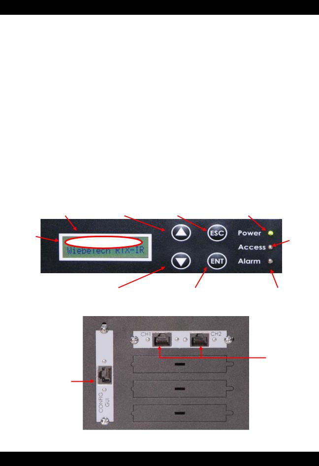
2.2 Identifying the Parts of RTX
|
LCD Panel on front of RTX |
|
|
LCD |
Up |
ESC (escape, exit) |
Power LED |
|
|
|
|
IP Address |
Access |
|
LED |
||
|
Down |
ENT (enter) |
|
Alarm LED |
|
Ports on rear of RTX |
iSCSI Ports
Ethernet Configuration Port
(for GUI configuration)
2.3 Warnings and Notices: Please read the following before beginning installation. |
|
General Care |
|
RT X 4 1 0/ 6 1 0 /8 0 1 - I R U s e r M an u a l A9 - 4 6 8 - 0 0 0 5 R E V 1 . 0 |
- 3 - |

CRU
The main circuit boards of the HDD carriers are susceptible to static electricity. Proper grounding is strongly recommended to prevent electrical damage to the enclosure or other connected devices, including the computer host. Avoid all dramatic movement, tapping on the unit, and vibration.
Avoid placing the HDD carriers close to magnetic devices, high voltage devices, or near a heat source. This includes any place where the product will be subject to direct sunlight. Do NOT allow water to make contact with the carrier or receiving frame.
Before starting any type of hardware installation, ensure that all power switches have been turned off and all power cords have been disconnected to prevent personal injury and damage to the hardware.
To avoid overheating, RTX should be operated in a well-ventilated area and in such a way that sufficient airflow is maintained across the controller chips.
RAID
Use only hard drives that are in perfect condition. Avoid using drives that have ever developed bad sectors during previous usage. This could lead to possible device failure or loss of data.
RTX supports SATA hard drives of various specifications and different capacities. However, we recommend using drives of the same brand and type for optimal performance. If drives of different capacities are used in a RAID, the capacity of the smallest drive will determine how much of each drive is used. The additional capacity on the larger drives will not be used by the RAID.
RAID level 0 will allow you to use the full combined capacity of the drives, and offers the best data transfer speeds. However, RAID 0 offers no protection for the data. If one drive fails in a RAID 0, the data on all of the drives is irretrievably lost. Before creating a RAID, investigate the various RAID types and choose the one that is best for your needs.
Always back up data before switching RAID types. Switching RAID types will destroy current data. You must reformat your drives afterwards.
2.4 Terminology
|
Terminology |
RAID |
Redundant Array of Independent Disks. There are different RAID levels with |
|
different degrees of data protection, data availability, and performance. |
JBOD |
“Just a Bunch Of Disks”. JBOD needs at least one hard drive. |
PD |
Physical Disk. Belongs to the member disk of one specific RAID group. |
RG |
RAID Group. A collection of removable media. One RG consists of a set of |
|
VDs and owns one RAID level attribute. |
VD |
Virtual Disk. Each RG could be divided into several VDs. The VDs from one |
|
RG have the same RAID level, but may have different volume capacity. |
LUN |
Logical Unit Number. A unique identifier for a SCSI device which enables |
|
computers to differentiate among separate SCSI devices. |
GUI |
Graphical User Interface. |
RAID cell |
The number of subgroups of PDs in an RG. |
DS |
Dedicated Spare disk. A spare disk dedicated to one specific RG and is used |
|
when another disk in the RG fails. |
GS |
Global Spare disk. A spare disk that is shared among all RGs and is used |
|
when another disk in an RG fails. |
WWN |
World Wide Name. A unique identifier that identifies a particular PD. |
CHAP |
Challenge Handshake Authentication Protocol. An optional security |
|
mechanism to control access to RTX through its iSCSI data ports. |
iSNS |
Internet Storage Name Service. This protocol allows automated discovery, |
|
management, and configuration of iSCSI devices on a TCP/IP network. |
3 Introduction to RAID
RT X 4 1 0/ 6 1 0 /8 0 1 - I R U s e r M an u a l A9 - 4 6 8 - 0 0 0 5 R E V 1 . 0 |
- 4 - |
|
|

CRU
A RAID (Redundant Array of Independent Disks) is an array of multiple hard drives that are combined in a way that provides faster performance and/or data safety. Your RTX unit is capable of creating and managing several different varieties of RAID. You may choose your preferred RAID level based on factors such as disk capacity, desired data safety, and desired performance.
3.1 Summary of RAID Levels
RTX supports RAID Levels 0, 1, 3, 5, 6, 0+1, 10, 30, 50, 60, & JBOD. RAID Level 5 is most commonly used by those seeking an optimal balance of speed and data safety.
RAID Features and Performance
RAID |
Description |
Min. |
Data |
Data Transfer Rate |
|
Level |
Drives |
Redundancy |
|||
|
|
||||
|
Also known as striping. Data distributed across |
|
No data |
|
|
0 |
multiple drives in the array. There is no data |
2 |
Very high |
||
protection |
|||||
|
protection. |
|
|
||
|
|
|
|
||
|
Also known as mirroring. All data replicated on two |
|
|
|
|
|
separate disks. This is a high availability solution, |
|
|
Reads are higher than a |
|
1 |
but due to the 100% duplication, only half the total |
2 |
1 drive |
single disk; Writes are |
|
|
disk capacity is available for data storage. |
|
|
similar to a single disk |
|
|
|
|
|
|
|
|
Also known as Bit-Interleaved Parity. Data and |
|
|
|
|
|
parity information is subdivided and distributed |
|
|
|
|
3 |
across all disks. Parity must be equal to the |
3 |
1 drive |
Reads are similar to RAID 0 |
|
smallest disk capacity in the array. Parity |
|||||
|
|
|
|
||
|
information normally stored on a dedicated parity |
|
|
|
|
|
disk. |
|
|
|
|
|
Also known as Block-Interleaved Distributed |
|
|
|
|
5 |
Parity. Data and parity information is subdivided |
3 |
1 drive |
Reads are similar to RAID 0 |
|
and distributed across all disks. Can withstand the |
|||||
|
failure of one drive. The total capacity of all but |
|
|
|
|
|
one of the drives is available for data storage. |
|
|
|
|
|
Two parity bits are used to create double |
|
|
|
|
6 |
redundancy. Can withstand the failure of two |
4 |
2 drives |
Slightly less than RAID 5 |
|
drives. The total capacity of all but two of the |
|||||
|
|
|
|
||
|
drives is available for data storage. |
|
|
|
|
|
Also known as a mirror of striped drives. Data and |
|
|
|
|
|
parity information is subdivided and distributed |
|
|
Transfer rates are similar to |
|
0+1 |
across all disks. Parity must be equal to the |
4 |
1 drives* |
||
smallest disk capacity in the array. Parity |
RAID 0 |
||||
|
|
|
|||
|
information normally stored on a dedicated parity |
|
|
|
|
|
disk. |
|
|
|
|
|
Also known a stripe of mirrors. Data is striped |
|
|
Transfer rates are similar to |
|
10 |
across two separate disks and mirrored to another |
4 |
1 drives* |
||
RAID 0 |
|||||
|
disk pair. |
|
|
||
|
|
|
|
||
|
Also known as Striping Dedicated Parity Array. |
|
|
|
|
30 |
RAID 30 breaks up data into smaller blocks, and |
6 |
2 drives** |
Transfer rates are similar to |
|
then stripes the blocks of data to each RAID 3 |
RAID 0 |
||||
|
|
|
|||
|
RAID set. |
|
|
|
|
50 |
RAID 50 combines the straight block-level striping |
6 |
2 drives** |
Transfer rates are similar to |
|
of RAID 0 with the distributed parity of RAID 5 |
RAID 0 |
||||
|
|
|
|||
|
RAID 60 combines the straight block-level striping |
|
|
Transfer rates are similar to |
|
60 |
of RAID 0 with the distributed double parity of |
8 |
4 drives*** |
||
RAID 0 |
|||||
|
RAID 6 |
|
|
||
|
|
|
|
||
JBOD |
Just A Bunch of Disks. This is not an actual RAID |
1 |
0 drives |
Very high |
|
level as each disk is treated as its own entity. |
|||||
|
|
|
|
*If both drives in either the RAID 0 or RAID 1 set fail, then the entire RAID will fail. If only one drive in each of the RAID 0 and RAID 1 sets fail, then the RAID is preserved.
**One drive from each of the striped RAID sets could fail without loss of data. If two drives in the same striped RAID set fail, then the entire RAID will fail.
RT X 4 1 0/ 6 1 0 /8 0 1 - I R U s e r M an u a l A9 - 4 6 8 - 0 0 0 5 R E V 1 . 0 |
- 5 - |
|
|

CRU
***Two disks from each of the RAID 6 sets could fail without loss of data. The loss of three disks in the same striped RAID 6 set fails, then the entire RAID will fail.
4 Introduction to iSCSI
4.1 What is iSCSI?
iSCSI is a technology that allows a data storage device to be accessed over a TCP/IP network using SCSI protocols. When your computer’s OS receives a request for data access, it generates a SCSI command and then sends an IP packet across a network or direct Ethernet connection. A software utility known as an iSCSI initiator is used to generate the SCSI commands. Such a utility must be installed on the computer before it can access an iSCSI storage device (See Section 8 for installation instructions).
4.2 What is the Benefit of iSCSI?
An iSCSI storage device can be placed anywhere throughout a network, so the device can reside at a great distance from the computer which accesses it. It is also a very fast connection when used on a gigabit network, achieving speeds of 100 megabytes (MB)/sec or more. The connection it uses (RJ45— standard Ethernet port) is commonly found on desktop and laptop computers, so there is no need to purchase potentially expensive host bus adapters to provide a connection.
4.3 What is iSCSI Not?
iSCSI storage devices are not Network Attached Storage (NAS) devices. They have no built-in server capabilities and therefore cannot be accessed by more than one computer at a time. Multiple computers can only access the data if the iSCSI device is first attached to a single computer which is then set up as a server.
5 Installation Steps
5.1 Hard Drive Installation
a)Pull the ejection handle on the TrayFree bay to open the bay door.
b)Insert a bare SATA hard drive into the bay. Make sure it is label-side up with the SATA connection on the drive inserted first.
c)Shut the bay door.
d)You can optionally secure each bay door. Doing so is not necessary to operate RTX.
•For RTX410 and RTX610, Insert an RTX Key into its key lock and turn it 90 degrees clockwise.
•For RTX801-IR, use the Lock Tool to slide the lock to the “locked” position.
Sticker Card
Use the stickers on the provided sticker card to label each drive. This will prevent the drives from getting mixed up when they are removed from the bays.
5.2 Operating RTX
a)Connect RTX to a computer or network using the included Ethernet cable. Plug one cable into the “CH- 1” port. You can optionally plug a second cable into the “CH-2” port. The purpose of having multiple iSCSI channels is to provide redundancy/failover and increased performance.
b)Connect RTX to a power outlet with the included power cord.
c)Install the hard drives into RTX (See Section 5.1).
d)Flip the power switch on the rear of the unit to turn on RTX.
e)If you have not yet configured RTX for access, refer to Sections 6, 7, and 8. Section 6 will tell you how to connect RTX to your network or computer. Section 7 contains instructions for accessing the GUI and
RT X 4 1 0/ 6 1 0 /8 0 1 - I R U s e r M an u a l A9 - 4 6 8 - 0 0 0 5 R E V 1 . 0 |
- 6 - |
|
|

CRU
creating a usable RAID set. Section 8 contains instructions on how to access RTX through an iSCSI initiator.
f) Format the drive. When a hard drive is first used with RTX, or when a RAID set has been created and the user connects to RTX through an iSCSI initiator, it will show up as a blank, unallocated drive. You’ll need to format the drive in RTX before you can use it See Section 9 for instructions on how to format the drive with Mac or Windows operating systems. Note that formatting a drive will erase all data on the drive, so be sure to back up your data before installing the hard drives into this enclosure and before beginning this operation.
5.3 Recovering from a Failed RAID
If one hard drive of a RAID set with data redundancy has failed or has been unplugged or removed, then the status of the RAID Group will report that the RAID is degraded and RTX will automatically search for a spare disk to rebuild the RAID. If none are found, RTX will search for a global spare disk. If neither is found, it will wait for the user to remove the failed hard drive and insert a working replacement.
6 Network Configuration
6.1 Connecting RTX to Your Network or Computer
a) Plug an Ethernet cable into the Config GUI port on the rear of RTX.
b) Connect the other end of the Ethernet cable to your network. This usually means plugging it into a router or hub. In an office environment, you may have a network jack built into your office wall. If a network connection is not available, you can connect the Ethernet cable directly to an RJ45 (Ethernet) port on your computer.
c) Connect the power cable to the rear of RTX and to a grounded electrical outlet. d) Turn on RTX’s power using the switch on the rear panel.
6.2 Using the LCD to Configure the Config GUI Port
RTX has both an LCD interface and a GUI. The LCD interface has only basic functionality and is mainly used to configure the IP address of the Config GUI port. Once the Config GUI has been configured, the GUI can be used to fully configure RTX.
6.2.1 Navigating the LCD menu
Use the four function keys, ▲ (Up), ▼ (Down), ESC (Escape) and ENT (Enter) to manipulate the LCD interface. After pressing ENT (Enter) key, you can use the ▲ (Up) and ▼ (Down) keys to select a function. If there is an alarm or error message, the LCD will display the related information.
6.2.2 LCD Functions
|
System Info |
Displays the details of RAM and firmware. |
|
|
|
Alarm Mute |
Turns off the alarm sound when an error occurs. |
|
|
|
Reset/Shutdown |
Resets or shuts down the controller. |
|
|
|
|
To use “Quick Install” to set up a volume by three steps. CRU-DataPort does not recommend |
|
|
|
Quick Install |
using the Quick Install option to set up your RTX. For quick set-up of a RAID, refer to Section |
|
|
|
|
7.7.1. |
|
|
|
Volume Wizard |
Smart steps to create a volume. Please refer to Section 7.7.1 for detailed operation steps in |
|
|
|
the web GUI. |
|
|
|
|
|
|
|
|
|
View IP Setting |
Display the current IP address, subnet mask, and gateway. |
|
|
|
Change IP Config |
Sets the IP address, subnet mask, and gateway. You can choose to use DHCP server (for IP |
|
|
|
address allocation) or manually specify the IP address. |
|
|
|
|
|
|
|
|
|
|
Restores factory defaults: |
|
|
|
Reset to Default |
Default Administrator Name: admin |
|
|
|
Default Administrator Password: 1234 |
|
|
|
|
|
Default User Name: user |
|
|
|
|
Default User Password: 1234 |
|
|
|
|
|
|
|
|
RT X 4 1 0/ 6 1 0 /8 0 1 - I R U s e r M an u a l A9 - 4 6 8 - 0 0 0 5 R E V 1 . 0 |
- 7 - |
|
|
|
|
|
|
|
CRU
Default IP address: 192.168.0.1
Default subnet mask: 255.255.255.0
Default gateway: 192.168.0.254
6.2.3 RTX LCD Menu Diagram
Use the following chart for reference when following the instructions in Section 6.2.4 for setting up RTX according to your network type.
Main Menu |
2nd Menu Screen |
|
3rd Menu Screen |
4th Menu Screen |
5th Menu Screen |
|
6th Menu |
|
|
|
|
|
|
|
|
|
Screen |
|
|
|
[Firmware Version |
|
|
|
|
|
|
[System Info.] |
|
x.x.x] |
|
|
|
|
|
|
|
[RAM Size |
|
|
|
|
||
|
|
|
|
|
|
|
||
|
|
|
xxx MB] |
|
|
|
|
|
|
[Alarm Mute] |
|
[ENT:OK |
|
|
|
|
|
|
|
ESC: Back] |
|
|
|
|
|
|
|
|
|
|
|
|
|
|
|
|
|
|
[Reboot] |
[ENT:OK |
|
|
|
|
|
[Reset/Shutdown] |
|
ESC: Back] |
|
|
|
||
|
|
|
|
|
|
|
||
|
|
[Shutdown] |
[ENT:OK |
|
|
|
||
|
|
|
|
|
|
|||
|
|
|
ESC: Back] |
|
|
|
||
|
|
|
|
|
|
|
|
|
|
|
|
RAID 0 |
|
|
|
|
|
|
|
|
RAID 1 |
|
|
|
|
|
|
|
|
RAID 3 |
|
[Apply The |
[ENT:OK |
|
|
|
[Quick Install] |
|
RAID 5 |
|
|
|
||
|
|
|
Config] |
ESC: Back] |
|
|
||
|
|
|
RAID 6 |
|
|
|
||
|
|
|
|
|
|
|
|
|
|
|
|
RAID 0+1) |
|
|
|
|
|
|
|
|
xxx GB |
|
|
|
|
|
|
|
|
[Local] |
|
|
|
|
|
|
|
|
RAID 0 |
|
|
|
[Apply The |
|
|
|
|
RAID 1 |
|
|
|
||
|
[Volume Wizard] |
|
[Use default |
[Volume Size] |
|
Config] |
||
|
|
RAID 3 |
|
|||||
|
|
algorithm] |
xxx GB |
|
[ENT:OK |
|||
|
|
|
RAID 5 |
|
||||
|
|
|
|
|
|
ESC: Back] |
||
CRU-DataPort |
|
|
RAID 6 |
|
|
|
||
|
|
|
|
|
|
|||
|
|
RAID 0+1 |
|
|
|
|
||
RTX |
|
|
|
|
|
|
||
|
|
[IP Config] |
|
|
|
|
|
|
|
|
|
|
|
|
|
|
|
|
|
|
[Static IP] |
|
|
|
|
|
|
|
|
[IP Address] |
|
|
|
|
|
|
[View IP Setting] |
|
[DHCP IP] |
|
|
|
|
|
|
|
[IP Subnet Mask] |
|
|
|
|
|
|
|
|
|
|
|
|
|
|
|
|
|
|
[255.255.255.0] |
|
|
|
|
|
|
|
|
[IP Gateway] |
|
|
|
|
|
|
|
|
[192.168.010.254] |
|
|
|
|
|
|
|
|
[DHCP] |
[ENT:OK |
|
|
|
|
|
|
|
ESC: Back] |
|
|
|
||
|
|
|
|
|
|
|
|
|
|
|
|
|
|
[IP Address] |
Adjust IP |
|
|
|
|
|
|
|
address |
|
|
|
|
|
|
|
|
|
|
|
|
|
|
|
|
|
[IP Subnet |
Adjust Submask |
|
|
|
[Change IP Config] |
|
[Static IP] |
Mask] |
IP |
|
|
|
|
|
|
[IP Gateway] |
Adjust Gateway |
|
|
||
|
|
|
|
|
IP |
|
|
|
|
|
|
|
|
|
|
|
|
|
|
|
|
|
[Apply IP |
[ENT:OK |
|
|
|
|
|
|
|
Setting] |
ESC: Back] |
|
|
|
|
|
|
|
|
|
|
|
|
[Reset to Default] |
|
[ENT:OK |
|
|
|
|
|
|
|
|
ESC: Back] |
|
|
|
|
|
|
|
|
|
|
|
|
|
|
RT X 4 1 0/ 6 1 0 /8 0 1 - I R U s e r M an u a l A9 - 4 6 8 - 0 0 0 5 R E V 1 . 0 |
- 8 - |
|
|

CRU
6.2.4 Instructions for Differing Network Connection Types
DHCP-Enabled Network
On DHCP networks, a new IP address is dynamically assigned to RTX’s Config GUI port as soon as the network detects it. You can determine this address by checking the LCD interface on the front of RTX. It will appear in this format: xxx.xxx.xxx.xxx. Simply type this IP address into a web browser on your computer. This will access RTX’s GUI, which you will use to configure the unit.
Static Network
a) Check your computer’s IP address, subnet mask, and gateway. Mac users can find this information in System Preferences Network.
To do this in Windows, open Network and Sharing Center in the Control Panel (Also called “View Network Status and Tasks” under the “Network and Internet” category). On the left pane, select “Change adapter settings”. Right-click on your network (likely called Local Area Connection) and select Properties. On the new window that opens, select “Internet Protocol Version 4 (TCP/IPv4)” and click the Properties button. Your computer’s IP address, subnet mask, and gateway will be displayed.
b)On the RTX LCD interface, press ENT and then scroll up or down to Change IP Setting. Press ENT.
c)Scroll up or down to find Static. Press ENT.
d)Change the IP address to closely match what your computer is using. Or, if you are on a business network, have your IT administrator assign you an IP address. The IP address you select must NOT be in use by another device.
For example, if your computer's IP address is 192.168.0.9, you might change the RTX’s IP to 192.168.0.7. On smaller networks, each of the first three octets must be the identical to your computer’s IP address! When changing the IP address you'll notice that a box flashes over the digit to be changed. While the digit is selected, press ▲ (Up) or ▼ (Down) to change it. Press ENT to move to the next digit.
e)After the IP address is set, enter the subnet mask address exactly as it is shown on your computer’s TCP/IP settings.
f)Next, enter the gateway address exactly as it is shown on your computer’s TCP/IP settings.
g)Confirm the settings change. To confirm, press ▲ (Up) for “yes” and then press ENT again.
h)Type the RTX’s new IP address into a web browser on your computer. This will access the RTX’s GUI, which you will use to configure the unit.
Direct Connection to a Computer
The instructions are similar to those for a static network (see above), except that your computer will not have an IP address assigned if it’s not a part of a network. Since RTX and your computer must have similar IP addresses, you will assign an IP address to your computer based upon the default IP address of RTX.
a) Check RTX’s LCD to find out the IP address of the Config GUI configuration port. It will appear
RT X 4 1 0/ 6 1 0 /8 0 1 - I R U s e r M an u a l A9 - 4 6 8 - 0 0 0 5 R E V 1 . 0 |
- 9 - |
|
|

CRU
in this format: xxx.xxx.xxx.xxx.
b) Next, change your computer’s IP address so that all but the last three digits match RTX ’s address. For example, if RTX’s IP address is 169.254.12.62, you might assign your computer the number 169.254.12.63 (assuming no other computer on the network is already using that number). The process of changing your computer’s IP address varies depending on its operating system.
Mac users can go to System Preferences Network.
For modern Windows operating systems, open Network and Sharing Center in the Control Panel (Also called “View Network Status and Tasks” under the “Network and Internet” category). On the left pane, select “Change adapter settings”. Right-click on your network (likely called Local Area Connection) and select Properties. On the new window that opens, select “Internet Protocol Version 4 (TCP/IPv4)” and click the Properties button. By default, your computer is probably set to receive a new IP address automatically. Change the setting to manual configuration and then type in the IP address.
c)Using the same process as the previous step, change the computer’s Subnet Mask setting to match RTX’s Subnet Mask setting.
d)Finally, use RTX’s LCD interface to change RTX ’s Gateway setting. It should match the IP address you assigned to your computer. When changing the gateway address you'll notice that a box flashes over the digit to be changed. While the digit is selected, press ▲ (Up) or ▼ (Down) to change it. Press ENT to move to the next digit. After the gateway address is set, press ENT all the way to the end and confirm the settings change. To confirm, press ▲ (Up) for “yes” and then press ENT again.
e)Launch a web browser and type RTX’s IP address into the URL bar, as if it were a website. This will access RTX’s GUI, which you will use to configure the unit.
The tables below show example settings. The first table shows the type of settings that will appear by default. The next table shows how the settings might look after you’ve made changes.
|
|
RTX |
Computer |
|
|
|
|
IP Address |
|
169.254.12.62 |
(blank) |
Mask |
|
255.255.000.000 |
(blank) |
Gateway |
|
000.000.000.000 |
(blank) |
|
Before making changes |
||
Connecting From Home to Office
|
RTX |
Computer |
IP Address |
169.254.12.62 |
169.254.12.63 |
Mask |
255.255.000.000 |
|
255.255.000.000 |
||
Gateway |
169.254.12.63 |
(blank) |
|
After making changes |
|
RTX can also be used over the Internet. If you are connecting to an RTX at your office from home, you will need to contact your IT administrator to set up a VPN client in order to log in to the office network. Once you have logged in to the office network, you can access RTX just as if you were actually at your office (see instructions for DHCP-enabled Network, Static Network, or Direct Connection to a Computer, depending on how your office network is configured).
7 Using the GUI
You will use the web browser-based GUI to set up a RAID and create logical volumes on RTX. After setting up access to the GUI and accessing it through a web browser (see Section 6.2 for instructions),
RT X 4 1 0/ 6 1 0 /8 0 1 - I R U s e r M an u a l A9 - 4 6 8 - 0 0 0 5 R E V 1 . 0 |
- 10 - |
|
|
CRU
the GUI’s main page should load, displaying a picture of RTX with several options to the left. When you click on any option, you will be prompted for a username and password. The default administrator username is "admin" and the default password is "1234."
7.1 GUI Indicators
The top right hand corner of the GUI window displays several indicators.
RAID light: Green indicates that the RAID is working properly. Red indicates a RAID error. If no RAID is set up, the light will remain green.
Temperature light: Green indicates normal. Red indicates abnormal system temperature and probable overheating.
Voltage light: Green indicates normal. Red indicates abnormal voltage status like a power surge or a bad power supply.
Fan light: Green indicates that the fan is working properly. Red indicates a malfunctioning fan that needs to be replaced. (only applies to RTX610-IR and 801-IR).
RT X 4 1 0/ 6 1 0 /8 0 1 - I R U s e r M an u a l A9 - 4 6 8 - 0 0 0 5 R E V 1 . 0 |
- 11 - |
|
|

CRU
7.2Overview of GUI Architecture
•Quick installation
•System configuration
oSystem settings
oIP address
oLogin settings
oMail settings
oNotification settings
•iSCSI configuration
oEntity property
o |
NIC |
o |
Node |
o |
Session |
oCHAP account
•Volume configuration
oVolume creation wizard
oPhysical disk
oRAID group
oVirtual disk
oLogical unit
•Enclosure management
oSES configuration
o Hardware monitor
oS.M.A.R.T.
•Maintenance
oSystem information
o Upgrade
oReset to factory default
oImport and export
oEvent log
oReboot and shutdown
•Online support
oProduct Information and Specs
oFAQ and Downloads
•Logout
7.3Manually Creating a Usable RAID Set
Use these sets of instructions to create a usable RAID set. To quickly create a RAID 0, 1, 3, 5, 6, or 0+1 set using the Volume Creation Wizard, see Section 7.6.1.
7.3.1 Manually Creating a RAID Group
To manually create a usable RAID set, you will first need to create a new RAID Group.
a) Click the “Create” button at the bottom of the page to open the RAID Group creation screen.
RT X 4 1 0/ 6 1 0 /8 0 1 - I R U s e r M an u a l A9 - 4 6 8 - 0 0 0 5 R E V 1 . 0 |
- 12 - |
|
|

CRU
b)Enter a name for the new RAID Group in the first field, and then select your desired RAID type or JBOD from the dropdown box. CRU-DataPort recommends RAID 5 for maximum performance, capacity, and security. For more information on RAID, see Section 3. Click “Select PD” to select the drives that will be added to the RAID Group.
Note: Drives must be marked as Free Disks before they can be added to a RAID Group. To set drives to Free Disks, see Section 7.7.2, subsection “Modifying Physical Disks”.
c)All available Free Disks will be displayed. Check the drives that you wish to add to the RAID Group, then click “Confirm”.
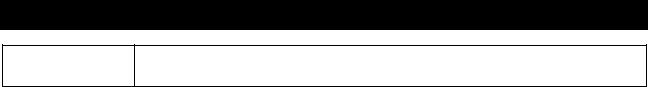
d)The selected Physical Disks will now be displayed in the RAID Group creation screen. Enable or Disable Write Cache, Standby, Readahead, and Command Queuing based on your needs. Most RAID Groups will be fine with the default settings. Then click “Next” to proceed to the confirmation screen.
RT X 4 1 0/ 6 1 0 /8 0 1 - I R U s e r M an u a l A9 - 4 6 8 - 0 0 0 5 R E V 1 . 0 |
- 13 - |
|
|
CRU
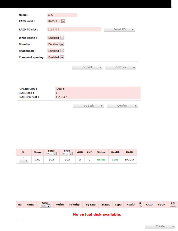
e)On the confirmation screen, verify that the RAID level is correct and all of the disks you selected are displayed under “RAID PD slot”, then click “Confirm” to create the RAID Group.
f)The RAID Group will now display on the main RAID Group screen. To finish manually creating a usable RAID set, a Virtual Disk still must be created and a Logical Unit must be attached. Go to the next section, “Manually Creating a Virtual Disk”.
If you opted to create JBOD drives, skip to Section 8.3.3, “Manually Attaching a Logical Unit” as Virtual Disks have already been created for each JBOD drive.
7.3.2Manually Creating a Virtual Disk
After a RAID Group has been created, you can create associated Virtual Disks. You must create at least one Virtual Disk to access the drives of RTX with a computer.
a) Click the “Create” button at the bottom of the page to open the Virtual Disk creation screen.
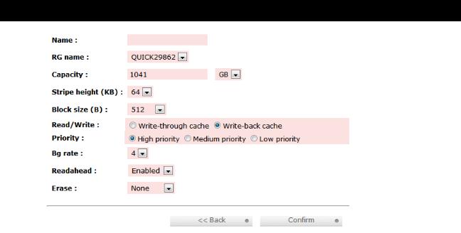
b)You will see the screen below. Fill in the information and then click “Confirm”. Each field is explained below the picture.
RT X 4 1 0/ 6 1 0 /8 0 1 - I R U s e r M an u a l A9 - 4 6 8 - 0 0 0 5 R E V 1 . 0 |
- 14 - |
|
|
CRU
Name
Enter a name for the Virtual Disk.
RG Name
Choose the RAID Group to which the Virtual Disk will be added.
Capacity
Enter the capacity of the Virtual Disk. The default uses the maximum capacity of the associated RAID Group. If you wish to create multiple Virtual Disks on the selected RAID Group, you will need to reduce the capacity below the maximum so that there is space left on the RAID Group for additional Virtual Disks.
Stripe height (KB)
Determines how RTX organizes the RAID. Normally the default option is preferred.
Block size
Determines the minimum file size for files that will be stored on the Virtual Disk. Higher block sizes can result in more wasted space if many small files are saved to the drive, but are necessary to take advantage of high capacity RAIDs. If you are creating a Virtual Disk over
2TB in size for use with MacOS 10.4.x or older, or for use with Windows XP, you must increase the block size to 4096KB to take advantage of the full capacity of the Virtual Disk.
Read/Write
Allows selection of cache type. Normally the default option is preferred.
Priority
Determines the priority that RTX will give to RAID activities (rebuild and initialization) versus priority given to file transfers. “High priority” will result in slower file transfers during initialization, but provide for faster initialization.
BG Rate
Background Task Priority. The higher the number, the more priority will be given to background input/output.
RT X 4 1 0/ 6 1 0 /8 0 1 - I R U s e r M an u a l A9 - 4 6 8 - 0 0 0 5 R E V 1 . 0 |
- 15 - |
|
|
 Loading...