

CRU Rhino Jr RJ400 Quick Start Manual
©2016 CRU Acquisition Group LLC, ALL RIGHTS RESERVED. CRU® and Rhino® are trademarks of CRU Acquisition Group, LLC and are
protected by trademark law.
Product Warranty
CRU warrants this product to be free of significant defects in material and workmanship for a period of three years from the original date
of purchase. CRU’s warranty is nontransferable and is limited to the original purchaser.
Limitation of Liability
The warranties set forth in this agreement replace all other warranties. CRU expressly disclaims all other warranties, including but not limited to, the implied warranties of merchantability and fitness for a particular purpose and non-infringement of third-party rights with respect
to the documentation and hardware. No CRU dealer, agent, or employee is authorized to make any modification, extension, or addition to
this warranty. In no event will CRU or its suppliers be liable for any costs of procurement of substitute products or services, lost profits,
loss of information or data, computer malfunction, or any other special, indirect, consequential, or incidental damages arising in any way
out of the sale of, use of, or inability to use any CRU product or service, even if CRU has been advised of the possibility of such damages.
In no case shall CRU’s liability exceed the actual money paid for the products at issue. CRU reserves the right to make modifications and
additions to this product without notice or taking on additional liability.
FCC Compliance Statement: “This device complies with Part 15 of the FCC rules. Operation is subject to the following two conditions:
(1) This device may not cause harmful interference, and (2) this device must accept any interference received, including interference that
may cause undesired operation.”
This equipment has been tested and found to comply with the limits for a Class B digital device, pursuant to Part 15 of the FCC Rules.
These limits are designed to provide reasonable protection against harmful interference when the equipment is operated in a home or
commercial environment. This equipment generates, uses, and can radiate radio frequency energy and, if not installed and used in accordance with the instruction manual, may cause harmful interference to radio communications.
In the event that you experience Radio Frequency Interference, you should take the following steps to resolve the problem:
1) Ensure that the case of your attached drive is grounded.
2) Use a data cable with RFI reducing ferrites on each end.
3) Use a power supply with an RFI reducing ferrite approximately 5 inches from the DC plug.
4) Reorient or relocate the receiving antenna.
Product Models Rhino Jr RJ400
Interface Types & Speeds SAS/SATA: up to 6 Gbps
Supported Drive Types 3.5-inch SATA hard drives
Data Connectors Four (4) SATA connectors
Supported Operating Systems Windows 10, 8, 7, and Vista
Windows Server 2012 and 2008 product families
OS X/macOS 10.9 “Mavericks” or newer
Linux distributions that support the connection type used
Torque 3.5-inch hard drives, #6-32 screws: 6 inch-pounds max.
Compliance EMI Standard: FCC Part 15 Class B, CE
EMC Standard: EN55022, EN55024
Product Weight 2.98 pounds (1.35 kg)
Product Dimensions 7.95” x 5.79” x 4.96” (202mm x 147mm x 126mm)
Technical Support Your investment in CRU products is backed up by our free technical support
for the lifetime of the product. Contact us through our website, cru-inc.com/
support or call us at 1-800-260-9800 or +1-360-816-1800.
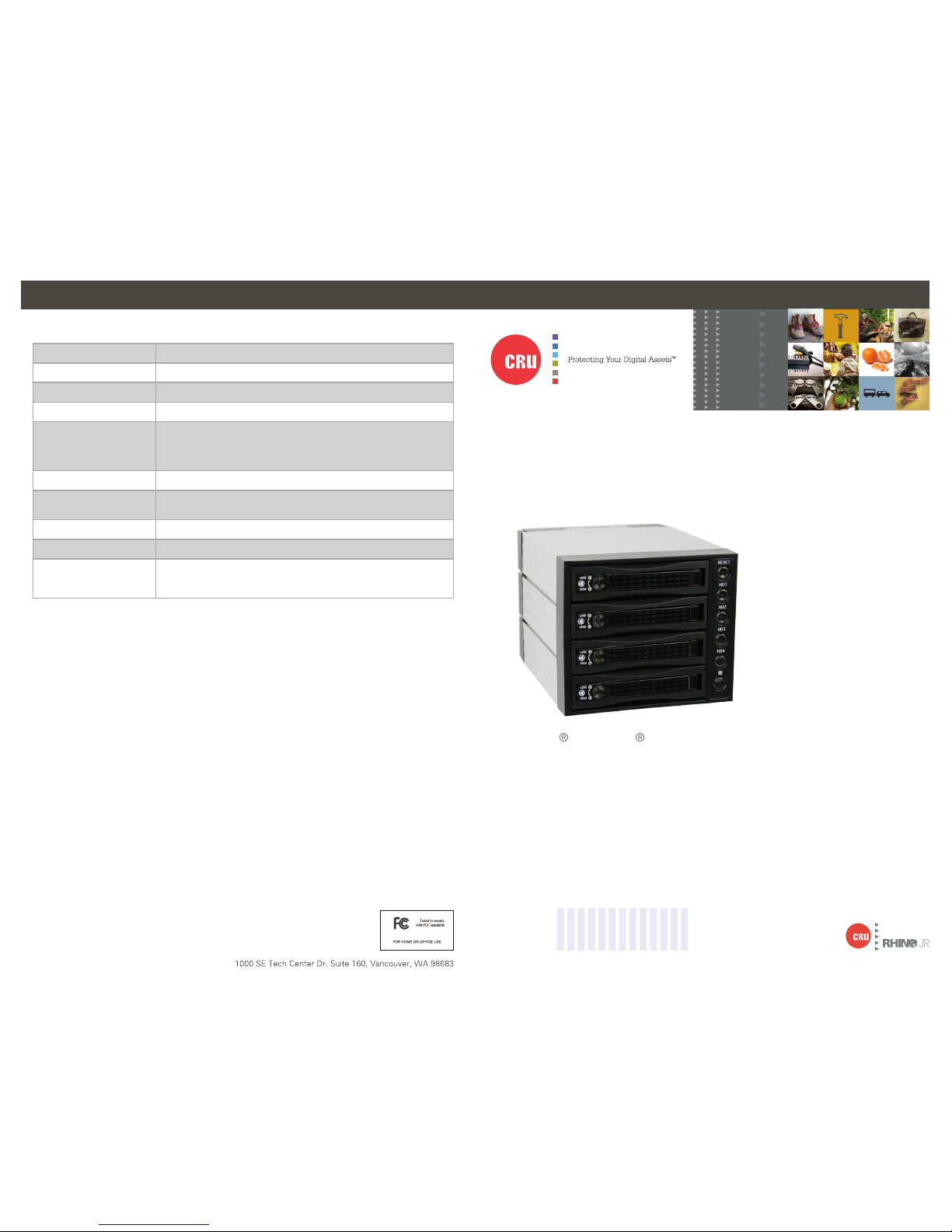
CRU® Rhino® Jr RJ400 Enclosure
Quick Start Guide
Features
• Houses up to four SATA drives for easy replacement and data archiving
• Integrated cooling fan
• Aluminum enclosure helps dissipate heat and ensures drive safety.
Part Number: A9-110-0005-1 Rev. 1.0
2 Rhino Jr RJ400 Quick Start Guide 3Rhino Jr RJ400 Quick Start Guide
CRU Mark
1 HARDWARE SETUP
1.1 FRAME INSTALLATION
a. Slide the Rhino Jr RJ400 removable drive enclosure into three open 5.25” drive bays in
your computer workstation.
b. Secure the RJ400 to the chassis with the mounting screws provided.
c. Attach four SATA data cables to the SATA connectors on the rear of the RJ400 (HD1, HD2,
HD3, and HD4) and attach the other end to the appropriate SATA ports on the computer’s
motherboard or SAS/SATA host card.
d. Attach two SATA power connectors from your workstation’s power supply to the two SATA
power connections on the rear of the RJ400 (POWER1 and POWER2). If your workstation
lacks SATA power connectors, you can use two Molex 4-pin power connectors instead.
1.2 DRIVE INSTALLATION
a. Eject the carrier from the frame by pressing in on the triangle symbol on the carrier.
b. Carefully insert a hard drive into the carrier and turn the drive/carrier assembly over.
c. Bottom-mount the drive into the carrier with the mounting screws provided.
d. With the carrier handle still ejected from the carrier, slide the drive ports-first into the drive
bay and apply firm pressure until the drive is seated.
e. Push the carrier handle in so it’s flush with the carrier.
f. You can optionally rot ate the lock switch on the carrier 90 degrees clockwise to secure the
carrier into the RJ400.
g. Press the carrier’s power button to the right of the carrier to power on the drive.
2 EJECTING DRIVES FROM THE RJ400
After ejecting a drive, you may need to restart your computer in order to remount the
drive unless you have a hotswap-capable host.
2.1 WINDOWS
a. Ensure that no file transfers are taking place by making sure that the Drive Power Switch
LED for that drive is not blinking, as disconnecting the unit while a file transfer is in prog-
ress can result in data loss.
b. Then press the power switch to turn off the drive in the carrier.
c. If the lock is engaged, rotate the lock switch 90 degrees counterclockwise.
d. Eject the carrier from the frame by pressing in on the triangle symbol on the carrier.
If you have a SAS/SATA host card or motherboard that supports hot-swapping,
then you should first unmount the volume by left-clicking on the the USB plug icon
with the green checkmark on the Desktop task bar and then selecting the proper
device from the menu that pops up. Volumes not on a hotswap-capable host may
not appear here.
2.2 OS X/macOS
a. First, ensure that no file transfers are taking place by making sure that the Drive Power
Switch LED for that drive is not blinking, as disconnecting the unit while a file transfer is in
progress can result in data loss.
b. Unmount the volume before powering down the drive by dragging the volume’s icon to the
Trash, or by selecting the volume and pressing Command + E.
c. Press the power switch to turn off the drive in the carrier.
d. If the lock is engaged, rotate the lock switch 90 degrees counterclockwise.
e. Eject the carrier from the frame by pressing in on the triangle symbol on the carrier.
3 LED BEHAVIOR
LED NAME COLOR STAT E DESCRIPTION
Drive Power
Switch
Green Solid The drive is powered on.
Amber Blinking or Solid The drive is being accessed by the computer host.
Fan
Green Solid The fan is operating properly.
Red Solid
The fan has failed. Please contact CRU Technical Support.
OverTemp/Reset Red Blinking
The internal unit temperature has reached the preset
threshold (see Section 4 for info on how to set the
threshold). The default threshold is 140° F/60° C. Press
the Reset button to silence the alarm.
4 TEMPERATURE ALARM THRESHOLD
The default temperature alarm threshold can be changed by moving jumper JP1 on the rear of the
RJ400 enclosure. The default threshold is 140° F/60° C. You can move the jumper to 131° F/55° C
or to 149° F/65° C.
 Loading...