

Crown WP2300S series Maintenance Manual

Maintenance Manual
WP2300S Series
●
Printed in Germany
Order Number: 812529-006
Revision Level B

This master manual is subject to continual updates.
It is meant exclusively for businesses authorized by CROWN.
It is not permitted to pass on the contents or copies thereof to third par ties.
CROWN Gabelstapler GmbH & Co. KG
- European Headquarter -
Moosacher Str. 52
80809 Munich
Germany
Phone +49 (0)89 93 00 2 - 0
Fax +49 (0)89 93 00 2 - 133
All rights reserved under international and Pan-American Copyright Agreement.
CROWN Equipment Corporation
Copyright 2002

Overview of Revisions:
Page A Rev.1 04/00 General corrections and additions to the text.
Reference to authorised service personnel added.
Page 63 Rev.2 05/05 General corrections and additions to text.
Additions to Safety Reverse Switch (SAS)
Used from serial no. 5A336576, except for 5A337937.
Additions to Brake Switch (BRS)
Used from serial no. 5A336576, except for 5A337937.
Page 64 Rev.2 05/05 Additions to Platform Control Switches (GCSR, GCSL, PLS)
Used from serial no. 5A336576, except for 5A337937.
Page 64_A Rev.2 05/05 Additions to Platform Logic (PLM)
Used from serial no. 5A336576, except for 5A337937.
Page 65_A Rev.2 05/05 Updated diagram, addition to PLM.
Page 66_A Rev.2 05/05 WP2340S diagram included.
Page 80_A Rev.2 05/05 Parameter setting for trucks with folded platform.
Parameter setting for trucks with fixed platform.
REVISION
Page 88_A Rev.2 05/05 Troubleshooting addition.
from page 102
up to page 112 Switch unit, fast/slow toggle switch, hydraulic PCB, main PCB removal/
from page 131 Rev.2 05/05 Corrections to diagrams and WP2340S addition.
from page 136 Rev.2 05/05 Wiring diagram updates. WP2340S addition.
Rev.2 05/05 General text corrections. Updates and additions: Control handle grip,
installation, potentiometer, safety reverse switch, horn switch, hand grip.
WP2300S 05/2005 • Printed in Germany
MS-REV-1723
A

Blank Page
Printed in Germany
B

Printed in Germany
TABLE OF CONTENT
I

Blank Page
Printed in Germany
M1.0-0000-000IIM1.0-0000-000IIII

TABLE OF CONTENT
Table of Content
REV– OVERVIEW OF REVISIONS PAGE SER-NR. CUT REV.
Overview of Revisions:....................................................... A .......................................................... Rev.2 05/2005
ITD – INTRODUCTION PAGE SER-NR. CUT REV.
Safety Symbols used in the Manual .................................. 3 ............................................................... Rev.1 04/00
General Maintenance and Repair Safety Notes ................ 3
Maintenance and Repair .................................................. 3 ............................................................... Rev.1 04/00
Before Leaving the Truck.................................................. 4
Before Carrying out Work on the Truck ............................ 4
Before Operating the Truck............................................... 4
Warnings and Labels on the Truck..................................... 4
General................................................................................. 7
Operating Instructions ...................................................... 7
Service Training................................................................ 7
Ordering Spare Parts ....................................................... 7
Using the Manual ............................................................. 7
Model-Number ..................................................................... 8
M1 – LUBRICATION AND ADJUSTMENT PAGE SER-NR. CUT REV.
Jacking up the Truck ........................................................... 11
Raising the Truck with a Crane ........................................... 11
Fixed Platform .................................................................. 11
Folding Platform ............................................................... 12
Both Platforms.................................................................. 13
Raising with a Forklift Truck............................................... 14
Component Access and Components .............................. 15
Maintenance ........................................................................ 18
Recommended Lubricants and Oils ................................. 18
Lubricants ................................................................... 18
Cold Store Trucks........................................................ 18
Truck Decommissioning ................................................... 18
Restoring the Truck to Service........................................... 18
Check and Maintenance Schedule .................................. 20
Safety Reverse Switch –
Functional Test ................................................................... 22
Grease items and grease intervals .................................. 30
Adjusting the Contact Pressure of the Castors
and the Drive Wheel ............................................................ 32
Torques ................................................................................ 33
M2 – HYDRAULICS PAGE SER-NR. CUT REV.
Hydraulic Symbols .............................................................. 37
Hydraulic System ................................................................ 41
Operation ......................................................................... 41
Removing the Hydraulic Unit............................................ 42
Replacing the Hydraulic Pump......................................... 43
Removal...................................................................... 43
Installation................................................................... 43
Commissioning and Bleeding the System........................ 43
Filters ............................................................................... 45
Replacing the Pressure Filter...................................... 45
Replacing the Suction and Return Filters.................... 45
Oil Change ....................................................................... 45
Replacing the Safety Valve............................................... 46
Safety Valve Setting ......................................................... 46
Safety Valve T est and Setting...................................... 46
WP2300S 05/2005 • Printed in Germany
III

TABLE OF CONTENT
Testing and Setting the Load-
Dependent Pressure Switch............................................. 47
M3 – DRIVE UNIT PAGE SER-NR. CUT REV.
Gear Unit .............................................................................. 51
Preparatory Measures ..................................................... 51
Removal........................................................................... 51
Maintenance .................................................................... 51
General ....................................................................... 51
Gear Unit Disassembly / Assembly.................................. 53
Disassembly................................................................ 53
Assembly .................................................................... 53
Preparing the Gear Unit .............................................. 53
Flange Shaft Assembly ............................................... 53
Pinion Shaft Assembly ................................................ 54
Adjusting the Bevel Gear Assembly ............................ 54
Final Assembly............................................................ 54
Assembly .................................................................... 55
M4 – ELECTRICS PAGE SER-NR. CUT REV.
Electrics - General............................................................... 59
Wire Colour Codes........................................................... 59
Abbreviations ................................................................... 60
Electrical Symbols............................................................ 62
Electrical Components ....................................................... 63
Travel Switch (POT, FS, RS)............................................. 63
Fast/Slow Switch (HSS) ................................................... 63
Safety Reverse Switch (SAS)........................................... 63
Safety Reverse Switch (SAS)........................................... 63 .................. Used from serial no. 5A336576,
................................................................................................................. except for 5A337937...........................
........................................................................................................................................................ Rev.2 05/2005
Brake Switch (BRS).......................................................... 63
Brake Switch (BRS) .......................................................... 63 .................. Used from ser ial no. 5A336576,
................................................................................................................. except for 5A337937...........................
........................................................................................................................................................ Rev.2 05/2005
Raise/Lower Switch (RAS, LOS)...................................... 64
Pressure Switch (PS) ....................................................... 64
Platform Control Switches (GCSR, GCSL, PLS).............. 64
Platform Control Switches (GCSR, GCSL, PLS).............. 64 .................. Used from ser ial no. 5A336576,
................................................................................................................. except for 5A337937...........................
........................................................................................................................................................ Rev.2 05/2005
Lift Limit Switch (LMS) ..................................................... 64
Horn Switch (HNS)........................................................... 64
Foot Switch (FTS) ............................................................ 64
Key Switch (KYS)............................................................. 64
Emergency Disconnect (BD)............................................ 64
Fuses (FU) ....................................................................... 64
OPTION
Thermal Switch (THS) ........................................... 64
Filter (WP2340S only) ...................................................... 64 ......................................................... Rev.2 05/2005
Diode D4 .......................................................................... 64 ......................................................... Rev.2 05/2005
Diode block (DB).............................................................. 64 ......................................................... Rev.2 05/2005
Platform Logic (PLM) ....................................................... 64_A.............. Used from serial no. 5A336576,
................................................................................................................. except for 5A337937...........................
........................................................................................................................................................ Rev.2 05/2005
WP2330S ......................................................................... 65
WP2330S ......................................................................... 65_A..................................................... Rev.2 05/2005
WP2335S ......................................................................... 66_A..................................................... Rev.2 05/2005
WP2340S ......................................................................... 66_A..................................................... Rev.2 05/2005
Battery.................................................................................. 67
IV
WP2300S 05/2005 • Printed in Germany

TABLE OF CONTENT
General ............................................................................ 67
Replacing the battery ....................................................... 67
Battery Discharge Indicator (BDI)...................................... 67
General ............................................................................ 67
Battery Discharge Indicator Setting (BDI) ........................ 68
Calibration................................................................... 68
SEM1 T raction Controller .................................................... 69
General................................................................................. 69
Precautionary Measures ............................................. 69
Operational Features ....................................................... 69
Speed Control ............................................................. 69
Reduced Speed Ranges............................................. 69
Downhill Speed Control............................................... 69
Regenerative Braking.................................................. 69
Anti - Roll Down Function............................................ 69
Hourmeter ................................................................... 70
Self Test ...................................................................... 70
Monitored Circuits ....................................................... 70
Protective Devices............................................................ 70
Polarity Protection....................................................... 70
Wiring Errors ............................................................... 70
Temperature ................................................................ 70
Start Sequence ........................................................... 71
Safety Class................................................................ 71
Maintenance .................................................................... 71
Replacing the SEM1 Traction Controller ........................... 72
Parameter Setting after Replacing the Traction Controller 72
Preparatory Measures ................................................ 72
Setting......................................................................... 72
Status LED.................................................................. 74
Programmer......................................................................... 75
General ............................................................................ 75
Operating SEM1 Controller Menu .................................... 76
General ....................................................................... 76
Menu Functions .......................................................... 76
PARAMETER CHANGE .............................................. 76
Menu Structure for Folded Platform ............................ 77
Menu Structure for Fixed Platform .............................. 78
Parameter Setting, Folded Platform................................... 79
Parameter Setting, Folded Platform................................... 80
Parameter Setting, Folded or Fixed Platform.................... 80_A .................................................... Rev.2 05/2005
Parameter Setting, Fixed Platform ..................................... 80
TESTER Menu ................................................................. 82
ALARMS Menu ................................................................ 83
Calibrating the Traction Pod Potentiometer,
PROGRAM VACC menu .................................................. 86
Preparatory Measures ................................................ 86
Calibration................................................................... 86
CONFIG Menu...................................................................... 87
SET MODEL .................................................................... 87
SET OPTIONS ................................................................. 87
Adjustments ..................................................................... 87
Traction Controller Safety Test.......................................... 88
Troubleshooting Platform Logic, Controller PN 815144.... 88_A..................................................... Rev.2 05/2005
Electric Motors .................................................................... 89
General Maintenance Instructions ................................... 89
Preparation ................................................................. 89
Important Maintenance Instructions ............................ 89
Traction Motor Maintenance ............................................... 90
Access to Brushes ........................................................... 90
WP2300S 05/2005 • Printed in Germany
V

TABLE OF CONTENT
Maintenance .................................................................... 90
Armature ..................................................................... 90
Bearings...................................................................... 90
Pump Motor Maintenance................................................... 91
Access to brushes............................................................ 91
Maintenance .................................................................... 91
Armature ..................................................................... 91
M5 – BRAKE PAGE SER-NR. CUT REV.
Brake .................................................................................... 95
Removal........................................................................... 95
Disassembly................................................................ 96
Test and Inspection ..................................................... 96
Assembly .................................................................... 96
Assembly.......................................................................... 97
Air Gap Setting................................................................. 97
Brake Moment Setting...................................................... 98
Testing the Brakes....................................................... 98
M6 – STEERING PAGE SER-NR. CUT REV.
Multitask Handle - Springs for
Return Function .................................................................. 101
Adjustment ....................................................................... 101
Removal........................................................................... 101
Assembly.......................................................................... 101
Tiller Handle......................................................................... 103
Main Components ............................................................ 103
Tiller Handle Component
Removal / Installation ......................................................... 104
Tiller Handle Shells .......................................................... 104
Removing the Upper and Lower Shells....................... 104
Fitting the Upper and Lower Shells ............................. 105
Switch Unit ....................................................................... 106
Removal...................................................................... 106
Switch Unit Installation ................................................ 106
"Fast/Slow" Toggle Switch ................................................ 107
Removal...................................................................... 107
Installation................................................................... 107
Hydraulic Board ................................................................ 107
Removal...................................................................... 107
Installation................................................................... 107
Main PC Board Removal/Installation................................ 107_B................................................... Rev.2 05/2005
Potentiometer................................................................... 108
Removal...................................................................... 108
Installation................................................................... 108
Safety Reverse Switch ..................................................... 109
Removal...................................................................... 109
Installation................................................................... 109
Horn Switch...................................................................... 110
Removal...................................................................... 110
Installation................................................................... 110
Handle.............................................................................. 111
Removal...................................................................... 111
Installation................................................................... 111
M7 – LIFTING MECHANISM PAGE SER-NR. CUT REV.
Lift Linkage .......................................................................... 115
Fork Height Setting .......................................................... 115
Lift Limit Cutout................................................................... 117
Lift Limit Cutout Setting .................................................... 117
WP2300S 05/2005 • Printed in Germany
VI

TABLE OF CONTENT
M8 – CYLINDERS PAGE SER-NR. CUT REV.
Lift Cylinders ....................................................................... 1 21
Operation ......................................................................... 121
Removal........................................................................... 121
Inspection......................................................................... 123
Replacing the Piston Seal ................................................ 123
M9 – PLATFORM PAGE SER-NR. CUT REV.
Folding Platform.................................................................. 127
Mechanical Setting........................................................... 127
Platform Switch Setting (PLS) .......................................... 128
Platform Suspension ........................................................ 129
Plate Spring Layers..................................................... 129
Side Gates, Mechanical Setting ....................................... 130
Fixed Platform WP2335S..................................................... 131
Replacing the Savety Switch............................................ 131
Fixed Platform WP2340S..................................................... 131_A .................................................. Rev.2 05/2005
Replacing the Savety Switch............................................ 131_A................................................... Rev.2 05/2005
Fixed Platform WP2340S..................................................... 132_A .................................................. Rev.2 05/2005
Replacing Switches below the Entry Bars (FPS 1 & FPS 2)132_A................................................... Rev.2 05/2005
DIA – ELECTRICAL DIAGRAMS PAGE SER-NR. CUT REV.
Notes to overall wiring diagram, standard version, folded
platform, WP2330S .............................................................. 136 ....................................................... Rev.2 05/2005
Overall Wiring Diagram, Standard, Folded Platf orm,
WP2330S .............................................................................. 137 ....................................................... Rev.2 05/2005
SCHEMATIC DIAGRAM................................................... 13 8 ....................................................... Rev.2 05/2005
TRACTION CONTROLLER - SEM1 LOGIC CIRCUIT..... 138 ....................................................... Rev.2 05/2005
TRACTION CONTROLLER - SEM1 POWER CIRCUIT ... 139 ....................................................... Rev.2 05/2005
PLATFORM CIRCUIT ...................................................... 139 ....................................................... Rev.2 05/2005
POWER UNIT CIRCUIT................................................... 140 ....................................................... Rev.2 05/2005
CONTROL HANDLE CIRCUIT......................................... 140 ....................................................... Rev.2 05/2005
PLATFORM LOGIC .......................................................... 141 .................................................... ... Rev.2 05/2005
Notes to overall wiring diagram, with Options, folded
platform, WP2330S .............................................................. 142 ....................................................... Rev.2 05/2005
Overall Wiring Diagram, with Options, Folded Platform,
WP2330S .............................................................................. 143 ....................................................... Rev.2 05/2005
SCHEMATIC DIAGRAM................................................... 14 4 ....................................................... Rev.2 05/2005
TRACTION CONTROLLER - SEM1 LOGIC CIRCUIT..... 144 ....................................................... Rev.2 05/2005
TRACTION CONTROLLER - SEM1 POWER CIRCUIT ... 145 ....................................................... Rev.2 05/2005
PLATFORM CIRCUIT ...................................................... 145 ....................................................... Rev.2 05/2005
POWER UNIT CIRCUIT................................................... 146 ....................................................... Rev.2 05/2005
CONTROL HANDLE CIRCUIT......................................... 146 ....................................................... Rev.2 05/2005
PLATFORM LOGIC .......................................................... 147 .................................................... ... Rev.2 05/2005
Notes to overall wiring diagram, standard version,
fixed platform, WP2335S ..................................................... 148 ....................................................... Rev.2 05/2005
Overall Wiring Diagram, Standard Version,
Fixed Platform, WP2335S.................................................... 149 ....................................................... Rev.2 05/2005
Notes to overall wiring diagram, with Options,
fixed platform, WP2335S ..................................................... 150 ....................................................... Rev.2 05/2005
Overall Wiring Diagram, with Options, Fixed Platform,
WP2335S .............................................................................. 151 ....................................................... Rev.2 05/2005
Diagrams, Standard Version, Fixed Platform, WP2340S... 152 ....................................................... Rev.2 05/2005
SCHEMATIC DIAGRAM................................................... 15 2 ....................................................... Rev.2 05/2005
TRACTION CONTROLLER - SEM1 LOGIC CIRCUIT..... 152 ....................................................... Rev.2 05/2005
POWER CIRCUIT - TRACTION & PUMP MOTOR ......... 153 ....................................................... Rev.2 05/2005
PLATFORM CIRCUIT ...................................................... 153 ....................................................... Rev.2 05/2005
POWER UNIT CIRCUIT................................................... 154 ....................................................... Rev.2 05/2005
CONTROL HANDLE CIRCUIT......................................... 154 ....................................................... Rev.2 05/2005
Diagrams, with Options, Fixed Platform, WP2340S .......... 155 ....................................................... Rev.2 05/2005
WP2300S 05/2005 • Printed in Germany
VII

TABLE OF CONTENT
SCHEMATIC DIAGRAM................................................... 155 ....................................................... Rev.2 05/2005
TRACTION CONTROLLER - SEM1 LOGIC CIRCUIT..... 15 5 ....................................................... Rev.2 05/2005
POWER CIRCUIT - TRACTION & PUMP MOTOR ......... 156 ....................................................... Rev.2 05/2005
PLATFORM CIRCUIT ...................................................... 156 ....................................................... Rev.2 05/2005
POWER UNIT CIRCUIT................................................... 157 ....................................................... Rev.2 05/2005
CONTROL HANDLE CIRCUIT......................................... 157 ....................................................... Rev.2 05/2005
Wire harness overview , folded platform,
WP2330S all versions ......................................................... 158 ....................................................... Rev.2 05/2005
Main Harness, Folded Platform, WP2330S, All Versions .. 159 ....................................................... Rev.2 05/2005
Control Handle - Wire Harness Folded Platform,
WP2330S, All Versions........................................................ 160 ....................................................... Rev.2 05/2005
Horn Switch - Wire Harness, Folded Platform,
WP2330S, All Versions........................................................ 161 ....................................................... Rev.2 05/2005
Wire harness overview, Fixed Platf orm,
WP2340S, All Versions....................................................... 162 ....................................................... Rev.2 05/2005
Wire harness overview, Fixed Platf orm,
WP2340S, All Versions....................................................... 163 ....................................................... Rev.2 05/2005
Control Handle - Wire Harness FFixed Platform,
WP2340S, All Versions........................................................ 164 ....................................................... Rev.2 05/2005
Horn Switch - Wire Harness Fixed Platform,
WP2340S, All Versions........................................................ 165 ....................................................... Rev.2 05/2005
Cables, Platform, Fixed Platform, WP2340S,
All Ver sions .......................................................................... 166 ....................................................... Rev.2 05/2005
Power Cables ....................................................................... 167
HYD – HYDRAULIC SCHEMATIC PAGE SER-NR. CUT REV.
Hydraulic Schematic ........................................................... 171
VIII
WP2300S 05/2005 • Printed in Germany

Printed in Germany
SAFETY
1

Blank Page
Printed in Germany
M1.0-0000-0002M1.0-0000-00022
SAFETY
Safety Symbols used in the Manual
To help guide you through the manual and to highlight
particular danger areas, we have used graphic illustrations:
DANGER
This symbol indicates life-threatening risks
●
Failure to comply with this notice ma y
result in severe or fatal injuries to yourself
or other people.
WARNING
This symbol indicates the risk of serious
injury and/or serious material damage.
●
Failure to comply with this notice ma y
result in severe injuries to yourself or other
people and/or serious material damage.
CAUTION
This symbol indicates the risk of minor
injury and/or minor material damage.
●
Failure to comply with this notice ma y
result in minor injuries to yourself or other
people and/or minor material damage.
General Maintenance and Repair Safety Notes
DANGER
Read the safety notices in the truck Maintenance and Operator's Manuals.
●
Failure to do so could result in severe or
fatal injuries to maintenance personnel
and/or other persons.
Motorised vehicles can be dangerous if maintenance
and service are neglected. For this reason maintenance
and inspections must be carried out at regular short
intervals by trained personnel working to approved
company guidelines.
DANGER
Follow all national/local safety regulations
applicable for maintenance work, e.g. for
work on higher levels.
●
Failure to do so could result in severe or
fatal injuries to maintenance personnel
and/or other persons.
Maintenance and Repair
1. Maintenance work must only be carried out in
accordance with the test and maintenance program contained in the present Maintenance
Manual and any applicable service notices.
INFORMATION
Contains additional information with
supplementary notes and hints.
OPTION
These items relate to optional features not
OPTION
supplied with the standard version.
2. Only qualified and authorised personnel may
carry out work on the truck.
3. Always keep fire extinguishers in good working
condition. Do not approach fluid levels or leaks
with a naked flame.
4. To clean, use a non flammable, non combustible
cleaning solution which is groundwater-neutral.
Only carry out cleaning with an oil separator.
Protect the electrical system from dampness.
5. Keep the service area clean, dry and well-ventilated.
6. Do not allow oil to penetrate the ground or enter
the draining system. Used oil must be recycled.
Oil filters and desiccants must be treated as
special waste products. Rele v ant applicab le
regulations must be followed.
7. Neutralise and thoroughly rinse any spilled
battery fluid immediately .
MS-WP2300S-GB 05/03 • Printed in Germany
MS-0000-MA
REV. 1 4/00
33

SAFETY
8. Keep the truck clean. This will facilitate the location of loose or faulty components.
9. Make sure that capacity and data plates, warnings and labels are legible at all times.
10. Alterations or modifications by the owner or
operator are not permitted without the express
written authorisation from Crown.
11. Only use original Crown spare parts to ensure the
reliability, safety and suitability of the Crown truck.
Before Leaving the Truck
● Stop the truck.
● Lower the fork carriage fully .
● Apply the parking brake.
● Turn off the truck and remove the key.
● Block all wheels when parking on an uneven
surface.
W arnings and Labels on the T ruck
During regular maintenance check that the warnings
and labels on the truck are complete and legible.
● Clean any illegible labels.
● Replace any faulty or missing labels.
The order and meaning of the warnings and labels on
the truck are described in section 10.9 of the parts
manual.
Before Carrying out Work on the Truc k
● Raise the truck to free the drive wheel. Press the
emergency Stop button and disconnect the
battery.
● Prevent the truck from rolling away.
● Before carrying out work on the hoist frame, the
lift mast or on the fork carriage: Bloc k these parts
according to maintenance instructions in order to
prevent them from dropping.
● Only carry out operational testing when there is
sufficient room to manoeuvre, to avoid the risk of
injury to yourself and others.
Before Operating the Truck
● Check the safety devices.
● Get into the driver's seat.
● Check the operation of the lifting device, travel
direction switch, speed control, steering, warning
devices and brakes.
MS-0000-MA
44
MS-WP2300-GB 05/03 • Printed in Germany
REV. 1 4/00

Printed in Germany
INTRODUCTION
5

Blank Page
Printed in Germany
M1.0-0000-0006M1.0-0000-00066

INTRODUCTION
General
The present manual is designed for Customer Service
engineers who wish to familiarise themselves with the
maintenance work required for the various truck components.
It also contains troubleshooting sections which can be
used to identify and remedy truck faults.
INFORMATION
This book is not an operating manual. It is
designed solely for specialist personnel
who have been trained and authorised to
carry out the work described in the
manual.
This manual therefore contains fewer and less detailed
warnings than the Operator's Manual, as the latter is
aimed at persons who have very little or no prior
experience at all.
This information can be found on the truck's data plate.
Only if this information is provided can the order be
processed quickly, correctly and reliably.
Please refer to the Technical Specifications Sheet for the
utilisable loads, technical data and dimensions for
thisseries. Brochures can be obtained from your CR OWN
dealer or from the following address:
CROWN Gabelstapler GmbH & Co.KG
Moosacher Str. 52
80809 Munich
GERMANY
Tel.: +49 (0)89 / 93 002 -0
Fax: +49 (0)89 / 93 002 -175 oder 133
Using the Manual
The manual is divided into sections. The following table
shows how the manual is structured.
ecnanetniaMsnoitceS
Operating Instructions
This manual contains no operating instructions. An
operating instructions manual is supplied with the vehicle.
Additional copies can be ordered as required.
With the help of this manual you and your personnel will
be able to ensure the long service life, operational safety
and error free functioning of your CROWN vehicle.
Service T raining
CROWN offers the appropriate vehicle related training
for service personnel. Details on this training can be
obtained from CROWN on request.
Ordering Spare Parts
The maintenance manual does not cover spare parts.
These are listed in a separate manual.
Spare parts can be ordered by quoting:
● The tr uck specification number
noitceS noitpircseD
XDItnetnoCfoelbaT
AMytefaS
DTInoitcudortnI
1MtnemtsujdAdnanoitacirbuL
2MsciluardyH
3MtinUevirD
4MlacirtcelE
5MekarB
6MgnireetS
● The tr uck model number
● The tr uck serial number
MS-WP2300S-GB 05/03 • Printed in Germany MS-ITD-1723
7MmsinahceMgnitfiL/tsaM
8MrednilyC
AIDsmargaiDlacirtcelE
DYHcitamehcSciluardyH
A01M-gb
7M1.0-0000-00077
INTRODUCTION
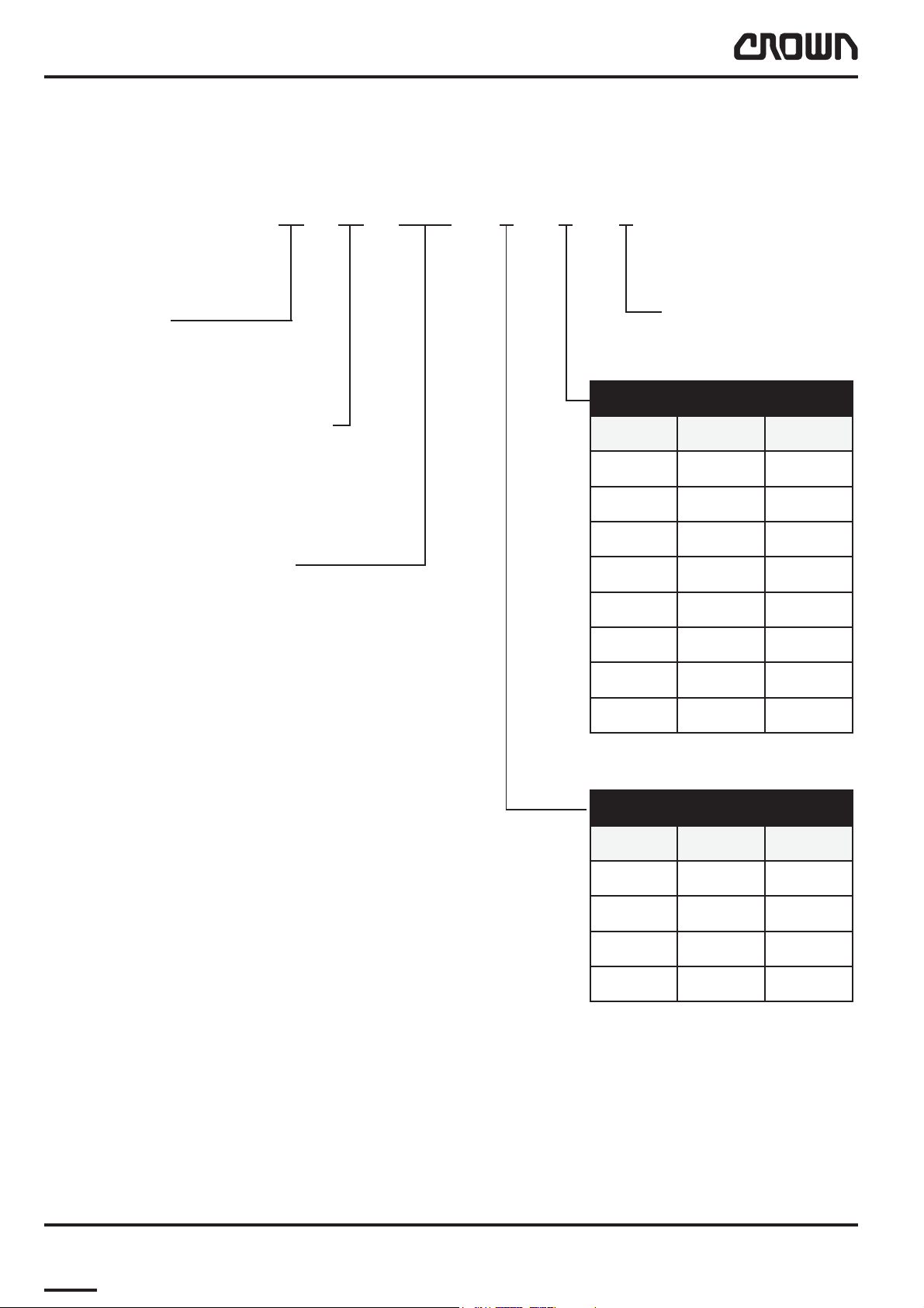
Model-Number
This manual describes the maintenance and repairs for the following truck versions:
2.0 WP 2335S – 3 – 2 – S
Capacity
2.0 = 2000 kg
Model Description
WP = Electric Pedestrian Pallet Truck
Platform T ype
2335 = Fixed Platform
2330 = Folded Platform
Load Wheels
S = Single
T = Tandem
htgneLkroF
hsaD mm hcni
163
2599
324
45211
564
6012184
745
806
daerpSkroF
hsaD mm hcni
181
202502
304522
407672
I02a-gb
I03a-gb
MS-WP2300S-GB 05/03 • Printed in GermanyMS-ITD-1723
8M1.0-0000-00088

LUBRICATION AND ADJUSTMENT
Printed in Germany
9

Blank Page
Printed in Germany
M1.0-0000-00010M1.0-0000-0001010
LUBRICATION AND ADJUSTMENT
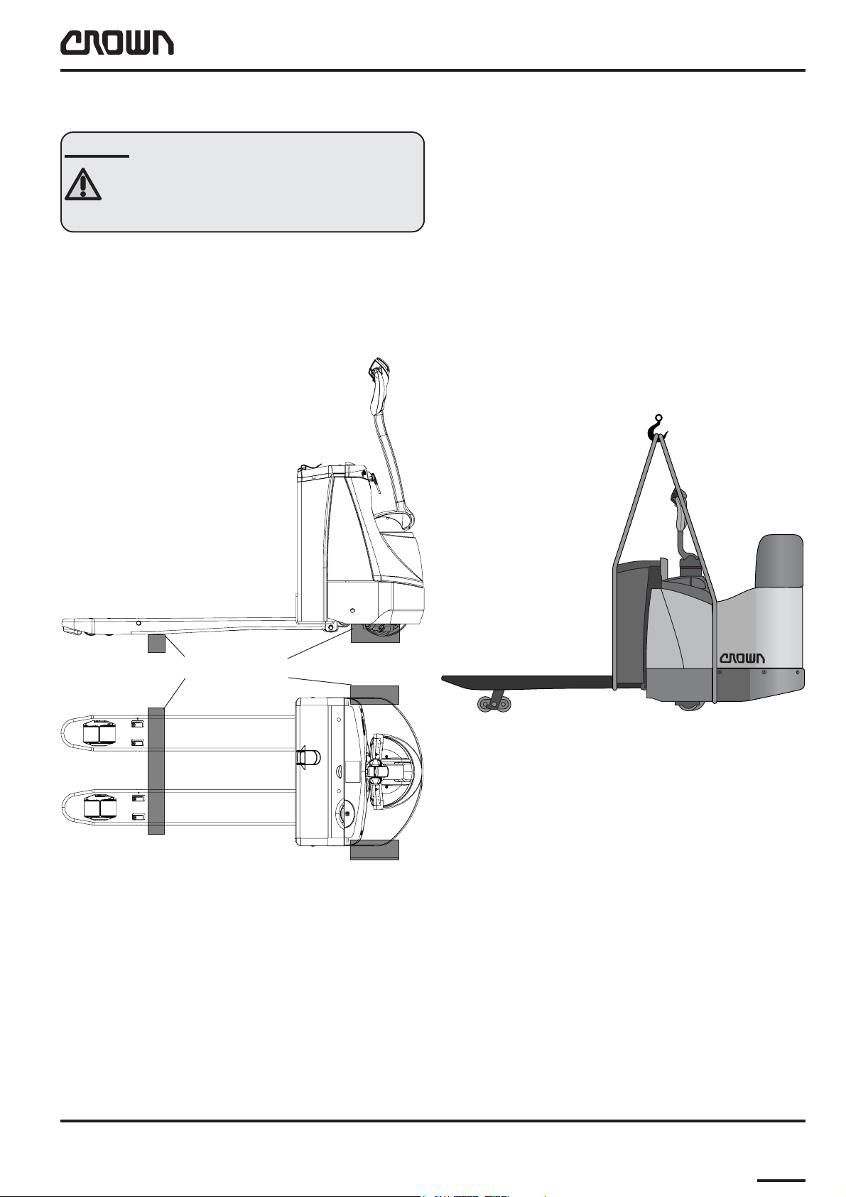
Jacking up the Truck
CAUTION
Always support a raised truck with wooden
blocks or other suitable means to relieve
the jack.
The term "jacking up the truck" always implies that the
raised truck is lowered onto a secure base.
Raising the Truck with a Crane
Fixed Platform
Fit the chains or lifting slings as shown in the diagram:
● to each fork tip with a lifting sling tied around the
platform,
or
● with one hook on each side of the platform.
Capacity required: 600 kg for the WP 2300 S less
battery.
Jack up Points
MS1723-100
M1458-a
MS-WP2300S-GB 05/03 • Printed in Germany
MS-1.0-1723
M-1.0-0000-0001111

LUBRICATION AND ADJUSTMENT
Folding Platform
Fit the chains or lifting slings as shown in the diagram:
● to each fork tip with a lifting sling tied around the
platform.
Prevent the lifting sling from sliding off: connect it
to the forks, see dashed line S.
or
● Attach a hook to points R and L respectively on
the truck frame.
Prevent accidental sliding off: connect the two
chains or lifting slings, see dashed line H,
between the truck and the gates.
Capacity required: 570 kg for the WP 2300 S less
battery.
MS-1.0-1723
M-1.0-0000-0001212
S
R
R
L
MS-WP2300-GB 05/03 • Printed in Germany
H
L
MS-1723-101
LUBRICATION AND ADJUSTMENT
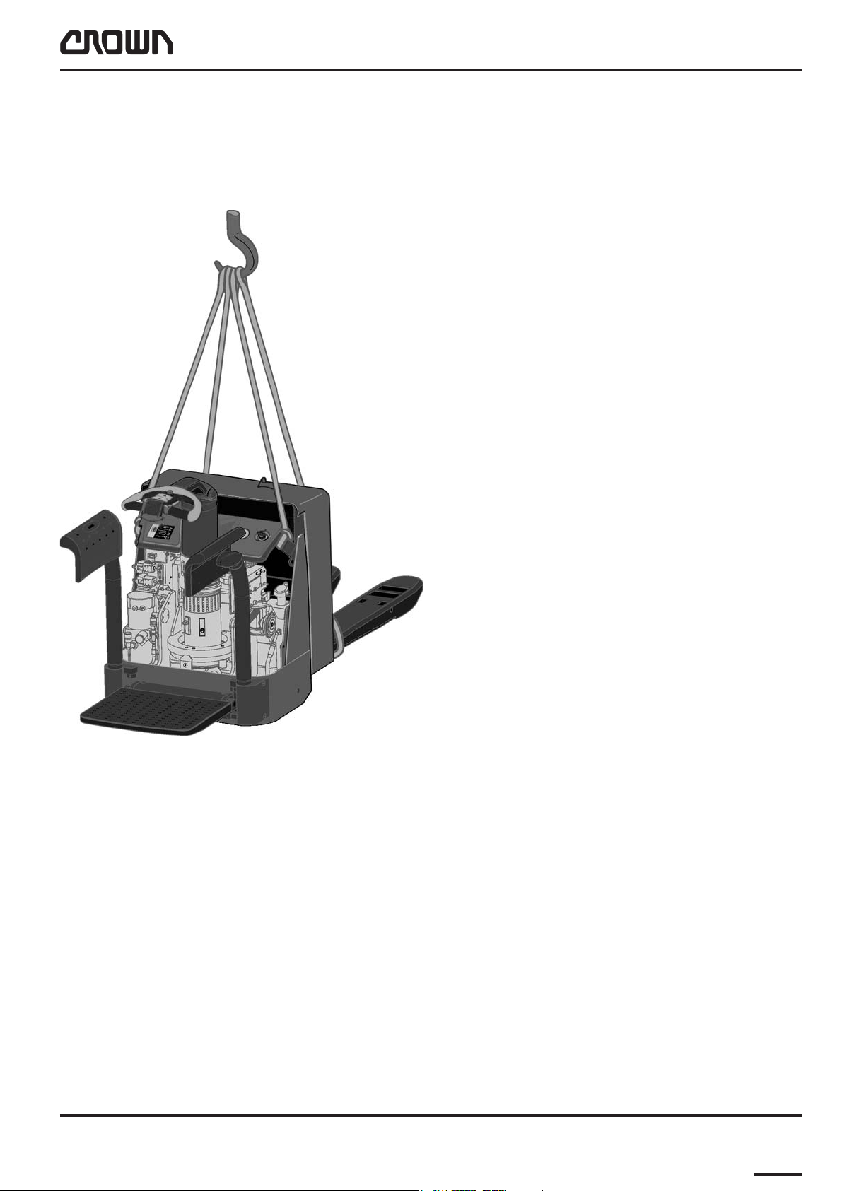
Both Platforms
It is also possible to raise the truck (with either folding
or fixed platform, after removing the panel) as shown in
the following illustration.
MS-WP2300S-GB 05/03 • Printed in Germany
MS-1723-102
MS-1.0-1723
M-1.0-0000-0001313
LUBRICATION AND ADJUSTMENT
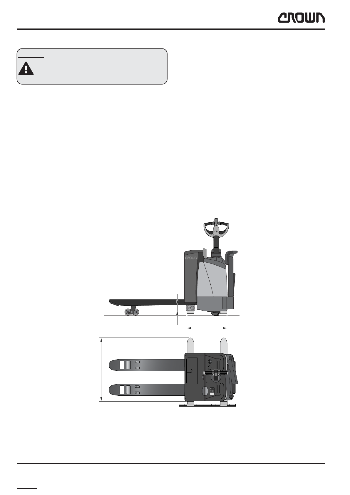
Raising with a Forklift Truck
DANGER
Use a truck with sufficient capacity and
prevent the truck on the forks from sliding
off.
The WP 2300 S can be raised at an angle using a
forklift truck - see illustration.
Required capacity: 600 kg for the WP 2300S less
battery.
● The forks must be fully raised.
● Position the forks of the lifting truck as shown in
the illustration.
● Place a wooden block approx. 90 mm thick
between the forks of the WP 2300S and the fo rk s
of the lifting truck.
● Secure the WP 2300S on the forks of the lifting
truck (e.g. with an elastic strap).
90
600
MS-1.0-1723
M-1.0-0000-0001414
> 800
WP
2300
MS-1723-103
MS-WP2300-GB 05/03 • Printed in Germany
LUBRICATION AND ADJUSTMENT
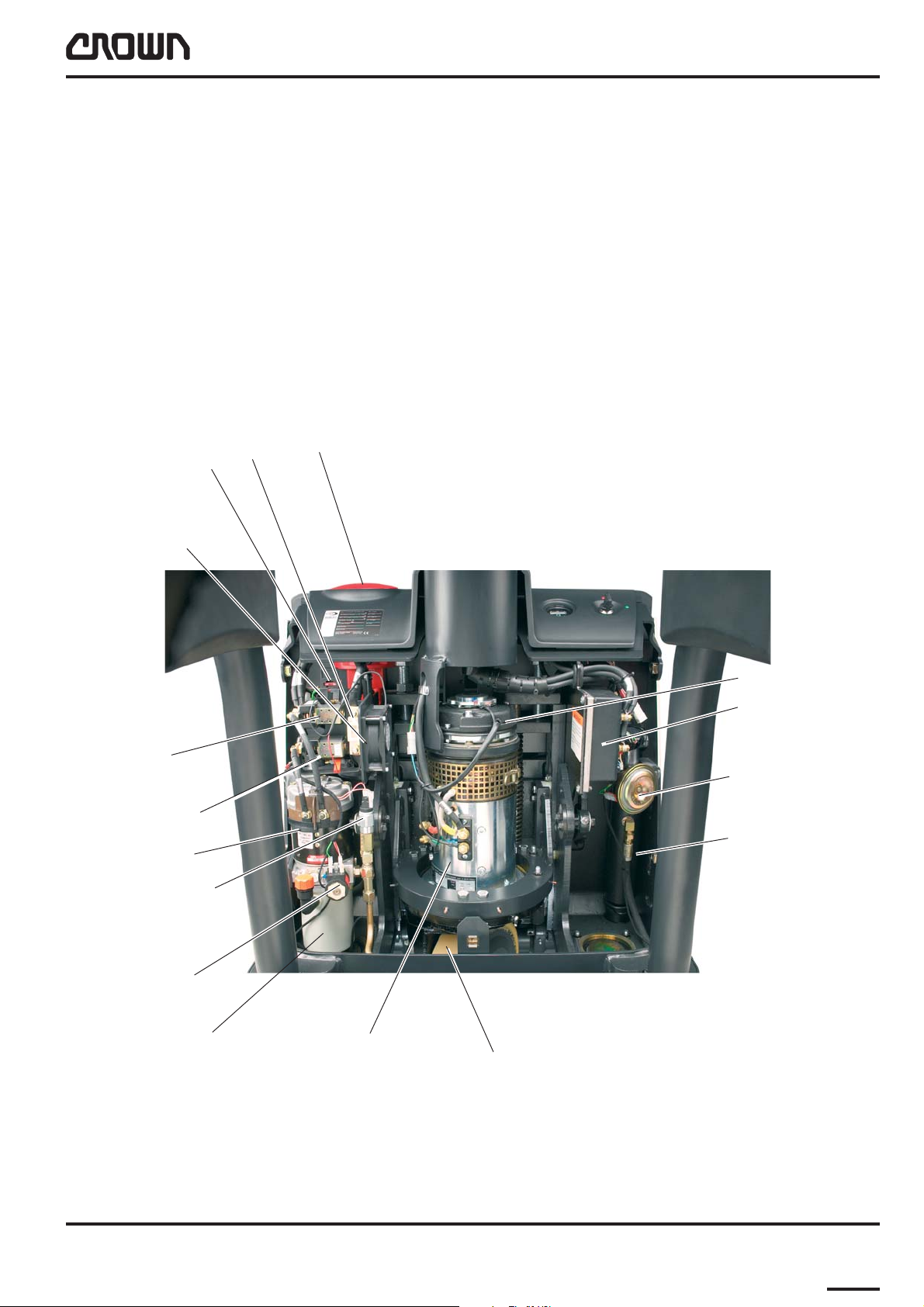
Component Access and Components
Removing the panel provides access to the drive unit,
hydraulic system, contactors, traction controller etc.
The panel is fixed to the frame by two screws.
Removing the screws allows you to slightly lift the
panel up out of the lower retaining lug, tilt it away and
remove it via the tiller.
Battery connector
(EMERGENCY
FU2 - FU3 F/C
FU1
DISCONNECT)
Fan
Main contactor
Pump contactor
Pump motor
Pressure switch
PS
Lowering
valve SV
Magnetic brake
Traction
controller
Horn
Lift cylinder (LH)
MS-1723-120
Hydraulic tank and
pump
MS-WP2300S-GB 05/03 • Printed in Germany
Traction motor
Drive wheel
MS-1.0-1723
M-1.0-0000-0001515
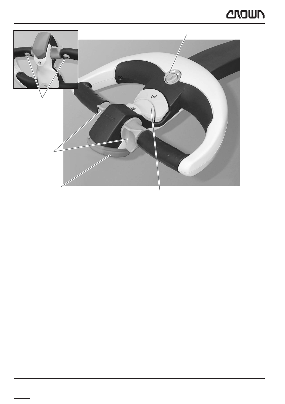
LUBRICATION AND ADJUSTMENT
Button, Horn
Travel Switch
Fast / Slow Travel Switch
Reverse Safety Switch
Lift / Lower Switch
MS1723-004
MS-1.0-1723
M-1.0-0000-0001616
MS-WP2300-GB 05/03 • Printed in Germany

LUBRICATION AND ADJUSTMENT
Blank Page
MS-WP2300S-GB 05/03 • Printed in Germany
M-1.0-0000-0001717

LUBRICATION AND ADJUSTMENT
Maintenance
Recommended Lubricants and Oils
Lubricants
The following page lists typical lubricants which are
also used by Crown in the factory. However, any
lubricants with the same technical specifications can
be used.
Cold Store Trucks
Special hydraulic oil, lubricant oils and grease for low
temperature applications must be used for cold store
trucks (see table on following page). All screws, washers, nuts, pins, retaining rings etc. must be treated
regularly with an anti-corrosion solution CROWN no.
805236-004. Electrical connections and components
must be carefully protected against corrosion. For more
details refer to chapter 4.
Maintenance intervals must be adapted to the conditions of use. They should be as frequent as possible to
prevent excess wear.
● Every 3 months connect the battery, carry out a
daily check and test the truck functions. Then
disconnect the battery again.
Restoring the Truck to Service
When restoring the truck to service, proceed as
follows:
● Remove any addition corrosion protection applied
(except for cold store protection)*.
● Jack up the truck, remove the wooden blocks and
lower the truck.
● Charge the battery or install a charged battery.
● Connect the batter y.
● Carry out the daily check.
*) Do not use high pressure cleaners and/or
solvents on the truck. Do not use metal brushes.
Do not wet-clean the electrical system and do not
use flammable cleaning solutions.
Truck Decommissioning
When taking the truck out of service for more than 3
months, proceed as follows:
● Disconnect the battery.
● Decommission the battery in accordance with the
manufacturer's instructions.
● Clean the tr uck*). Wipe off any grease in
accordance with the maintenance manual.
● If the truck is to be stored in hostile ambient
conditions (e.g. saline atmosphere) treat the
surfaces of the truck with a suitable solution to
prevent corrosion.
● Do not park the truck in the open air or in a
humid environment. The ideal location is a dry
room with as constant a temperature and air
humidity as possible. If the truck has to be
covered, use material through which air can
permeate rather than plastic sheets. Otherwise
condensation water may form.
● Jack up the truck. Lower the chassis onto suitable
wooden blocks in order to clear the wheels from
the ground (this prevents the wheels from
flattening under constant pressure).
M-1.0-0000-0001818
MS-WP2300S-GB 05/03 • Printed in GermanyMS-1.1-1723
 Loading...