

Crown WP2300 Series Maintenance Manual

Maintenance Manual
WP2300 Series
MS-WP2300 04/03 • Printed in Germany
Order Number: 812528-006

This master maintenance manual is subject to continual updates.
It is meant exclusively for businesses authorized by CROWN.
It is not permitted to pass on the contents or copies thereof to third parties.
CRO WN Gabelstapler GmbH & Co. KG
- European Headquarter -
Moosacher Str. 52
80809 Munich
Germany
Phone +49 (0)89 93 00 2 – 0
Fax +49 (0)89 93 00 2 – 133
All rights reserved under international and Pan-American Copyright Agreement.
CROWN Equipment Corporation
Copyright 2002

Overview of Revisions:
Page 3 Rev.1 04/00 General corrections and additions to the text.
Reference to authorised service personnel added.
REVISION
MS-WP2300-GB 04/03 • Printed in Germany MS-REV-1723
M1.0-0000-000AA

Page intentionally left blank
Printed in Germany
B

Printed in Germany
TABLE OF CONTENT
I

Page intentionally left blank
Printed in Germany
M1.0-0000-000IIM1.0-0000-000IIII

TABLE OF CONTENT
Table of Content
ITD – INTRODUCTION PAGE SER-NR. CUT REV.
Safety Symbols used in the Manual .................................. 3 ............................................................... Rev.1 04/00
General Maintenance and Repair Safety Notes ................ 3
Maintenance and Repair .................................................. 3 ............................................................... Rev.1 04/00
Before Leaving the Truck.................................................. 4
Before Carrying out Work on the Truck ............................ 4
Before Operating the Truck............................................... 4
Warnings and Labels on the Truck..................................... 4
General................................................................................. 7
Operating Instructions ...................................................... 7
Service Training................................................................ 7
Ordering Spare Parts ....................................................... 7
Using the Manual ............................................................. 7
Model-Number ..................................................................... 8
M1 – LUBRICATION AND ADJUSTMENT PAGE SER-NR. CUT REV.
Component Access............................................................. 11
Jacking up the Truck ........................................................... 11
Lifting by Crane................................................................... 11
Lifting by Truck ................................................................. 12
Components ........................................................................ 13
Maintenance ........................................................................ 16
Recommended Lubricants and Oils ................................. 16
Lubricants ................................................................... 16
Cold Store Trucks........................................................ 16
Truck Decommissioning ..................................................... 16
Restoring the Truck to Service ........................................... 16
Check and Maintenance Schedule..................................... 18
Safety Reverse Switch – Functional Test .......................... 20
Grease items and grease intervals .................................... 28
Castors................................................................................. 30
Torques ................................................................................ 31
M2 – HYDRAULICS PAGE SER-NR. CUT REV.
Hydraulic Symbols .............................................................. 35
Hydraulic System ................................................................ 39
Operation ......................................................................... 39
Removing the Hydraulic Unit............................................ 40
Replacing the Hydraulic Pump......................................... 41
Removal...................................................................... 41
Installation................................................................... 41
Commissioning and Bleeding the System........................ 41
Filters ............................................................................... 43
Replacing the Pressure Filter...................................... 43
Replacing the Suction and Return Filters.................... 43
Oil Change ....................................................................... 43
Replacing the Safety Valve............................................... 44
Safety Valve Setting ......................................................... 44
Safety Valve T est and Setting ...................................... 44
M3 – DRIVE UNIT PAGE SER-NR. CUT REV.
Gear Unit .............................................................................. 47
Drive Unit, General .............................................................. 48
Removing the Drive Unit..................................................... 48
MS-WP2300-GB 04/03 • Printed in Germany
III

TABLE OF CONTENT
M3 – DRIVE UNIT PAGE SER-NR. CUT REV.
Traction Motor Removal ................................................... 48
Dismantling the Motor ...................................................... 49
Assembling the Motor ...................................................... 49
Traction Motor Assembly .................................................. 51
Gear Unit Disassembly .................................................... 52
General ....................................................................... 52
Preparation ................................................................. 52
Draining the oil ............................................................ 52
Removing the drive unit .............................................. 52
Dismantling the gear unit lid........................................ 52
Dismantling the gear unit ............................................ 53
Gear Unit Assembly .................................................... 53
Installing the gear unit lid ............................................ 55
Adding Oil ................................................................... 55
Installing the drive unit ..................................................... 55
M4 – ELECTRICS PA GE SER-NR. CUT REV.
Electrics - General............................................................... 59
Wire Colour Codes........................................................... 59
Abbreviations ................................................................... 60
Electrical Symbols............................................................ 62
Electrical Components ....................................................... 63
Transmitter (POT, FS, RS) ................................................ 63
Fast / Slow Travel Switch (HSS) ....................................... 63
Reverse Safety Switch (SAS)........................................... 63
Brake Switch (BRS).......................................................... 63
Override Switch (ORS)..................................................... 63
Raise / Lower Switch (RAS, LOS).................................... 64
Limit Switch (LMS) ........................................................... 64
Horn Switch (HNS)........................................................... 64
Key Switch (KYS)............................................................. 64
Emergency Disconnect .................................................... 64
Fuses (FU) ....................................................................... 64
OPTION
Thermal Switch (THS) ........................................... 65
Battery.................................................................................. 67
General ............................................................................ 67
Replacing the battery ....................................................... 67
Battery Discharge Indicator (BDI)...................................... 67
General ............................................................................ 67
Battery Discharge Indicator Setting (BDI) ........................ 68
Calibration ........................................................................ 68
SEM0 T raction Controller .................................................... 67
General ............................................................................ 67
Precautionary Measures ............................................. 67
Operational Features ....................................................... 67
Speed Control ............................................................. 67
Reduced Speed Ranges............................................. 67
Downhill Speed Control............................................... 67
Regenerative Braking.................................................. 67
Anti - Roll Down Function............................................ 67
Hourmeter ................................................................... 68
Self Test ...................................................................... 68
Monitored Circuits ....................................................... 68
Protective Devices............................................................ 68
Polarity Protection....................................................... 68
Wiring Errors ............................................................... 68
Temperature ................................................................ 68
Start Sequence ........................................................... 68
IV
MS-WP2300-GB 04/03 • Printed in Germany

TABLE OF CONTENT
M4 – ELECTRICS PAGE SER-NR. CUT REV.
Safety Class................................................................ 68
Maintenance .................................................................... 69
Replacing the SEM0 Traction Controller........................... 70
Parameter Setting
after Replacing the Traction Controller ............................. 70
Preparatory Measures ................................................ 70
Setting......................................................................... 70
Status LED.................................................................. 72
Programmer......................................................................... 73
General ............................................................................ 73
Operating SEM0 Controller Menu .................................... 74
General ....................................................................... 74
Operating Menu - Overview ........................................ 75
Menu Functions .......................................................... 75
PARAMETER CHANGE .............................................. 75
Settings and Alarms............................................................ 76
TESTER Menu ................................................................. 77
ALARMS Menu ................................................................ 78
PROGRAM VACC Menu .................................................. 79
Calibrating the Traction Pod Potentiometer,
PROGRAM VACC menu .................................................. 81
Preparatory Measures ................................................ 81
Calibration................................................................... 81
CONFIG Menu...................................................................... 82
SET MODEL .................................................................... 82
SET OPTIONS ................................................................. 82
Adjustments ..................................................................... 82
Traction Controller Safety T est ........................................... 83
Battery.................................................................................. 85
General ............................................................................ 85
Replacing the battery ....................................................... 85
Battery Discharge Indicator (BDI)...................................... 85
General ............................................................................ 85
Battery Discharge Indicator Setting (BDI) ........................ 86
Calibration........................................................................ 86
On Board Charger ............................................................... 87
General ............................................................................ 87
Battery Charging Phases ............................................ 87
Special Charging Phases............................................ 87
Charging Errors................................................................ 88
Green LED is not lit ..................................................... 88
Green LED flashing..................................................... 88
Important T echnical Data ................................................. 89
Replacing the Charger ..................................................... 89
Removal / Installation.................................................. 89
Electric Motors .................................................................... 91
General Maintenance Instructions ................................... 91
Preparation ................................................................. 91
Important Maintenance Instructions ............................ 91
Traction Motor Maintenance............................................... 92
Access to Brushes ........................................................... 92
Maintenance .................................................................... 92
Armature ..................................................................... 92
Bearings...................................................................... 92
Pump Motor Maintenance................................................... 93
Access to brushes............................................................ 93
Maintenance .................................................................... 93
Armature ..................................................................... 93
MS-WP2300-GB 04/03 • Printed in Germany
V

TABLE OF CONTENT
M5 – BRAKE PAGE SER-NR. CUT REV.
Brake .................................................................................... 97
Operation ......................................................................... 97
Removal........................................................................... 97
Assembly.......................................................................... 99
Air Gap Setting................................................................. 99
Brake Moment Setting...................................................... 99
Testing the Brakes............................................................ 99
M6 – STEERING PAGE SER-NR. CUT REV.
Live Ring Bearing................................................................ 103
Disassembly..................................................................... 103
Installation ........................................................................ 103
Multitask Handle - Springs for Return Function ............... 104
Adjustment ....................................................................... 104
Removal........................................................................... 104
Assembly.......................................................................... 104
Tiller Handle......................................................................... 105
Main Components ............................................................ 105
Tiller Handle Component Removal / Installation .............. 106
Tiller Handle Shells .......................................................... 106
Removing the Upper and Lower Shells....................... 106
Fitting the Upper and Lower Shells ............................. 107
Switch Unit ....................................................................... 108
Removal...................................................................... 108
Switch Unit Installation ................................................ 108
"Fast/Slow" Toggle Switch ................................................ 109
Removal...................................................................... 109
Installation................................................................... 109
Hydraulic Board ................................................................ 109
Removal...................................................................... 109
Installation................................................................... 109
Potentiometer................................................................... 110
Removal...................................................................... 110
Installation................................................................... 110
Safety Reverse Switch ..................................................... 111
Removal...................................................................... 111
Installation................................................................... 111
Horn Switch...................................................................... 112
Removal...................................................................... 112
Installation................................................................... 112
Handle.............................................................................. 113
Removal...................................................................... 113
Installation................................................................... 113
M7 – LIFTING MECHANISM PAGE SER-NR. CUT REV.
Lift Linkage .......................................................................... 117
Fork Height Setting .......................................................... 117
M8 – CYLINDERS PAGE SER-NR. CUT REV.
Lift Cylinders ....................................................................... 121
Operation ......................................................................... 121
Removal........................................................................... 121
Inspection......................................................................... 123
Replacing the Piston Seal ................................................ 123
MS-WP2300-GB 04/03 • Printed in Germany
VI

TABLE OF CONTENT
DIA – ELECTRICAL DIAGRAMS PAGE SER-NR. CUT REV.
Overall Wiring Diagram, Standar d Version........................ 127
Overall Wiring Diagram with Options ................................ 128
Wire harness overview, all versions .................................. 129
HYD – HYDRAULIC SCHEMATIC PAGE SER-NR. CUT REV.
Hydraulic Schematic ........................................................... 133
MS-WP2300-GB 04/03 • Printed in Germany
VII

Page intentionally left blank
VIII
Printed in Germany

Printed in Germany
SAFETY
1

Page intentionally left blank
Printed in Germany
M1.0-0000-0002M1.0-0000-00022
SAFETY
Safety Symbols used in the Manual
To help guide you through the manual and to highlight
particular danger areas, we have used graphic illustrations:
DANGER
This symbol indicates life-threatening risks
●
Failure to comply with this notice ma y
result in severe or fatal injuries to yourself
or other people.
WARNING
This symbol indicates the risk of serious
injury and/or serious material damage.
●
Failure to comply with this notice ma y
result in severe injuries to yourself or other
people and/or serious material damage.
CAUTION
This symbol indicates the risk of minor
injury and/or minor material damage.
●
Failure to comply with this notice ma y
result in minor injuries to yourself or other
people and/or minor material damage.
General Maintenance and Repair Safety Notes
DANGER
Read the safety notices in the truck Maintenance and Operator's Manuals.
●
Failure to do so could result in severe or
fatal injuries to maintenance personnel
and/or other persons.
Motorised vehicles can be dangerous if maintenance
and service are neglected. For this reason maintenance
and inspections must be carried out at regular short
intervals by trained personnel working to approv ed
company guidelines.
DANGER
Follow all national/local safety regulations
applicable for maintenance work, e.g. f or
work on higher levels.
●
Failure to do so could result in severe or
fatal injuries to maintenance personnel
and/or other persons.
Maintenance and Repair
1. Maintenance work must only be carried out in
accordance with the test and maintenance program contained in the present Maintenance
Manual and any applicable service notices.
INFORMATION
Contains additional information with
supplementary notes and hints.
OPTION
These items relate to optional features not
OPTION
supplied with the standard version.
2. Only qualified and authorised personnel may
carry out work on the truck.
3. Always k eep fire extinguishers in good working
condition. Do not approach fluid levels or leaks
with a naked flame.
4. To clean, use a non flammable, non combustible
cleaning solution which is groundwater-neutral.
Only carry out cleaning with an oil separator.
Protect the electrical system from dampness.
5. Keep the service area clean, dry and well-ventilated.
6. Do not allow oil to penetrate the ground or enter
the draining system. Used oil m ust be recycled.
Oil filters and desiccants must be treated as
special waste products. Rele v ant applicable
regulations must be followed.
7. Neutralise and thoroughly rinse any spilled
battery fluid immediately .
MS-WP2000-GB 04/03 • Printed in Germany
MP/MS-0000-MA
REV. 1 4/00
33

SAFETY
8. Keep the truck clean. This will f acilitate the location of loose or faulty components.
9. Make sure that capacity and data plates, warnings and labels are legible at all times.
10. Alterations or modifications by the owner or
operator are not permitted without the express
written authorisation from Crown.
11. Only use original Crown spare parts to ensure the
reliability, safety and suitability of the Crown truck.
Before Leaving the Truck
● Stop the truc k.
● Lower the fork carriage fully.
● Apply the parking brake.
● T urn off the truck and remove the k ey.
● Block all wheels when parking on an uneven
surface.
Warnings and Labels on the Truck
During regular maintenance check that the warnings
and labels on the truck are complete and legible.
● Clean any illegible labels.
● Replace any faulty or missing labels.
The order and meaning of the warnings and labels on
the truck are described in section 10.9 of the parts
manual.
Before Carrying out Work on the Truck
● Raise the truc k to free the drive wheel. Press the
emergency Stop button and disconnect the
battery.
● Prevent the truck from rolling away.
● Before carrying out work on the hoist frame, the
lift mast or on the fork carriage: Block these parts
according to maintenance instructions in order to
prevent them from dropping.
● Only carry out operational testing when there is
sufficient room to manoeuvre, to avoid the risk of
injury to yourself and others.
Before Operating the Truck
● Check the safety devices.
● Get into the dri v er's seat.
● Check the operation of the lifting device, travel
direction switch, speed control, steering, warning
devices and brakes.
MP/MS-0000-MA
44
MS-WP2000-GB 04/03 • Printed in Germany
REV. 1 4/00

Printed in Germany
INTRODUCTION
5

Page intentionally left blank
Printed in Germany
M1.0-0000-0006M1.0-0000-00066

INTRODUCTION
General
The present manual is designed for Customer Service
engineers who wish to familiarise themselves with the
maintenance work required for the various truck components.
It also contains troubleshooting sections which can be
used to identify and remedy truck faults.
INFORMATION
This book is not an operating manual. It is
designed solely for specialist personnel
who have been trained and authorised to
carry out the work described in the
manual.
This manual therefore contains fewer and less detailed
warnings than the Operator's Manual, as the latter is
aimed at persons who have very little or no prior
experience at all.
This information can be found on the truck's data plate.
Only if this information is provided can the order be
processed quickly, correctly and reliably.
Please refer to the Technical Specifications Sheet for the
utilisable loads, technical data and dimensions for
thisseries. Brochures can be obtained from y our CROWN
dealer or from the following address:
CROWN Gabelstapler GmbH & Co.KG
Moosacher Str. 52
80809 Munich
GERMANY
Tel.: +49 (0)89 / 93 002 -0
Fax: +49 (0)89 / 93 002 -175 oder 133
Using the Manual
The manual is divided into sections. The following table
shows how the manual is structured.
ecnanetniaMsnoitceS
Operating Instructions
This manual contains no operating instructions. An
operating instructions manual is supplied with the vehicle.
Additional copies can be ordered as required.
With the help of this manual you and your personnel will
be able to ensure the long service life, operational saf ety
and error free functioning of your CROWN vehicle.
Service T raining
CROWN offers the appropriate vehicle related training
for service personnel. Details on this training can be
obtained from CROWN on request.
Ordering Spare Parts
The maintenance manual does not cover spare parts.
These are listed in a separate manual.
Spare parts can be ordered by quoting:
● The tr uck specification number
noitceS noitpircseD
XDItnetnoCfoelbaT
AMytefaS
DTInoitcudortnI
1MtnemtsujdAdnanoitacirbuL
2MsciluardyH
3MtinUevirD
4MlacirtcelE
5MekarB
6MgnireetS
● The tr uck model number
● The tr uck serial number
MS-WP2300-GB 04/03 • Printed in Germany MS-ITD-1723
7MmsinahceMgnitfiL/tsaM
8MrednilyC
AIDsmargaiDlacirtcelE
DYHcitamehcSciluardyH
A01M-gb
7M1.0-0000-00077
INTRODUCTION
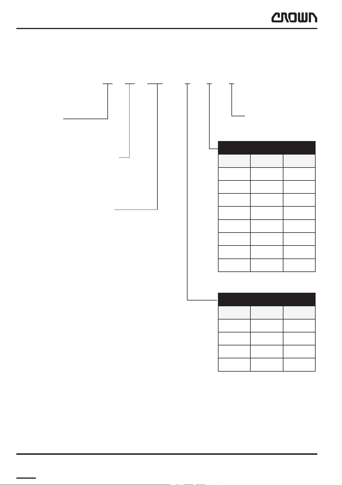
Model-Number
This manual describes the maintenance and repairs for the following truck versions:
1.6 WP 2015 – 3 – 2 – S
Capacity
1.6 = 1600 kg
2.0 = 2000 kg
Model Description
WP = Electric Pedestrian Pallet Truck
Battery Box Size (l x w x h)
2315 = 150 Ah (146 x 660 x 604)
2320 = 240 Ah (212 x 624 x 627)
Load Wheels
S = Single
T = Tandem
htgneLkroF
hsaD mm hcni
163
2599
324
45211
564
6012184
745
806
daerpSkroF
hsaD mm hcni
181
202502
304522
407672
I02a-gb
I03a-gb
MS-WP2300-GB 04/03 • Printed in GermanyMS-ITD-1723
8M1.0-0000-00088

LUBRICATION AND ADJUSTMENT
Printed in Germany
9

Page intentionally left blank
Printed in Germany
M1.0-0000-00010M1.0-0000-0001010
LUBRICATION AND ADJUSTMENT
Component Access
Lifting off the panel will provide access to the drive unit,
hydraulic system, contactors, traction controller etc.
The panel is fixed to the chassis via two screws.
By removing the screws you can lift up the panel from
the lower lugs, tilt and lift it out over the tiller.
Jacking up the Truck
CAUTION
Always support a raised truck with wooden
blocks or other suitable equipment,
thereby relieving the jack.
Please follow the instruction "Jack up the truck" in this
manual by jacking up the truck and supporting it with
wooden blocks.
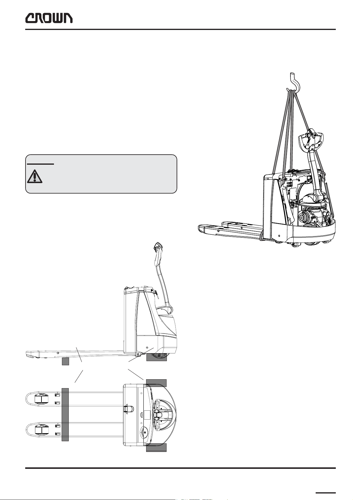
Lifting by Crane
Attach the straps to the hitch points as shown and
prevent them from sliding off.
Jacking Points
MS1723-005
MS-WP2300-GB 04/03 • Printed in Germany
M1458-a
MS-1.0-1723
M-1.0-0000-0001111
LUBRICATION AND ADJUSTMENT
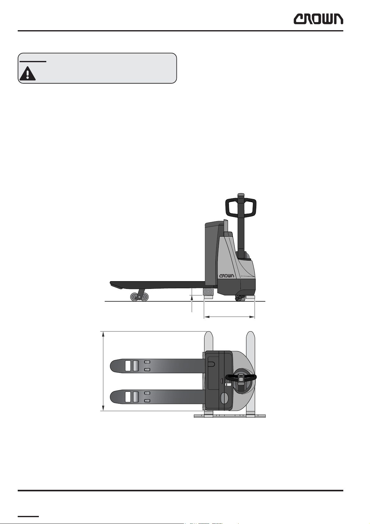
Lifting by Truck
DANGER
Use a forklift with sufficient capacity and
prevent the truck from sliding off the forks.
● Raise the forks to their maximum height.
● Dr ive the forklift sideways underneath the truck
(see diagram).
● Place hard wooden blocks under the truck.
● Secure the tr uck to prevent it from sliding off the
forks.
● Raise the tr uck.
> 800
90
600
WP
2000
MS-1723-002
MS-1.0-1723
M-1.0-0000-0001212
MS-WP2300-GB 04/03 • Printed in Germany
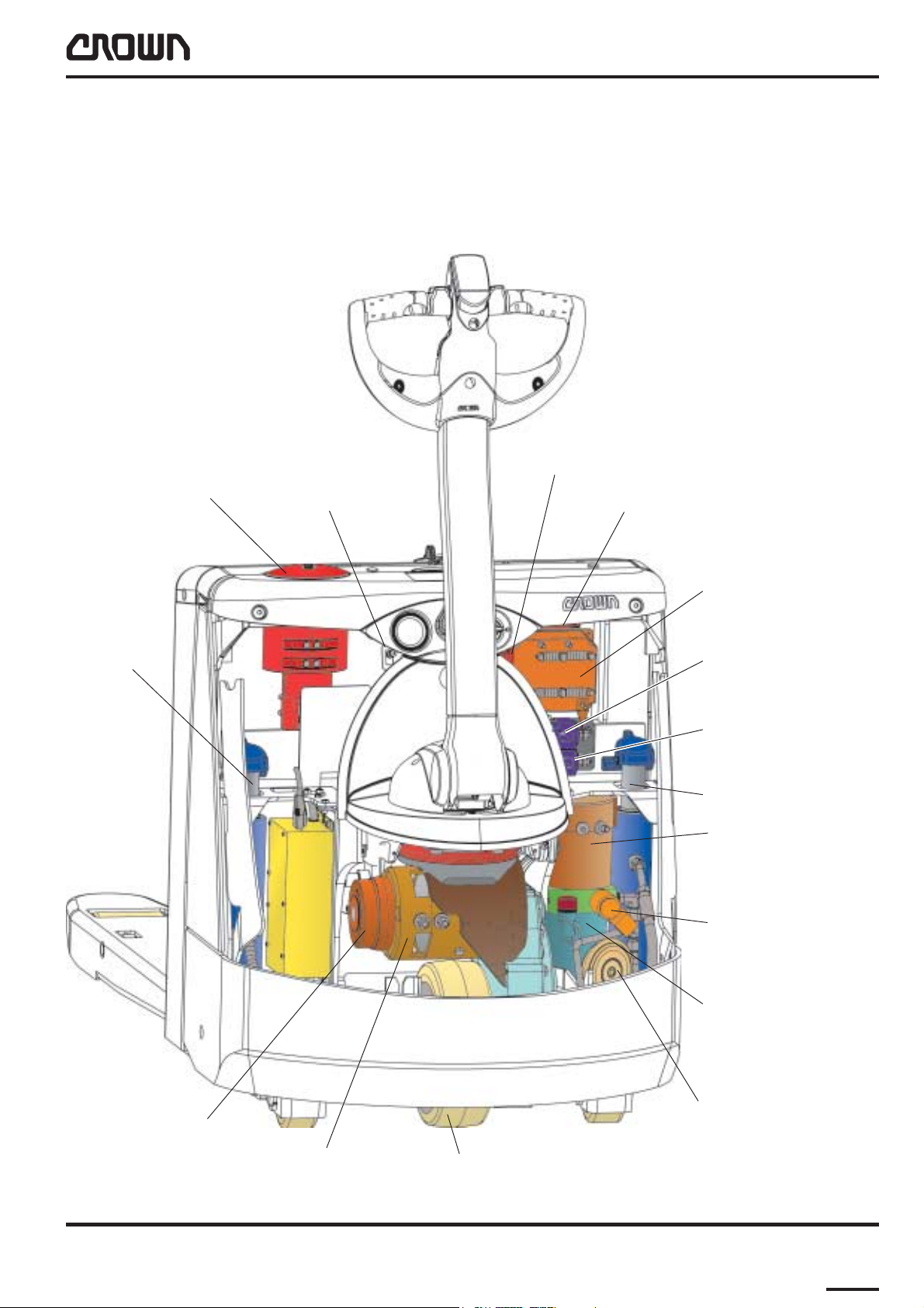
Components
LUBRICATION AND ADJUSTMENT
Battery Connector
(Emergency Disconnect)
Lift Cylinder
RH
FU3 F/C
Control fuse
(Power) Fuse
Traction Controller
Main Contactor
Pump Contactor
Lift Cylinder LH
Pump Motor
Magnetic Brake
Drive Motor
MS-WP2300-GB 04/03 • Printed in Germany
Lowering V alve
Hydraulic Reservoir
with Integrated Pump
Horn
Drive Wheel
M1454-new
MS-1.0-1723
M-1.0-0000-0001313
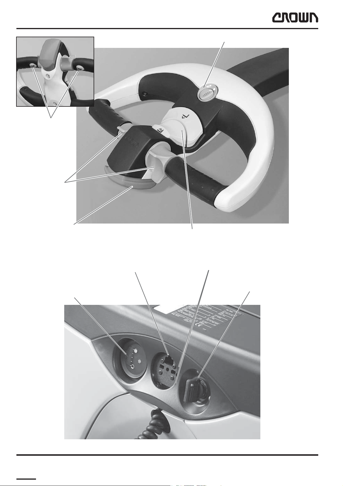
LUBRICATION AND ADJUSTMENT
Button, Horn
Travel Switch
Fast / Slow Travel Switch
Reverse Safety Switch
Socket for storing Charger Plug
Hourmeter and Battery Discharge Display
Lift / Lower Switch
Battery Monitor Displays
MS1723-004
Ke y Switch
MS-1.0-1723
M-1.0-0000-0001414
MS1723-009
MS-WP2300-GB 04/03 • Printed in Germany

LUBRICATION AND ADJUSTMENT
Seite absichtlich freigelassen
MS-WP2300-GB 04/03 • Printed in Germany
M-1.0-0000-0001515

LUBRICATION AND ADJUSTMENT
Maintenance
Recommended Lubricants and Oils
Lubricants
The following page lists typical lubricants which are
also used by Crown in the factory. However, any
lubricants with the same technical specifications can
be used.
Cold Store Trucks
Special hydraulic oil, lubricant oils and grease for low
temperature applications must be used for cold store
trucks (see table on following page). All screws, washers, nuts, pins, retaining rings etc. must be treated
regularly with an anti-corrosion solution CROWN no.
805236-004. Electrical connections and components
must be carefully protected against corrosion. For more
details refer to chapter 4.
Maintenance intervals must be adapted to the conditions of use. They should be as frequent as possible to
prevent excess wear.
● Every 3 months connect the battery, carry out a
daily check and test the truck functions. Then
disconnect the battery again.
Restoring the Truck to Service
When restoring the truck to service, proceed as
follows:
● Remove any addition corrosion protection applied
(except for cold store protection)*.
● Jack up the truck, remove the wooden blocks and
lower the truck.
● Charge the battery or install a charged battery.
● Connect the battery.
● Carry out the daily check.
* Do not use high pressure cleaners and/or
solvents on the truck. Do not use metal brushes.
Do not wet-clean the electrical system and do not
use flammable cleaning solutions.
Truck Decommissioning
When taking the truck out of service for more than 3
months, proceed as follows:
● Disconnect the batter y.
● Decommission the battery in accordance with the
manufacturer's instructions.
● Clean the tr uck*). Wipe off any grease in
accordance with the maintenance manual.
● If the tr uck is to be stored in hostile ambient
conditions (e.g. saline atmosphere) treat the
surfaces of the truck with a suitable solution to
prevent corrosion.
● Do not par k the tr uck in the open air or in a
humid environment. The ideal location is a dry
room with as constant a temperature and air
humidity as possible. If the truck has to be
covered, use material through which air can
permeate rather than plastic sheets. Otherwise
condensation water may form.
● Jack up the truck. Lower the chassis onto suitable
wooden blocks in order to clear the wheels from
the ground (this prevents the wheels from
flattening under constant pressure).
M-1.0-0000-0001616
MS-WP2300-GB 04/03 • Printed in GermanyMS-1.1-1723

LUBRICATION AND ADJUSTMENT
epyTtnacirbuL noitpircseDtcudorP rerutcafunaM .oN-traP-NWORC epyT
2PLHebularA
esaerG-ML
2AsulugeR
)esoprupitlum(esaerG
erutarepmetwoL esaerg
liociluardyH
erutarepmetwoL
liociluardyh
2PE
011B
2PEnocaeB
2PEexuliboM
XLxaniteR
IMWGL
2LKSebularA
PEpmetoLxerinU
23FGmatiV
23-SWAnipsyH
23HotuN
42ETD
23sulleT
23ZLnardyH
23IVHleOztueDrenkcolK900-100350DD
larA
lortsaC
yrutneC
ossE
loxaM
liboM
llehS
FKS
larA
liboM
larA
lortsaC
ossE
liboM
llehS
loniF
shcuF
ekrewlölarniM
HbmG
100-200350B
500-200350BB
300-100350D
09W58pyH
lionoissimsnarT
erutarepmetwoL
lionoissimsnart
09W58D-XG
09/58DHebuliboM
09BMxaripS
426CHSliboMliboM900-200350AA
larA
ossE
liboM
llehS
400-200350A
tcudorP emaNtcudorP noitacilppA .oNtraPnworC
tnegaevisorroc-itnAlytceT
gnitaoctnerapsnarTgnitaoctnerapsnartK2
dnuopmocgnitnioJokriDgnirlE
skcurterotsdloc
.snoitacilppa
roftnegaevisorroc-itnA
tnerapsnarttnatsiserdicA
noitcartrofgnitaoc
erotsdlocrofsrellortnoc
rofdnuopmocgnitnioJ
.)laesdiuqil(diltinuraeg
L01_lubricants_wp-GB
400-632508
300-632508
:egdirtraclm013
200-632508
:ebuTg001
100-632508
L01_adjuvants_WP-GB
MS-WP2300-GB 04/03 • Printed in Germany MS-1.1-1723
M-1.0-0000-0001717

LUBRICATION AND ADJUSTMENT
Check and Maintenance Schedule
The following check and maintenance schedule assumes single-shift operation under normal operating
conditions. The length of maintenance intervals will
however depend on the particular operating conditions.
In dusty or otherwise extreme environments, including
cold stores, the specified maintenance intervals should
be reduced. The exact periods should be established
after consultation with Crown service personnel.
sruohecivres8yreveroyliaD
.oN metI noitcA
1yrettaB
2
3nroHnoitarepokcehC
rotcennoCyrettaB
)potSycnegremE=(
When performing maintenance work always check for
wear, corrosion and damage and ensure that the parts
are operating correctly and are secure. If in doubt,
replace them.
dnaleveletylortcelekcehC.yrettabdegrahcsidaegrahc-eR
.yrassecenfihsinelper
noitarepokcehC
4hctiwsrekcorrewoL/tfiLnoitarepokcehC
5hctiwslevarT)snoitceridhtob(noitarepokcehC
6hctiwslevartwolS/tsaFnoitarepokcehC
7hctiwsytefasesreveRnoitarepokcehC
8ekarB
9gnireetSyalpkcehC
01kroF noitamrofeddnaskcarcfosngiselbisivrofkcehC
11sleehwdaoL/sleehW .ctestnilpslatem,slian,raewrofserytkcehC
21snoitcennocdnasenilciluardyH yrassecenfisnoitcennocnethgit,skaelrofkcehC
ehthtiwgnikarblamronhtob,snoitceridhtob(noitarepokcehC
)gnikarbesrevnidnaeldnahksat-itlum
MS-1.2-1723
M-1.0-0000-0001818
L02-gb
MS-WP2300-GB 04/03 • Printed in Germany
 Loading...