

Page 1

Service Manual
WF3000 Series
Printed in
Germany ● Revision Level A
Order Number: 812556-006
Page 2

This master manual is subject to continual updates.
It is meant exclusively for businesses authorized by CROWN.
It is not permitted to pass on the contents or copies thereof to third parties.
CRO WN Gabelstapler GmbH & Co. KG
- European Headquarter -
Moosacher Str. 52
80809 Munich
Germany
Phone +49 (0)89 93 00 2 - 0
Fax +49 (0)89 93 00 2 - 133
All rights reserved under international and Pan-American Copyright Agreement.
CROWN Equipment Corporation
Copyright 2005
Page 3

Overview of Revisions:
REVISION
WF3000 09/2005 • Printed in Germany MS-REV-3300
A
Page 4

Blank page
Printed in Germany
B
Page 5

Printed in Germany
TABLE OF CONTENTS
3
Page 6

Blank page
Printed in Germany
4
Page 7

TABLE OF CONTENTS
Table of Contents
MA – SAFETY PAGE SER-NO. CUT.................. REV.
Safety Symbols used in the Manual...................................... 3
ITD – INTRODUCTION PA GE SER-N0. CUT REV.
General Maintenance and Repair Safety Notes ................... 3
Maintenance and Repair ................................................ 3
Before Leaving the Truck ................................................ 4
Before Carrying out Work on the Truck.......................... 4
Before Operating the Tr uck ............................................. 4
Warnings and Labels on the Truck........................................ 4
General..................................................................................... 7
Operating Instructions .................................................... 7
Service Training .............................................................. 7
Ordering Spare Parts...................................................... 7
Using the Manual............................................................ 7
Model-Number ......................................................................... 8
M1 – LUBRICATION AND ADJUSTMENT PAGE SER-N0. CUT .................. REV.
Raising And T owing The Truck ............................................... 11
Raising With Another Forklift Truck................................ 11
Lifting by Crane............................................................... 12
Towing the Truck ............................................................. 13
Component Access ................................................................ 14
Maintenance ............................................................................ 16
Recommended Lubricants and Oils .............................. 16
Lubricants ................................................................... 1 6
Cold Store Trucks........................................................ 16
Taking the tr uck out of service ....................................... 16
Bringing the truck back into service .............................. 16
Lubricant T able ........................................................................ 17
Adjuvants T able ....................................................................... 18
T ruck Tilt Settings ................................................................... 22
Testing and Adjusting the Lateral Inclination ................ 22
Lowering Plumb Test ....................................................... 22
M2 – HYDRAULICS PAGE SER-N0. CUT .................. REV.
Hydraulic Symbols.................................................................. 27
Hydraulics................................................................................ 31
Hydraulic Reservoir Capacity ......................................... 31
Changing the Hydraulic oil and
Hydraulic Filter................................................................ 31
Hydraulic system ............................................................ 33
Function........................................................................... 33
Lifting (see diagram) ................................................... 33
Lowering (see diagram) .............................................. 34
MOTOR AND PUMP ASSEMBLY................................... 35
Hydraulic Lines and Fittings ....................................... 35
General Rules for Hydraulic Lines and Connections.. 35
Bleeding the Hydraulic System................................... 35
Drift T est...................................................................... 35
Proportional function:................................................ 35
REMOVAL ....................................................................... 35
MOTOR............................................................................ 3 6
PUMP .............................................................................. 36
After replacing the pump: ......................................... 36
WF3000 09/2005 • Printed in Germany MS-IDX-3300
V
Page 8

TABLE OF CONTENTS
M2 – HYDRAULICS PAGE SER-N0. CUT .................. REV.
Replacing the relief valve....................................................... 37
Relief valve test and setting................................................... 37
Hydraulic System Troubleshooting ................................. 38
M3 – DRIVE UNIT PAGE SER-N0. CUT .................. REV .
Gear Unit.................................................................................. 41
Drive unit, general................................................................... 42
Drive unit removal........................................................... 42
Drive motor removal ....................................................... 42
Motor disassembly.......................................................... 43
Motor assembly ............................................................... 43
Drive motor assembly..................................................... 45
Gear unit disassembly.................................................... 46
General ....................................................................... 46
Preparation ................................................................. 46
Draining the oil............................................................ 46
Drive unit removal....................................................... 46
Gear unit cover removal.............................................. 46
Gear unit disassembly ................................................ 47
Gear unit assembly..................................................... 47
Gear unit cover installation ......................................... 49
Adding Oil ................................................................... 49
Drive unit installation ...................................................... 49
M4 – ELEKTRICS PAGE SER-N0. CUT .................. REV.
Electrics - General .................................................................. 53
Wire Colour Codes ......................................................... 53
Abbreviations .................................................................. 54
Electrical Symbols .......................................................... 57
Electrical Components ........................................................... 58
Traction Pod (POT, FS, RS)............................................ 58
Fast / Slow Travel Switch (HSS)..................................... 58
Safety Reverse Switch (SAS)......................................... 58
Brake Switch (BRS) ........................................................ 58
Override Switch (ORS)................................................... 58
Raise / Lower Switches (RAS, LOS) ............................. 59
Limit Switch (LMS).......................................................... 59
Horn Switch (HNS) ......................................................... 59
Key Switch (KYS)............................................................ 59
Emergency Disconnect (BD).......................................... 59
Fuses (FU) ...................................................................... 59
OPTION
Thermal Switch (THS) ......................................... 59
Thermal switch (THS2)................................................... 5 9
Hydraulic Control Module (HCM)................................... 59
Unigage (BDI) ................................................................. 59
Integrated Charger .......................................................... 59
Plug Holder (PC)............................................................. 5 9
Drive motor (M1)............................................................. 59
Hydraulic Motor (M2) ...................................................... 60
Main Contactor (Line/LC) ............................................... 60
Lift Contactor (P/P1+P2) ................................................ 60
Electromagnetic Brake (BRK) ........................................ 60
Ter minal Board (TB) ....................................................... 60
Travel Alarm Driver (DR) ................................................ 60
Aux. Hydraulic Switch (SLS/SRS).................................. 60
VI
WF3000 09/2005 • Printed in GermanyMS-IDX-3300
Page 9

TABLE OF CONTENTS
M4 – ELEKTRICS PAGE SER-N0. CUT .................. REV.
Remote Control Toggle Switch (ECS)............................ 60
Aux. Hydraulic Valves (SVA1/SVA2) .............................. 60
Horn (HN) ........................................................................ 60
Main Circuit Board (MAIN PCB)..................................... 60
Hydraulic Circuit Board (HYD PCB) ............................... 60
Travel Alarm (ALM) ......................................................... 60
Receiver .......................................................................... 60
Transmitter....................................................................... 6 0
SEM0 T raction Controller........................................................ 64
General............................................................................ 64
Precautionary Measures............................................. 64
Functional Characteristics.............................................. 64
Speed control.............................................................. 64
Reduced speed ranges .............................................. 64
Downhill speed control................................................ 64
Regenerative braking.................................................. 64
Anti Roll Down Function ............................................. 65
Hourmeter................................................................... 65
Self-Diagnostic System ............................................... 65
Monitored Circuits....................................................... 65
Safety Mechanisms......................................................... 65
Incorrect polarity ......................................................... 65
Wiring Errors............................................................... 65
Temperature protection............................................... 65
Start sequence ........................................................... 65
Protection rating.......................................................... 65
Maintenance.................................................................... 66
Replacing the SEM0 Traction Controller............................... 67
Parameter Setting after Replacing
the Traction Controller .................................................... 6 7
Preparatory Measures ................................................ 67
Adjustment.................................................................. 67
Status LED ...................................................................... 69
Programmer............................................................................. 70
General............................................................................ 70
Crown Handset P/N 793548 (Includes Cord) ........... 70
Operating SEM0 Controller Menu.......................................... 71
General............................................................................ 71
Menu structure............................................................ 71
Menu Functions .............................................................. 72
PARAMETER CHANGE.............................................. 72
TEST........................................................................... 72
ALARMS ..................................................................... 7 2
PROGRAM VACC ....................................................... 72
CONFIG ...................................................................... 72
Functions Menu, general................................................ 73
Parameter Change Menus ............................................. 74
Settings and Error Messages......................................... 75
Tester Menu..................................................................... 80
TESTER Menu ................................................................ 81
Alar m s M en u ................................................................... 8 2
ALARMS Menu ................................................................ 83
Calibrating the Traction Pod Potentiometer,
PROGRAM VACC menu................................................. 86
Preparatory Measures ................................................ 86
Calibration................................................................... 86
Conf ig . Menu ................................................................... 8 7
CONFIG Menu ................................................................ 88
WF3000 09/2005 • Printed in Germany MS-IDX-3300
VII
Page 10

TABLE OF CONTENTS
M4 – ELEKTRICS PAGE SER-N0. CUT .................. REV.
SET MODEL ............................................................... 88
SET OPTIONS............................................................ 88
ADJUSTMENTS ......................................................... 88
On Board Charger ................................................................... 89
General............................................................................ 89
Battery Charging Phases ............................................... 89
First Phase (I1) ........................................................... 89
Second Phase (P)....................................................... 89
Third Phase (U) .......................................................... 8 9
Fourth Phase (I2)........................................................ 89
End of Normal Charging ............................................. 90
Special Charging Phases............................................... 90
Compensating Charge................................................ 90
Float Charge ............................................................... 90
Partial Charging .......................................................... 90
Charging Errors ............................................................... 91
Green LED is not lit..................................................... 91
Possible Causes: ...................................................... 91
Green LED flashing .................................................... 91
Important Technical Data................................................ 92
Replacing the Charger ................................................... 92
Removal / Installation.................................................. 92
Electric Motors ........................................................................ 93
General Maintenance Instructions ........................................ 93
Preparation...................................................................... 93
Important Maintenance Instructions ........................... 93
Traction Motor Maintenance (WF 1.0 t) ................................. 94
Access to brushes .......................................................... 94
Maintenance.................................................................... 94
Armature ..................................................................... 94
Bearings...................................................................... 94
Traction Motor Maintenance (WF 1.2 t) ................................. 95
Access to brushes .......................................................... 95
Maintenance.................................................................... 95
Armature ..................................................................... 95
Bearings...................................................................... 95
Pump Motor Maintenance ...................................................... 96
Access to brushes .......................................................... 96
Maintenance.................................................................... 96
Armature.......................................................................... 96
Contactors ............................................................................... 97
Inspection........................................................................ 97
Contacts...................................................................... 97
Coils ............................................................................ 97
Springs........................................................................ 97
Servicing ......................................................................... 98
Dismantling ................................................................. 98
Assembly .................................................................... 98
Hydraulic Control Module (HCM)........................................... 99
Battery Discharge Indicator (BDI) ......................................... 100
OPERATION.................................................................... 100
General............................................................................ 101
Battery Discharge Indicator Setting (BDI) ..................... 101
Calibration for wet batteries ........................................... 1 02
TROUBLESHOOTING.................................................... 103
Traction Controller Safety Test ....................................... 104
VIII
WF3000 09/2005 • Printed in GermanyMS-IDX-3300
Page 11

TABLE OF CONTENTS
M5 – BRAKE PAGE SER-N0. CUT .................. REV .
Brake ........................................................................................ 107
Function........................................................................... 107
Disassembly.................................................................... 107
Assembly......................................................................... 109
Air gap setting ................................................................. 109
Brake moment setting ..................................................... 110
Brake test ........................................................................ 110
Definition of run-in/new rotor ...................................... 110
General Notes............................................................. 110
M6 – STEERING PAGE SER-N0. CUT .................. REV.
Steering.................................................................................... 11 5
Live ring bearing ............................................................. 115
Disassembly ............................................................... 115
Installation................................................................... 115
Control handle return springs ............................................... 116
Adjustment ...................................................................... 116
Disassembly.................................................................... 116
Installation ....................................................................... 116
Steering Chain......................................................................... 117
Permissible Elongation................................................... 11 7
Chain Tension Adjustment.............................................. 117
Tiller Handle ............................................................................ 119
Main Components........................................................... 119
Tiller Handle Component Removal / Installation ................. 120
Tiller Handle Shells......................................................... 120
Removing the Upper and Lower Shells ...................... 120
Fitting the Upper and Lower Shells ............................. 121
Switch Unit ...................................................................... 122
Removal...................................................................... 122
Switch Unit Installation................................................ 122
"Fast/Slo w" Toggle Switch .............................................. 123
Removal...................................................................... 123
Installation................................................................... 123
Hydraulic Board .............................................................. 123
Removal...................................................................... 123
Installation................................................................... 123
Potentiometer.................................................................. 124
Removal...................................................................... 124
Installation................................................................... 124
Safety Reverse Switch.................................................... 125
Removal...................................................................... 125
Installation................................................................... 125
Horn Switch..................................................................... 126
Removal...................................................................... 126
Installation................................................................... 126
Handle ............................................................................. 127
Removal...................................................................... 127
Installation................................................................... 127
WF3000 09/2005 • Printed in Germany MS-IDX-3300
IX
Page 12

TABLE OF CONTENTS
M7 – MAST PAGE SER-N0. CUT .................. REV .
Mast.......................................................................................... 131
General............................................................................ 131
Torque Requirements ................................................. 131
Lifting Gear Minimum Capacity................................... 131
Mast Removal ................................................................. 131
Installation ....................................................................... 132
Fork Carriage Removal .................................................. 132
Fork Carriage Installation............................................... 132
Fork Carriage Adjustment .............................................. 133
Mast Maintenance .......................................................... 134
Lubricating Roller Tracks............................................. 134
Lowering Plumb Test .............................................................. 135
Preparatory measures.................................................... 135
Carrying out the vertical plumb test............................... 135
Lift chains ................................................................................ 136
General............................................................................ 136
Inspection........................................................................ 136
Cleaning...................................................................... 136
Wear ........................................................................... 136
Freedom of Movement of Chain Links ........................ 137
Chain Tension ............................................................. 137
Chain Anchor and Pulleys .......................................... 138
Worn Connection Plates ............................................. 138
Protruding or Turned Chain Pins................................. 138
Corrosion .................................................................... 138
Chain Lateral Wear ..................................................... 13 9
Uneven Chain Tension .............................................. 139
Misaligned Lift Components ..................................... 139
Lift Chain Lubrication...................................................... 140
Separating Lift Chains .................................................... 14 1
Tools and Equipment Required ...................................... 141
Detachment..................................................................... 141
Fork Tines ................................................................................ 142
General............................................................................ 142
Terms .......................................................................... 142
Fork Identification ....................................................... 142
Repairs ............................................................................ 142
Fork Inspection ............................................................... 142
Crack Inspection ......................................................... 142
V erticality Test ............................................................. 143
Fork Blade Warping .................................................... 143
Measuring the Fork Tip Width........................................ 143
Fork Tine Height Difference ........................................... 143
Fork Stop......................................................................... 143
Fork Blade Wear ............................................................. 144
WF3000 09/2005 • Printed in GermanyMS-IDX-3300
X
Page 13

TABLE OF CONTENTS
M8 – CYLINDERS PAGE SER-N0. CUT .................. REV .
Cylinders.................................................................................. 147
General............................................................................ 147
Safety when working on hydraulic systems ................ 147
General Instructions for Repairing Hydraulic
Components ............................................................... 147
Rod Seal Assembly................................................................. 148
General............................................................................ 148
Large Rod Seal Assembly.............................................. 148
Small Seal Rod Assembly .............................................. 149
Rod Seal Assembly, Sealing Lip First............................ 150
Cylinders.................................................................................. 151
TL Mast Lift Cylinder....................................................... 151
Seal Replacement ...................................................... 151
Installing TL Mast Lift Cylinders.................................. 152
TF Mast Lift Cylinders .................................................... 154
Removing the TF Mast Lift Cylinders.......................... 154
Seal Replacement ...................................................... 154
Installing TF Mast Lift Cylinders.................................. 155
Free Lift Cylinder TF and Mono Mast ............................ 156
Seal Replacement ...................................................... 156
Installing Free Lift Cylinder............................................. 157
Cylinder Bleeding and Flushing ..................................... 157
Bleeding — Mast Lift Cylinders................................... 157
Bleeding — Free Lift Cylinder (if applicable) .............. 1 57
Flushing – Mast Lift Cylinders
and Free Lift Cylinders (if applicable) ......................... 158
Drift T est...................................................................... 15 8
Cylinder Shimming .......................................................... 158
Lift Cylinder Shims...................................................... 158
Free Lift Cylinder Shims .............................................. 15 8
DIA – ELECTRICAL DIAGRAMS PAGE SER-N0. CUT .................. REV.
WF 3000-10 Standard.............................................................. 163
Overview.......................................................................... 163
WF3000-10 Standard,
Traction Controller - SEM0 Logic ................................... 164
WF3000-10 Standard,
Traction Controller - SEM0 Power Circuit...................... 165
WF3000-10 Standard,
Power Unit Control Circuit .............................................. 166
WF3000-10 Standard,
Control Handle - Control Circuit..................................... 167
WF3000-10 Standard,
Hydraulic Control Module (HCM)................................... 168
WF3000-10 with Options ........................................................ 169
Overview.......................................................................... 169
WF3000-10 with Options,
Traction Controller - SEM0 Logic ................................... 170
WF3000-10 with Options,
Traction Controller - SEM0 Power Circuit...................... 171
WF3000-10 with Options,
Power Unit - Control Circuit............................................ 172
WF3000-10 with Options,
Control Handle - Control Circuit..................................... 1 73
WF3000-10 with Options,Hydraulic Control Module (HCM)
- Travel Alarm and Flashing Beacon.............................. 174
WF3000 09/2005 • Printed in Germany MS-IDX-3300
XI
Page 14

TABLE OF CONTENTS
DIA – ELECTRICAL DIAGRAMS PAGE SER-N0. CUT .................. REV.
WF 3000-12 Standard.............................................................. 175
Overview.......................................................................... 175
WF3000-12 Standard,
Traction Controller - SEM0 Logic ................................... 176
WF3000-12 Standard,
Traction Controller - SEM0 Power Circuit...................... 177
WF3000-12 Standard,
Power Unit Control Circuit .............................................. 178
WF3000-12 Standard,
Control Handle - Control Circuit..................................... 179
WF3000-12 Standard,
Hydraulic Control Module (HCM)................................... 180
WF3000-12 with Options ........................................................ 181
Overview.......................................................................... 181
WF3000-12 Swith Options,
Traction Controller - SEM0 Logic ................................... 182
WF3000-12 with Options,
Traction Controller - SEM0 Power Circuit...................... 183
WF3000-12 with Options,
Power Unit - Control Circuit............................................ 184
WF3000-12 with Options,
Control Handle - Control Circuit..................................... 1 85
WF3000-12 with Options, Hydraulic Control Module (HCM)
- Travel Alarm and Flashing Beacon.............................. 186
Wire Harness ........................................................................... 187
Control Handle Wiring .................................................... 188
Power Cab les .................................................................. 18 9
HYD – HYDRAULIC SCHEMATICS PAGE SER-N0. CUT .................. REV .
Hydraulik Schematic Standard Lift ....................................... 193
Hydraulik Schematic Soft Lift ................................................ 194
XII
WF3000 09/2005 • Printed in GermanyMS-IDX-3300
Page 15

Printed in Germany
SAFETY
1
Page 16

Blank page
Printed in Germany
2
Page 17
SAFETY
Safety Symbols used in the Manual
T o help guide you through the man ual and to highlight particular danger areas, we have used graphic illustrations:
DANGER
This symbol indicates life-threatening
risks
● Failure to comply with this notice may result in
fatal injuries to yourself or other people.
WARNING
This symbol indicates the risk of serious
injury and/or serious material damage.
● Failure to comply with this notice may result in
severe injuries to yourself or other people and/or
serious material damage.
CAUTION
This symbol indicates the risk of minor
injury and/or minor material damage.
General Maintenance and Repair
Safety Notes
DANGER
Read the safety notices in the truck
Maintenance and Operator's Manuals.
● Failure to do so could result in severe or fatal
injuries to maintenance personnel and/or other
persons.
Motorised vehicles can be dangerous if maintenance and
service are neglected. For this reason maintenance and
inspections must be carried out at regular short intervals
by trained personnel working to approved company guidelines.
DANGER
Follow all national/local safety regulations applicable for maintenance work,
e.g. for work on higher levels.
● Failure to do so could result in severe or fatal
injuries to maintenance personnel and/or other
persons.
● Failure to comply with this notice may result in
minor injuries to yourself or other people and/or
minor material damage.
INFORMATION
Contains additional information with
supplementary notes and hints.
OPTION
These items relate to optional features
not supplied with the standard version.
Maintenance and Repair
1. Maintenance work must only be carried out in
accordance with the test and maintenance
program contained in the present Maintenance
Manual and any applicable service notices.
2. Only qualified and authorised personnel may
carry out work on the truck.
3. Always keep fire extinguishers in good working
condition. Do not approach fluid levels or leaks
with a naked flame.
4. To clean, use a non flammable, non combustible
cleaning solution which is groundwater-neutral.
Only carry out cleaning with an oil separator.
Protect the electrical system from dampness.
5. Keep the service area clean, dry and wellventilated.
6. Do not allow oil to penetrate the ground or enter
the draining system. Used oil must be recycled.
Oil filters and desiccants must be treated as
special waste products. Relevant applicable
regulations must be followed.
7. Neutralise and thoroughly rinse any spilled
battery fluid immediately.
8. Keep the truck clean. This will facilitate the
location of loose or faulty components.
WF3000 09/2005 • Printed in Germany MS-MA-0000
3
Page 18

SAFETY
9. Make sure that capacity and data plates, warnings
and labels are legible at all times.
10. Alterations or modifications by the owner or
operator are not permitted without the express
written authorisation from Crown.
11. Only use original Crown spare parts to ensure
the reliability, safety and suitability of the Crown
truck.
Before Leaving the Truck
● Stop the truck.
● Lower the fork carriage fully.
● Apply the parking brake.
● Turn off the truck and remove the key.
● Block all wheels when parking on an uneven
surface.
Before Carrying out Work on the Truck
● Raise the truck to free the drive wheel. Press the
emergency Stop button and disconnect the
battery.
Warnings and Labels on the Truck
During regular maintenance check that the warnings and
labels on the truck are complete and legible.
● Clean any illegible labels.
● Replace any faulty or missing labels.
The order and meaning of the warnings and labels on
the truck are described in section 10.9 of the parts
manual.
● Prevent the truck from rolling away.
● Before carrying out work on the hoist frame, the
lift mast or on the fork carriage: Block these parts
according to maintenance instructions in order to
prevent them from dropping.
● Only carry out operational testing when there is
sufficient room to manoeuvre, to avoid the risk of
injury to yourself and others.
Before Operating the Truck
● Check the safety devices.
● Get into the driver's seat.
● Check the operation of the lifting device, travel
direction switch, speed control, steering, warning
devices and brakes.
WF3000 09/2005 • Printed in GermanyMS-MA-0000
4
Page 19

Printed in Germany
INTRODUCTION
5
Page 20

Blank page
Printed in Germany
6
Page 21

INTRODUCTION
General
The present manual is designed for Customer Service
engineers who wish to familiarise themselves with the
maintenance work required for the various truck components.
It also contains troubleshooting sections which can be
used to identify and remedy truck faults.
INFORMATION
This book is not an operating manual. It is
designed solely for specialist personnel
who have been trained and authorised to
carry out the work described in the
manual.
This manual therefore contains fewer and less detailed
warnings than the Operator's Manual, as the latter is
aimed at persons who have very little or no prior
experience at all.
This information can be found on the truck's data plate.
Only if this information is provided can the order be
processed quickly, correctly and reliably.
Please refer to the Technical Specifications Sheet for the
utilisable loads, technical data and dimensions for
thisseries. Brochures can be obtained from y our CROWN
dealer or from the following address:
CROWN Gabelstapler GmbH & Co.KG
Moosacher Str. 52
80809 Munich
GERMANY
Tel.: +49 (0)89 / 93 002 -0
Fax: +49 (0)89 / 93 002 -175 or133
Using the Manual
The manual is divided into sections. The following table
shows how the manual is structured.
ecnanetniaMsnoitceS
Operating Instructions
This manual contains no operating instructions. An
operating instructions manual is supplied with the vehicle.
Additional copies can be ordered as required.
With the help of this manual you and your personnel will
be able to ensure the long service life, operational saf ety
and error free functioning of your CROWN vehicle.
Service T raining
CROWN offers the appropriate vehicle related training
for service personnel. Details on this training can be
obtained from CROWN on request.
Ordering Spare Parts
The maintenance manual does not cover spare parts.
These are listed in a separate manual.
Spare parts can be ordered by quoting:
● The truck specification number
noitceS noitpircseD
XDItnetnoCfoelbaT
AMytefaS
DTInoitcudortnI
1MtnemtsujdAdnanoitacirbuL
2MsciluardyH
3MtinUevirD
4MlacirtcelE
5MekarB
6MgnireetS
● The truck model number
● The truck serial number
WF3000 09/2005 • Printed in Germany MS-ITD 3300
7MmsinahceMgnitfiL/tsaM
8MrednilyC
AIDsmargaiDlacirtcelE
DYHcitamehcSciluardyH
A01M-gb
7M1.0-0000-00077
Page 22

INTRODUCTION
Model-Number
This manual describes the maintenance and repairs for the following truck versions:
WF 3000-1.0
WF 3000-1.2
WF3000 09/2005 • Printed in GermanyMS-ITD-3300
8M1.0-0000-00088
Page 23

Printed in Germany
LUBRICATION AND ADJUSTMENT
9
Page 24

Blank page
10
Printed in Germany
Page 25
LUBRICATION AND ADJUSTMENT
Raising And T owing The T ruck
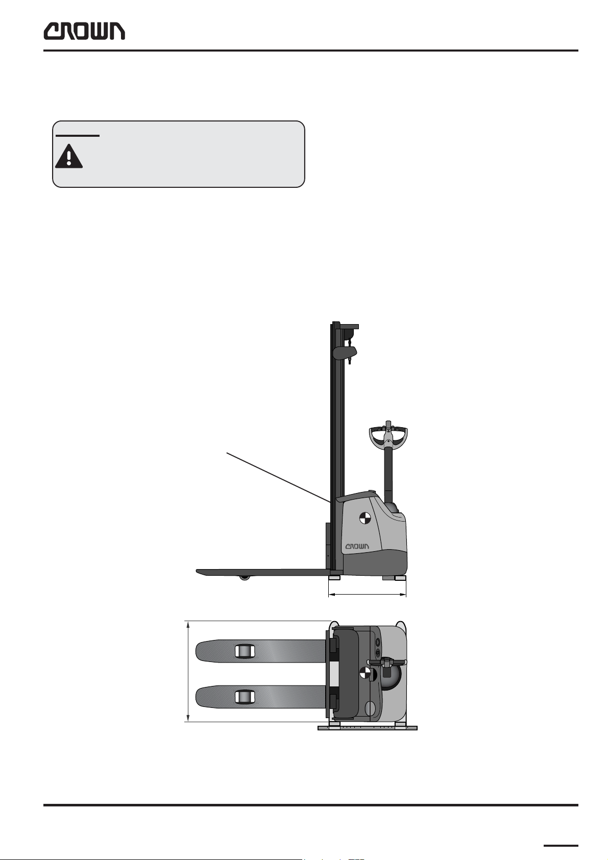
Raising With Another Forklift Truck
DANGER
Failure to read the instructions can
cause the truck to tip over or fall from the
forks. Fatal accidents could result.
● Position the forks of the truck which is doing the
lifting as shown by the diagram below.
● The centre of gravity of the WF 3000 with and
without the battery is near the battery compartment. It should always be between the forks of
the truck doing the lifting.
● Secure the WF 3000 firmly to the forks of the
truck which is doing the lifting (e.g. with appropriate straps).
Schwerpunkt
> 850
> 650
MO-3300-014
WF3000 09/2005 • Printed in Germany MS-1.0-3300
11
Page 26
LUBRICATION AND ADJUSTMENT
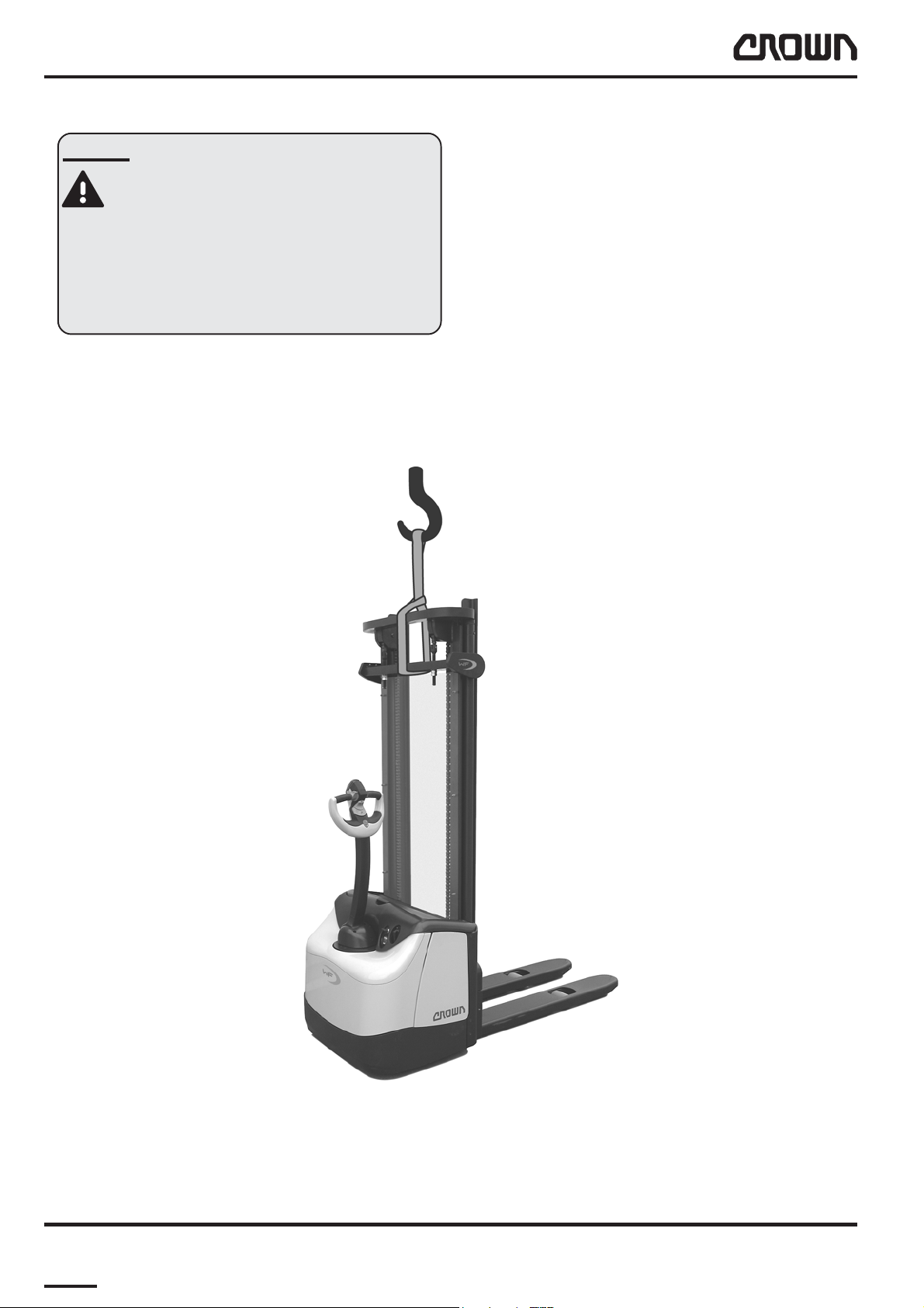
Lifting by Crane
DANGER
Make sure the crane / fork lift and the
lifting equipment have sufficient capacity.
If the crane / lift truck crash or a load
falls, fatal injuries can result.
Capacity required: 900 kg
Attach lifting gear as shown in the following diagram and
prevent the truck from slipping.
12
MO-3300-013
WF3000 09/2005 • Printed in GermanyMS-1.0-3300
Page 27
LUBRICATION AND ADJUSTMENT
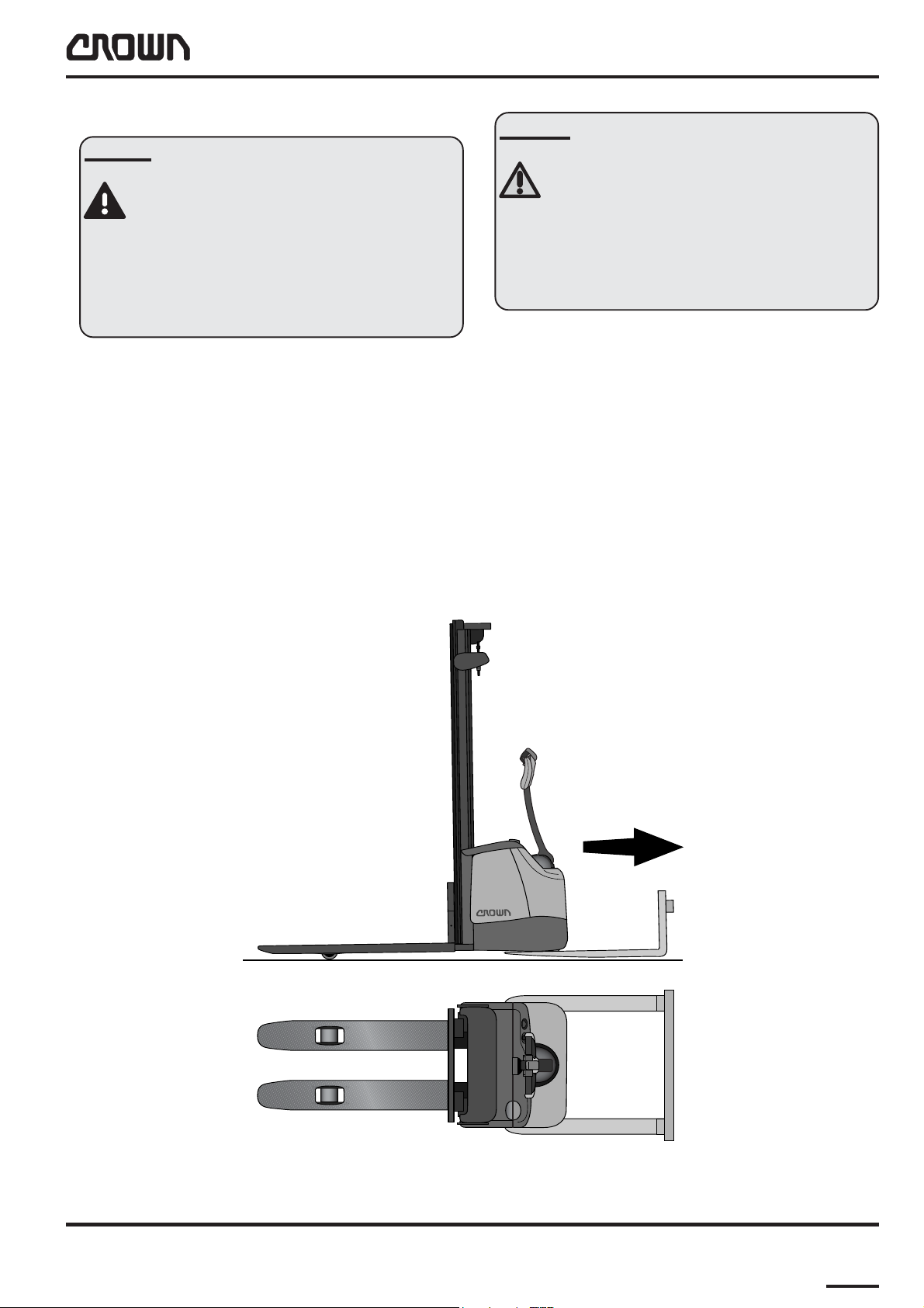
Towing the Truck
DANGER
Tipovers can result in fatal accidents.
If the towing truck negotiates a bend, a
fork will slip under the truck that is being
towed. This can cause the towed truck to
tip over and result in fatal injuries.
Only travel straight ahead when towing.
When the truck is de-energised, the brake (acting on the
drive wheel) is applied. To remove the truck from an aisle,
for example , it can be raised and pulled by a f orklift truck.
The required capacity (WF unladen, with battery , 800 kg):
1100 kg. The load wheels remain on the ground when
the truck is towed.
CAUTION
Risk of damage to the drive system.
If the drive wheel is still touching the
ground, the drive system will be damaged when the truck is towed.
Only raise the truck so far that the drive
wheel is not touching the ground.
● Position the forks as shown in the diagram.
● Raise the truck (at its front) approx. 20 mm, but
no higher than necessary as otherwise the
bottom of the WF’s fork tips will scratch the
ground.
MO-3300-015
WF3000 09/2005 • Printed in Germany MS-1.0-3300
13
Page 28
LUBRICATION AND ADJUSTMENT
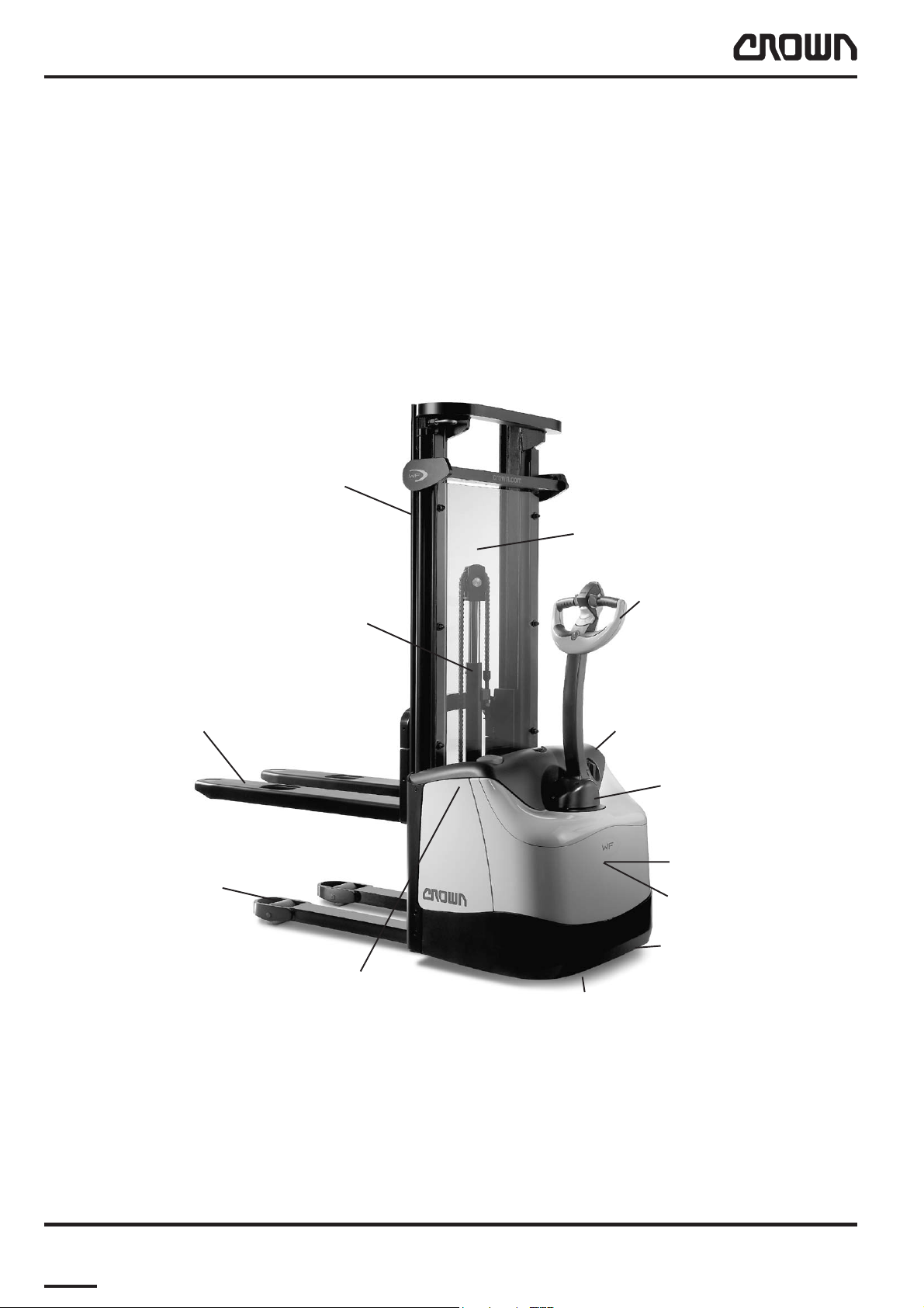
Component Access
Undo the 3 screws securing the dashboard. Lift off the
dashboard and panel to gain access to the components
beneath the panel.
Note: The illustration shows the model with the TT mast.
Mast
Fork
Load wheel
Safety Screen
Control handle
Free lift cylinder
Dashboard
Control handle knuckle
Controller and contactors
Traction and pump motors
Caster wheel
14
Battery and battery connector
Drive wheel
WF3000 09/2005 • Printed in GermanyMS-1.0-3300
Page 29

LUBRICATION AND ADJUSTMENT
After disassembling the top panel you will be able to
access the:
● Diagnostic LED on the TCM
● Fuse FU1 (travel power fuse)
● Fuse FUS (raise power fuse)
● Combination instrument
● Fuse FU3 (signal)
● Fuse FU4 (cold store versions only)
After lifting off the bottom panel you will be able to
access the:
● Traction motor
● Power unit
● Brake
● Pump motor
The control handle knuckle contains the:
● BRS (brake switch)
● ORS (brake override zone switch)
The mast contains the:
● FLS (flashing light)
● LMS (lift limit switch)
● Hydraulic unit
● Horn
● Alarm transmitter
● Diode block
● Main contactor
● Relay K2
● Alarm filter block
● TCM (traction control module)
● HCM (hydraulic control module)
The hand grip contains:
● HNS1 & HNS2 (horn switches)
● LOS1 & LOS2 (fork lower switches)
● RAS (raise switch)
● HSS (fast / slow travel switch)
● SAS (safety reverse switch)
● FS, RS, POT (travel switch unit and
potentiometer)
WF3000 09/2005 • Printed in Germany MS-1.0-3300
15
Page 30

LUBRICATION AND ADJUSTMENT
Maintenance
Recommended Lubricants and Oils
Lubricants
The next page shows typical lubricants used by Crown
itself in its factories. Howe ver , you can use any lubricants
provided they meet the same technical criteria.
Cold Store Trucks
Special hydraulic oil, lubrication oil and grease must be
used for cold store trucks operating in low temperature
conditions (see table on following page). An anticorrosion
fluid (Crown no. 805236-004) must be applied to all
screws, washers, nuts, pins, retaining rings etc. Carefully protect all electrical connections and components
against corrosion. F or detailed information, refer to chapter 4.
Service intervals must be adapted to the conditions of
use. This means they must be reduced as far as possible to prevent excessive wear.
Taking the truck out of service
● Every 3 months connect the battery, carry out a
daily inspection and activate all the truck functions. Now disconnect the battery again.
Bringing the truck back into service
● If you wish to bring the truck back into service,
proceed as follows:
● Remove any anti-corrosion agents which have
been additionally applied (apart from the cold
store agents)*.
● Jack up the truck, remove the wooden blocks and
lower the truck.
● Charge the battery or fit a charged battery.
● Connect the battery.
● Carry out the daily inspection.
* Do not apply high pressure cleaning agents and/or
solvents to the truck. Do not use metallic brushes. Do not
wet clean the electrical system and do not use flammable solvents.
If you wish to take the truck out of service for more than
3 months, proceed as follows:
● Disconnect the battery from the truck.
● Decommission the battery in accordance with the
manufacturer’s instructions.
● Clean the truck*). Lubricate in accordance with
the maintenance manual.
● If the truck is to be stored in harsh conditions
(e.g. saline atmosphere) treat the surface of the
truck with a suitable preservative to prevent
corrosion.
● Do not park the truck in the open air or in a
humid environment. The ideal place is a dry room
where the temperature and air humidity are as
constant as possible. If the truck has to be
covered, use an air-permeable material. Do not
use plastic sheets. Otherwise, condensation may
form.
● Jack up the truck. Lower the chassis onto suit-
able wooden blocks so that the wheels clear the
ground (prevents the wheels from flattening from
constant pressure).
16
WF3000 09/2005 • Printed in GermanyMS-1.0-3300
Rev. 01/03
Page 31

Lubricant T able
LUBRICATION AND ADJUSTMENT
epyTtnacirbuL noitpircseDtcudorP
)esoprupitlum(esaerG
woL esaergerutarepmet 2LKSebularA
liociluardyH
erutarepmetwoL liociluardyh23IVHleOztueDrenkcolK900-100350DD
-unaM
rerutcaf
2PLHebularA
esaerG-ML
2AsulugeR
2PEnocaeB
2PE
2PEexuliboM
XLxaniteR
IMWGL
PEpmetoLxerinU
23FGmatiV
23-SWAnipsyH
23HotuN
42ETD
23sulleT
23ZLnardyH
011B
larA
lortsaC
yrutneC
ossE
loxaM
liboM
llehS
FKS
larA
liboM
larA
lortsaC
ossE
liboM
llehS
loniF
shcuF
ekrewlölareniM
HbmG
100-200350B
500-200350BB
300-100350D
.oNtraPnworC epyT
09W58pyH
lionoissimsnarT
erutarepmetwoL noissimsnart
lio
lionoitacirbuL
erutarepmetwoL lionoitacirbul626CHSliboM800-200350GG
gnisserdlynivdnarebbuR---------H
09W58D-XG
09/58DHebuliboM
09BMxaripS
426CHSliboMliboM900-200350AA
04lawoK
04+XDHebulossE
0421cavleD
larA
ossE
liboM
llehS
larA
ossE
liboM
400-200350A
700-200350G
L01_Lubricants_WF-GB
WF3000 09/2005 • Printed in Germany MS-1.0-3300
17
Page 32

LUBRICATION AND ADJUSTMENT
Adjuvants T ab le
tnavujdA noitpircseDtcudorP noitacilppA .oNtraPnworC
tnegaevisorroc-itnAlytceT
tniaplaesraelCkcalralKK2
dnuopmocgnitnioJokriDgnirlE
roftnegaevisorroc-itnA
.skcurterotsdloc
laesraelctnatsiser-dicA
noitcartroftniap
dlocnidesusrellortnoc
.serots
rofdnuopmocgnitnioJ
diuqil(srevoctinuraeg
.)laes
-----------------
-----------------
:egdirtraclm013
200-632508
:ebutg001
100-632508
L01_Adjuvants_WF_GB
18
WF3000 09/2005 • Printed in GermanyMS-1.0-3300
Page 33

metI noitcA
LUBRICATION AND ADJUSTMENT
)erotSdloC=C,dradnatS=X(eludehcSecnanetniaMdnatseT
stnacirbuL=...,M,A/noitacirbuL=L,noitcepsnI=I sruoHecivreS/shtnoM
3
6
001
21
42
052
005
0001
1-I
2-I
3-I
4-I
1-L
2-L
5-I.gnittesevlavfeilerkcehC C/X
6-I.rotomciluardyhnoreffubrebburkcehC C/X
7-I
8-I.raewdnaegamadrofgnilpuocrotompmupkcehC C/X
9-I.stnemhcattarotomtfildnarotomnoitcartehteuqroT C/X
01-I.levelliotinuraegkcehc,tnemhcattatinuraegehteuqroT C/X
-D/D
D
-D/D
D
.raew
.thgit
raewrofkcehc
retfasruoh05rokcurtwenanostunleehwevirdehteuqroT
.yrassecenfihsinelper,levelliociluardyhkcehC C/X
liociluardyhecalpeR C/X
.)4retpahcees(raew
dnasgniraebleehwretsacdnaleehwdaolehtfoecnaraelcehtkcehC
rofleehwevirddnasleehwretsac,sleehwdaolehtfoserytehtkcehC
.shtnom21yreverosruoh005yreve,retfaerehT.ylbmessa/lavomer
erasnoitcennockcehcdna,egamadrofsesohdnasenilciluardyhkcehC
rofsrotomnoitcartdnapmupforotatummocdnasehsurbnobrackcehC
C/X
C/X
C/X
C/X
C/X
11-I.snoitcennocelbacrewopllaeuqroT C/X
21-I.sgnirpstcatnockcehcdnastcatnocrotcennocyrettabnaelC C/X
31-I
41-I
51-I.egamadrofelbacgnitcennocregrahckcehC C/X
61-I
3-LBB/B.kcollenapyrettabdnasegnihetacirbuL C/X
.selbacdnasgnirps
.noisnet-erpelbackcehC
.noisorrocrofkcehcdnaeruceserasnoitcennocdna
tcatnoc,gnisuohrotcennockcehC.stcatnocrotcennocyrettabnaelC
?tneserpfeilerniartS.thgiterasnoitcennocgulperusnE:selbactsaM
sehctiwserusnedna,noitalusniotegamadrofsenillacirtcelellakcehC
C/X
C/X
C/X
L04_WF-GB
WF3000 09/2005 • Printed in Germany MS-1.0-3300
19
Page 34

LUBRICATION AND ADJUSTMENT
)erotSdloC=C,dradnatS=X(eludehcSecnanetniaMdnatseT
stnacirbuL=...,M,A/noitacirbuL=L,noitcepsnI=I sruoHecivreS/shtnoM
metI noitcA
71-I.raewrofkcehcdnastcatnocrotcatnocpmupnaelC C/X
81-I.raewrofkcehcdnastcatnocrotcatnocniamnaelC C/X
91-I .tnemhcattarellortnocnoitcarteuqroT.golrorrerellortnocnoitcartdaeR C/X
3
001
6
21
42
052
005
0001
02-I
12-I
22-I.sgnirpseldnahlortnocehtfoecrofgnirotserehtkcehC C/X
32-I.noisnetniahcgnireetsehtkcehC C/X
42-I.kcurtehtfotnemngilasixalaretalehtkcehC C/X
52-I .)tsetbmulpgnirewol(kcurtehtottsamehtfotnemngilaehtkcehC C/X
62-I.kcalsrofsrellorkcehcdna,skcarcrofegairrackrofkcehC C/X
72-I.egairrackrofdnaskrofneewtebkcalskcehC C/X
82-I.raewdnaegamadrofskrofkcehC C/X
92-I.raewrofkcehcdnasecafrustcatnoctsamnaelC C/X
40-LBB/B.secafrustcatnoctsametacirbuL C/X
03-I .)noitagnole(raewdnanoisorroc,egamadrofkcehc,sniahctfilllanaelC C/X
50-LGG/G.sniahctfiletacirbuL C/X
13-I.skcarcdnanoisorroc,egamadrofsrohcnaniahckcehC C/X
23-I.kcalsdnaraewrofsrellortsamkcehC C/X
60-LBB/B.srelloregairrackrofdnasrellortsametacirbuL C/X
.pagriakcehC.egamad
.stnenopmocdegamadronrowynaecalpeR.egamad
rofelppinlacinocehtkcehC.ekarbninoisarbaotriadesirusserpylppA
dnaraewrofkcehcdnastnenopmocllanaelC.ekarbehteltnamsiD
C/X
C/X
33-I .dettifylerucessitierusnednaegamadroftserkcabdaolkcehC C/X
WF3000 09/2005 • Printed in GermanyMS-1.0-3300
20
L05_WF-GB
Page 35

metI noitcA
LUBRICATION AND ADJUSTMENT
)erotSdloC=C,dradnatS=X(eludehcSecnanetniaMdnatseT
stnacirbuL=...,M,A/noitacirbuL=L,noitcepsnI=I sruoHecivreS/shtnoM
3
6
001
21
42
052
005
0001
43-I
70-LH .srelloresohetacirbuL C/X
80-LGG/G.syellupniahcetacirbuL C/X
90-LAA/A.yrassecenfihsinelper,levellioraegkcehC C/X
01-LAA/AlioraegecalpeR C/X
53-I
-
-)4retpahcees,tsetytefasrellortnocnoitcart(tsetTMP yllaunnax1
.kcalsdnaegamad
.sesuftnemhcattarednilyckcehC.delaes
.)snoitalugerlanoitan
,raewrofgninoihsuctimiltsamdnasrelloresoh,ekoyyellup,syellupkcehC
sirednilycerusnednaegamadrofsdornotsiprednilycciluardyhkcehC
otrefer,seirtnuocrehtoroF.ylnoynamreG(.noitcepsniVVUehttuoyrraC
C/X
C/X
L06_WF-GB
yllaunnax1
WF3000 09/2005 • Printed in Germany MS-1.0-3300
21
Page 36

LUBRICATION AND ADJUSTMENT
T ruck Tilt Settings
DANGER
Truck tipovers can result in fatal injuries.
The risk of a tipover is greatly increased
by setting the truck tilt angle beyond the
tolerance level.
Adjust the truck tilt angle regularly and
with care.
The stability of the truck requires the tilt
angle to be kept as low as possible.
Maximum stability is achieved by measuring the lateral
inclination and carrying out a lowering plumb test on the
mast with appropriate adjustment.
The inclination of the truck and therefore the mast
changes as the drive wheel and / or the caster wheel
increasingly wear.
● Fix the caster wheel again. Repeat the measurement to check the adjustment.
● If necessary, repeat the adjustment until the
difference in height on the two sides is within the
tolerance lev el.
● Now carry out the lowering plumb test.
Lowering Plumb Test
Test the lateral inclination before carrying out the
lowering plumb test.
The truck must be parked on a flat, level surface. The
max. permissible deviation from the evenness and
levelness of the 4 contact points on the truck (the
two load wheels, caster wheel and drive wheel) must
be less than 1 mm.
● Attach a test load (the maximum weight at maximum lift height and with the correct load centre of
gravity - see capacity plate).
The inclination of the truck must be checked and if necessary adjusted in the following cases:
● Lateral inclination and lowering plumb test at the
intervals given in the maintenance schedule.
● Replacing the drive wheel
● Replacing the caster wheel
● Replacing the mast
Testing and adjustment take place in 2 stages:
Testing and Adjusting the Lateral Inclination
The truck must be parked on a flat, level surface. The
max. permissible deviation from the evenness and
levelness of the 4 contact points on the truck (the
two load wheels, caster wheel and drive wheel) m ust
be less than 1 mm.
● Measure the skir t height off the ground (at the
separating joint) on the left and right hand sides.
The difference between the left and right hand
sides should not exceed +/- 1mm.
● Adjust the height of the caster wheel to correct
the lateral inclination of the chassis. To do this,
undo the locking screw (3, Fig. MP-3300-007) and
adjust the height via the setscrew (1).
● Raise the test load approx. 300 mm.
● Attach a lowering plumb to the back of the fork
carriage.
● Prepare a paper rectangle: 50 mm long and 20
mm wide. Mark out the middle of the rectangle.
● Wait until the plumb has finished oscillating and
stick the previously prepared paper rectangle
onto the ground below the plumb. The centre
should lie underneath the tip of the plumb. The
long side of the rectangle (50 mm) should be
perpendicular to the truck’s longitudinal axis.
● Now extend the mast as far as the stop and then
lower it a few millimetres. It is important that the
mast is not tensioned at the limit positions.
● Check the position of the lowering plumb. The
plumb should not now be pointing outside the
rectangle.
● If the plumb is pointing outside the rectangle in
the lateral direction, the lateral mast inclination
must be compensated using shims 813875-001/-
002. The shims are positioned between the base
of the outer mast and the truck base (RH or LH)
and screwed to the rear panel of the battery.
22
WF3000 09/2005 • Printed in GermanyMS-1.0-3300
Page 37

LUBRICATION AND ADJUSTMENT
● If the plumb is pointing outside the rectangle in
the longitudinal direction, either the drive and
caster wheels or the load rollers are heavily worn.
In this case, check the wheels and rollers for
wear and replace any worn wheels and rollers.
Now repeat the lateral inclination setting and the
vertical plumb test.
1
2
3
4
5
6
14
13
12
9
7
11
10
8
WF3000 09/2005 • Printed in Germany MS-1.0-3300
9
MP-3300-007
10
23
Page 38

Blank page
24
Printed in Germany
Page 39

Printed in Germany
HYDRAULICS
25
Page 40

Blank page
26
Printed in Germany
Page 41

Hydraulic Symbols
Vented reservoir
with lines above the fluid level
Vented reservoir
with lines below the fluid level
Filter or strainer
M
M
HYDRAULICS
Electric motor
with unidirectional turn and speed
Electric motor
with unidirectional turn
and variable speed
Hydraulic line with full flow
(tubing or hose)
Pilot or drain line or drainage
with limited flow
Lines crossing; not connected
Lines crossing and connected
Hydraulic pump
with fixed displacement
and single direction of turn
Hydraulic motor,
bi-directional
Pressure gauge
Thermometer
Plugged port (test por t )
Flow meter
M3559
WF3000 09/2005 • Printed in Germany
Accumulator gas charged
diaphragm type
MS-2.0-0000
M1.0-0000-00027M-1.0-0000-0002727
Page 42

HYDRAULICS
Pressure switch
Double-acting cylinder;
unequal area
Double-acting cylinder;
equal area
Single-acting cylinder
with spring returned
(rod end vented)
Single-acting cylinder
ram type
Manual actuator
Spring, (bias to normal deenergised position)
Solenoid single coil or winding
Hydraulic pilot operated
Single-acting cylinder,
with cushion
Assembly housing,
manifold block
Manual lever actuator
Solenoid valve, pilot operated
Dual solenoid
Proportional solenoid
Pilot check valve (pilot to open)
M3560
MS-2.0-0000
M1.0-0000-00028M-1.0-0000-0002828
WF3000 09/2005 • Printed in Germany
Page 43

HYDRAULICS
Throttle, fixed
Throttle, adjustable
Pressure-compensated
flow control, fixed
Pressure-compensated
flow control with reverse
flow bypass; fixed.
Shuttle valve
Single counterbalance valve
assembly in manifold
Flow divider/combiner
Velocity fuse
Relief valve, fixed setting
Relief valve, adjustable
Check valve
Bypass flow control
with controlled flow,
pressure-regulated
Shut-off valve, manual
P
T
T
P
L
R
Torque generator
Hydraulic steer unit
M3561
WF3000 09/2005 • Printed in Germany
MS-2.0-0000
M1.0-0000-00029M-1.0-0000-0002929
Page 44

HYDRAULICS
2/2 way valve
(two way, two switch positions)
3/2 way valve
(three way, two switch positions)
4/2 way valve
(four way, two switch positions)
Valve block with
3 operating units
4/3 way valve
(four way, two switch positions)
4/3 way valve
(four way, two switch positions);
manual activation and spring centered
3/2 way valve
(three way, two switch positions);
Spring bias solenoid control
M3562
MS-2.0-0000
M1.0-0000-00030M-1.0-0000-0003030
WF3000 09/2005 • Printed in Germany
Page 45

HYDRAULICS
Hydraulics
Hydraulic Reservoir Capacity
The hydraulic reservoir has a capacity of 5.4 litres up to
the max. oil le vel mark. The marking on the hydraulic reservoir serves to indicate the maximum capacity. When
checking the hydr aulic oil lev el, mak e sure that the cylinders are fully retracted and that the entire hydraulic system is fully bled.
Only start the truck once the reservoir has been filled
with the approved hydraulic oil up to the maximum level.
For the correct grade, ref er to the lubricant table in Chapter 1.
The hydraulic oil is filled up to the marking on the hydraulic reservoir. The oil le vel should not de viate by more
than +/-3 mm from this level.
Changing the Hydraulic oil and Hydraulic Filter
WARNING
De-pressurise all components before
carrying out maintenance work on the
hydraulic system.
High pressure hydraulic oil can cause
serious injuries.
Whenever a high pressure fluid enters
the skin it must be treated as an emergency, even if the skin initially shows no
reaction.
Physical effects may take time to set in.
Secure all connections before re-apply-
ing system pressure. Keep hands and
body away from any ports as high pressure hydraulic oil can emerge.
MS-3300-001
Use absorbent paper to trace leaks,
never use your hands!
● Fully lower the forks. Retract the mast fully.
● Turn the key switch OFF. Remove the key. Dis-
connect the battery.
● Attach a warning tag to the control handle to
advise others that the truck is being serviced.
● Chock the drive wheel and load wheels.
● Remove the front cover from the drive unit to
access the hydraulic reservoir.
● Remove the knuckle cover and the two-part
centre cover of the control handle. Rotate the
control handle 90° (towards the hydraulic reservoir). This will give you better access to the
hydraulic system components.
● Undo the retaining strap which secures the motor
to the chassis. Push the strap up to loosen it from
the chassis.
WF3000 09/2005 • Printed in Germany MS-2.1-3300
31
Page 46

HYDRAULICS
● Separate the hydraulic lines from the hydraulic
pump. Seal the hydraulic ports immediately to
minimize oil loss and prevent hydraulic system
contamination.
● Disconnect all electrical wiring from the hydraulic
unit. Insulate the wire ends to prevent sparking.
Tag out the wire ends and motor ter minals to
avoid any confusion when you later connect the
wires.
● The reservoir and motor/pump assembly can now
be moved. Carefully raise the reservoir and pull it
forward as far as possible. Remove the reservoir
and the motor/pump assembly from the drive unit
frame.
● Remove the screw from the clamp securing the
motor/pump assembly to the reservoir flange.
Open the clamp until it drops off the flange and
rests on the top of the reservoir.
● Lift the motor/pump assembly from the reservoir.
● Remove the oil from the reservoir and any re-
mains that have built up in the reservoir. Observe
local disposal regulations.
● Fill the reservoir up to the full mark via a filter (at
least 10 micron) using the correct hydraulic oil
grade according to the operating conditions of the
truck (see Chapter 1, Lubricant table).
● Refit the covers of the control handle, and tighten
the mounting screws firmly.
● Refit the front cover of the drive unit, and tighten
the mounting screws firmly.
● Remove the wedge.
● Connect the battery and remove the warning tag
from the control handle.
● Bleed the hydraulic system (see Chapter 8,
Cylinder Bleeding and Flushing).
● Remove the retaining ring of the strainer in the
filter housing of the suction line below the pump.
Replace the filter. Refit the strainer in the filter
housing of the suction line. Attach the strainer
and the retaining ring.
● Fit the motor/pump assembly onto the reservoir.
Centre the pump flange with the flange on the
reservoir.
● Refit the clamp and tighten the mounting screw
firmly.
● Fit the reservoir and the motor/pump assembly in
the drive unit frame.
● Connect the power cables to the pump motor and
tighten the connections securely.
● Reconnect the hydraulic supply lines and the
electrical connections. Tighten the connections
firmly.
● Make sure that the reservoir and motor/pump
assembly are against the frame. Now tighten the
holding strap to secure the motor/pump assembly
to the drive unit frame.
32
WF3000 09/2005 • Printed in GermanyMS-2.1-3300
Page 47

HYDRAULICS
Hydraulic system
Function
Lifting (see diagram)
If the “Raise” switch is pressed down on the control handle, the pump motor is energised and starts to drive the
pump. The pump initially draws oil from the reservoir via
the suction filter, directing it through the internal check
valve and the proportional valve which opens briefly, and
back to the oil reservoir. While the propor tional valve is
fully closed, the operating pressure builds up on the lift
cylinder (soft lift). A relief valve in the circuit keeps the
pressure to the maximum permissible limit.
1 Suction filter
2 Reservoir ventilation
3 Check valve (CV)
4 Overload valve (RV)
5 Cylinder shutoff valve (SVCL)
6 Proportional valve (PV)
7 Pump & motor
8 Line break safety device (LH lift cylinder, opposite
the fork direction)
9 Free lift cylinder line break safety device
10 Reservoir
11 Flow restrictor
12 Line break safety device (RH lift cylinder, opposite
the fork direction)
12
A
Suction line
Pressure line
NT mast
Lift - Hydraulics
TL mast
Lift - Hydraulics
8
A
12
SVCL
M
9
5 3
CV
TF mast
Lift - Hydraulics
8
A
6
PV
11
4
RV
230 bar
A
2
8
WF3000 09/2005 • Printed in Germany MS-2.1-3300
7 1 10
M3435a
33
Page 48

HYDRAULICS
Lowering (see diagram)
If one of the two “Lower” switches (LOS1 or LOS2) is
pressed down on the control handle, the shutoff valve
opens. At the same time the proportional valve opens
according to whether LOS1 or LOS2 has switched fully
or partially. The hydraulic oil can now flow from the
cylinder(s) via the flow restrictor back to the oil reservoir.
If the proportional valve is partially open, lowering is slow.
If the proportional valve is fully open, lowering is fast.
TL mast
Lift - Hydraulics
1 Suction filter
2 Reservoir ventilation
3 Check valve (CV)
4 Overload valve (RV)
5 Cylinder shutoff valve (SVCL)
6 Proportional valve (PV)
7 Pump & motor
8 Line break safety device (LH lift cylinder, opposite
the fork direction)
9 Free lift cylinder line break safety device
10 Reservoir
11 Flow restrictor
12 Line break safety device (RH lift cylinder, opposite
the fork direction)
12
TF mast
Lift - Hydraulics
A
Return
NT mast
Lift - Hydraulics
A
9
12
8
A
8
5 3 6
A
PV
SVCL
CV
RV
M
SX: 205 bar
ST: 175 bar
8
11
4
2
34
7 1 10
M3565a
WF3000 09/2005 • Printed in GermanyMS-2.1-3300
Page 49

HYDRAULICS
MOTOR AND PUMP ASSEMBLY
Hydraulic Lines and Fittings
WARNING
De-pressurise all components before
carrying out maintenance work on the
hydraulic system. High pressure hydraulic oil can cause serious injuries.
Whenever a high pressure fluid enters
the skin it must be treated as an emergency, even if the skin initially shows no
reaction.
Physical effects may take time to set in.
Secure all connections before re-apply-
ing system pressure. Keep hands and
body away from any ports as high pressure hydraulic oil can emerge.
Use absorbent paper to trace leaks,
never use your hands!
General Rules for Hydraulic Lines and Connections
● Apply pressurised air to all hoses and lines
before assembling them, to remove any loose
particles. Bent steel or plastic lines will be permanently damaged. These must be replaced even if
the damage is not externally visible.
● Any hose which bends during operation in its
normal assembly position must also be replaced.
Drift Test
Whenever work has been performed on hydraulic components a drift test must be carried out to ensure that
certain system components are working correctly. The
procedure for doing this can be f ound in Chapter 8 under
“Drift T est”.
Proportional function:
Whenever maintenance work has been perf ormed on the
hydraulic system.
Ensure that the load can start smoothly when the lift motor
is switched on and that the load can also brake smoothly
when lowering is switched off (subjective test).
The HCM (hydraulic control module) ma y have to be calibrated (see Electrics chapter).
REMOVAL
WARNING
De-pressurise all components before
carrying out maintenance work on the
hydraulic system.
High pressure hydraulic oil can cause
serious injuries.
Whenever a high pressure fluid enters
the skin it must be treated as an emergency, even if the skin initially shows no
reaction.
Physical effects may take time to set in.
● All hoses and lines must have sufficient clearance from other surfaces or edges that could
result in wear or cuts or where the hoses or lines
could get caught.
● All connections must be tight and without leaks.
Bleeding the Hydraulic System
Whenever work has been performed on hydraulic components, the hydraulic system must be flushed and b led.
The procedure for doing this can be found in Chapter 8
under “Cylinder Bleeding and Flushing”.
WF3000 09/2005 • Printed in Germany MS-2.1-3300
Secure all connections before re-applying system pressure. Keep hands and
body away from any ports as high pressure hydraulic oil can emerge.
Use absorbent paper to trace leaks,
never use your hands!
● Fully lower the forks. Retract the mast fully.
● Turn the key switch OFF. Remove the key. Dis-
connect the battery.
35
Page 50

HYDRAULICS
● Attach a warning tag to the control handle to
advise others that the truck is being serviced.
● Chock the drive wheel and load wheels.
● Remove the front cover from the drive unit to
access the hydraulic components.
● Disconnect the power cables from the pump
motor. Insulate the wire ends to prevent sparking.
● Disconnect all the hydraulic supply lines and/or
electrical connections that obstruct you when
removing the motor/pump unit.
● Remove the strap (and where applicable the
spacer) which fixes the pump motor to the chassis. Undo the clamp that fixes the motor/pump
assembly to the reservoir.
● Remove the motor/pump assembly from the
reservoir and take it to a suitable work area for
further dismantling.
● Check the connections again for leaks once the
system has reached operating temperature.
MOTOR
Refer to Chapter 4, “Electrics”, for pump motor maintenance and repair instructions.
PUMP
The hydraulic pump cannot be serviced and can only be
replaced as a complete assembly. Before fitting a new
pump, make sure that the pump and all its h ydraulic components are clean. Install a new suction filter (see section on changing the hydraulic oil and filter).
After replacing the pump:
● Use clean, filtered hydraulic oil (at least 10
micron) to replenish the reservoir.
● Never run the pump without oil.
● Star t the installed pump unladen (pressure side
open) and leave it to pump hydraulic fluid for
max. 20 seconds. This will ensure the pump is
bled and that there is sufficient lubrication. Close
the pressure side again as soon as the oil
emerges without bubbles. Bleed the entire system (see Chapter 8, Cylinder Bleeding and
Flushing).
● If the oil is still foaming after approx. 20 seconds,
the system must be checked (see “Hydraulic
System Troubleshooting Table” on following
page).
36
WF3000 09/2005 • Printed in GermanyMS-2.1-3300
Page 51

Replacing the relief valve
● Remove the locking mechanism (4) and unscrew
the relief valve (3),
● Remove the O ring and the strainer from the
valve seat if they are still in there.
● Apply a thin coat of hydraulic oil to the new O ring
and place it in the valve seat with the strainer.
● Apply hydraulic oil to the relief valve, insert it into
the valve seat and tighten. Tap in the new locking
mechanism.
● Refit the hydraulic unit and adjust the relief valve.
Relief valve test and setting
The relief valve protects the hydraulic system and the
lifting mechanism from overloading.
HYDRAULICS
Repeat the test. Repeat the setting until the relief
●
valve opens within the tolerance range.
WARNING
Do not let the pump unit run unless it is
fixed to the chassis.
The amount of torque will twist the unit.
This can result in short circuits and
damage.
ledoM
0.1-0003FWt0,1gk001,1gk002,1
2.1-0003FWt2,1gk023,1gk024,1
● With the truck at operating temperature, raise a
detaR
yticapac
muminiM
daol
daol
H01_GB
test load on the forks that corresponds to 110%
of rated capacity (= minimum load). It should be
easy to raise the load.
● Now raise a test load that corresponds to 110%
of rated capacity + 100 kg (=maximum load). It
should not be possible to raise this load. (relief
valve opens).
3
2
1
MS1723-007
4
mumixaM
lIf necessary, adjust the relief v alve so that it opens within
the above mentioned tolerance range.
● Hold onto the setscrew (1) and loosen the jam
nut (2): Tur n the setscrew clockwise to increase
the limit until the valve opens, turn it anti-clockwise to reduce the limit
● Counter-fix the setscrew (1) again with the nut
(2).
WF3000 09/2005 • Printed in Germany MS-2.1-3300
Rev. 01/03
37
Page 52

HYDRAULICS
Hydraulic System Troubleshooting
motpmyS esuaCelbaborP ydemeR
pmuPysioNlevelliowoL•
liociluardyhgnimaoFmetsysniriA•
gnitaehrevolioropmuP liodradnats.g.e(ytisocsivliotcerrocnI•
wolfwoLmetsysniriA•
.hsinelper,levelliokcehC
liodradnats.g.e(ytisocsivliotcerrocnI•
)erotsdlocnidesu
pmup(kaelnoitcennocesohtelnI•
)riasnoitcus
retlifesohnoitcusdekcolbyllaitraP•
lioniretaW•
)erotsdlocnidesu
retawhtiwdetanimatnocliO•
metsysniriA•
nepoyltnenamrepevlavfeilererusserP•
evlav
woloottesrognikaelevlavfeileR•
tohootliO•
.noitacilppa
.pmup
retlifecalpeR
levelliokcehC
pmup
ecalperdnariovresernaelC
.liociluardyh
.lionaelc
levelliokcehC
)"liOgnimaoF"ees(pmup
."liognimaoF"eeS
ytluaffiecalper,evlav
ehtrofliociluardyhtcerrocehtesU
ehtotnoitcennocenilnoitcuskcehC
ehtotnoitcennocenilnoitcuskcehC
htiwllifdnanaelc,niardylluF
.noitacilppaehtroflioelbatius
ddadnariovresernaelc,niardylluF
otnoitcennocenilnoitcuskcehC
feilerfonoitarepodnagnitteskcehC
"gnitaehrevOliOropmuP"eeS
feilerfonoitarepodnagnitteskcehC
erusserpdliuboteruliaFevlavfeilerevitcefeD•
,evlavfeilerfonoitarepokcehC
levelliowoL•
lioddA
.ytluaffiecalper
H02-GB
38
WF3000 09/2005 • Printed in GermanyMS-2.1-3300
Page 53

Printed in Germany
DRIVE UNIT
39
Page 54

Blank page
40
Printed in Germany
Page 55

Gear Unit
DRIVE UNIT
Drive unit attached to flange of
control handle support
Discharge filter
Drive motor with drive pinion removed
MS-3230-100
Drive wheel
Gear unit cover
Pinion shaft and gearwheel
Oil refill plug (6 Nm)
Oil level
Driven shaft and gearwheel
M1472
Drain plug (6 Nm)
WF3000 09/2005 • Printed in Germany MS-3.1-3300
41
Page 56

DRIVE UNIT
Drive unit, general
The drive unit consists of the gear unit and the drive motor .
The drive motor can be removed without removing the
drive unit or dismantling the gear unit. For a v ertical drive
system it is not necessary to drain the oil.
WARNING
The drive unit is heavy.
Use a suitable device to prevent the drive
unit from tipping over on removal.
The easiest method is to lift the truck
away from the loosened drive unit using
a crane.
If you have to jack up the truck in order
to release the drive unit, firmly secure the
truck underneath.
Drive unit removal
● Disconnect the battery and prevent the truck from
being switched on again.
● Prevent the drive unit from tipping over and
remove the 4 mounting screws (1, Fig. MS1723-
031) which secure the drive unit to the flange of
the control handle support.
● Either jack up the truck so that the drive unit can
be removed from underneath it, or raise the truck
using a crane with sufficient capacity (see chapter 1 for instructions and safety notes).
● Position the drive unit in a secure device.
Drive motor removal
NOTE
If you are removing the drive motor with
the drive unit installed, you must ensure
that the motor does not get caught in the
bearing cage of the drive unit when it is
removed.
Tilt the drive unit so that the motor can be freely removed.
● Disconnect the battery and prevent the truck from
being switched on again.
● Disconnect the electric wiring from the motor.
● Disconnect the electric wiring from the motor.
1
● Unscrew the mounting screws (A, Fig. MS1723-
021) approx. 5 mm from out of the housing.
A
42
MS1723-031
MS1723-021
WF3000 09/2005 • Printed in GermanyMS-3.1-3300
Page 57

DRIVE UNIT
C
B
MS1723-024
Motor disassembly
NOTE
All item numbers in the following sections refer to Figure MS-1723-027-A on
MS1723-022
the following page unless another figure
number is indicated.
● Unscrew both screws (B, Fig. MS1723-022).
● Screw 2 M8 bolts into the thread (B, Fig.
MS1723-022) with a minimum length of 35 mm
and tighten them on alternate sides until the
motor is removed from the centering shoulder.
● Prevent the motor from falling out! Unscrew
both screws (A, Fig. MS1723-021). Attention:
Take care not to damage the toothing (C, Fig.
MS1723-024) and D, Fig. MS1723-023)
D
● Remove the motor as described in the previous
section.
● Disassemble the brake (see “Brake” chapter).
● Remove the retaining ring (40).
● Remove the pinion (1) via the bushing (11) using
an extractor .
● Remove the conical nipple (29).
● Press out the shaft seal (32).
● Extract the bearing (20) and the inner ring (12).
Motor assembly
● Press the bearing (20) onto the rotor shaft. At the
same time hold the opposite shaft end securely.
● Seal the inner ring (12) with Loctite® 601.
● Place the conical nipple (29) in the bushing (11)
and press in the shaft seal (32). Now insert the
ball bearing shim (33) into the bushing (11).
● Fit the complete bushing onto the motor armature.
● Inser t the feather key (50) and the pinion (1).
MS1723-023
WF3000 09/2005 • Printed in Germany MS-3.1-3300
43
Page 58

DRIVE UNIT
58
5
59
29
33
11
32
1
40
50
12
20
6
70
31
7
3
24
21
30
22
51
61
62
2
45
48/49
4
44
43
60
44
23
9
MS1723-027A
WF3000 09/2005 • Printed in GermanyMS-3.1-3300
Page 59

● Fit the retaining ring (40).
● Attach the brake (see “Brake” chapter).
● Fit the motor as described below.
Drive motor assembly
Tools required: 2 off M6 threaded rods, approx. 100
mm long.
● To aid the assembly, screw 2 off M6 threaded
rods, approx. 100 mm long, into two opposite
threaded holes of the motor (E, MS1723-023)
DRIVE UNIT
A
E
MS1723-023
● Push the motor into the gear unit with the mounting aids ahead, and push it into the locating edge.
Take care not to damage the toothing in the
process.
● Insert the two mounting screws of the motor (A,
Fig. MS1723-021) back onto the gear unit. Alternately tighten the two screws in small increments.
This will pull the motor completely into the
centering shoulder and prevent it from twisting in
the centering shoulder.
● Refit the screws (B, Fig. MS1723-022).
MS1723-021
B
● Torque screws A, Fig. MS1723-021 and B, Fig.
MS1723-022 to 10 Nm.
● Refit electrical connections to the motor and the
brake.
● Carry out an operational test.
WF3000 09/2005 • Printed in Germany MS-3.1-3300
MS1723-021
45
Page 60

DRIVE UNIT
Gear unit disassembly
General
NOTE
It is not necessary to remove the motor
is you are dismantling the gear unit and
re-assembling it.
If you are dismantling the gear unit, you
must replace all bearings and seals.
Used bearings and seals will result in
premature failure of the unit.
Preparation
● Disconnect the battery and prevent the truck from
being switched on again.
● If necessar y, remove the motor as described in
the previous section.
● Unscrew and remove the drive wheel.
Draining the oil
● Place a tray underneath the drain plug (G, Fig.
MS1723-029) of the gear unit and drain the oil.
Unscrew the control plug (F) to allow the oil to
drain faster.
Drive unit removal
● Now remove the drive unit for disassembly. Refer
to the “Drive unit removal” section at the start
of this chapter.
● Remove both screws (58, Fig. MS1723-027) and
the 10 screws (6) which secure the housing lid.
Gear unit cover removal
WARNING
Do not damage the contact surfaces of
the gear unit housing and the gear unit
cover.
Do not use a thick tool (screwdriver or
similar). This will damage the contact
surfaces.
● Tap a burr-free, thin tool along the circumference
of the seal gap until the housing cover can be
gently removed (see Fig. MS1723-030).
F
G
MS1723-029
● Using a scraper carefully remove the sealant
remains from the contact surfaces of the gear
unit housing and the gear unit cover. Now thoroughly clean the contact surfaces with a suitable
solvent (e.g. Loctite® 7063 Cleaner).
46
MS1723-028
WF3000 09/2005 • Printed in GermanyMS-3.1-3300
Page 61

DRIVE UNIT
Gear unit disassembly
NOTE
All item numbers in the following sections refer to Figure MS-1723-0027-A on
the following page unless another figure
number is indicated.
● Remove the retaining ring (61, Fig. MS1723027A) and the supporting ring (62).
● Using a suitable extractor pull off the wheel (2).
● Remove the retaining ring (45) and the two shims
(48, 49).
● Press off the driven shaft (7) in the direction of
the drive wheel. This will inevitably damage the
bearing (23).
● Remove the retaining ring (44) and extract the
bearing (23). The bearing can no longer be
used.
● Remove the retaining ring (43) and extract the
bearing (24) via the outer ring.
● Press the shaft seal (31) from the outside into the
seat on the gear unit housing.
● Fit the outer ring of the roller bearing (24) and
insert the retaining ring (43).
● Place the bushing (9) onto the rollers of the
bearing (24) and press the bearing (23) into the
gear unit housing and insert the retaining ring
(44).
● Place the wheel (4) in position and guide the
drive shaft carefully into the shaft seal. Align the
bushing in the process.
● Align the wheel (4) with the tooth shaft profile of
the drive shaft (7).
● Suppor t the wheel (4) with suitable bushing and
press the drive shaft (7) into the wheel (4).
● Using an appropriate number of shims (49),
distance the drive shaft (7) between the two
shims (48) so that there is no slack and insert the
retaining ring (45).
● Press the bearing (22) onto the pinion shaft (3).
● Now press out the shaft seal (31).
● Remove the retaining ring (42) and the sealing
cover (30).
● Press off the pinion shaft (3) in the direction of
the gear unit cover (6). Both bearings (21 and 22)
will remain on the pinion shaft.
● Remove the two bearings (21 and 22) from the
pinion shaft (3).
NOTE
The output gear is part of the motor. The
procedure for removing the pinion and
the bearings is described in the Drive
Motor section on the previous pages.
Gear unit assembly
Replace all bearings and seals. Used bearings and
seals will result in premature failure of the unit.
● Hold against the inner ring of the bearing (21)
and fit the pinion shaft (3). Press in the retaining
ring (42).
● The contact surfaces of the cover and gear unit
housing must be clean and oil-free. If necessary,
clean the surfaces as described in the Gear Unit
Cover Removal section.
● Apply a layer of Dirko® sealant (part no. see
chapter one, lubricants) all around the contact
surfaces of the gear unit cover.
● Inser t the feather key (51) into the pinion shaft
(3).
● Hold against the inner ring of the bearing (21)
and fit the wheel (2) onto the pinion shaft (3).
● Thread the suppor ting r ing (62) onto the pinion
shaft (3) and insert the retaining ring (61).
● Press the sealing cover (30) into the housing.
● Press the bearing (21) into the housing via the
outer ring.
● Press the inner ring of the roller bearing (24) onto
the drive shaft (7).
WF3000 09/2005 • Printed in Germany MS-3.1-3300
47
Page 62

DRIVE UNIT
58
5
59
29
33
11
32
1
40
50
12
20
6
70
31
7
30
3
24
21
22
51
61
62
2
45
48/49
4
48
43
60
44
23
9
MS1723-027A
WF3000 09/2005 • Printed in GermanyMS-3.1-3300
Page 63

DRIVE UNIT
Gear unit cover installation
● Place the gear unit cover onto the housing and
press on it gently.
● Insert all 10 mounting screws (M8x16 Tuflock A)
of the cover and torque them evenly and crosswise to 25 Nm.
● If you have removed the motor, install it again as
described in the Drive Motor Assembly section.
Adding Oil
You will require approx. 0.7 litres of gear oil (see Lubricant table in chapter 1 to select an oil appropriate to your
operating conditions).
● Unscrew the discharge filter (A, Fig. MS1723-
026) and remove the control screw (B). New gear
units are fitted with a filler plug instead of a
discharge filter. This prevents from escaping
during transport. Ensure that a discharge filter is
fitted (A, Fig. MS1723-026) if the gear unit is
being installed in a truck.
● With the drive unit vertical, fill the specified
amount of gear oil up to the bottom edge of the
control screw (B) through the hole for the discharge filter (A).
● Screw the discharge filter (A) and the control
screw (B) back on once you have reached the
correct oil level. The tightening torque for the filter
and the control screw is 6 Nm.
Drive unit installation
● Install the drive unit in the reverse order of
disassembly (see Drive Unit Removal section in
the present chapter).
● Carry out an operational test of the truck and
then check the gear unit for leaks.
A
B
MS1723-026
WF3000 09/2005 • Printed in Germany MS-3.1-3300
49
Page 64

Blank page
50
Printed in Germany
Page 65

Printed in Germany
ELECTRICS
51
Page 66

Blank page
52
Printed in Germany
Page 67

Electrics - General
Wire Colour Codes
The wires used in the truck are colour-coded and numbered according to their function. The first digit or the
first two digits indicate the wire colour while the last two
digits are counter numbers.
Exceptions to this can be component leads supplied by
vendors. Each wire is identified by a number on a wiring
pictorial (refer to section DIA).
NOITAIVERBBA RUOLOC REBMUN NOITCNUF
KLB kcalB **0 langislatigiD
ELECTRICS
NRB nworB **1 langisgolanA
DER deR **2 detcennoctonevitisoP
GRO egnarO **3 retrevnocCDV21+
LEY wolleY **4 retrevnocCDdrihT
NRG neerG **5 detcennoctonevitageN
ULB eulB **6 evitagendetalusnI
OIV teloiV **7 retrevnocCDV5+
YERG yerG **8 retrevnocCDhtruoF
THW etihW **9 suoiraV
THW/DER etihW/deR **92 detcennocevitisoP
THW/NRG etihW/neerG **95 detcennocevitageN
99ot10srebmuN**
WF3000 09/2005 • Printed in Germany MS-4.0-0000
M1.0-0000-0005353
E01-GB
Page 68

ELECTRICS
Abbreviations
*tsiLnoitaiverbbAlobmyShctiwS
noitaiverbbA tnenopmoC noitaiverbbA tnenopmoC
*K yaleR SML hctiwstimiL
SCAhctiwsladeprotareleccA
SXAhctiwsnoitcnufyrailixuASROhctiwsedirrevO
SRBhctiwsekarBTOPretemoitnetoP
SIDhctiwslortnocnoitceriDARretemoitnetopesiaR
SRDhctiwsrooDSARhctiwsesiaR
SDEhctiwStcennocsiDycnegremEAERretemoitnetophcaeR
MEeludomredocnESRhctiwsesreveR
CNEredocnESAShctiwsytefasesreveR
SFhctiwsdrawroFSDShctiwstratS
SOL hctiwsrewoL
SBHhctiwsekarbdnaHSEShctiwstaeS
SSHhctiwslevarTwolS/tsaFSSShctiwsretfihsediS
SNHhctiwsnroHSHThctiwsomrehT
SYKhctiwsyeKTLThctiwstliT
SGLhctiwsthgiLSAWhctiwsgnolaklaW
.cte2VS,1VS.g.e,desueblliw
M1.0-0000-0005454
noisnetxerebmuna,ecnonahteromdesusisnoitaiverbbaevobaehtfoenofI*
WF3000 09/2005 • Printed in GermanyMS-4.0-0000
E02-gb
Page 69

*snoitaiverbbAyrdnuS
noitaiverbbA noitpircseD noitaiverbbA noitpircseD
)KA(VB yekretfaegatloVyrettaB )MP(2M rotompmuP
IDB rotacidniegrahcsidyrettaB CRM rellortnoC
ELECTRICS
RBekarB
IWBrotacidniraewhsurBProtcatnocpmuP
ACnoitcennocelbaCCP)CJgnittif(rotcennocgulP
FsliocdleifnoitcennoCBCPdraobtiucricdetnirP
NAFnaFFSdleiftnuhS
UFesuFITSrotacidnileehwgnireetS
NHnroHVSevlavdioneloS
DFIyalpsidnoitamrofnIBTdraoblanimreT
CJ)CPgnittif(rotcennockcaJMMTeludomtnemeganamkcurT
DGHO yalpsiddraugdaehrevO
ENILrotcatnoceniLTTretemruoH
)MT(1MrotomnoitcarTNMV)rotomegatlovevitageN(reppohC
noisnetxerebmuna,ecnonahteromdesusisnoitaiverbbaevobaehtfoenofI*
.cte2VS,1VS.g.e,desueblliw
WF3000 09/2005 • Printed in Germany MS-4.0-0000
M1.0-0000-0005555
E03-gb
Page 70

ELECTRICS
*snoitaiverbbarehtO
noitaiverbbA noitangiseD noitaiverbbA noitangiseD
RSCG thgirhctiwsdesolcetaG LSCG tfelhctiwsdesolcetaG
SLPhctiwsmroftalP
SPhctiwserusserPRHretaeH
MCHeludomlortnocciluardyHMLAmralalevarT
REVIECERrevieceR
IDBtnemurtsniibmoCREGRAHCregrahcdetargetnI
KRBekarbcitengamortcelERDrevirD
SLStfelhctiwstfihsediSSRSthgirhctiwstfihsediS
SCEhctiwSlortnoCnoitavelE
.cte,2VS,1VS.g.e,desueblliw
MCT rotomnoitcarT
-SNART
RETTIM
rettimsnarT
noisnetxerebmuna,ecnonahteromdesusisnoitaiverbbaevobaehtfoenofI*
E12-S1-GB
WF3000 09/2005 • Printed in GermanyMS-4.0-0000
M1.0-0000-0005656
Page 71

Electrical Symbols
ELECTRICS
EUROPE USA
123456
123456
c
NO
DESCRIPTION
Wires joining
Wires crossing
Wire connection
Plug / socket
Wire strap
Terminal board
Fuse
Assembled unit
Contact, normally open
Contact, normally closed
Contact double throw
Operating device
Operating devices,
slow releasing
Operating device,
slow operating
Hand operated
push button
Mechanically actuated
EUROPE USA DESCRIPTION
Hand operated
maintained contact
Solenoid valve
Inductor
Resistor
Capacitor
Potentiometer
U
J
Varistor
Thermal protector
T
Lamp
Horn
Battery
Diode
Breakdown diode
LED
Transistor
MOSFET
.
c
c
Hydraulically actuated
Emergency disconnect
Thyristor
Comparator
Motor armature
.
M0056-gb
WF3000 09/2005 • Printed in Germany MS-4.0-0000
M1.0-0000-0005757
Page 72

ELECTRICS
Electrical Components
DANGER
Jack up the truck before carrying out
repair work or troubleshooting the electrical system.
Traction Pod (POT, FS, RS)
The travel switches are activated via the thumbswitches
on the control handle. The traction pod comprises a s witch
(FS) for forward travel, a switch (RS) for reverse travel,
and a potentiometer (POT) which governs the travel
speed. For cold store versions the potentiometer is
heated.
Fast / Slow Travel Switch (HSS)
The fast / slow travel switch (HSS) is activated via a rotary switch (rabbit / turtle symbol) on the control handle.
The switch signal to the traction controller is used to
change between the high and slow speed ranges.
The switch is connected in series to the limit switch (LMS).
Safety Reverse Switch (SAS)
The safety rev erse switch (SAS) is activated via the s witch
cap at the top of the control handle: the traction controller immediately changes from forward to reverse travel
when the SAS is activated. The signal for normal travel
to the traction controller is simultaneously interrupted.
Depending on the traction controller setting the truck either travels for a given time, or provided the switch is
pressed, travels in reverse.
Brake Switch (BRS)
The brake switch (BRS) is immediately belo w the control
handle knuckle. As soon as the control handle reaches
the upper or lower braking zone (see Fig. M1476) the
brake switch is activ ated. The traction controller interrupts
the power supply to the traction motor (TM) and the brak e
(BR). The brake magnet releases the anchor disk which
in turn, spring powered, brakes the truck.
Override Switch (ORS)
The override switch (ORS) is immediately belo w the control handle knuckle. As soon as the control handle enters
the brake override zone (see Fig. M1476) the override
switch (ORS) sends a signal to the traction controller with
the resulting slow travel option (by pressing the traction
pod). This provides better shunt operation in restricted
conditions.
Neutral / rest position
Reverse
Upper brake zone
Brake override
Drive
Lower brake
zone
Forward
M1476
WF3000 09/2005 • Printed in GermanyMS-4.1-3300
M1.0-0000-0005858
Page 73

ELECTRICS
Raise / Lower Switches (RAS, LOS)
The raise (RAS) and lower (LOS1, LOS2) switches are
activated via rocker switches in the control handle. The
rocker switches act on switches assembled on the hydraulic circuit board of the control handle. The switches
are electrically locked in pairs so that they cannot both
be pressed at the same time.
The raise (RAS) switch activ ates the pump contactor (P)
which is controlled by the hydraulic control module (HCM):
The pump starts.
The lower (LOS) switch applies voltage to the solenoid
(SV) via the hydraulic control module (HCM). The solenoid opens.
Limit Switch (LMS)
On reaching a preset height, approx. 0.5m + the free lift
range, the limit switch (LMS) interrupts a signal to the
traction controller. The switch signal to the traction controller is used to change between the high and slow speed
ranges. The switch is connected in series to the Fast/
Slow Travel (HSS) switch.
Thermal Switch (THS)
This switch is an electronic thermostat for cold store
trucks. It is located on the main circuit board of the control handle and switches the heaters on when the temperature falls below 0°C.
Thermal switch (THS2)
This thermal switch is located in the pump motor. When
the pump motor temperature reaches 170°C, it disconnects the pump.
After cooling down to 140 °C +/- 15 °C it switches the
pump back on.
Hydraulic Control Module (HCM)
Controls the lift contactor P and the valves SVCL & PV
as a function of the raise/lower switches RAS /LOS1/
LOS2. A curve is internally stored.
Warning: Make sure you order the correct spare part to
avoid damaging system components.
Horn Switch (HNS)
A buzzer sounds when the horn button is pressed.
Key Switch (KYS)
The key switch directs the battery supply to the traction
controller and the battery discharge indicator (BDI).
Emergency Disconnect (BD)
Pulling the battery connector on the red knob at the top
of the truck completely disconnects the power supply to
the truck.
Fuses (FU)
The entire truck circuit is protected by fuses FU1 & FU2,
the control circuit by fuse FU3. Cold store trucks
have a fuse FU4 for control handle heating.
● FU1 for the traction circuit and the control lines.
● FU2 for the pump circuit.
● FU3 control circuit and options.
Unigage (BDI)
Contains an adjustable battery discharge indicator with
a specific algorithm, an hourmeter and a lift cutout system.
For a detailed description of its operation and adjustment,
refer to the appropriate chapter. Standard with some
models, otherwise optional.
Integrated Charger
Intelligent charger which disconnects the truck’s control
circuit when connected to the mains. (See electrical diagrams)
Plug Holder (PC)
To accommodate the mains plug while the truck is in
operation.
No electrical function.
Drive motor (M1)
Drive motor for the truck (separately e xcited motor), governed by the traction controller.
● FU4 heaters.
WF3000 09/2005 • Printed in Germany MS-4.1-3300
M1.0-0000-0005959
Page 74

ELECTRICS
Hydraulic Motor (M2)
Drives the hydraulic pump (compound motor), indirectly
via the hydraulic control module, directly via the pump
contactor.
Main Contactor (Line/LC)
Activated by the key switch (positive voltage). Connects
the positive power supply to the load circuit of the traction circuitry.
Can be deactivated by the traction controller (output A3).
Lift Contactor (P/P1+P2)
Connects the positive power supply to the lift motor of
the truck. Governed by the hydraulic control module.
With the remote control option this is a contactor with 2
contacts (in series).
Electromagnetic Brake (BRK)
Activated by the ov erride switch or the brake s witch (positive voltage).
Aux. Hydraulic Valves (SVA1/SVA2)
Controls the auxiliary hydraulics as a function of the aux.
hydraulic switch.
Horn (HN)
Horn: Activated via horn switches HNS1 or HNS2 via the
drivers on the main circuit board.
Main Circuit Board (MAIN PCB)
Contains driver connections for switches SAS/FS/RS/
POT/HNS1 and HNS2, including the thermostat which
switches on the control handle heating on cold store
trucks.
Hydraulic Circuit Board (HYD PCB)
Carrier for the raise / lower switches, also acts as a distributor for the positive pow er supply to the heating unit /
thermostat resistors.
Equipped with heating resistors for cold store trucks.
Travel Alarm (ALM)
Can be deactivated by the traction controller (output A4).
Terminal Board (TB)
This is where the hydraulic control connections are made;
lift cutout, pump contactor etc. (see electrical diagrams).
Travel Alarm Driver (DR)
Activates the trav el alarm as a function of the tra v el control signal issued to the traction controller.
See electrical diagrams (travel alarm option).
Aux. Hydraulic Switch (SLS/SRS)
Enables the auxiliary hydraulics to be controlled from the
control handle (optional, cannot be combined with remote control).
Remote Control Toggle Switch (ECS)
Switch to activate lift remote control, deactivates travel
when activated (optional, cannot be combined with aux.
hydraulics).
Alarm transmitter, activated by the driver circuitry and
indirectly via the travel switches.
Receiver
Input / output device for the remote control option.
Allows lift/lower to be operated in remote control mode,
deactivates travel. Connected to the transmitter via a
cable.
Transmitter
Manual device for the remote control option.
Allows lift/lower to be operated in remote control mode,
deactivates trav el. Connected to the receiv er via a cable.
WF3000 09/2005 • Printed in GermanyMS-4.1-3300
M1.0-0000-0006060
Page 75

ELECTRICS
MS-3300-033
WF3000 09/2005 • Printed in Germany MS-4.1-3300
M1.0-0000-0006161
Page 76

ELECTRICS
MS-3300-030
WF3000 09/2005 • Printed in GermanyMS-4.1-3300
M1.0-0000-0006262
Page 77

ELECTRICS
Bracket for mains connector
Dashboard
Mains connector
MS-3300-032
WF3000 09/2005 • Printed in Germany MS-4.1-3300
M1.0-0000-0006363
Page 78

ELECTRICS
SEM0 T raction Controller
DANGER
The truck must be jacked up prior to
carrying out repair work or troubleshooting the electrical system.
General
● When the key switch has been turned off, the
filter capacitors in the controller remain charged
for a few minutes longer. When you work on the
controller at this time, first isolate the controller
from the battery (disconnect the batter y). Then
discharge the capacitors by shorting the positive
and negative leads of the power part with each
other over a resistor (10 - 100 Ohm, min. 5 W) for
a few seconds.
Functional Characteristics
Speed control
Infinitely variable speed control in both directions, programmable via the handset.
Reduced speed ranges
There are two travel ranges with reduced speed available. Slow travel (via a rotary switch HSS integrated in
the control handle grip) and the brake override zone (depending on the control handle position, activated via a
microswitch ORS integrated within the control handle).
M1478
The programmable SEM 0 impulse controller provides
effective control of the truck’s travel characteristics.
The truck is powered by an SEM motor (Separate Excited Motor). With this type of motor there are two variables for controlling output: field current and armature
voltage.
Precautionary Measures
● Do not connect the controller to any battery that
differs from the voltage indicated on the controller
(24 - 26 volts DC). Increasing the battery voltage
could damage the MOSFETs; while a lower
voltage supply would fail to energise the system.
● Only operate the controller with special traction
batteries. Do not connect it to rectifiers or the
mains network.
● When star ting to use the truck, jack it up to
prevent it from moving without the driver in the
event of possible wiring errors.
In addition, slow travel can be activated and fast travel
deactivated by pressing the mast switch.
Downhill speed control
When the truck travels downhill, the controller monitors
the motor armature speed, comparing it with the travel
signal prescribed by the traction potentiometer. If the prescribed speed is exceeded, the truck automatically brakes
electrically with energy recovery.
Regenerative braking
There are three ways of regenerative braking:
● Release braking (resetting the accelerator to
neutral)
● Inversion braking (setting the accelerator to the
opposite direction)
● Braking through speed restriction on inclines: The
controller constantly governs the motor speed in
accordance with the nominal value prescribed by
the accelerator. If the nominal value is exceeded,
the truck automatically brakes.
MS-4.2-3300
M1.0-0000-0006464
WF3000 09/2005 •Printed in Germany
Page 79

ELECTRICS
Anti Roll Down Function
This function prevents the truck from rolling down an incline without the driver. When the key switch is switched
on, the controller monitors the motor speed. If it detects
a rotational movement without a travel command being
issued, the truck automatically brakes.
If the truck moves of its own accord on an incline, this
ensures that it automatically brakes to a halt after a short
time. When the truck is stationary the brake force is removed so that the truck can mov e again, and again braking is activated. If the brake is not applied, the truck will
therefore move only very slowly down a slope.
Hourmeter
An hourmeter integrated within the traction controller can
be optionally set with the help of the programmer to “KEY
ON” (hourmeter activated when ke y switch is on) or “R UNNING” (hourmeter activated only when truck is tra velling).
Self-Diagnostic System
The traction controller self-diagnostic system lists the five
most recent error messages. These error messages can
be read with the programmer . In addition to the error , the
error frequency, the respective number of service hours
and the traction controller temperature at the time of the
error are logged and displayed.
A red LED on the traction controller also indicates the
most recent error via a flashing code. The display is deleted when the controller is switched off and on again
and if the error was only temporary.
Monitored Circuits
Safety Mechanisms
Incorrect polarity
A main contactor controlled by the logic system separates the traction controller from the battery and thereby
protects the power part from incorrect polarity.
Wiring Errors
All outputs are protected against wiring errors. The outputs for the main contactor and the magnetic brake can
be charged to max. 3 amps and are fitted with an overload and short circuit protection.
T emperature pr otection
When the power part temperature exceeds 80°C, the
maximum current is restricted in proportion to the rise in
temperature. At 90°C the traction controller automatically
cuts out.
If the temperature drops below -10° the maximum current is reduced in proportion to the ongoing batter y discharge.
Start sequence
A specific order must be follow ed for starting up the truck.
Otherwise the main contact will not be activated and the
truck will not operate.
Protection rating
The traction controller is protected against contamination and spray water (IP 54 protection rating).
The following functions are monitored b y the traction controller microprocessor, depending on the oper ating mode:
● When the truck is switched on: Control logic
(hardware) and program functions (software),
field current, VMN, contactor drivers, power up
sequence, travel and lift switch output signals.
● Truck on standby (key switch on): VMN, field
current, contactor drivers.
● During operation: control logic (hardware) and
program functions (software), VMN, field current,
contactors.
● Permanently monitoring: traction controller
temperature, battery voltage.
WF3000 09/2005 • Printed in Germany
MS-4.2-3300
M1.0-0000-0006565
Page 80

ELECTRICS
Maintenance
Maintenance of the SEM0 traction controller is restricted
to external cleaning and checking the torques of the nuts
securing the power cable connecting bolts.
You should also take this opportunity to check the errors
listed with the help of the programmer.
WARNING
The SEM 0 traction controller operates at
high currents. Particular safety measures
are therefore required when handling the
controller.
- Only use specially trained personnel.
- Use non-fatigue goggles.
- Do not wear loose clothing.
- Do not wear jewelry.
- Only use insulated tools.
● Disconnect the battery (=EMERGENCY DISCONNECT).
● Jack up the truck.
● Discharge the traction controller capacitors by
connecting the BATT- and BATT+ connections
over a resistance of approx. 10 Ohm, 5 W.
● Remove the power cable: label the cable if
necessary. Secure the bottom nuts (2, Fig.
MS519) with a fork wrench. Undo the top nut (1,
Fig. MS519).
Note:
The bottom nut secures the connecting bolt to the power
part circuit board and the plastic housing. If this nuts is
under-tightened (torque less than 6 Nm), high transition
resistances will occur between the circuit board and the
bolt. The heat generated can damage the controller and
melt the cover near the connecting bolts.
If the bolt is over-tightened (torque greater than 7 Nm),
this can result in physical damage to the power part circuit board and the housing.
● Check the torque for the locknuts (2, Fig.
MS519) of the connecting bolt with a torque
wrench: It should be 6 - 7 Nm.
Important: An incorrect torque can damage
the circuit board and the housing of the
controller.
● Remove any dirt and corrosion from the contact
surfaces.
● Wipe down the traction controller with a clean,
damp cloth.
● When everything is dry, re-connect the power
cables. To do this, secure the bottom nut (2, Fig.
MS519) with a fork wrench and tighten only the
top nut (1, Fig. MS519). Fit the control lines.
● For cold store versions: Apply a coat of Dow
Corning® 4 Compound, par t no. 053051-006, to
the control line connectors.
MS-4.2-3300
M1.0-0000-0006666
1
2
MS519
WF3000 09/2005 •Printed in Germany
Page 81

ELECTRICS
Replacing the SEM0 Traction Controller
WARNING
Make sure you are operating the truck
with the correct controller.
The use of SEM0 traction controllers with
different part numbers can change the
characteristics and result in accidents.
When fitting a new SEM0 traction controller in a truck
you must select the right truck model through the appropriate selection in the configuration menu.
If you have changed and stored the standard configura-
tion with the programmer, the stored parameters will be
loaded the next time the controller is started.
● Prepare to remove the traction controller as
previously described in the Maintenance section.
● Remove the 4 mounting screws and remove the
traction controller.
● Check the contact pattern left behind by the
controller back plate on the heat dissipation
sheet. The controller must lie fully flat on the heat
dissipation sheet.If there are large areas with no
contact to the controller, replace the heat dissipation sheet to avoid thermal problems.
● Clean the contact surface of the traction controller on the truck chassis with a lint-free cloth and
use an industry-standard silicon removal agent to
remove the residue of the heat conducting paste.
● Apply a thin and even layer of Dow Corning
heat conducting paste, part no. 053051-008 to
the floorboard (= contact surface of the traction
controller on the truck chassis).
®
the control line connectors. Apply a layer of acidresistant clearseal paint to the controller.
Important: After replacing the controller check and adjust the settings. You can adjust the settings to suit the
customer’s requirements. Follow the order described as
follows.
Parameter Setting after Replacing the Traction Controller
Preparatory Measures
● Power down the truck and jack it up so that
the drive wheel is free (see Chapter 1).
340
● When the truck is
programmer to the traction controller.
● Power up the truck.
powered down
Adjustment
1. If required, change the options for the safety
reverse switch and the internal ser vice hour meter
of the controller. The standard setting is contained in Table 11-GB. If you have made changes,
switch the truck off and on again. This will activate the changes.
2. Measure the battery voltage directly at the
battery and adjust the reading measured and
displayed by the traction controller (see CONFIG
MENU section).
3. Using the TEST menu check the wiring and
operation of the switches (see TEST menu
section).
4. Re-calibrate the traction potentiometer (see
“Traction pod – calibrate potentiometer, PROGRAM V ACC menu).
connect the
● Secure the traction controller again with the 4
screws.
● If necessary clean the contact surfaces and refit
the power cable (you must follow the instruc-
tions in the Maintenance section on the
previous page) and refit the connectors for the
control lines.
● For cold store versions: Apply a coat of Dow
Corning® 4 Compound, part no. 053051-006, to
WF3000 09/2005 • Printed in Germany
5. Test the traction pod starting point at creep
speed. The drive wheel should start when the
travel switch closes. If necessary increase the
value accordingly. Repeat the test for both travel
directions (see PARAMETER CHANGE menu
section).
6. Jack down the truck and bring it to a secure
area where you can perform test runs without
endangering other people.
MS-4.2-3300
M1.0-0000-0006767
Page 82

ELECTRICS
7. Set the maximum speed to slow travel if necessary (CUTBACK SPEED). Repeat the test with
maximum load (see PARAMETER CHANGE
menu).
8. Set the maximum speed to the special range if
necessary (OVERRIDE). Repeat the test with
maximum load (see PARAMETER CHANGE
menu).
9. Set the maximum speed “Forward” (MAX SPEED
FORWARD) and “Reverse” (MAX SPEED BACK).
Warning: The maximum permissible speed is
6 km/h unladen.
Set the maximum speed to mast stage slow
travel if necessary (CUTBACK 2). Repeat the test
with maximum load.
10. Set the release brake characteristics:
Set the unladen truck to maximum speed and
release the travel switch. Repeat the test with the
maximum permissible load.
If necessary adjust the braking pattern (RELEASE BRAKING).
11. Set the braking pattern for changing direction:
Set the unladen truck to approx. 25% of maximum speed and move the travel switch in the
opposite direction until it reaches the stop.
Set the braking pattern so that the delay sets in
gently (INVERSION BRAKING).
Now repeat the test at maximum permissible
speed. Adjust the setting until the delay sets in
gently in both speed ranges and the effect is
ideal. Preference should be given to the best
setting for when the truck is unladen.
Repeat the process with the maximum permissible load.
12. Adjust, where necessary, the time taken to
change direction. To do this change the AUX
TIME DELAY parameter.
Both parameters, INVERSION BRAKING and
AUX TIME DELAY affect the “feel” of the delay
when changing direction.
Important: Po wer down the truck before disconnecting the programmer. Now reconnect the LEDs.
MS-4.2-3300
M1.0-0000-0006868
WF3000 09/2005 •Printed in Germany
Page 83

ELECTRICS
Status LED
When the truck is powered up the status LED connected
to terminal strip E briefly flashes. This indicates that the
test program is being booted up by the controller.
o
N
sehsalFfo yalpsiDelosnoC setoN
1 :1#eruliafcigoL rorrelortnocegatlovrotcatnoceniL
1:godhctaW
1:OKMORPEErorreMORPEE
2:STRATSTCERROCNItcerroctonlevartrofecneuqesgnitratS
2:KCAB+WROF detseuqerylsuoenatlumisdrawkcabdnadrawroF
The status LED is off during normal travel. When an error occurs it flashes the respective code (see following
table) until the error is rectified.
The programmer can be used to define the error more
exactly.
rorreerawtfosrocigoL
3EGRAHCROTICAPACkcolbrewophtiwmelborP
3KOTONNMV tcerroctonegatloverutamra;reppohchtiwmelborP
3KOTONDLEIFVtcerroctonegatlovdleiF
4KOTONCCAV tcerroctonretemoitnetopnoitcartmorflangiS
4OKERIWLADEPtcerroctongniriwdopnoitcarT
5.RUCDLEIFON
5 .RUCDLEIFHGIH
5 HGIHIYBTS rorrerosnestnerrucerutamrA:tnerruchgiH
5 REVE0=I rorrerosnestnerrucerutamrA:tnerrucoN
6 REVIRDROTCATNOCrorrerevirdrotcatnoC
tcerroctongniriwdleiF:tnerrucdleifoN
rorrerosnestnerrucdleifro
tcerroctongniriwdleiF:tnerrucdleifhgiH
rorrerosnestnerrucdleifro
6 DETROHSLIOCdetrohsliocrotcatnoC
6 DESOLCROTCATNOCytluaftcatnocrotcatnoceniL
7 NOITCETORP.HT
23 WOLYRETTABwolootegatlovyrettaB
WF3000 09/2005 • Printed in Germany
)C°08>(hgihoottinulortnocfoerutarepmeT
)C°01-<(wolootro
E04-GB
MS-4.2-3300
M1.0-0000-0006969
Page 84

ELECTRICS
Programmer
General
The optional programmer, Crown P/N 793548, enables
programming, testing and diagnostics for the controller.
Crown Handset P/N 793548 (Includes Cord)
Connects To "E"
Port On Controller
Display
Forward
Back
The programmer is connected to the controller by a cable, thus powered by the controller.
1 3 5
Roll
Roll
ENT E R
OUT
PARAM.
SET
642
Operating
Keys
8084
syeKfonoitpircseD
yeK noitangiseD noitanalpxE
1puLLOR.noitponarounem-bustxenehtstceleS
2nwodLLOR.noitponarounem-bussuoiverpehtstceleS
3RETNE .noitarugifnocnipehtserotS.unemniamehtsretnE
4*TUO .unemniamehtotnruterpetsybpetS.noitponarounem-busastiuQ
5PUTESMARAP .noitarugifnocstcelesroseulavgnittessesaercnI
6NWODTESMARAP .noitarugifnocstcelesroseulavgnittessesaerceD
,seulavtuptuoehtottesereblliwrellortnocehT.niaganodnaffokcurtehtgnihctiwsybegnahcaodnunacuoY*
.erofebsgnittesehtdefastonevahuoysagnolsa
E05-GB
MS-4.2-3300
M1.0-0000-0007070
WF3000 09/2005 •Printed in Germany
Page 85

Operating SEM0 Controller Menu
General
When the programmer has been connected a self test
start routine is performed. The software version of the
controller (e.g. V2.02), the rated voltage and the rated
current are now displayed.
When it is complete, use the ROLL up/down and ENTER
keys to select the required menu.
Menu structure
STARTROUTINE
ELECTRICS
PARAMETER
CHANGE
ACCELER DELAY
DECELER DELAY
RELEASE BRAKING
INVERSION BRAKING
AUX TIME DELAY
CUTBACK SPEED
OVERRIDE
MAX SPEED FORW
MAX SPEED BACK
CREEP SPEED
TEST ALARMS PROGRAM V A C C CONFIG
BATTERY VOLTAGE
MOTOR VOLTAGE
MOTOR CURRENT
FIELD CURRENT
VMN
TEMPERATURE
ACCELERATOR
FORWARD SWITCH
BACKWARD SWITCH
HANDLE/SEAT
SWITCH
QUICK INVERSION
CUTBACK SWITCH
BRS SWITCH
BATTERY CHARGE
SET MODEL SET OPTIONS ADJUSTMENTS
CODE
H, N°, °C
VACC SETTING
WF3000 09/2005 • Printed in Germany
SX 3000-30
ON/OFF
HOURS: RUNNING / KEY ON
QUICK INVERSION: BELLY /
TIMED
BATTERY CHECK:
ON/OFF
ADJUST BATTERY
MS-4.2-3300
M1.0-0000-0007171
Page 86

ELECTRICS
Menu Functions
PARAMETER CHANGE
In the PARAMETER CHANGE menu the listed truck parameters can be read and set in real time.
TEST
In the TEST menu the listed truck parameters can be
activated, checked and set in real time.
ALARMS
In the ALARMS menu error messages generated and
stored during operation can be called up and processed.
PROGRAM V A CC
In the PROGRAM VACC menu item the traction
potentiometer is calibrated. The traction controller reads
and records the potentiometer’s minimum and maxim um
output voltage.
CONFIG
The Configuration menu is used to set the operation of
the hourmeter and the safety reverse s witch. In addition,
the "Adjustments" sub-menu allows for calibration between the battery voltage measured by the controller and
the actual battery voltage.
The SX parameter in the SET MODEL submenu is designed to select the truck, for the SX3000 it must be set
to ON, for the ST3000 it must be set to OFF, for the
WP2300 it should always be OFF.
The BATTERY CHECK parameter must be set OFF with
these systems, otherwise with the ON setting and incorrect BATTERY ADJUST setting, it will result in travel f ailure.
MS-4.2-3300
M1.0-0000-0007272
WF3000 09/2005 •Printed in Germany
Page 87

Functions Menu, general
SEM0 CROWN X.XX Power Up Menu
24 V 200A 00000
1
3
ENTER
ROLL
ROLL
OUT
2
4 6
MAIN MENU
PARAMETER CHANGE
5
PARAM.
SET
Press “Enter” to go to
first menu.
ELECTRICS
Use “roll up” or “roll
down” key to scroll
through menus.
ROLL
ROLL
1
3
ENTER
OUT
2
4 6
5
PARAM.
SET
PARAMETER CHANGE
ALARMS
TESTER
CONFIG MENU Menu Listing
PROGRAM VACC
When desired menu
appears on display,
press “Enter” to go to
ROLL
ROLL
1
3
ENTER
OUT
2
4 6
5
PARAM.
SET
that particular menu.
See chapter Parameter Change
Menu.
See chapter Alarms Menu.
See chapter for the Tester Menu.
See chapter for the Config Menu.
See chapter for the Program VACC
Menu.
WF3000 09/2005 • Printed in Germany
MS-4.2-3300
M1.0-0000-0007373
Page 88

ELECTRICS
Parameter Change Menus
In this menu the parameters can be read and adjusted.
Parameters can be monitored during truck operation with
the handset. Refer to the tune-up section for a complete
listing and description of each parameter.
MAIN MENU
PARAMETER CHANGE
1
3
5
PARAM.
ENTER
ROLL
ROLL
2
OUT
4 6
SET
ACCELER. DELAY
LEVEL = 0
Press “Enter” key to
display first parameter.
1
3
5
PARAM.
ENTER
ROLL
ROLL
2
OUT
4 6
SET
LEVEL = 9
1
3
5
PARAM.
ENTER
ROLL
ROLL
2
OUT
4 6
SET
LEVEL = 8
1
3
5
PARAM.
ENTER
ROLL
ROLL
2
OUT
4 6
SET
ARE YOU SURE?
YES = ENTER NO = OUT
Use “roll up” or “roll down”
keys to scroll through
controller parameters.
When desired parameter is
displayed, press
“parameter set up” or
"parameter set down” key
to change parameter value.
When desired parameter
value is displayed, press
“out” key.
123
ROLL
ROLL
ENTER
OUT
4 6
PARAM.
5
SET
ROLL
ROLL
MAIN MENU
PARAMETER CHANGE
MS-4.2-3300
M1.0-0000-0007474
123
ENTER
OUT
4 6
PARA M.
5
SET
Press “Enter" key to
accept the new value
and to exit the menu or
press "Out" to exit the
menue without saving
the new parameter.
WF3000 09/2005 •Printed in Germany
Page 89

Settings and Error Messages
ELECTRICS
)t2.1FWrofylnodilav(unemEGNAHCretemaraP
metiuneM
YALEDCCA
YALEDCED0-90
GNIKARBESAELER9-01
NOISREVNI
GNIKARB
YALEDEMITXUA9-03
1DEEPSKCABTUC
gnitteS
egnar
00.3-51.1
ces
9-09
%001-03
CCA
-moceR
dednem
gnittes
0
5
noitpircseD
otrellortnocnoitcartehtrofnekatemitehT:yalednoitareleccA
ot0morfsrotomnoitcartehtotylppustuptuoehtesaercni
.)timilottesylneddushctiwslevartnehW(.%001
noeulavtesehtnehweulavteswenehthcaerotnekatemiT
gnikarbehtotsdnopserroC.degnahcsihctiwslevarteht
.denrutersirettimsnartehtnehwytisnetni
.desaelersihctiwslevartehtnehwdetavitcA.gnikarbesaeleR
.orezotllafottnerrucrotomehtrofnekatemiT
ehtottessihctiwslevartnehwdetavitcA.gnikarbnoisrevnI
.noitceridetisoppo
otgnikarbnoisrevnirofnekatemitehtsecudereulavrewolA
etisoppoehtotnoitceridenomorfgnignahcnehwetavitca
.noitcerid
ybdetcelesegnardeepswolehtrof)deeps=(tnerrucmumixaM
CCAtnerruc.xamfo%ni()SSH(hctiwsdeepswols/tsafeht
lortnoclacinahcemeritneeht,niagA.))lamron=(deepstsafrof
evitisneseromselbanE.elbaliavasirettimsnartehtfoegnar
.deepsdecudertalevart
ehtotegnahcuoynehwelbaliava)deeps=(tnerruclevart.xaM
2DEEPSKCABTUC
%001-03
CCA
6
deepsdecudertalevartevitisnes
levart.xamfo%ni(SMLhctiwstsamhtiwegnardeepswol
lacinahcemeritneeht,niagA.)lamron=(tsafrofCCAtnerruc
eromselbanE.elbaliavasirettimsnartehtfoegnarlortnoc
E06-01-GB
WF3000 09/2005 • Printed in Germany
MS-4.2-3300
M1.0-0000-0007575
Page 90

ELECTRICS
)t2.1FWrofylnodilav(unemEGNAHCretemaraP
metiuneM
EDIRREVO
WROFDEEPSXAM
KCABDEEPSXAM
DEEPSPEERC
gnitteS
egnar
%05-01
CCA
%07-001
NCF
%07-001
NCF
%11-7,6
.ttaBV
-moceR
dednem
gnittes
6
6
6
2
noitpircseD
ees(enozedirrevoekarbni)deeps=(tnerruclevart.xaM
)2.4Mnoitces
mumixamehtsenimretedeulavsihT:deepsdrawrof.xaM
ehtnehW.levartdrawrofgnirudtnerrucrotomnoitcart
noitcartehtybdebrosbayllufneebsahegatloverutamra
dleifehtgninekaewybdesaercnisideepseht,rellortnoc
llaftonlliwtnerrucdleifeht0ottessieulavehtfI.tnerruc
nehw)lanimontnerrucdleif=NCF(eulavlanimonehtwoleb
.debrosbayllufsiegatloverutamraeht
mumixamehtsenimretedeulavsihT:tnerrucesrever.xaM
ehtnehW.levartesrevergnirudtnerrucrotomnoitcart
noitcartehtybdebrosbayllufneebsahegatloverutamra
dleifehtgninekaewybdesaercnisideepseht,rellortnoc
llaftonlliwtnerrucdleifeht0ottessieulavehtfI.tnerruc
nehw)lanimontnerrucdleif=NCF(eulavlanimonehtwoleb
.debrosbayllufsiegatloverutamraeht
ehtotdeilppaegatlovmuminimehtrofgnitteS.deepspeerC
noitcnufsihT.desolcsihctiwslevartehtnehwrotomnoitcart
kcurtehthcihwtaeulavehtwoleblevelenoottesebdluohs
.levartotsnigeb
ottpeksihctiwslevartehtfonurytpmeehttahtserusnesihT
muminima
E06-02-GB
MS-4.2-3300
M1.0-0000-0007676
WF3000 09/2005 •Printed in Germany
Page 91

ELECTRICS
)t0.1FWrofylnodilav(unemEGNAHCretemaraP
metiuneM
YALEDCCA
YALEDCED0-90
GNIKARBESAELER9-01
NOISREVNI
GNIKARB
YALEDEMITXUA9-03
1DEEPSKCABTUC
gnitteS
egnar
00.3-51.1
ces
9-09
%001-03
CCA
-moceR
dednem
gnittes
0
5
noitpircseD
otrellortnocnoitcartehtrofnekatemitehT:yalednoitareleccA
ot0morfsrotomnoitcartehtotylppustuptuoehtesaercni
.)timilottesylneddushctiwslevartnehW(.%001
noeulavtesehtnehweulavteswenehthcaerotnekatemiT
gnikarbehtotsdnopserroC.degnahcsihctiwslevarteht
.denrutersirettimsnartehtnehwytisnetni
.desaelersihctiwslevartehtnehwdetavitcA.gnikarbesaeleR
.orezotllafottnerrucrotomehtrofnekatemiT
ehtottessihctiwslevartnehwdetavitcA.gnikarbnoisrevnI
.noitceridetisoppo
otgnikarbnoisrevnirofnekatemitehtsecudereulavrewolA
etisoppoehtotnoitceridenomorfgnignahcnehwetavitca
.noitcerid
ybdetcelesegnardeepswolehtrof)deeps=(tnerrucmumixaM
CCAtnerruc.xamfo%ni()SSH(hctiwsdeepswols/tsafeht
lortnoclacinahcemeritneeht,niagA.))lamron=(deepstsafrof
evitisneseromselbanE.elbaliavasirettimsnartehtfoegnar
.deepsdecudertalevart
ehtotegnahcuoynehwelbaliava)deeps=(tnerruclevart.xaM
2DEEPSKCABTUC
%001-03
CCA
3
.deepsdecudertalevartevitisnes
levart.xamfo%ni(SMLhctiwstsamhtiwegnardeepswol
lacinahcemeritneeht,niagA.)lamron=(tsafrofCCAtnerruc
eromselbanE.elbaliavasirettimsnartehtfoegnarlortnoc
E06-03-GB
WF3000 09/2005 • Printed in Germany
MS-4.2-3300
M1.0-0000-0007777
Page 92

ELECTRICS
)t0.1FWrofylnodilav(unemEGNAHCretemaraP
metiuneM
EDIRREVO
WROFDEEPSXAM
KCABDEEPSXAM
DEEPSPEERC
gnitteS
egnar
%05-01
CCA
%07-001
NCF
%07-001
NCF
%11-7,6
.ttaBV
-moceR
dednem
gnittes
6
9
9
2
noitpircseD
ees(enozedirrevoekarbni)deeps=(tnerruclevart.xaM
)2.4Mnoitces
mumixamehtsenimretedeulavsihT:deepsdrawrof.xaM
ehtnehW.levartdrawrofgnirudtnerrucrotomnoitcart
noitcartehtybdebrosbayllufneebsahegatloverutamra
dleifehtgninekaewybdesaercnisideepseht,rellortnoc
llaftonlliwtnerrucdleifeht0ottessieulavehtfI.tnerruc
nehw)lanimontnerrucdleif=NCF(eulavlanimonehtwoleb
.debrosbayllufsiegatloverutamraeht
mumixamehtsenimretedeulavsihT:tnerrucesrever.xaM
ehtnehW.levartesrevergnirudtnerrucrotomnoitcart
noitcartehtybdebrosbayllufneebsahegatloverutamra
dleifehtgninekaewybdesaercnisideepseht,rellortnoc
llaftonlliwtnerrucdleifeht0ottessieulavehtfI.tnerruc
nehw)lanimontnerrucdleif=NCF(eulavlanimonehtwoleb
.debrosbayllufsiegatloverutamraeht
ehtotdeilppaegatlovmuminimehtrofgnitteS.deepspeerC
noitcnufsihT.desolcsihctiwslevartehtnehwrotomnoitcart
kcurtehthcihwtaeulavehtwoleblevelenoottesebdluohs
levartehtfonurytpmeehttahtserusnesihT.levartotsnigeb
muminimaottpeksihctiws
E06-03-GB
MS-4.2-3300
M1.0-0000-0007878
WF3000 09/2005 •Printed in Germany
Page 93

Blank page
Printed in Germany
79
Page 94

ELECTRICS
Tester Menu
In this menu the handset acts as a multimeter reading
voltages, current, temperature and switch state.
Listed are the output or input signals that can be measured while in the “Tester” mode. These measurements
are to be used for reference as each truck, due to the
age of components, may vary slightly.
It should be noted that no parameter changes can be
made in “Tester”.
MAIN MENU
TESTER
1
3
5
PARAM.
ENTER
ROLL
ROLL
SET
OUT
2
4 6
Press “Enter” key to display
first item to be tested.
BATTERY VOLTAGE
27.8 Volts
1
3
5
PARAM.
ENTER
ROLL
ROLL
2
OUT
4 6
SET
MOTOR VOLTAGE
0.0 Volts
1
3
5
PARAM.
ENTER
ROLL
ROLL
2
OUT
4 6
SET
MAIN MENU
TESTER
Use “roll up” or “roll down”
keys to display items
to be tested.
Press “out” key
when finished.
MS-4.2-3300
M1.0-0000-0008080
WF3000 09/2005 •Printed in Germany
Page 95

ELECTRICS
TESTER Menu
The following table describes the v arious truck parameters which can be selected and check ed in the TESTER menu.
unemRETSET
metiuneM noitpircseD
EGATLOVYRETTAB .tupnihctiwsyektaderusaemegatlovyrettaB
EGATLOVrotoM .NMVdnaTTAB+neewtebderusaem,erutamraotdeilppatnerruC
TNERRUCROTOM.erutamrarotomybdeviecertnerruC
TNERRUCDLEIF
ERUTAREPMET
ROTARELECCA
HCTIWSDRAWROF
HCTIWSDRAWKCAB
HCTIWSTAES/ELDNAH
NOISREVNIKCIUQ
1HCTIWSKCABTUC
.sTEFSOM
hctiws)SF("drawroF"ehtfonoitarepoehtstseT
.sutats)NO(desolcdna)FFO(nepoehtsyalpsiD
.hctiws)SR("esreveR"ehtfonoitarepoehtstseT
.sutats)NO(desolcdna)FFO(nepoehtsyalpsiD
hctiws)SRO("edirrevO"ehtfonoitarepoehtstseT
.sutats)NO(desolcdna)FFO(nepoehtsyalpsiD
.noitcennocseires)SML(
.sutats)NO(desolcdna)FFO(nepoehtsyalpsiD
.hctiws)SHS("wolS/tsaF"ehtfonoitarepoehtstseT
.sutats)NO(desolcdna)FFO(nepoehtsyalpsiD
.traprewoprellortnocehtrevoecnereffidlaitnetopehtsetacidni
ehtottxenetalpesabmuinimulaehttaderusaem,erutarepmetrellortnoC
CCAVMMARGORPaivdetarbilaclangisgnitarepomumixam
gnidaerehT.TTAB-dna)vitageNrotoMtloV(NMVneewtebtnerrucehtserusaeM
edisdnahtfelehT.retemoitnetopnoitcartehtfolangislanimonehtsyalpsiD
ehtotgnitaleregatnecrepehtedisdnah-thgireht,gnidaeregatlovehtsyalpsid
hctiwstsamehtdnahctiws)SF("esreveRytefaS"ehtfonoitarepoehtstseT
2HCTIWSKCABTUC
HCTIWSSRB
EGRAHCYRETTAB .egatnecrepasasutatsegrahcyrettabehtsyalpsiD
WF3000 09/2005 • Printed in Germany
.)SML(hctiwstsamehtfonoitarepoehtstseT
.sutats)NO(desolcdna)FFO(nepoehtsyalpsiD
.)SRB(hctiwsekarbehtfonoitarepoehtstseT
.sutats)NO(desolcdna)FFO(nepoehtsyalpsiD
E07-GB
MS-4.2-3300
M1.0-0000-0008181
Page 96

ELECTRICS
Alarms Menu
In this menu the traction controller microprocessor remembers the last 5 alarms that have occurred. Items remembered that are associated with each alarm are; the
event code , the hour meter reading, the number of times
that particular alarm occurred, and the controller temperature.
MAIN MENU
ALARMS
1
3
5
PARAM.
ENTER
ROLL
ROLL
2
OUT
4 6
SET
CODE
00005h #02 20St
1
3
5
PARAM.
ENTER
ROLL
ROLL
2
OUT
4 6
SET
CODE
00007h #03 18St
1
3
5
PARAM.
ENTER
ROLL
ROLL
2
OUT
4 6
SET
CLEAR LOGBOOK?
YES = ENTER NO = OUT
123
ROLL
ROLL
ENTER
OUT
4 6
PARAM.
5
SET
123
ROLL
ROLL
ENTER
OUT
4 6
PARA M.
5
SET
Press “Enter” key to
display the most recent
event code.
Use “roll up” to display
previous event codes.
NOTE: Traction controller
will store up to 5 event
codes. Use “roll down” to
return to most recent event
code.
When desired parameter
value is displayed, press
“out” key.
ARE YOU SURE?
YES = ENTER NO = OUT
ROLL
ROLL
1
2
3
ENTER
OUT
4 6
5
PARAM.
SET
LOGBOOK CLEARED
(PRESS OUT)
MAIN MENU
ALARM
MS-4.2-3300
M1.0-0000-0008282
Using the Alarms (event
codes) found here, refer to
the tables "ALARMS
Menue" for troubleshooting
guidelines.
WF3000 09/2005 •Printed in Germany
Page 97

ALARMS Menu
The traction controller can collect and store operational
faults during operation. The last 5 error messages are
stored together with the following information:
● Type of error
● Error frequency
● Hourmeter status
● Power part temperature
The ALARMS menu can be used to call up and read the
respective fault codes.
uneMSMRALA
ELECTRICS
egasseMrorrE noitpircseD esuaCelbissoP
1#ERULIAFCIGOL
GOD-HCTAW
OKMORPEE
.derotssiatad
TRATSTCERROCNI
.)rettimsnart
KCAB+WROF
-otuagnirudrorretsetevirdrotcatnocniaM
.pu-rewopkcurtnonoitcnufcitsongaid
.levartgniruddnadekrapnehw,pu-rewopkcurt
erehwaerayromemelitalov-nonnirorrE
retemarapkcurtdnaegassemrorre,retemruoh
gnivomyb(hctiwsedirrevO:deniatniamebtsum
,)noitisoplevartoteldimorfeldnahksatitlumeht
ehtgnisserpyb(hctiwslevartybdewollof
.rorrecigollortnoC
.metsyscigolecalpeR
gniruddemrofrepnoitcnufcitsongaid-otuanirorrE
.metsyscigol
ecneuqesgniwollofehT.tcerrocniecneuqestratS
.rorregniriW-
.resuyb
.rorregniriW-
rehtehwskcehcdnayltnatsnocdemrofrepsitseT
.ylsuoenatlumisdeilppaerasnoitceridlevarthtob
.resuyb
ro)erawdrah(tiucricgodhctaW
ecalpeR.ytluaf)erawtfos(margorp
fI.niaganodnaffohctiwsyeknruT
cigolehtecalper,stsisreprorreeht
,devomersirorreehtfI.metsys
siatadderotsehtllatahterusekam
.eulavtluafedaotteserdnadeteled
ro)SR/SF(hctiwsnoitceridlevarT-
.demmajhctiwseldnahksatitlum
deretneecneuqestratstcerrocnI-
.demmajhctiwsnoitceridlevarT-
deretneecneuqestratstcerrocnI-
.ytluafdraobniameldnahlortnoC-
EGRAHCROTICAPAC
WF3000 09/2005 • Printed in Germany
.pu-rewopnonoitcnufcitsongaid-otuagnirudtseT
sm005egrahcotdetratstonevahsroticapacehtfI
egassemrorrena,hctiwsyekehtgninrutretfa
.esolctonseodrotcatnocniamehtdnasraeppa
.rellortnocytluaF-
MS-4.2-3300
M1.0-0000-0008383
rorregniriwelbacrewoperutamrA-
E08-GB
Page 98

ELECTRICS
egasseMrorrE noitpircseD esuaCelbissoP
KOTONNMV
).dtnoC(uneMSMRALA
niamehthtiwedomeldinidemrofreptseT
.levartgniruddnadesolcrotcatnoc
NMVnehwsraeppaegassemrorreehT
eldisikcurtnehwegatlovyrettabehtwolebsi-
sikcurtnehwrewophtiwylpmoctonseod-
gnillevart
.rorretraprewoP-
.rorregniriwelbacrotoM-
.htraeotssolrotoM-
niamdnaeldisikcurtnehwdemrofreptseT
KOTONDLEIFV
.snoitcennocdleifehtotdeilppa
KOTONCCAV
.eulavmuminim
OKERIWLADEP
.seriwnekorbrofsraeppaegassem
HGIHIYBTS
REVE0=I
.eulavmuminimnevigadeecxeton
fisraeppaegassemrorreehT.neporotcatnoc
tonsiegatlovyrettabehtfo%05.xorppa
.egnar
noitcnufcitsongaid-otuagniruddemrofreptseT
rorreehT.eldisikcurtnehwdnapu-rewopno
langisretemoitnetopehtfisraeppaegassem
derotsehtmorfstlov2nahteromybsetaived
ehtsrotinomdnayltnatsnocdemrofreptseT
rorrE.gniriwstidnaretemoitnetopnoitcart
noitcnufcitsongaid-otuagniruddemrofreptseT
rorreehT.eldisikcurtnehwdnapu-rewopno
.detcetedsiwolftnerrucafisraeppaegassem
rorreehT.gnillevartgniruddemrofreptseT
seodtnerrucnoitcartehtfisraeppaegassem
.rorregniriW-
.detpurretni
.)rellortnoc
.)rellortnoc
.htraeotssolrotoM-
detcennoctonsnoitcennocdleifrotoM-
.rellortnocotdetcennocyltcerrocniro
rellortnocdleiftraprewopnirorrE-
.elbacretemoitnetopnekorB-
.ytluafretemoitnetoP-
.ytluafdraobniamrelliT-
rodemrofreptonCCAVMARGORP-
.demrofrepyltcerrocni
roderiwtonsnoitcennocretemoitnetoP-
.ytluafdraobniamrelliT-
rosnestnerrucytluaF-
.)rellortnocecalper(
rewoprometsyscigol,gnilpuockcaBeritnerotnenopmocecalper(rorretrap
kcehc(tcatnocrotomtneiciffusnI-
.)sehsurbnobrac
rosnestnerrucytluaF-
.)rellortnocecalper(
rewoprometsyscigol,gnilpuockcaBeritnerotnenopmocecalper(rorretrap
MS-4.2-3300
M1.0-0000-0008484
E09-GB
WF3000 09/2005 •Printed in Germany
Page 99

).dtnoc(uneMSMRALA
egasseMrorrE noitpircseD esuaCelbissoP
ELECTRICS
nonoitcnufcitsongaid-otuagniruddemrofreptseT
.pu-rewop
DESOLCROTCATNOC
niesirehtotnoitroporpnidecudersi
NOITCETORPHT
WOLYRETTAB
.tuostuc
.%08otdecudersitnerrucmumixam
.rellortnoc
.tuostucyllacitamotuametsys
.gniriwehtrorellortnoc
niamehterofebdesigrenesidleifrotomehT
sraeppaegassemrorreehT.deilppasirotcatnoc
.egrahcsidtonodsroticapacrewopehtfi
rellortnocehtfisraeppaegassemrorrenA-
tnerrucmumixamehT.C°08sdeecxeeutarepmet
yllacitamotuametsysehtC°09tA.erutarepmet
eht,C°01-wolebsllaferutarepmetehtfI-
lamronehtnisraeppaegassemrorreehtfI-
ehtnirorrenasetacidnisiht,egnarerutarepmet
egatlovyrettabehtfisraeppaegassemrorrenA
ehT.eulavlanimonehtfo%36wolebsllaf
laitnetopehtotnoitroporpnidecudersitnerrucc
ehteulavlanimonehtfo%34tA.ecnereffid
yrettabatasraeppaegassemrorreehtfI-
ehtnirorrenasetacidnisiht,%36evobaegatlov
.)rotcatnoc
.)snoitcennoc
.)rellortnoc
.)metsys
.deilppasihctiwsyek
.cteretemaidllams
.)metsyscigol
kcehc(demmajrotcatnocniaM-
ecalperyrassecenfi,stcatnoc
liocdleifkcehc(tiucricdleifytluaF-
dnanoitarepoelbacdleifdna
.erutarepmettneibmaevissecxE-
ecalper(ytluafrosneserutarepmeT-
).metsyscigolecalper(cigolytluaF-
kcehc(refsnarttaehtneiciffusnI-
ehtfotserehtdnastlobgnitnuom
yrettabehtfo%36nahtsseL-
ehtretfa2Atupniotdeilppasiegatlov
,tcatnocroop:melborpgniriW
,gnolootelbac,remusnoclanoitidda
yrettabrororrerossecorporciM-
ecalper(rorretnemerusaemtnerruc
rorregnirusaemtnerrucdleiF-
,RRUCDLEIFHGIH
RRUCDLEIFON
;REVIRDROTCATNOC
DETROHSLIOC
.tnerruc
.tiucricrotcatnocniamehtstseT
dleifehtskcehcdnayltnatsnocdemrofreptseT
.)rellortnocecalper(
.detcennoctonelbacdleiF-
ecalper(rorretraprewoP-
.)rellortnoceritnerotnenopmoc
ton,detiucric-trohsliocrotcatnoCdetcennocyltcerrocnirodetcennoc
-trohsrodenepoevirdrotcatnoC-
.)metsyscigolecalper(detiucric
rotcatnocotrorrekcabdeefegatloV-
.)metsyscigolecalper(revird
E10-GB
WF3000 09/2005 • Printed in Germany
MS-4.2-3300
M1.0-0000-0008585
Page 100

ELECTRICS
Calibrating the Traction Pod
Potentiometer, PROGRAM VACC menu
It is always necessary to calibrate the traction pod
potentiometer when:
● the traction pod potentiometer has been replaced
or,
● the traction controller has been replaced.
There is no need to physically adjust the potentiometer
and the travel switch.
Preparatory Measures
● Power down the truck and jack it up so that
the drive wheel is free (see Chapter 1).
● Connect the programmer to the traction controller.
● Power up the truck.
● The display shows the new minimum and maxi-
mum value and an arrow for the selected travel
direction.
● Press OUT when you are ready.
● The display asks “Are you sure?”. If you wish to
save the new levels, press ENTER. If not, press
OUT.
● Press OUT to quit the VACC menu.
Calibration
● Press ENTER on the programmer.
● Using the ROLL UP and ROLL DOWN keys scroll
through to the PROGRAM VACC menu.
● Press ENTER. This enables you to select the
calibration routine.
● The display shows the stored minimum and
maximum voltage of the potentiometer. An arrow
in the display indicates the travel direction to
which the values are assigned. Arrow up =
Forward. Arrow down = Reverse. If you move the
travel switch in the corresponding direction you
can change the display accordingly.
● Press ENTER to delete the stored values. The
display now shows 0.00 for the minimum and
maximum values.
● Pull the tiller to the travel range (brake released)
and press the travel switch slowly in the forward
direction until it reaches the stop.
● The display shows the new minimum and maximum value and an arrow for the selected travel
direction.
● Pull the tiller to the travel range (brake released)
and press the travel switch slowly in the reverse
direction until it reaches the stop.
MS-4.2-3300
M1.0-0000-0008686
M1610
WF3000 09/2005 •Printed in Germany
 Loading...