

Crown WE2300, WE2300S, WS2300, WS2300S Maintenance Manual
WE/WS 2300 SERIES
MAINTENANCE MANUAL
M
Order number: 812567-006
Revision: B • Printed in Germany

This master manual is subject to continual updates.
It is intended solely for companies authorized by CROWN.
The content of this manual, including copies, may not be transmitted to third parties.
CROWN Gabelstapler GmbH & Co. KG
– European Headquarters –
Moosacher Str. 52
80809 Munich
Germany
Tel: +49 (0)89 93 00 2 - 0
Fax: +49 (0)89 93 00 2 - 133
All rights reserved under international and Pan-American Copyright Agreement.
Copyright 2008
CROWN Equipment Corporation

TABLE OF CONTENTS
I

Notes:
II

TABLE OF CONTENTS
TABLE OF CONTENTS
SAFETY PAGE SERIAL NO. CUT REV.
Symbols Used . . . . . . . . . . . . . . . . . . . . . . . . . . . . . . . . . . . . . . . 3
Safety Symbols . . . . . . . . . . . . . . . . . . . . . . . . . . . . . . . . . . . . 3
General Symbols . . . . . . . . . . . . . . . . . . . . . . . . . . . . . . . . . . . 3
Fork direction . . . . . . . . . . . . . . . . . . . . . . . . . . . . . . . . . . . 3
General Safety Instructions . . . . . . . . . . . . . . . . . . . . . . . . . . . . 4
Maintenance and Repair Instructions . . . . . . . . . . . . . . . . . . . 4
Maintenance and Repairs . . . . . . . . . . . . . . . . . . . . . . . . . . . . 4
Before Parking the Truck . . . . . . . . . . . . . . . . . . . . . . . . . . . . . 4
Before Working on the Truck . . . . . . . . . . . . . . . . . . . . . . . . . . 4
Before Starting the Truck . . . . . . . . . . . . . . . . . . . . . . . . . . . . . 4
Warning and Instruction Decals on the Truck . . . . . . . . . . . . . 4
INTRODUCTION PAGE SERIAL NO. CUT REV.
General . . . . . . . . . . . . . . . . . . . . . . . . . . . . . . . . . . . . . . . . . . . . . 9
Operator Manual . . . . . . . . . . . . . . . . . . . . . . . . . . . . . . . . . . . 9
Service Training . . . . . . . . . . . . . . . . . . . . . . . . . . . . . . . . . . . . 9
Ordering Spare Parts . . . . . . . . . . . . . . . . . . . . . . . . . . . . . . . . 9
Using the Manual . . . . . . . . . . . . . . . . . . . . . . . . . . . . . . . . . . . 9
Models . . . . . . . . . . . . . . . . . . . . . . . . . . . . . . . . . . . . . . . . . . . . 10
LUBRICATION & ADJUSTMENT PAGE SERIAL NO. CUT REV.
Component Access . . . . . . . . . . . . . . . . . . . . . . . . . . . . . . . . . 13
Drive Unit Cover . . . . . . . . . . . . . . . . . . . . . . . . . . . . . . . . . . . 13
Control Handle . . . . . . . . . . . . . . . . . . . . . . . . . . . . . . . . . . . . 13
Control Handle Knuckle . . . . . . . . . . . . . . . . . . . . . . . . . . . . . 13
Mast . . . . . . . . . . . . . . . . . . . . . . . . . . . . . . . . . . . . . . . . . . . . 13
Platform and Side Restraints
Component Access . . . . . . . . . . . . . . . . . . . . . . . . . . . . . . . . . 15
Drive Unit Cover . . . . . . . . . . . . . . . . . . . . . . . . . . . . . . . . . . . 15
Control Handle . . . . . . . . . . . . . . . . . . . . . . . . . . . . . . . . . . . . 15
Control Handle Knuckle . . . . . . . . . . . . . . . . . . . . . . . . . . . . . 15
Mast . . . . . . . . . . . . . . . . . . . . . . . . . . . . . . . . . . . . . . . . . . . . 15
Platform and side restraints
Lifting the Truck . . . . . . . . . . . . . . . . . . . . . . . . . . . . . . . . . . . . 17
Lifting with a Crane . . . . . . . . . . . . . . . . . . . . . . . . . . . . . . . . 17
Lifting with a Forklift Truck . . . . . . . . . . . . . . . . . . . . . . . . . . . 18
Towing the Truck . . . . . . . . . . . . . . . . . . . . . . . . . . . . . . . . . . . . 19
Jacking up the Truck . . . . . . . . . . . . . . . . . . . . . . . . . . . . . . . . 20
. . . . . . . . . . . . . . . . . . . . . . . . . . . . . . . . . . . . . . . . . . . . . . . . 20
Service . . . . . . . . . . . . . . . . . . . . . . . . . . . . . . . . . . . . . . . . . . . . 21
Recommended Lubricants . . . . . . . . . . . . . . . . . . . . . . . . . . . 21
Cold Store Trucks . . . . . . . . . . . . . . . . . . . . . . . . . . . . . . . . . 21
Taking the Truck out of Service . . . . . . . . . . . . . . . . . . . . . . . 21
Returning the Truck to Service . . . . . . . . . . . . . . . . . . . . . . . 21
Recommended Lubricants and Consumables . . . . . . . . . . . . 22
Inspection and Maintenance Schedule . . . . . . . . . . . . . . . . . . 24
Daily or Every 8 Service Hours . . . . . . . . . . . . . . . . . . . . . . . 25
Safety Reverse Switch Test . . . . . . . . . . . . . . . . . . . . . . . . . . 27
Test and Maintenance Interval Chart . . . . . . . . . . . . . . . . . . . 28
(2) . . . . . . . . . . . . . . . . . . . . . . . . . . . . . . 13
(2) . . . . . . . . . . . . . . . . . . . . . . . . . . . . . . . 15
WE/WS 2300
III

TABLE OF CONTENTS
Load Wheels and Castors . . . . . . . . . . . . . . . . . . . . . . . . . . . . . 34
Single Load Wheel Replacement (WE) . . . . . . . . . . . . . . . . . 34
Removal . . . . . . . . . . . . . . . . . . . . . . . . . . . . . . . . . . . . . . . 34
Assembly . . . . . . . . . . . . . . . . . . . . . . . . . . . . . . . . . . . . . . . . 34
Tandem Load Wheel Replacement (WE) . . . . . . . . . . . . . . . . 34
Removal . . . . . . . . . . . . . . . . . . . . . . . . . . . . . . . . . . . . . . . . . 34
Assembly . . . . . . . . . . . . . . . . . . . . . . . . . . . . . . . . . . . . . . . . 35
Tandem Load Wheel Replacement (WS) . . . . . . . . . . . . . . . . 35
Removal . . . . . . . . . . . . . . . . . . . . . . . . . . . . . . . . . . . . . . . . . 35
Assembly . . . . . . . . . . . . . . . . . . . . . . . . . . . . . . . . . . . . . . . . 35
Castor (WE/WS) . . . . . . . . . . . . . . . . . . . . . . . . . . . . . . . . . . . 36
Removal . . . . . . . . . . . . . . . . . . . . . . . . . . . . . . . . . . . . . . . . . 36
Assembly . . . . . . . . . . . . . . . . . . . . . . . . . . . . . . . . . . . . . . . . 36
Castor (WE-S/WS-S) . . . . . . . . . . . . . . . . . . . . . . . . . . . . . . . 37
Removal . . . . . . . . . . . . . . . . . . . . . . . . . . . . . . . . . . . . . . . 37
Assembly . . . . . . . . . . . . . . . . . . . . . . . . . . . . . . . . . . . . . . 37
Castor Suspension (WE/WS) . . . . . . . . . . . . . . . . . . . . . . . . . 38
Removal . . . . . . . . . . . . . . . . . . . . . . . . . . . . . . . . . . . . . . . 38
Assembly . . . . . . . . . . . . . . . . . . . . . . . . . . . . . . . . . . . . . . 38
Castor Suspension (WE-S/WS-S) . . . . . . . . . . . . . . . . . . . . . 39
Removal . . . . . . . . . . . . . . . . . . . . . . . . . . . . . . . . . . . . . . . 39
Assembly . . . . . . . . . . . . . . . . . . . . . . . . . . . . . . . . . . . . . . 39
Torques . . . . . . . . . . . . . . . . . . . . . . . . . . . . . . . . . . . . . . . . . . . . 40
Standard Torques . . . . . . . . . . . . . . . . . . . . . . . . . . . . . . . . . . 40
HYDRAULIC SYSTEM PAGE SERIAL NO. CUT REV.
Hydraulic Schematic Symbols . . . . . . . . . . . . . . . . . . . . . . . . . 43
General Principles . . . . . . . . . . . . . . . . . . . . . . . . . . . . . . . . . . . 47
Hydraulic Lines and Ports . . . . . . . . . . . . . . . . . . . . . . . . . . . . 47
Bleeding the Hydraulic System . . . . . . . . . . . . . . . . . . . . . 47
Drift Test . . . . . . . . . . . . . . . . . . . . . . . . . . . . . . . . . . . . . . . 47
Lifting: . . . . . . . . . . . . . . . . . . . . . . . . . . . . . . . . . . . . . . . . 47
Pump Unit . . . . . . . . . . . . . . . . . . . . . . . . . . . . . . . . . . . . . . . . . . 48
Removal . . . . . . . . . . . . . . . . . . . . . . . . . . . . . . . . . . . . . . . . . 48
Assembly . . . . . . . . . . . . . . . . . . . . . . . . . . . . . . . . . . . . . . . . 49
Reservoir . . . . . . . . . . . . . . . . . . . . . . . . . . . . . . . . . . . . . . . . . . . 50
Removal . . . . . . . . . . . . . . . . . . . . . . . . . . . . . . . . . . . . . . . . . 50
Assembly . . . . . . . . . . . . . . . . . . . . . . . . . . . . . . . . . . . . . . . . 50
Bleeding the Manifold . . . . . . . . . . . . . . . . . . . . . . . . . . . . . . . 50
Replacing the Filter . . . . . . . . . . . . . . . . . . . . . . . . . . . . . . . . . . 51
Removal . . . . . . . . . . . . . . . . . . . . . . . . . . . . . . . . . . . . . . . . . 51
Assembly . . . . . . . . . . . . . . . . . . . . . . . . . . . . . . . . . . . . . . . . 51
Valve Block . . . . . . . . . . . . . . . . . . . . . . . . . . . . . . . . . . . . . . . . . 52
Removal . . . . . . . . . . . . . . . . . . . . . . . . . . . . . . . . . . . . . . . . . 52
Assembly . . . . . . . . . . . . . . . . . . . . . . . . . . . . . . . . . . . . . . . . 52
Valve Block . . . . . . . . . . . . . . . . . . . . . . . . . . . . . . . . . . . . . . . 52
Relief Valve . . . . . . . . . . . . . . . . . . . . . . . . . . . . . . . . . . . . . . . . . 53
Removal . . . . . . . . . . . . . . . . . . . . . . . . . . . . . . . . . . . . . . . . . 53
Assembly . . . . . . . . . . . . . . . . . . . . . . . . . . . . . . . . . . . . . . . . 53
Relief Valve Setting . . . . . . . . . . . . . . . . . . . . . . . . . . . . . . . . . 53
Relief Valve Test and Setting . . . . . . . . . . . . . . . . . . . . . . . . . 53
Hydraulic Pump . . . . . . . . . . . . . . . . . . . . . . . . . . . . . . . . . . . . . 54
Removal . . . . . . . . . . . . . . . . . . . . . . . . . . . . . . . . . . . . . . . . . 54
Assembly . . . . . . . . . . . . . . . . . . . . . . . . . . . . . . . . . . . . . . . . 54
IV
WE/WS 2300

TABLE OF CONTENTS
Hydraulic System Troubleshooting . . . . . . . . . . . . . . . . . . . . . 55
DRIVE UNIT PAGE SERIAL NO. CUT REV.
Drive Wheel . . . . . . . . . . . . . . . . . . . . . . . . . . . . . . . . . . . . . . . . 59
Removal . . . . . . . . . . . . . . . . . . . . . . . . . . . . . . . . . . . . . . 59
Assembly . . . . . . . . . . . . . . . . . . . . . . . . . . . . . . . . . . . . . 59
Drive Unit Removal and Assembly . . . . . . . . . . . . . . . . . . . . . 60
Removal . . . . . . . . . . . . . . . . . . . . . . . . . . . . . . . . . . . . . . . . . 60
Assembly . . . . . . . . . . . . . . . . . . . . . . . . . . . . . . . . . . . . . . . . 60
Gear Unit . . . . . . . . . . . . . . . . . . . . . . . . . . . . . . . . . . . . . . . . . . 61
Removal . . . . . . . . . . . . . . . . . . . . . . . . . . . . . . . . . . . . . . . . . 61
Assembly . . . . . . . . . . . . . . . . . . . . . . . . . . . . . . . . . . . . . . . . 61
Repairing the Gear Unit . . . . . . . . . . . . . . . . . . . . . . . . . . . . . . 63
Preparation . . . . . . . . . . . . . . . . . . . . . . . . . . . . . . . . . . . . . . 63
Dismantling . . . . . . . . . . . . . . . . . . . . . . . . . . . . . . . . . . . . . . 63
Assembly . . . . . . . . . . . . . . . . . . . . . . . . . . . . . . . . . . . . . . . . 63
Adjusting the bevel gear set . . . . . . . . . . . . . . . . . . . . . . . 64
Oil Change . . . . . . . . . . . . . . . . . . . . . . . . . . . . . . . . . . . . . . . . . 67
Draining Oil . . . . . . . . . . . . . . . . . . . . . . . . . . . . . . . . . . . . . . 67
Adding Oil . . . . . . . . . . . . . . . . . . . . . . . . . . . . . . . . . . . . . . . 67
Live Ring Bearing . . . . . . . . . . . . . . . . . . . . . . . . . . . . . . . . . . . 68
Removal . . . . . . . . . . . . . . . . . . . . . . . . . . . . . . . . . . . . . . . . . 68
Assembly . . . . . . . . . . . . . . . . . . . . . . . . . . . . . . . . . . . . . . . . 68
Pivoting Carriage . . . . . . . . . . . . . . . . . . . . . . . . . . . . . . . . . . . 69
General . . . . . . . . . . . . . . . . . . . . . . . . . . . . . . . . . . . . . . . . . 69
Removal . . . . . . . . . . . . . . . . . . . . . . . . . . . . . . . . . . . . . . . . . 69
Assembly . . . . . . . . . . . . . . . . . . . . . . . . . . . . . . . . . . . . . . . . 69
Adjusting the pivoting carriage . . . . . . . . . . . . . . . . . . . . . 69
Pivoting Carriage . . . . . . . . . . . . . . . . . . . . . . . . . . . . . . . . . . . 70
General . . . . . . . . . . . . . . . . . . . . . . . . . . . . . . . . . . . . . . . . . 70
Removal . . . . . . . . . . . . . . . . . . . . . . . . . . . . . . . . . . . . . . . . . 70
Assembly . . . . . . . . . . . . . . . . . . . . . . . . . . . . . . . . . . . . . . . . 70
Adjusting the pivoting carriage . . . . . . . . . . . . . . . . . . . . . 70
ELECTRICAL SYSTEM PAGE SERIAL NO. CUT REV.
General . . . . . . . . . . . . . . . . . . . . . . . . . . . . . . . . . . . . . . . . . . . . 73
Wire colour code . . . . . . . . . . . . . . . . . . . . . . . . . . . . . . . . . . 73
Contact Symbol Abbreviations . . . . . . . . . . . . . . . . . . . . . . . . 74
Electrical wiring diagrams . . . . . . . . . . . . . . . . . . . . . . . . . . . . 76
Electrical Components . . . . . . . . . . . . . . . . . . . . . . . . . . . . . . . 78
Switch . . . . . . . . . . . . . . . . . . . . . . . . . . . . . . . . . . . . . . . . . . 78
(ALM) Travel alarm . . . . . . . . . . . . . . . . . . . . . . . . . . . . . . 78
(BBD) Battery connector . . . . . . . . . . . . . . . . . . . . . . . . . . 78
(BDI) Unigage . . . . . . . . . . . . . . . . . . . . . . . . . . . . . . . . . . 78
(BRK) Brake . . . . . . . . . . . . . . . . . . . . . . . . . . . . . . . . . . . 78
(BRS) Brake switch . . . . . . . . . . . . . . . . . . . . . . . . . . . . . . 78
(Charger) On-board charger . . . . . . . . . . . . . . . . . . . . . . . 78
(Charger) On-board charger . . . . . . . . . . . . . . . . . . . . . . . 78
(EDS) Emergency Power Disconnect Switch . . . . . . . . . . 78
(F/R Contactor) Direction contactor . . . . . . . . . . . . . . . . . 78
(DR) Travel alarm driver . . . . . . . . . . . . . . . . . . . . . . . . . . 78
(FU) Fuses . . . . . . . . . . . . . . . . . . . . . . . . . . . . . . . . . . . . 78
(GCSR) Gate closed switch right . . . . . . . . . . . . . . . . . . . 78
WE/WS 2300
V

TABLE OF CONTENTS
(GCSR) Gate closed switch right . . . . . . . . . . . . . . . . . . . . 79
(GCSL) Gate closed switch left . . . . . . . . . . . . . . . . . . . . . 79
(GCSL) Gate closed switch left . . . . . . . . . . . . . . . . . . . . . 79
(HCM) Hydraulic control module . . . . . . . . . . . . . . . . . . . . 79
(HM) Horn . . . . . . . . . . . . . . . . . . . . . . . . . . . . . . . . . . . . . 79
(HNS) Horn switch . . . . . . . . . . . . . . . . . . . . . . . . . . . . . . . 79
(HSS) “Rabbit/Turtle” toggle switch . . . . . . . . . . . . . . . . . . 79
(HYD PCB) Hydraulic printed circuit board . . . . . . . . . . . . 79
(KYS) Key switch . . . . . . . . . . . . . . . . . . . . . . . . . . . . . . . . 79
(LMS) Limit switch . . . . . . . . . . . . . . . . . . . . . . . . . . . . . . . 79
(LMS2) Limit switch . . . . . . . . . . . . . . . . . . . . . . . . . . . . . . 79
(MAIN PCB) Main circuit board . . . . . . . . . . . . . . . . . . . . . 79
(M2) Pump motor . . . . . . . . . . . . . . . . . . . . . . . . . . . . . . . . 79
(ORS) Override switch . . . . . . . . . . . . . . . . . . . . . . . . . . . . 79
(P) Pump contactor . . . . . . . . . . . . . . . . . . . . . . . . . . . . . . 80
(PC) Plug holder . . . . . . . . . . . . . . . . . . . . . . . . . . . . . . . . 80
(PC) Plug holder . . . . . . . . . . . . . . . . . . . . . . . . . . . . . . . . 80
(PCB) Distributor PCB . . . . . . . . . . . . . . . . . . . . . . . . . . . . 80
(PLM) Platform logic . . . . . . . . . . . . . . . . . . . . . . . . . . . . . 80
(PLS) Platform switch . . . . . . . . . . . . . . . . . . . . . . . . . . . . 80
(PLS) Platform switch . . . . . . . . . . . . . . . . . . . . . . . . . . . . 80
(PM / M2) Hydraulic motor . . . . . . . . . . . . . . . . . . . . . . . . . 80
(POT, FS, RS) Traction pod . . . . . . . . . . . . . . . . . . . . . . . . 80
(PV) Proportional valve . . . . . . . . . . . . . . . . . . . . . . . . . . . 81
(RAS, LOS1, LOS2) Raise / lower switches . . . . . . . . . . . 81
Safety reverse switch (SAS) . . . . . . . . . . . . . . . . . . . . . . . 81
(SLS / SRS) Aux. hydraulics switch . . . . . . . . . . . . . . . . . . 81
SVH Toggle valve . . . . . . . . . . . . . . . . . . . . . . . . . . . . . . . . 81
(SVA1 / SVA2) Aux. hydraulics valves . . . . . . . . . . . . . . . . 81
(THS) Motor thermal switch . . . . . . . . . . . . . . . . . . . . . . . . 81
(TM / M1) Traction motor . . . . . . . . . . . . . . . . . . . . . . . . . . 81
Component Assembly Locations . . . . . . . . . . . . . . . . . . . . . . . 82
From serial no. 5A134882 . . . . . . . . . . . . . . . . . . . . . . . . . . . . 85
From serial no. 5A134882 . . . . . . . . . . . . . . . . . . . . . . . . . . . . 86
From serial no. 5A134882 . . . . . . . . . . . . . . . . . . . . . . . . . . . . 87
Traction Controller 1207 . . . . . . . . . . . . . . . . . . . . . . . . . . . . . . 88
Functions . . . . . . . . . . . . . . . . . . . . . . . . . . . . . . . . . . . . . . . . 88
Key switch . . . . . . . . . . . . . . . . . . . . . . . . . . . . . . . . . . . . . 88
Current limit . . . . . . . . . . . . . . . . . . . . . . . . . . . . . . . . . . . . 88
Overvoltage protection . . . . . . . . . . . . . . . . . . . . . . . . . . . . 88
Overtemperature protection . . . . . . . . . . . . . . . . . . . . . . . . 88
Performance reduction for low voltage . . . . . . . . . . . . . . . 88
Fault identification . . . . . . . . . . . . . . . . . . . . . . . . . . . . . . . 88
Error log . . . . . . . . . . . . . . . . . . . . . . . . . . . . . . . . . . . . . . . 88
Service . . . . . . . . . . . . . . . . . . . . . . . . . . . . . . . . . . . . . . . . . . 89
Control Panel . . . . . . . . . . . . . . . . . . . . . . . . . . . . . . . . . . . . . 90
Adjusting potentiometer . . . . . . . . . . . . . . . . . . . . . . . . . . . 90
Programmer connection . . . . . . . . . . . . . . . . . . . . . . . . . . . 90
Status LED . . . . . . . . . . . . . . . . . . . . . . . . . . . . . . . . . . . . . . . 90
Diagnostics with the status LED . . . . . . . . . . . . . . . . . . . . 90
Traction Controller Error Messages . . . . . . . . . . . . . . . . . . . . . 91
Status LED . . . . . . . . . . . . . . . . . . . . . . . . . . . . . . . . . . . . . . . 91
Error Reset . . . . . . . . . . . . . . . . . . . . . . . . . . . . . . . . . . . . . . . 93
Test Procedure . . . . . . . . . . . . . . . . . . . . . . . . . . . . . . . . . . . . . . 94
VI
WE/WS 2300

Pulse Monitor Trip Test (PMT) . . . . . . . . . . . . . . . . . . . . . . . . 94
Equipment . . . . . . . . . . . . . . . . . . . . . . . . . . . . . . . . . . . . . 94
Test . . . . . . . . . . . . . . . . . . . . . . . . . . . . . . . . . . . . . . . . . . 94
PMT Test Wiring Diagram . . . . . . . . . . . . . . . . . . . . . . . . . . . 95
1307 Programmer . . . . . . . . . . . . . . . . . . . . . . . . . . . . . . . . . . . 96
General . . . . . . . . . . . . . . . . . . . . . . . . . . . . . . . . . . . . . . . . . 96
Connection . . . . . . . . . . . . . . . . . . . . . . . . . . . . . . . . . . . . . . . 96
Operation . . . . . . . . . . . . . . . . . . . . . . . . . . . . . . . . . . . . . . . . 96
General . . . . . . . . . . . . . . . . . . . . . . . . . . . . . . . . . . . . . . . 96
Key Functions . . . . . . . . . . . . . . . . . . . . . . . . . . . . . . . . . . 98
Key Combinations . . . . . . . . . . . . . . . . . . . . . . . . . . . . . . . . . 99
SPECIAL DIAGNOSTIC menu . . . . . . . . . . . . . . . . . . . . . 99
SPECIAL PROGRAM menu . . . . . . . . . . . . . . . . . . . . . . . 99
1311 Programmer . . . . . . . . . . . . . . . . . . . . . . . . . . . . . . . . . . 101
General . . . . . . . . . . . . . . . . . . . . . . . . . . . . . . . . . . . . . . . . 101
Operation . . . . . . . . . . . . . . . . . . . . . . . . . . . . . . . . . . . . 101
Menus . . . . . . . . . . . . . . . . . . . . . . . . . . . . . . . . . . . . . . . . . 102
Main menu . . . . . . . . . . . . . . . . . . . . . . . . . . . . . . . . . . . 102
Functions . . . . . . . . . . . . . . . . . . . . . . . . . . . . . . . . . . . . . . . 102
Hand Held Unit Settings . . . . . . . . . . . . . . . . . . . . . . . . . . . . 102
Traction Controller Settings . . . . . . . . . . . . . . . . . . . . . . . . . . 103
WE 1.25t/WS 1.35t . . . . . . . . . . . . . . . . . . . . . . . . . . . . . . . 103
Traction Controller Type 1207-1115 Setting . . . . . . . . . . 103
WE 1.25t/WS 1.35t Platform . . . . . . . . . . . . . . . . . . . . . . . . 103
Traction Controller Type 1207-1144 Setting . . . . . . . . . . 103
WE 1.6t/WS 1.8t/WS 1.4 t . . . . . . . . . . . . . . . . . . . . . . . . . . 104
Traction Controller Type 1207-1115 Setting . . . . . . . . . . 104
WE 1.4t Platform / WS 1.4t Platform . . . . . . . . . . . . . . . . . . 104
Traction Controller Type 1207-1144 Setting . . . . . . . . . . 104
Programmer Menus . . . . . . . . . . . . . . . . . . . . . . . . . . . . . . . . 105
"Program" Menu . . . . . . . . . . . . . . . . . . . . . . . . . . . . . . . . . . 105
“Test” Menu . . . . . . . . . . . . . . . . . . . . . . . . . . . . . . . . . . . . . 106
“Diagnostics” and “Special Diagnostics” Menus . . . . . . . . . . 107
“Special Program” Menu . . . . . . . . . . . . . . . . . . . . . . . . . . . 108
BDI / TT . . . . . . . . . . . . . . . . . . . . . . . . . . . . . . . . . . . . . . . . . . 109
Battery Discharge Indicator / Hourmeter . . . . . . . . . . . . . . . 109
Removal . . . . . . . . . . . . . . . . . . . . . . . . . . . . . . . . . . . . . 109
Servicing . . . . . . . . . . . . . . . . . . . . . . . . . . . . . . . . . . . . . 109
Assembly . . . . . . . . . . . . . . . . . . . . . . . . . . . . . . . . . . . . 109
Battery Discharge Indicator (BDI) . . . . . . . . . . . . . . . . . . . . 109
General . . . . . . . . . . . . . . . . . . . . . . . . . . . . . . . . . . . . . . 109
Battery Discharge Indicator Setting (BDI) . . . . . . . . . . . . 110
Calibration . . . . . . . . . . . . . . . . . . . . . . . . . . . . . . . . . . . . 110
Functional Description . . . . . . . . . . . . . . . . . . . . . . . . . . . . . . .111
Platform Logic Controller, Part No. 815043 . . . . . . . . . . . . . .111
KYS Key Switch . . . . . . . . . . . . . . . . . . . . . . . . . . . . . . . . . . . 114
Removal . . . . . . . . . . . . . . . . . . . . . . . . . . . . . . . . . . . . . . . . 114
Servicing . . . . . . . . . . . . . . . . . . . . . . . . . . . . . . . . . . . . . . . 114
Assembly . . . . . . . . . . . . . . . . . . . . . . . . . . . . . . . . . . . . . . . 114
Speed Limit Switch (LMS) . . . . . . . . . . . . . . . . . . . . . . . . . . . 115
Removal . . . . . . . . . . . . . . . . . . . . . . . . . . . . . . . . . . . . . . . . 115
Assembly . . . . . . . . . . . . . . . . . . . . . . . . . . . . . . . . . . . . . . . 115
Speed Limit Switch on Mast (LMS2) . . . . . . . . . . . . . . . . . . 115
Removal . . . . . . . . . . . . . . . . . . . . . . . . . . . . . . . . . . . . . . . . 115
TABLE OF CONTENTS
WE/WS 2300
VII

TABLE OF CONTENTS
Assembly . . . . . . . . . . . . . . . . . . . . . . . . . . . . . . . . . . . . . . . 115
Brake Switch (BRS) . . . . . . . . . . . . . . . . . . . . . . . . . . . . . . . . . 116
Removal . . . . . . . . . . . . . . . . . . . . . . . . . . . . . . . . . . . . . . . . 116
Assembly . . . . . . . . . . . . . . . . . . . . . . . . . . . . . . . . . . . . . . . 116
Override Switch (ORS) . . . . . . . . . . . . . . . . . . . . . . . . . . . . . . . 118
Removal . . . . . . . . . . . . . . . . . . . . . . . . . . . . . . . . . . . . . . . . 118
Assembly . . . . . . . . . . . . . . . . . . . . . . . . . . . . . . . . . . . . . . . 118
Emergency Disconnect Switch (EDS) . . . . . . . . . . . . . . . . . . 119
Removal . . . . . . . . . . . . . . . . . . . . . . . . . . . . . . . . . . . . . . . . 119
Servicing . . . . . . . . . . . . . . . . . . . . . . . . . . . . . . . . . . . . . . . . 119
Assembly . . . . . . . . . . . . . . . . . . . . . . . . . . . . . . . . . . . . . . . 119
On Board Charger . . . . . . . . . . . . . . . . . . . . . . . . . . . . . . . . . . 120
General . . . . . . . . . . . . . . . . . . . . . . . . . . . . . . . . . . . . . . . . . 120
Battery Charging Phases . . . . . . . . . . . . . . . . . . . . . . . . . . . 120
First Phase (I1) . . . . . . . . . . . . . . . . . . . . . . . . . . . . . . . . 120
Second Phase (P) . . . . . . . . . . . . . . . . . . . . . . . . . . . . . . 120
Third Phase (U) . . . . . . . . . . . . . . . . . . . . . . . . . . . . . . . . 120
Fourth Phase (I2) . . . . . . . . . . . . . . . . . . . . . . . . . . . . . . . 120
End of Normal Charging . . . . . . . . . . . . . . . . . . . . . . . . . 120
Special Charging Phases . . . . . . . . . . . . . . . . . . . . . . . . . . . 120
Compensating Charge . . . . . . . . . . . . . . . . . . . . . . . . . . . 120
Float Charge . . . . . . . . . . . . . . . . . . . . . . . . . . . . . . . . . . 121
Partial Charging . . . . . . . . . . . . . . . . . . . . . . . . . . . . . . . . 121
Charging Errors . . . . . . . . . . . . . . . . . . . . . . . . . . . . . . . . . . . 121
Green LED is not lit . . . . . . . . . . . . . . . . . . . . . . . . . . . . . 121
Green LED flashing . . . . . . . . . . . . . . . . . . . . . . . . . . . . . 121
Important Technical Data . . . . . . . . . . . . . . . . . . . . . . . . . . . 122
Replacing the Charger . . . . . . . . . . . . . . . . . . . . . . . . . . . 123
Removal / Assembly . . . . . . . . . . . . . . . . . . . . . . . . . . . . . . . 123
On Board Charger . . . . . . . . . . . . . . . . . . . . . . . . . . . . . . . . . . 124
General . . . . . . . . . . . . . . . . . . . . . . . . . . . . . . . . . . . . . . . . . 124
Battery Charging Phases . . . . . . . . . . . . . . . . . . . . . . . . . . . 124
First Phase (I1) . . . . . . . . . . . . . . . . . . . . . . . . . . . . . . . . 124
Second Phase (P) . . . . . . . . . . . . . . . . . . . . . . . . . . . . . . 124
Third Phase (U) . . . . . . . . . . . . . . . . . . . . . . . . . . . . . . . . 125
Fourth Phase (I2) . . . . . . . . . . . . . . . . . . . . . . . . . . . . . . . 125
End of normal charging . . . . . . . . . . . . . . . . . . . . . . . . . . 125
Special Charging Phases . . . . . . . . . . . . . . . . . . . . . . . . . . . 125
Compensating Charge . . . . . . . . . . . . . . . . . . . . . . . . . . . 125
Float charge . . . . . . . . . . . . . . . . . . . . . . . . . . . . . . . . . . . 125
Partial charging . . . . . . . . . . . . . . . . . . . . . . . . . . . . . . . . 125
Charging Errors . . . . . . . . . . . . . . . . . . . . . . . . . . . . . . . . . . . 127
Green LED not lit . . . . . . . . . . . . . . . . . . . . . . . . . . . . . . . 127
Green LED flashing . . . . . . . . . . . . . . . . . . . . . . . . . . . . . 127
Important Technical Data . . . . . . . . . . . . . . . . . . . . . . . . . . . 128
Replacing the Charger . . . . . . . . . . . . . . . . . . . . . . . . . . . 128
Removal / Assembly . . . . . . . . . . . . . . . . . . . . . . . . . . . . . . . 128
Motors . . . . . . . . . . . . . . . . . . . . . . . . . . . . . . . . . . . . . . . . . . . . 129
General Maintenance Instructions . . . . . . . . . . . . . . . . . . . . 129
Important Maintenance Instructions . . . . . . . . . . . . . . . . . 129
Traction Motor . . . . . . . . . . . . . . . . . . . . . . . . . . . . . . . . . . . . . 130
Servicing . . . . . . . . . . . . . . . . . . . . . . . . . . . . . . . . . . . . . . . . 130
Removal . . . . . . . . . . . . . . . . . . . . . . . . . . . . . . . . . . . . . . . . 130
Repairs . . . . . . . . . . . . . . . . . . . . . . . . . . . . . . . . . . . . . . . 131
VIII
WE/WS 2300

Assembly . . . . . . . . . . . . . . . . . . . . . . . . . . . . . . . . . . . . 132
Pump Motor . . . . . . . . . . . . . . . . . . . . . . . . . . . . . . . . . . . . . . . 133
Removal . . . . . . . . . . . . . . . . . . . . . . . . . . . . . . . . . . . . . . . . 133
Assembly . . . . . . . . . . . . . . . . . . . . . . . . . . . . . . . . . . . . . . . 133
Maintenance . . . . . . . . . . . . . . . . . . . . . . . . . . . . . . . . . . . . 134
Accessing brushes . . . . . . . . . . . . . . . . . . . . . . . . . . . . . 134
Armature (WE/WS 1.25 and 1.3) . . . . . . . . . . . . . . . . . . 134
Armature (WE/WS 1.4, 1.6 and 1.8) . . . . . . . . . . . . . . . . 134
Bearings . . . . . . . . . . . . . . . . . . . . . . . . . . . . . . . . . . . . . 134
Pump Motor . . . . . . . . . . . . . . . . . . . . . . . . . . . . . . . . . . . . . . . 135
Removal . . . . . . . . . . . . . . . . . . . . . . . . . . . . . . . . . . . . . . . . 135
Assembly . . . . . . . . . . . . . . . . . . . . . . . . . . . . . . . . . . . . . . . 135
Maintenance . . . . . . . . . . . . . . . . . . . . . . . . . . . . . . . . . . . . 135
Accessing brushes . . . . . . . . . . . . . . . . . . . . . . . . . . . . . 135
Brushes (WE/WS 1.25, 1.3) . . . . . . . . . . . . . . . . . . . . . . 135
Brushes (WE/WS 1.4, 1.6, 1.8) . . . . . . . . . . . . . . . . . . . . 135
Armatures (WE/WS 1.25, 1.3) . . . . . . . . . . . . . . . . . . . . 135
Armature (WE/WS 1.4, 1.6, 1.8) . . . . . . . . . . . . . . . . . . . 136
Electrical Panel . . . . . . . . . . . . . . . . . . . . . . . . . . . . . . . . . . . . 137
General . . . . . . . . . . . . . . . . . . . . . . . . . . . . . . . . . . . . . . . . 138
Removal . . . . . . . . . . . . . . . . . . . . . . . . . . . . . . . . . . . . . . . . 138
Assembly . . . . . . . . . . . . . . . . . . . . . . . . . . . . . . . . . . . . . . . 138
Electrical Panel . . . . . . . . . . . . . . . . . . . . . . . . . . . . . . . . . . . . 139
General . . . . . . . . . . . . . . . . . . . . . . . . . . . . . . . . . . . . . . . . 140
Removal . . . . . . . . . . . . . . . . . . . . . . . . . . . . . . . . . . . . . . . . 140
Assembly . . . . . . . . . . . . . . . . . . . . . . . . . . . . . . . . . . . . . . . 140
Contactors . . . . . . . . . . . . . . . . . . . . . . . . . . . . . . . . . . . . . . . . 141
Inspection . . . . . . . . . . . . . . . . . . . . . . . . . . . . . . . . . . . . . . 141
Contacts . . . . . . . . . . . . . . . . . . . . . . . . . . . . . . . . . . . . . 141
Coils . . . . . . . . . . . . . . . . . . . . . . . . . . . . . . . . . . . . . . . . 141
Springs . . . . . . . . . . . . . . . . . . . . . . . . . . . . . . . . . . . . . . 141
Checking the coils . . . . . . . . . . . . . . . . . . . . . . . . . . . . . . 141
Servicing . . . . . . . . . . . . . . . . . . . . . . . . . . . . . . . . . . . . . . . 142
Travel contactor, part no. 802815 . . . . . . . . . . . . . . . . . . 142
Travel contactor, part no. 804226 . . . . . . . . . . . . . . . . . . 144
Contactor Removal / Assembly . . . . . . . . . . . . . . . . . . . . . . . 146
Travel Contactor . . . . . . . . . . . . . . . . . . . . . . . . . . . . . . . . . 146
Removal . . . . . . . . . . . . . . . . . . . . . . . . . . . . . . . . . . . . . 146
Assembly . . . . . . . . . . . . . . . . . . . . . . . . . . . . . . . . . . . . 146
Lift Contactor . . . . . . . . . . . . . . . . . . . . . . . . . . . . . . . . . . . . 146
Removal . . . . . . . . . . . . . . . . . . . . . . . . . . . . . . . . . . . . . 146
Assembly . . . . . . . . . . . . . . . . . . . . . . . . . . . . . . . . . . . . 146
Battery . . . . . . . . . . . . . . . . . . . . . . . . . . . . . . . . . . . . . . . . . . . 147
Removal & Installation . . . . . . . . . . . . . . . . . . . . . . . . . . . . . 147
Removal with a lifting device . . . . . . . . . . . . . . . . . . . . . 147
Assembly . . . . . . . . . . . . . . . . . . . . . . . . . . . . . . . . . . . . 147
Removal using the optional battery rollers: . . . . . . . . . . . 147
Servicing the Battery . . . . . . . . . . . . . . . . . . . . . . . . . . . . . . 147
General . . . . . . . . . . . . . . . . . . . . . . . . . . . . . . . . . . . . . . 147
Battery Connector . . . . . . . . . . . . . . . . . . . . . . . . . . . . . . . . 147
Removal . . . . . . . . . . . . . . . . . . . . . . . . . . . . . . . . . . . . . 147
Servicing . . . . . . . . . . . . . . . . . . . . . . . . . . . . . . . . . . . . . 147
Hydraulic Control Module (HCM) . . . . . . . . . . . . . . . . . . . . . . 149
TABLE OF CONTENTS
WE/WS 2300
IX

TABLE OF CONTENTS
BRAKE SYSTEM PAGE SERIAL NO. CUT REV.
Brake Operation . . . . . . . . . . . . . . . . . . . . . . . . . . . . . . . . . . . . 153
Repairing the Brake . . . . . . . . . . . . . . . . . . . . . . . . . . . . . . . . . 154
Removal . . . . . . . . . . . . . . . . . . . . . . . . . . . . . . . . . . . . . . . . 154
Dismantling . . . . . . . . . . . . . . . . . . . . . . . . . . . . . . . . . . . 154
Assembly . . . . . . . . . . . . . . . . . . . . . . . . . . . . . . . . . . . . . 155
Assembly . . . . . . . . . . . . . . . . . . . . . . . . . . . . . . . . . . . . . . . 155
Brake Air Gap Adjustment . . . . . . . . . . . . . . . . . . . . . . . . . . . 156
Setting the Braking Distance . . . . . . . . . . . . . . . . . . . . . . . . . 157
Default setting . . . . . . . . . . . . . . . . . . . . . . . . . . . . . . . . . . . . 157
Testing and Adjusting the Braking Distance . . . . . . . . . . . . . 158
Calculating the braking distance . . . . . . . . . . . . . . . . . . . 158
STEERING PAGE SERIAL NO. CUT REV.
Control Handle Return Springs . . . . . . . . . . . . . . . . . . . . . . . 161
Spring Tension Adjustment . . . . . . . . . . . . . . . . . . . . . . . . . . 161
Spring Removal . . . . . . . . . . . . . . . . . . . . . . . . . . . . . . . . . . . 161
Assembly . . . . . . . . . . . . . . . . . . . . . . . . . . . . . . . . . . . . . . . 162
Cardan Joint . . . . . . . . . . . . . . . . . . . . . . . . . . . . . . . . . . . . . . . 163
Removal . . . . . . . . . . . . . . . . . . . . . . . . . . . . . . . . . . . . . . . . 163
Assembly . . . . . . . . . . . . . . . . . . . . . . . . . . . . . . . . . . . . . . . 163
Steering Chain . . . . . . . . . . . . . . . . . . . . . . . . . . . . . . . . . . . . . 164
Removal . . . . . . . . . . . . . . . . . . . . . . . . . . . . . . . . . . . . . . . . 164
Assembly . . . . . . . . . . . . . . . . . . . . . . . . . . . . . . . . . . . . . . . 164
Tensioning the steering chain . . . . . . . . . . . . . . . . . . . . . 164
Forward Travel . . . . . . . . . . . . . . . . . . . . . . . . . . . . . . . . . . . . . 165
Test and Adjustment . . . . . . . . . . . . . . . . . . . . . . . . . . . . . . . 165
Up to serial no. 5A134880: . . . . . . . . . . . . . . . . . . . . . . . 165
From serial no. 5A134882: . . . . . . . . . . . . . . . . . . . . . . . . 165
Tiller Handle Components . . . . . . . . . . . . . . . . . . . . . . . . . . . . 166
Main Components . . . . . . . . . . . . . . . . . . . . . . . . . . . . . . . . . 166
Tools required . . . . . . . . . . . . . . . . . . . . . . . . . . . . . . . . . . . . 167
Hand Grip Shells . . . . . . . . . . . . . . . . . . . . . . . . . . . . . . . . . . 167
Removal . . . . . . . . . . . . . . . . . . . . . . . . . . . . . . . . . . . . . . 167
Assembly . . . . . . . . . . . . . . . . . . . . . . . . . . . . . . . . . . . . . 168
Switch Unit . . . . . . . . . . . . . . . . . . . . . . . . . . . . . . . . . . . . . . . . 169
Removal . . . . . . . . . . . . . . . . . . . . . . . . . . . . . . . . . . . . . . 169
Assembly . . . . . . . . . . . . . . . . . . . . . . . . . . . . . . . . . . . . . 169
“Rabbit/Turtle” Toggle Switch . . . . . . . . . . . . . . . . . . . . . . . . 170
Removal . . . . . . . . . . . . . . . . . . . . . . . . . . . . . . . . . . . . . . 170
Assembly . . . . . . . . . . . . . . . . . . . . . . . . . . . . . . . . . . . . . 170
Hydraulic PC Board . . . . . . . . . . . . . . . . . . . . . . . . . . . . . . . 170
Removal . . . . . . . . . . . . . . . . . . . . . . . . . . . . . . . . . . . . . . 170
Assembly . . . . . . . . . . . . . . . . . . . . . . . . . . . . . . . . . . . . . 170
Main PC Board . . . . . . . . . . . . . . . . . . . . . . . . . . . . . . . . . . . 171
Removal . . . . . . . . . . . . . . . . . . . . . . . . . . . . . . . . . . . . . . 171
Assembly . . . . . . . . . . . . . . . . . . . . . . . . . . . . . . . . . . . . . 171
Potentiometer . . . . . . . . . . . . . . . . . . . . . . . . . . . . . . . . . . . . 172
Removal . . . . . . . . . . . . . . . . . . . . . . . . . . . . . . . . . . . . . . 172
Assembly . . . . . . . . . . . . . . . . . . . . . . . . . . . . . . . . . . . . . 173
Safety Reverse Switch . . . . . . . . . . . . . . . . . . . . . . . . . . . . . 174
Removal . . . . . . . . . . . . . . . . . . . . . . . . . . . . . . . . . . . . . . 174
Assembly . . . . . . . . . . . . . . . . . . . . . . . . . . . . . . . . . . . . . . . 175
WE/WS 2300
X

TABLE OF CONTENTS
Horn Switch . . . . . . . . . . . . . . . . . . . . . . . . . . . . . . . . . . . . . 175
Removal . . . . . . . . . . . . . . . . . . . . . . . . . . . . . . . . . . . . . 175
Assembly . . . . . . . . . . . . . . . . . . . . . . . . . . . . . . . . . . . . . . . 175
Hand grip . . . . . . . . . . . . . . . . . . . . . . . . . . . . . . . . . . . . . . . 176
Removal . . . . . . . . . . . . . . . . . . . . . . . . . . . . . . . . . . . . . 176
Assembly . . . . . . . . . . . . . . . . . . . . . . . . . . . . . . . . . . . . 177
Auxiliary Hydraulics Switch . . . . . . . . . . . . . . . . . . . . . . . . . 177
Removal . . . . . . . . . . . . . . . . . . . . . . . . . . . . . . . . . . . . . . . . 177
Assembly . . . . . . . . . . . . . . . . . . . . . . . . . . . . . . . . . . . . 177
LIFTING MECHANISM PAGE SERIAL NO. CUT REV.
Mast . . . . . . . . . . . . . . . . . . . . . . . . . . . . . . . . . . . . . . . . . . . . . 181
General . . . . . . . . . . . . . . . . . . . . . . . . . . . . . . . . . . . . . . . . 181
Lifting Gear Minimum Capacity . . . . . . . . . . . . . . . . . . . . 181
Removal . . . . . . . . . . . . . . . . . . . . . . . . . . . . . . . . . . . . . . . . 181
Assembly . . . . . . . . . . . . . . . . . . . . . . . . . . . . . . . . . . . . . . . 181
Fork Carriage . . . . . . . . . . . . . . . . . . . . . . . . . . . . . . . . . . . . . . 182
Removal . . . . . . . . . . . . . . . . . . . . . . . . . . . . . . . . . . . . . . . . 182
Assembly . . . . . . . . . . . . . . . . . . . . . . . . . . . . . . . . . . . . . . . 182
Adjusting the fork carriage clearance . . . . . . . . . . . . . . . 182
Mast Maintenance . . . . . . . . . . . . . . . . . . . . . . . . . . . . . . . . . . 184
Greasing the Roller Tracks . . . . . . . . . . . . . . . . . . . . . . . . . 184
Mast rollers . . . . . . . . . . . . . . . . . . . . . . . . . . . . . . . . . . . . . 184
Removal . . . . . . . . . . . . . . . . . . . . . . . . . . . . . . . . . . . . . 184
Assembly . . . . . . . . . . . . . . . . . . . . . . . . . . . . . . . . . . . . . . . 184
Lift Chains . . . . . . . . . . . . . . . . . . . . . . . . . . . . . . . . . . . . . . . . 185
Inspection . . . . . . . . . . . . . . . . . . . . . . . . . . . . . . . . . . . . . . 185
Cleaning Methods . . . . . . . . . . . . . . . . . . . . . . . . . . . . . . . . 185
Wear . . . . . . . . . . . . . . . . . . . . . . . . . . . . . . . . . . . . . . . . . . 185
Freedom of Movement of Chain Links . . . . . . . . . . . . . . . . . 187
Chain Tension . . . . . . . . . . . . . . . . . . . . . . . . . . . . . . . . . . . 187
Chain Anchor and Pulleys . . . . . . . . . . . . . . . . . . . . . . . . . . 187
Worn Connection Plates . . . . . . . . . . . . . . . . . . . . . . . . . . . 187
Protruding or Turned Chain Pins . . . . . . . . . . . . . . . . . . . . . 188
Corrosion . . . . . . . . . . . . . . . . . . . . . . . . . . . . . . . . . . . . . . . 188
Chain Lateral Wear . . . . . . . . . . . . . . . . . . . . . . . . . . . . . . . 188
Uneven Chain Tension . . . . . . . . . . . . . . . . . . . . . . . . . . . . . 188
Misaligned Lift Components . . . . . . . . . . . . . . . . . . . . . . . . . 188
Lift Chain Lubrication . . . . . . . . . . . . . . . . . . . . . . . . . . . . . . . 189
Separating Lift Chains . . . . . . . . . . . . . . . . . . . . . . . . . . . . . . 190
Tools and Equipment Required . . . . . . . . . . . . . . . . . . . . . . 190
Separation . . . . . . . . . . . . . . . . . . . . . . . . . . . . . . . . . . . . . . 190
Forks . . . . . . . . . . . . . . . . . . . . . . . . . . . . . . . . . . . . . . . . . . . . 191
General . . . . . . . . . . . . . . . . . . . . . . . . . . . . . . . . . . . . . . . . 191
Terms . . . . . . . . . . . . . . . . . . . . . . . . . . . . . . . . . . . . . . . 191
Fork identification . . . . . . . . . . . . . . . . . . . . . . . . . . . . . . 191
Repairs . . . . . . . . . . . . . . . . . . . . . . . . . . . . . . . . . . . . . . 191
Checking the Forks . . . . . . . . . . . . . . . . . . . . . . . . . . . . . . . . . 192
Crack Inspection . . . . . . . . . . . . . . . . . . . . . . . . . . . . . . . . . 192
Heel area . . . . . . . . . . . . . . . . . . . . . . . . . . . . . . . . . . . . 192
Welding seams . . . . . . . . . . . . . . . . . . . . . . . . . . . . . . . . 192
Verticality Test . . . . . . . . . . . . . . . . . . . . . . . . . . . . . . . . . . . 193
Fork Blade Warping . . . . . . . . . . . . . . . . . . . . . . . . . . . . . . . 193
Measuring the Fork Tip Width . . . . . . . . . . . . . . . . . . . . . . . 193
WE/WS 2300
XI

TABLE OF CONTENTS
Fork Tine Height Difference . . . . . . . . . . . . . . . . . . . . . . . . . 194
Fork Stop . . . . . . . . . . . . . . . . . . . . . . . . . . . . . . . . . . . . . . . . 194
Fork Blade Wear . . . . . . . . . . . . . . . . . . . . . . . . . . . . . . . . . . 194
CYLINDERS PAGE SERIAL NO. CUT REV.
Seal Assembly . . . . . . . . . . . . . . . . . . . . . . . . . . . . . . . . . . . . . 197
General . . . . . . . . . . . . . . . . . . . . . . . . . . . . . . . . . . . . . . . . . 197
Safety When Working on Hydraulic Systems . . . . . . . . . 197
General Instructions for Repairing Hydraulic
Components . . . . . . . . . . . . . . . . . . . . . . . . . . . . . . . . . . . 197
Rod Seal Assembly . . . . . . . . . . . . . . . . . . . . . . . . . . . . . . . . 197
General . . . . . . . . . . . . . . . . . . . . . . . . . . . . . . . . . . . . . . 197
Large Rod Seal Assembly . . . . . . . . . . . . . . . . . . . . . . . . . . 198
Small Seal Rod Assembly . . . . . . . . . . . . . . . . . . . . . . . . . . . 198
Rod Seal Assembly, Sealing Lip First . . . . . . . . . . . . . . . . . . 199
Cylinder Removal and Assembly . . . . . . . . . . . . . . . . . . . . . . 200
TL Mast Lift Cylinder . . . . . . . . . . . . . . . . . . . . . . . . . . . . . . . 200
Seal Replacement . . . . . . . . . . . . . . . . . . . . . . . . . . . . . . 200
Installing TL Mast Lift Cylinders . . . . . . . . . . . . . . . . . . . . 201
TF Mast Lift Cylinders . . . . . . . . . . . . . . . . . . . . . . . . . . . . . . 202
Removing the TF Mast Lift Cylinders . . . . . . . . . . . . . . . . 202
Seal replacement . . . . . . . . . . . . . . . . . . . . . . . . . . . . . . . 202
Installing TF Mast Lift Cylinders . . . . . . . . . . . . . . . . . . . . 203
TF Free Lift Cylinder . . . . . . . . . . . . . . . . . . . . . . . . . . . . . . . 204
Seal replacement . . . . . . . . . . . . . . . . . . . . . . . . . . . . . . . 204
Installing Carriage Cylinder . . . . . . . . . . . . . . . . . . . . . . . . . . 205
Cylinder Bleeding and Flushing . . . . . . . . . . . . . . . . . . . . . . 205
Bleeding - Mast Lift Cylinders . . . . . . . . . . . . . . . . . . . . . 205
Bleeding - Free Lift Cylinder (if applicable) . . . . . . . . . . . 205
Flushing – Mast Lift Cylinders and Free Lift Cylinders
(if applicable) . . . . . . . . . . . . . . . . . . . . . . . . . . . . . . . . . . 205
Drift Test . . . . . . . . . . . . . . . . . . . . . . . . . . . . . . . . . . . . . . 206
Cylinder Shimming . . . . . . . . . . . . . . . . . . . . . . . . . . . . . . . . 206
Lift Cylinder Shims . . . . . . . . . . . . . . . . . . . . . . . . . . . . . . 206
Free Lift Cylinder Shims . . . . . . . . . . . . . . . . . . . . . . . . . . 206
HYDRAULIC CYLINDERS . . . . . . . . . . . . . . . . . . . . . . . . . . 207
Simplex mast cylinder . . . . . . . . . . . . . . . . . . . . . . . . . . . 207
Lift Cylinder . . . . . . . . . . . . . . . . . . . . . . . . . . . . . . . . . . . 207
PLATFORM PAGE SERIAL NO. CUT REV.
Folding Platform . . . . . . . . . . . . . . . . . . . . . . . . . . . . . . . . . . . . 211
Mechanical Adjustment . . . . . . . . . . . . . . . . . . . . . . . . . . . . . 211
Adjusting the Platform Switch (PLS) . . . . . . . . . . . . . . . . . . . 212
Platform Cushioning . . . . . . . . . . . . . . . . . . . . . . . . . . . . . . . 213
Layering the disk springs . . . . . . . . . . . . . . . . . . . . . . . . . 213
Side restraint . . . . . . . . . . . . . . . . . . . . . . . . . . . . . . . . . . . . . 213
Mechanical Adjustment . . . . . . . . . . . . . . . . . . . . . . . . . . 213
SCHEMATIC DIAGRAMS PAGE SERIAL NO. CUT REV.
Schematic Diagram, Standard . . . . . . . . . . . . . . . . . . . . . 217
Distribution Panel, Standard . . . . . . . . . . . . . . . . . . . . . . 219
Traction Controller - Power Side, Standard . . . . . . . . . . . 220
Brake Circuit, Standard . . . . . . . . . . . . . . . . . . . . . . . . . . 221
WE/WS 2300
XII

Instrument & Proportional Electronic Circuit, Standard . . 222
Control Handle Circuit, Standard . . . . . . . . . . . . . . . . . . 223
Schematic Diagram, Options . . . . . . . . . . . . . . . . . . . . . 224
Distribution Panel, Options . . . . . . . . . . . . . . . . . . . . . . . 226
Traction Controller - Power Side, Options . . . . . . . . . . . 227
Brake Circuit, Options . . . . . . . . . . . . . . . . . . . . . . . . . . . 228
Instrument & Proportional Electronic Circuit, Options . . . 229
Control Handle Circuit, Options . . . . . . . . . . . . . . . . . . . 230
Schematic Diagram, Auxiliary Hydraulics . . . . . . . . . . . . 231
Distribution Panel, Auxiliary Hydraulics . . . . . . . . . . . . . 233
Traction Controller, Auxiliary Hydraulics . . . . . . . . . . . . . 234
Brake Circuit, Auxiliary Hydraulics . . . . . . . . . . . . . . . . . 235
Instrument & Prop. Electronics & Sideshift Circuit . . . . . 236
Control Handle Circuit, Auxiliary Hydraulics . . . . . . . . . . 237
Control Handle Wire Harness . . . . . . . . . . . . . . . . . . . . . 238
Horn Harness . . . . . . . . . . . . . . . . . . . . . . . . . . . . . . . . . 239
Main Harness, Standard . . . . . . . . . . . . . . . . . . . . . . . . . 240
Main Harness, Auxiliary Hydraulics . . . . . . . . . . . . . . . . 241
Hourmeter Harness . . . . . . . . . . . . . . . . . . . . . . . . . . . . 243
Harness, Brake . . . . . . . . . . . . . . . . . . . . . . . . . . . . . . . . 244
Harness, Control Module . . . . . . . . . . . . . . . . . . . . . . . . 245
Proportional Hydraulics Connector Lead, Standard . . . . 246
ORS Jumper . . . . . . . . . . . . . . . . . . . . . . . . . . . . . . . . . . 251
Power Cables . . . . . . . . . . . . . . . . . . . . . . . . . . . . . . . . . 252
Schematic Diagram, Standard . . . . . . . . . . . . . . . . . . . . . . . 253
Distribution Panel, Standard . . . . . . . . . . . . . . . . . . . . . . 254
Traction Controller - Power Side, Standard . . . . . . . . . . 255
Brake Circuit, Standard . . . . . . . . . . . . . . . . . . . . . . . . . . 256
Walkie / Rider Circuit, Standard . . . . . . . . . . . . . . . . . . . 257
Instrument & Proportional Electronic Circuit, Standard . . 258
Control Handle Circuit, Standard . . . . . . . . . . . . . . . . . . 259
Schematic Diagram, Option . . . . . . . . . . . . . . . . . . . . . . 260
Distribution Panel, Option . . . . . . . . . . . . . . . . . . . . . . . . 262
Traction Controller - Power Side, Option . . . . . . . . . . . . 263
Brake Circuit, Option . . . . . . . . . . . . . . . . . . . . . . . . . . . . 264
Walkie / Rider Circuit, Option . . . . . . . . . . . . . . . . . . . . . 265
Instrument & Proportional Electronic Circuit, Option . . . 266
Control Handle Circuit, Option . . . . . . . . . . . . . . . . . . . . 267
Schematic Diagram, Auxiliary Hydraulics . . . . . . . . . . . . 268
Distribution Panel, Auxiliary Hydraulics . . . . . . . . . . . . . 270
Traction Controller, Power Side, Auxiliary Hydraulics . . . 271
Brake Circuit, Auxiliary Hydraulics . . . . . . . . . . . . . . . . . 272
Walkie / Rider Circuit, Auxiliary Hydraulics . . . . . . . . . . . 273
Instrument & Prop. Electronics & Sideshift Circuit,
Auxiliary Hydraulics . . . . . . . . . . . . . . . . . . . . . . . . . . . . 274
Control Handle Circuit, Auxiliary Hydraulics . . . . . . . . . . 275
Control Handle Harness . . . . . . . . . . . . . . . . . . . . . . . . . 276
Horn Harness . . . . . . . . . . . . . . . . . . . . . . . . . . . . . . . . . 277
Main Harness, Standard . . . . . . . . . . . . . . . . . . . . . . . . . 278
Main Harness, Auxiliary Hydraulics . . . . . . . . . . . . . . . . 279
Hourmeter Harness . . . . . . . . . . . . . . . . . . . . . . . . . . . . 281
Harness, Brake . . . . . . . . . . . . . . . . . . . . . . . . . . . . . . . . 282
Harness, Control Module . . . . . . . . . . . . . . . . . . . . . . . . 283
Proportional Hydraulics Connector Lead, Standard . . . . 284
TABLE OF CONTENTS
WE/WS 2300
XIII

TABLE OF CONTENTS
ORS Jumper . . . . . . . . . . . . . . . . . . . . . . . . . . . . . . . . . . 289
Harness 1, Platform . . . . . . . . . . . . . . . . . . . . . . . . . . . . . 290
Harness 2, Platform . . . . . . . . . . . . . . . . . . . . . . . . . . . . . 291
Power Cables . . . . . . . . . . . . . . . . . . . . . . . . . . . . . . . . . . 292
Schematic Diagram, Standard . . . . . . . . . . . . . . . . . . . . . 293
Distribution Panel, Standard . . . . . . . . . . . . . . . . . . . . . . 295
Traction Controller - Power Side, Standard . . . . . . . . . . . 296
Brake Circuit, Standard . . . . . . . . . . . . . . . . . . . . . . . . . . 297
Walkie / Rider, Standard . . . . . . . . . . . . . . . . . . . . . . . . . 298
Instrument & Platform Logic, Standard . . . . . . . . . . . . . . 299
Control Handle Circuit, Standard . . . . . . . . . . . . . . . . . . . 300
Schematic Diagram, Standard . . . . . . . . . . . . . . . . . . . . . 301
Traction Controller, Option . . . . . . . . . . . . . . . . . . . . . . . . 304
Brake Circuit, Option . . . . . . . . . . . . . . . . . . . . . . . . . . . . 305
Walkie / Rider Circuit, Option . . . . . . . . . . . . . . . . . . . . . . 306
Instrument & Platform Logic, Option . . . . . . . . . . . . . . . . 307
Control Handle Circuit, Option . . . . . . . . . . . . . . . . . . . . . 308
Schematic Diagram, Auxiliary Hydraulics . . . . . . . . . . . . 310
Distribution Panel, Auxiliary Hydraulics . . . . . . . . . . . . . . 312
Traction Controller - Power Side, Auxiliary Hydraulics . . 313
Brake Circuit, Auxiliary Hydraulics . . . . . . . . . . . . . . . . . . 314
Walkie / Rider Circuit & Instrument, Auxiliary Hydraulics . 315
Instrument & Prop. Electronics & Sideshift Circuit,
Auxiliary Hydraulics . . . . . . . . . . . . . . . . . . . . . . . . . . . . . 316
Control Handle Circuit, Auxiliary Hydraulics . . . . . . . . . . 317
Platform Logic, Auxiliary Hydraulics . . . . . . . . . . . . . . . . . 319
Control Handle Wire Harness . . . . . . . . . . . . . . . . . . . . . 320
Horn Harness . . . . . . . . . . . . . . . . . . . . . . . . . . . . . . . . . . 321
Main Harness . . . . . . . . . . . . . . . . . . . . . . . . . . . . . . . . . . 322
Main Harness, Auxiliary Hydraulics . . . . . . . . . . . . . . . . . 324
Hourmeter Harness . . . . . . . . . . . . . . . . . . . . . . . . . . . . . 326
Harness, ORS - BRS - BRK . . . . . . . . . . . . . . . . . . . . . . . 327
Harness, TCM . . . . . . . . . . . . . . . . . . . . . . . . . . . . . . . . . 328
Proportional Hydraulics Connector Lead, Standard . . . . . 329
ORS Jumper . . . . . . . . . . . . . . . . . . . . . . . . . . . . . . . . . . 334
Harness, Platform Logic . . . . . . . . . . . . . . . . . . . . . . . . . . 335
Platform Cable 1 . . . . . . . . . . . . . . . . . . . . . . . . . . . . . . . 337
Platform Cable 2 . . . . . . . . . . . . . . . . . . . . . . . . . . . . . . . 338
Cable, LMS2 . . . . . . . . . . . . . . . . . . . . . . . . . . . . . . . . . . 339
Schematic Diagram, Standard . . . . . . . . . . . . . . . . . . . . . 340
Distribution Panel, Standard . . . . . . . . . . . . . . . . . . . . . . 342
Traction Controller - Power Side, Standard . . . . . . . . . . . 343
Brake Circuit, Standard . . . . . . . . . . . . . . . . . . . . . . . . . . 344
Instrument & Proportional Electronic Circuit, Standard . . 345
Control Handle Circuit, Standard . . . . . . . . . . . . . . . . . . . 346
Option Connection, Thermal Switch, Standard . . . . . . . . 348
Schematic Diagram, Options . . . . . . . . . . . . . . . . . . . . . . 349
Distribution Panel, Options . . . . . . . . . . . . . . . . . . . . . . . 351
Traction Controller - Power Side, Options . . . . . . . . . . . . 352
Brake Circuit, Options . . . . . . . . . . . . . . . . . . . . . . . . . . . 353
Instrument & Proportional Electronic Circuit, Options . . . 354
Control Handle Circuit, Options . . . . . . . . . . . . . . . . . . . . 355
Option Connection, Thermal Switch, Options . . . . . . . . . 357
Control Handle Wire Harness . . . . . . . . . . . . . . . . . . . . . 358
XIV
WE/WS 2300

Horn Harness . . . . . . . . . . . . . . . . . . . . . . . . . . . . . . . . . 359
Main Harness . . . . . . . . . . . . . . . . . . . . . . . . . . . . . . . . . 360
Hourmeter Harness . . . . . . . . . . . . . . . . . . . . . . . . . . . . 362
Strobe & Alarm Signal Optional Harness . . . . . . . . . . . . 363
Strobe & Alarm Signal Optional Harness . . . . . . . . . . . . 364
Mast Cable for Strobe Light . . . . . . . . . . . . . . . . . . . . . . 366
Jumper 1.25 t . . . . . . . . . . . . . . . . . . . . . . . . . . . . . . . . . 366
Power Cables . . . . . . . . . . . . . . . . . . . . . . . . . . . . . . . . . 368
Schematic Diagram, Standard . . . . . . . . . . . . . . . . . . . . 369
Electric Diagram, Standard . . . . . . . . . . . . . . . . . . . . . . . 371
Traction Controller, Power Side, Standard . . . . . . . . . . . 372
Brake Circuit, Standard . . . . . . . . . . . . . . . . . . . . . . . . . . 373
Instrument & Proportional Electronic Circuit, Standard . . 374
Control Handle Circuit, Standard . . . . . . . . . . . . . . . . . . 375
PLM - Platform Logic Module, Walkie /Rider Circuit . . . . 376
Option Connection, Thermal Switch, Standard . . . . . . . . 378
Schematic Diagram, Standard . . . . . . . . . . . . . . . . . . . . 379
Distribution Panel, Options . . . . . . . . . . . . . . . . . . . . . . . 381
Traction Controller - Power Side, Options . . . . . . . . . . . 382
Brake Circuit, Options . . . . . . . . . . . . . . . . . . . . . . . . . . . 383
Instrument & Proportional Electronic Circuit, Options . . . 384
Control Handle Circuit, Options . . . . . . . . . . . . . . . . . . . 385
PLM - Platform Logic Module,
Walkie / Rider Circuit, Options . . . . . . . . . . . . . . . . . . . . 387
Option Connection, Thermal Switch, Options . . . . . . . . . 389
Control Handle Wire Harness . . . . . . . . . . . . . . . . . . . . . 390
Horn Harness . . . . . . . . . . . . . . . . . . . . . . . . . . . . . . . . . 391
Main Harness . . . . . . . . . . . . . . . . . . . . . . . . . . . . . . . . . 392
Hourmeter Harness . . . . . . . . . . . . . . . . . . . . . . . . . . . . 394
Strobe & Alarm Signal Optional Harness . . . . . . . . . . . . 395
Strobe & Alarm Signal Optional Harness . . . . . . . . . . . . 396
Mast Cable for Strobe Light . . . . . . . . . . . . . . . . . . . . . . 398
Jumper 1.25 t . . . . . . . . . . . . . . . . . . . . . . . . . . . . . . . . . 398
ORS Jumper . . . . . . . . . . . . . . . . . . . . . . . . . . . . . . . . . . 400
Platform Cable 2 . . . . . . . . . . . . . . . . . . . . . . . . . . . . . . . 401
Cable, LMS2 . . . . . . . . . . . . . . . . . . . . . . . . . . . . . . . . . . 402
Power Cables . . . . . . . . . . . . . . . . . . . . . . . . . . . . . . . . . 403
TABLE OF CONTENTS
HYDRAULIC SCHEMATIC PAGE SERIAL NO. CUT REV.
Hydraulic Diagrams . . . . . . . . . . . . . . . . . . . . . . . . . . . . . . . . 407
WE/WS TL . . . . . . . . . . . . . . . . . . . . . . . . . . . . . . . . . . . . . . 407
WE/WS TF . . . . . . . . . . . . . . . . . . . . . . . . . . . . . . . . . . . . . . 408
WE/WS TT . . . . . . . . . . . . . . . . . . . . . . . . . . . . . . . . . . . . . . 408
WS Auxiliary Hydraulics TL Mast . . . . . . . . . . . . . . . . . . . . . 409
WS Auxiliary Hydraulics TT Mast . . . . . . . . . . . . . . . . . . . . . 410
WE/WS . . . . . . . . . . . . . . . . . . . . . . . . . . . . . . . . . . . . . . . . 411
TL Mast . . . . . . . . . . . . . . . . . . . . . . . . . . . . . . . . . . . . . . . . 411
Abbreviations . . . . . . . . . . . . . . . . . . . . . . . . . . . . . . . . . 411
TT mast . . . . . . . . . . . . . . . . . . . . . . . . . . . . . . . . . . . . . . . . 412
Abbreviations . . . . . . . . . . . . . . . . . . . . . . . . . . . . . . . . . 412
TF mast . . . . . . . . . . . . . . . . . . . . . . . . . . . . . . . . . . . . . . . . 413
Abbreviations . . . . . . . . . . . . . . . . . . . . . . . . . . . . . . . . . 413
WE/WS 2300
XV

Notes:
XVI

SAFETY
1

Notes:
2
SAFETY
DANGER
WARNING
CAUTION
NOTE
Symbols Used
Symbols Used
Safety Symbols
To provide guidance and to identify potential hazards in
a clear manner, we have used graphic illustrations in
the manual:
This symbol indicates danger to life.
You or other people could be seriously or fatally injured
if you fail to comply with this safety instruction.
This symbol represents risk of injury and/or potentially
significant material damage.
You or other people could be seriously injured and/or
significant material damage could occur if you fail to
comply with this safety instruction.
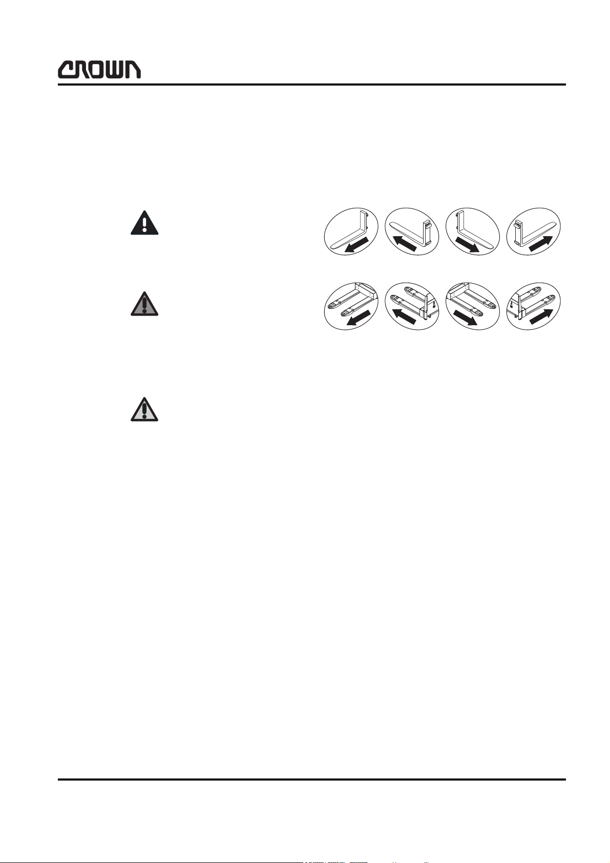
General Symbols
Fork direction
These symbols are used to show the direction of view
in an illustration. The direction of the forks is taken as
reference:
This symbol represents potential minor injuries and/or
potential minor material damage.
You or other people could be slightly injured and/or
minor material damage could occur if you fail to comply
with this safety instruction.
This symbol is used with additional information and
instructions.
WE/WS 2300
Rev. 1 04/2006
3

SAFETY
DANGER
General Safety Instructions
General Safety Instructions
Maintenance and Repair Instructions
Observe the safety instructions in the maintenance
manual and the truck operator manual.
Failure to do so could result in serious or even fatal
injuries to maintenance and other personnel.
Powered trucks can become hazardous if maintenance
and service work are neglected. For this reason maintenance and inspections must be performed at sufficiently short intervals. There must be suitably trained
personnel and proper guidelines at your place of work.
Maintenance and Repairs
Always carry out work in accordance with the test
•
and maintenance schedule contained in this manual and any applicable service bulletins.
• Maintenance and repair work must only be per-
formed by qualified and authorized personnel.
• Keep fire protection equipment at hand and do not
use a naked flame to check fluid levels or to test for
leaks.
• Use groundwater neutral, non-flammable solvents
for cleaning. Always perform cleaning work over an
oil separator. Protect the electrical system against
damp.
• Truck modifications and additions may only be per-
formed with Crown’s prior written approval.
• The reliability, safety and suitability of Crown trucks
can only be ensured by using original Crown parts.
Before Parking the Truck
•
Apply the brake until the truck comes to rest.
• Lower the fork carriage fully.
• Apply the parking brake if applicable.
• Switch off the truck and remove the key.
• When parking on a slope or incline always chock
all wheels.
Before Working on the Truck
•
Jack up the truck so that the drive wheel is clear of
the ground. Apply the Emergency Disconnect and
disconnect the battery.
• Prevent the truck from rolling away and lowering.
• When working on the mast, fork carriage or lifting
mast always apply a chock to prevent accidental
lowering.
• Allow sufficient room for manoeuvre when testing
the truck, to avoid endangering yourself and other
people.
Before Starting the Truck
• Keep the work place and battery charging station
clean, dry and well ventilated.
• Do not allow oils to penetrate the ground or the
drainage system. Used oil must be recycled correctly. Oil filters and dehumidifying inserts must be
treated as special waste. Observe the local authority regulations.
• Spilled battery fluid must be neutralized immedi-
ately and thoroughly rinsed.
• Keep the truck clean. This will facilitate tracing
loose or faulty components.
• Maintain the legibility of the data capacity plate and
data plate, warning and instruction decals.
WE/WS 2300
4
Test the safety mechanisms.
•
• Get into the travel position.
• Test the lifting mechanism, travel switch, speed
control, steering, warning mechanism and brakes.
Warning and Instruction Decals on the Truck
In the course of periodic maintenance work, check that
the warning and instruction decals on the truck are
complete and legible.
• Clean any dirty decals.

• Replace any faulty or missing decals.
A description of the warning and instruction decals
used on the truck and their locations are given in chapter 10.9 of the parts manual.
SAFETY
General Safety Instructions
WE/WS 2300
5

Notes:
6

INTRODUCTION
7

Notes:
8
INTRODUCTION
INFORMATION
General
General
This manual is designed for Customer Service
engineers who wish to familiarise themselves with
maintenance work required for the various truck
components.
It also contains troubleshooting sections which can be
used to identify and remedy faults.
This book is not an operator manual. It is designed
solely for specialist personnel who are trained and
authorised to carry out the work described in the
manual.
Operator Manual
This manual does not contain operating instructions.
An operator manual is supplied with the truck.
Additional copies can be ordered if required.
This manual will help you and your personnel to ensure
the long service life, operational safety and error-free
functioning of your Crown truck.
series. Publications can be obtained from your Crown
dealer or from the following address:
CROWN Gabelstapler GmbH & Co.KG
Moosacher Str. 52
80809 Munich
GERMANY
Tel.: +49 (0)89 / 93 002 -0
Fax: +49 (0)89 / 93 002 -175 or 133
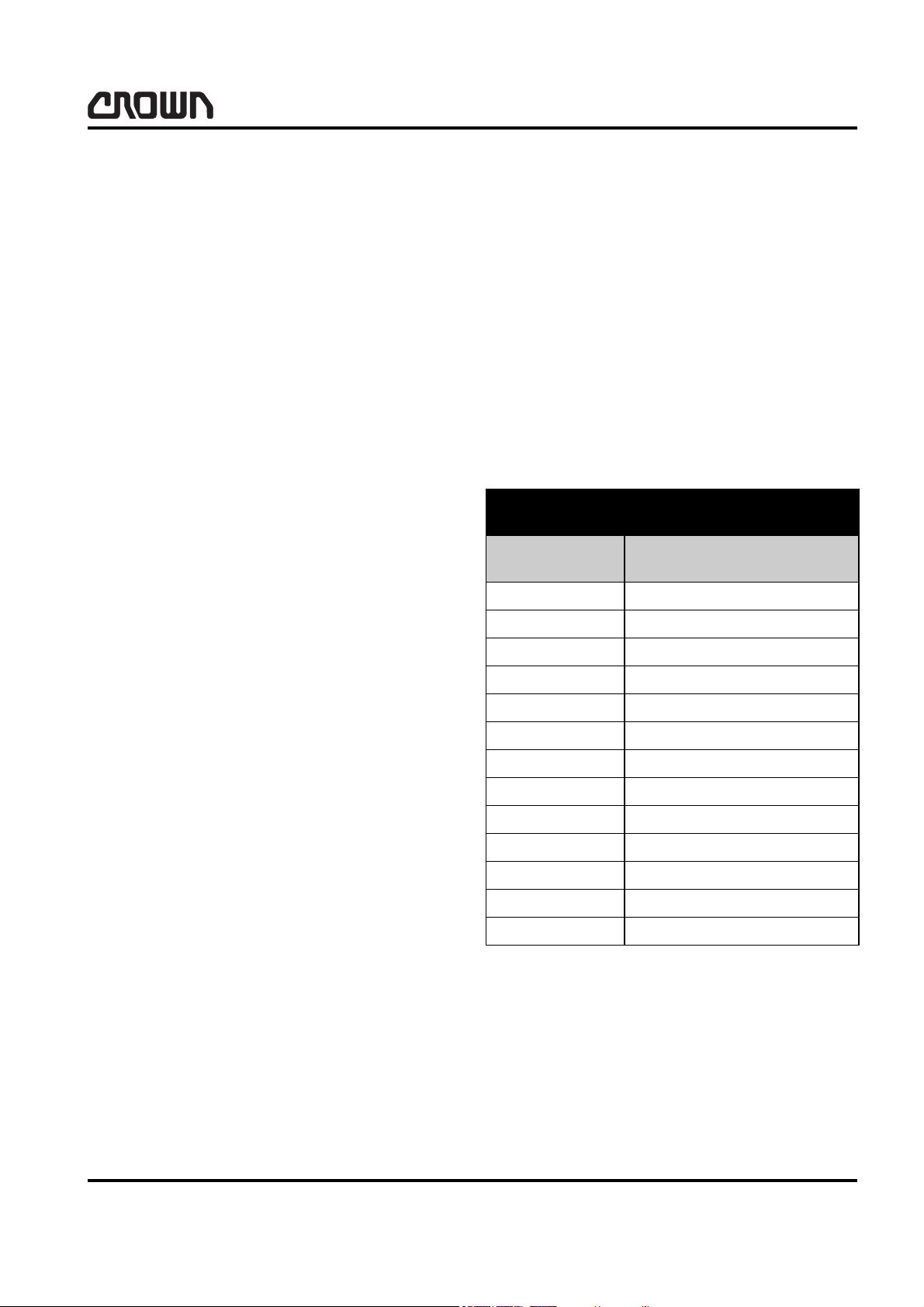
Using the Manual
The manual is divided into chapters. The following
table shows how the manual is structured
Manual structure
Section Table of Contents
IDX Index
MA Safety
Service Training
Crown offers truck-specific training for service
personnel. Contact Crown for details.
Ordering Spare Parts
The maintenance manual does not cover spare parts.
These are listed in a separate parts manual.
Spare parts can be ordered by quoting the:
• Truck specification number
• Truck model number
• Truck serial number
This information can be found on the truck data plate.
Orders can only be processed quickly, correctly and
reliably if the above information is supplied.
Refer to the Technical Specifications sheet for the
utilisable loads, technical data and dimensions for this
ITD Introduction
1 Lubrication & Adjustment
2 Hydraulic System
3 Drive Unit
4 Electrical System
5 Brake System
6Steering
7 Lifting Mechanism
8 Cylinders
9Platform
10 Glossary
WE/WS 2300
9

INTRODUCTION
Models
Models
The manual covers maintenance and repair work for
the following models:
:
WE2300
WS2300
WE2300S
WS2300S
10
WE/WS 2300

LUBRICATION & ADJUSTMENT
11

Notes:
12
 Loading...