

Crown WAVE 50 Series Maintenance Manual

MAINTENANCE MANUAL
WAVE 50 SERIES
Order Number: 812562-006
Revision: A • Printed in Germany

This master maintenance manual is subject to continual updates.
It is meant exclusively for businesses authorized by CROWN.
It is not permitted to pass on the contents or copies thereof to third parties.
CROWN Gabelstapler GmbH & Co. KG
– European Headquarter –
Moosacher Str. 52
80809 München
Germany
Phone +49 (0)89 93 00 2 – 0
Fax +49 (0)89 93 00 2 – 133
All rights reserved under international and Pan-American Copyright Agreement.
Copyright 2005
CROWN Equipment Corporation

TABLE OF CONTENTS
MA- SAFETY INSTRUCTIONS PAGE
General maintenance . . . . . . . . . . . . . . . . . . . . . . . . . . . . . . . . . . . . . . . . . . . . . . . . . . . . . . . . . . . . . . . . 3
Equipment Cleaning . . . . . . . . . . . . . . . . . . . . . . . . . . . . . . . . . . . . . . . . . . . . . . . . . . . . . . . . . . . . . . . . 5
Control of Hazardous Energy . . . . . . . . . . . . . . . . . . . . . . . . . . . . . . . . . . . . . . . . . . . . . . . . . . . . . . . . . 6
2 INTRODUCTION PAGE
®
WAVE
Lockout/Tagout . . . . . . . . . . . . . . . . . . . . . . . . . . . . . . . . . . . . . . . . . . . . . . . . . . . . . . . . . . . . . . . . . . . 6
Operator instructions . . . . . . . . . . . . . . . . . . . . . . . . . . . . . . . . . . . . . . . . . . . . . . . . . . . . . . . . . . . . . 17
Service training . . . . . . . . . . . . . . . . . . . . . . . . . . . . . . . . . . . . . . . . . . . . . . . . . . . . . . . . . . . . . . . . . . 17
Publications . . . . . . . . . . . . . . . . . . . . . . . . . . . . . . . . . . . . . . . . . . . . . . . . . . . . . . . . . . . . . . . . . . . . 17
Vehicle Procedures . . . . . . . . . . . . . . . . . . . . . . . . . . . . . . . . . . . . . . . . . . . . . . . . . . . . . . . . . 5
®
WAVE
Battery . . . . . . . . . . . . . . . . . . . . . . . . . . . . . . . . . . . . . . . . . . . . . . . . . . . . . . . . . . . . . . . . . . . . . . . 6
Hydraulic . . . . . . . . . . . . . . . . . . . . . . . . . . . . . . . . . . . . . . . . . . . . . . . . . . . . . . . . . . . . . . . . . . . . 10
Lifting and blocking . . . . . . . . . . . . . . . . . . . . . . . . . . . . . . . . . . . . . . . . . . . . . . . . . . . . . . . . . . . . 11
Mast . . . . . . . . . . . . . . . . . . . . . . . . . . . . . . . . . . . . . . . . . . . . . . . . . . . . . . . . . . . . . . . . . . . . . . . . 12
Capacitance . . . . . . . . . . . . . . . . . . . . . . . . . . . . . . . . . . . . . . . . . . . . . . . . . . . . . . . . . . . . . . . . . . 14
Data plate . . . . . . . . . . . . . . . . . . . . . . . . . . . . . . . . . . . . . . . . . . . . . . . . . . . . . . . . . . . . . . . . . . . 18
Model number example . . . . . . . . . . . . . . . . . . . . . . . . . . . . . . . . . . . . . . . . . . . . . . . . . . . . . . . . . 18
Vehicle data number example . . . . . . . . . . . . . . . . . . . . . . . . . . . . . . . . . . . . . . . . . . . . . . . . . . . . 19
Work Assist Vehicle . . . . . . . . . . . . . . . . . . . . . . . . . . . . . . . . . . . . . . . . . . . . . . . . . . . . . . 6
M1- LUBRICATION & ADJUSTMENT PAGE
Maintenance program . . . . . . . . . . . . . . . . . . . . . . . . . . . . . . . . . . . . . . . . . . . . . . . . . . . . . . . . . . . . . . 23
Lubricants and maintenance products . . . . . . . . . . . . . . . . . . . . . . . . . . . . . . . . . . . . . . . . . . . . . . . . 24
Component Accessibility . . . . . . . . . . . . . . . . . . . . . . . . . . . . . . . . . . . . . . . . . . . . . . . . . . . . . . . . . . . 25
Chassis . . . . . . . . . . . . . . . . . . . . . . . . . . . . . . . . . . . . . . . . . . . . . . . . . . . . . . . . . . . . . . . . . . . . . . . . 26
Load Deck (1) . . . . . . . . . . . . . . . . . . . . . . . . . . . . . . . . . . . . . . . . . . . . . . . . . . . . . . . . . . . . . . . . 26
Contactor Panel (2) . . . . . . . . . . . . . . . . . . . . . . . . . . . . . . . . . . . . . . . . . . . . . . . . . . . . . . . . . . . . 26
Rear Chassis Cover (3) . . . . . . . . . . . . . . . . . . . . . . . . . . . . . . . . . . . . . . . . . . . . . . . . . . . . . . . . . 26
Service Panel (5) . . . . . . . . . . . . . . . . . . . . . . . . . . . . . . . . . . . . . . . . . . . . . . . . . . . . . . . . . . . . . . 27
MRC Controller . . . . . . . . . . . . . . . . . . . . . . . . . . . . . . . . . . . . . . . . . . . . . . . . . . . . . . . . . . . . . . . 27
Battery Charger . . . . . . . . . . . . . . . . . . . . . . . . . . . . . . . . . . . . . . . . . . . . . . . . . . . . . . . . . . . . . . . 27
Platform/Mast third Stage . . . . . . . . . . . . . . . . . . . . . . . . . . . . . . . . . . . . . . . . . . . . . . . . . . . . . . . . . . 28
Steering Control Pod (2) . . . . . . . . . . . . . . . . . . . . . . . . . . . . . . . . . . . . . . . . . . . . . . . . . . . . . . . . 29
Traction Control Pod (9) . . . . . . . . . . . . . . . . . . . . . . . . . . . . . . . . . . . . . . . . . . . . . . . . . . . . . . . . 29
Mast Cap (10) . . . . . . . . . . . . . . . . . . . . . . . . . . . . . . . . . . . . . . . . . . . . . . . . . . . . . . . . . . . . . . . . 29
Floorboard . . . . . . . . . . . . . . . . . . . . . . . . . . . . . . . . . . . . . . . . . . . . . . . . . . . . . . . . . . . . . . . . . . . 29
Gates . . . . . . . . . . . . . . . . . . . . . . . . . . . . . . . . . . . . . . . . . . . . . . . . . . . . . . . . . . . . . . . . . . . . . . . 29
Lubrication . . . . . . . . . . . . . . . . . . . . . . . . . . . . . . . . . . . . . . . . . . . . . . . . . . . . . . . . . . . . . . . . . . . . . . . 30
Torque Values . . . . . . . . . . . . . . . . . . . . . . . . . . . . . . . . . . . . . . . . . . . . . . . . . . . . . . . . . . . . . . . . . . . . 40
Standard Screws/Bolts . . . . . . . . . . . . . . . . . . . . . . . . . . . . . . . . . . . . . . . . . . . . . . . . . . . . . . . . . . . . 40
Grade . . . . . . . . . . . . . . . . . . . . . . . . . . . . . . . . . . . . . . . . . . . . . . . . . . . . . . . . . . . . . . . . . . . . . . . 40
Torque Chart – Standard Screws/Bolts . . . . . . . . . . . . . . . . . . . . . . . . . . . . . . . . . . . . . . . . . . . . . 40
Self Locking Screw/Nuts . . . . . . . . . . . . . . . . . . . . . . . . . . . . . . . . . . . . . . . . . . . . . . . . . . . . . . . . . . . 41
Grade . . . . . . . . . . . . . . . . . . . . . . . . . . . . . . . . . . . . . . . . . . . . . . . . . . . . . . . . . . . . . . . . . . . . . . . 41
Torque Chart – Self Locking Screws/Nuts . . . . . . . . . . . . . . . . . . . . . . . . . . . . . . . . . . . . . . . . . . . 41
WAVE 50 10/2005 • Printed in Germany
I

M2- HYDRAULIC SYSTEM PAGE
Hydraulic schematic symbols . . . . . . . . . . . . . . . . . . . . . . . . . . . . . . . . . . . . . . . . . . . . . . . . . . . . . . . . 45
Functional Description . . . . . . . . . . . . . . . . . . . . . . . . . . . . . . . . . . . . . . . . . . . . . . . . . . . . . . . . . . . . . . 46
Reservoir . . . . . . . . . . . . . . . . . . . . . . . . . . . . . . . . . . . . . . . . . . . . . . . . . . . . . . . . . . . . . . . . . . . . . . . 46
Hydraulic Oils . . . . . . . . . . . . . . . . . . . . . . . . . . . . . . . . . . . . . . . . . . . . . . . . . . . . . . . . . . . . . . . . . . . . 46
Manual Lowering . . . . . . . . . . . . . . . . . . . . . . . . . . . . . . . . . . . . . . . . . . . . . . . . . . . . . . . . . . . . . . . . . 47
Accumulator Operation . . . . . . . . . . . . . . . . . . . . . . . . . . . . . . . . . . . . . . . . . . . . . . . . . . . . . . . . . . . . 47
Hydraulic Lines and Fittings . . . . . . . . . . . . . . . . . . . . . . . . . . . . . . . . . . . . . . . . . . . . . . . . . . . . . . . . . 48
Lift Relief Valve Setting . . . . . . . . . . . . . . . . . . . . . . . . . . . . . . . . . . . . . . . . . . . . . . . . . . . . . . . . . . . . 49
Accumulator . . . . . . . . . . . . . . . . . . . . . . . . . . . . . . . . . . . . . . . . . . . . . . . . . . . . . . . . . . . . . . . . . . . . . . 50
Precharging . . . . . . . . . . . . . . . . . . . . . . . . . . . . . . . . . . . . . . . . . . . . . . . . . . . . . . . . . . . . . . . . . . . . . 51
Hydraulic Troubleshooting . . . . . . . . . . . . . . . . . . . . . . . . . . . . . . . . . . . . . . . . . . . . . . . . . . . . . . . . . . 52
M3- DRIVE UNIT PAGE
Drive Unit Gearbox Lubrication . . . . . . . . . . . . . . . . . . . . . . . . . . . . . . . . . . . . . . . . . . . . . . . . . . . . . . . 57
Gearbox Replacement . . . . . . . . . . . . . . . . . . . . . . . . . . . . . . . . . . . . . . . . . . . . . . . . . . . . . . . . . . . . . . 60
Wheels . . . . . . . . . . . . . . . . . . . . . . . . . . . . . . . . . . . . . . . . . . . . . . . . . . . . . . . . . . . . . . . . . . . . . . . . . . . 61
Drive Wheel Replacement . . . . . . . . . . . . . . . . . . . . . . . . . . . . . . . . . . . . . . . . . . . . . . . . . . . . . . . . . . 62
Caster Wheel Replacement . . . . . . . . . . . . . . . . . . . . . . . . . . . . . . . . . . . . . . . . . . . . . . . . . . . . . . . . . 63
M4- ELECTRICAL MAINTENANCE PAGE
Component Accessability . . . . . . . . . . . . . . . . . . . . . . . . . . . . . . . . . . . . . . . . . . . . . . . . . . . . . . . . . . . 68
Chassis (under load deck) . . . . . . . . . . . . . . . . . . . . . . . . . . . . . . . . . . . . . . . . . . . . . . . . . . . . . . . . . . 68
Chassis (under platform) . . . . . . . . . . . . . . . . . . . . . . . . . . . . . . . . . . . . . . . . . . . . . . . . . . . . . . . . . . . 70
Steering Control Pod . . . . . . . . . . . . . . . . . . . . . . . . . . . . . . . . . . . . . . . . . . . . . . . . . . . . . . . . . . . . . . 71
Traction Control Pod . . . . . . . . . . . . . . . . . . . . . . . . . . . . . . . . . . . . . . . . . . . . . . . . . . . . . . . . . . . . . . 71
Platform Floor Components . . . . . . . . . . . . . . . . . . . . . . . . . . . . . . . . . . . . . . . . . . . . . . . . . . . . . . . . . 72
Switches . . . . . . . . . . . . . . . . . . . . . . . . . . . . . . . . . . . . . . . . . . . . . . . . . . . . . . . . . . . . . . . . . . . . . . . . . 73
Potentiometers . . . . . . . . . . . . . . . . . . . . . . . . . . . . . . . . . . . . . . . . . . . . . . . . . . . . . . . . . . . . . . . . . . . . 79
POT1 Steering Potentiometer . . . . . . . . . . . . . . . . . . . . . . . . . . . . . . . . . . . . . . . . . . . . . . . . . . . . . . . 79
POT1 Steering Potentiometer Linkage Adjustment . . . . . . . . . . . . . . . . . . . . . . . . . . . . . . . . . . . . . . . 79
POT2 Traction Potentiometer . . . . . . . . . . . . . . . . . . . . . . . . . . . . . . . . . . . . . . . . . . . . . . . . . . . . . . . 81
Fuses . . . . . . . . . . . . . . . . . . . . . . . . . . . . . . . . . . . . . . . . . . . . . . . . . . . . . . . . . . . . . . . . . . . . . . . . . . . . 82
Control Cables . . . . . . . . . . . . . . . . . . . . . . . . . . . . . . . . . . . . . . . . . . . . . . . . . . . . . . . . . . . . . . . . . . . . 84
2135 mm (84 in) Lift Height . . . . . . . . . . . . . . . . . . . . . . . . . . . . . . . . . . . . . . . . . . . . . . . . . . . . . . . . . 84
Control Cable Re-tension . . . . . . . . . . . . . . . . . . . . . . . . . . . . . . . . . . . . . . . . . . . . . . . . . . . . . . . . 85
Cable Replacement . . . . . . . . . . . . . . . . . . . . . . . . . . . . . . . . . . . . . . . . . . . . . . . . . . . . . . . . . . . . 86
2995 mm (118 in) Lift Height . . . . . . . . . . . . . . . . . . . . . . . . . . . . . . . . . . . . . . . . . . . . . . . . . . . . . . . . 88
Control Cable Re-tension . . . . . . . . . . . . . . . . . . . . . . . . . . . . . . . . . . . . . . . . . . . . . . . . . . . . . . . . 89
Cable Replacement . . . . . . . . . . . . . . . . . . . . . . . . . . . . . . . . . . . . . . . . . . . . . . . . . . . . . . . . . . . . 90
Keypad . . . . . . . . . . . . . . . . . . . . . . . . . . . . . . . . . . . . . . . . . . . . . . . . . . . . . . . . . . . . . . . . . . . . . . . . . . . 93
Keypad Programming Features . . . . . . . . . . . . . . . . . . . . . . . . . . . . . . . . . . . . . . . . . . . . . . . . . . . . . . 94
Keypad Specifications . . . . . . . . . . . . . . . . . . . . . . . . . . . . . . . . . . . . . . . . . . . . . . . . . . . . . . . . . . . . . 95
Keypad Block Diagram . . . . . . . . . . . . . . . . . . . . . . . . . . . . . . . . . . . . . . . . . . . . . . . . . . . . . . . . . . 95
Keypad Replacing Key Switch . . . . . . . . . . . . . . . . . . . . . . . . . . . . . . . . . . . . . . . . . . . . . . . . . . . . 95
Part of Platform Wiring Diagram . . . . . . . . . . . . . . . . . . . . . . . . . . . . . . . . . . . . . . . . . . . . . . . . . . . 95
Wiring Color Codes . . . . . . . . . . . . . . . . . . . . . . . . . . . . . . . . . . . . . . . . . . . . . . . . . . . . . . . . . . . . . 96
WAVE 50 10/2005 • Printed in Germany
II

System controller, CURTIS 1703 . . . . . . . . . . . . . . . . . . . . . . . . . . . . . . . . . . . . . . . . . . . . . . . . . . . . . 99
Maintenance . . . . . . . . . . . . . . . . . . . . . . . . . . . . . . . . . . . . . . . . . . . . . . . . . . . . . . . . . . . . . . . . . . . . 99
Safety . . . . . . . . . . . . . . . . . . . . . . . . . . . . . . . . . . . . . . . . . . . . . . . . . . . . . . . . . . . . . . . . . . . . . . 99
Cleaning . . . . . . . . . . . . . . . . . . . . . . . . . . . . . . . . . . . . . . . . . . . . . . . . . . . . . . . . . . . . . . . . . . . . 99
Special Tools . . . . . . . . . . . . . . . . . . . . . . . . . . . . . . . . . . . . . . . . . . . . . . . . . . . . . . . . . . . . . . . . . . 100
Mini Fit Connector . . . . . . . . . . . . . . . . . . . . . . . . . . . . . . . . . . . . . . . . . . . . . . . . . . . . . . . . . . . . 100
Curtis Handset . . . . . . . . . . . . . . . . . . . . . . . . . . . . . . . . . . . . . . . . . . . . . . . . . . . . . . . . . . . . . . . 100
Handset Operation . . . . . . . . . . . . . . . . . . . . . . . . . . . . . . . . . . . . . . . . . . . . . . . . . . . . . . . . . . . . . . 101
Handset Menus . . . . . . . . . . . . . . . . . . . . . . . . . . . . . . . . . . . . . . . . . . . . . . . . . . . . . . . . . . . . . . . . . 103
Program Menu . . . . . . . . . . . . . . . . . . . . . . . . . . . . . . . . . . . . . . . . . . . . . . . . . . . . . . . . . . . . . . . 103
Faults Menu . . . . . . . . . . . . . . . . . . . . . . . . . . . . . . . . . . . . . . . . . . . . . . . . . . . . . . . . . . . . . . . . . 107
Functions Menu . . . . . . . . . . . . . . . . . . . . . . . . . . . . . . . . . . . . . . . . . . . . . . . . . . . . . . . . . . . . . . 108
Information Menu . . . . . . . . . . . . . . . . . . . . . . . . . . . . . . . . . . . . . . . . . . . . . . . . . . . . . . . . . . . . . 108
Programmer Setup Menu . . . . . . . . . . . . . . . . . . . . . . . . . . . . . . . . . . . . . . . . . . . . . . . . . . . . . . 108
Controller Settings . . . . . . . . . . . . . . . . . . . . . . . . . . . . . . . . . . . . . . . . . . . . . . . . . . . . . . . . . . . . . . . . 109
Features and Calibration . . . . . . . . . . . . . . . . . . . . . . . . . . . . . . . . . . . . . . . . . . . . . . . . . . . . . . . . . 110
Handheld Programmer . . . . . . . . . . . . . . . . . . . . . . . . . . . . . . . . . . . . . . . . . . . . . . . . . . . . . . . . . . . 110
Cloning Controllers . . . . . . . . . . . . . . . . . . . . . . . . . . . . . . . . . . . . . . . . . . . . . . . . . . . . . . . . . . . . . . 110
Feature Description . . . . . . . . . . . . . . . . . . . . . . . . . . . . . . . . . . . . . . . . . . . . . . . . . . . . . . . . . . . . . 111
Controller Troubleshooting . . . . . . . . . . . . . . . . . . . . . . . . . . . . . . . . . . . . . . . . . . . . . . . . . . . . . . . . 119
Display Troubleshooting Indicators . . . . . . . . . . . . . . . . . . . . . . . . . . . . . . . . . . . . . . . . . . . . . . . . . . 119
Handset Troubleshooting Aids . . . . . . . . . . . . . . . . . . . . . . . . . . . . . . . . . . . . . . . . . . . . . . . . . . . . . 120
Service Codes . . . . . . . . . . . . . . . . . . . . . . . . . . . . . . . . . . . . . . . . . . . . . . . . . . . . . . . . . . . . . . . . . 121
Hydraulic Interaction . . . . . . . . . . . . . . . . . . . . . . . . . . . . . . . . . . . . . . . . . . . . . . . . . . . . . . . . . . . . . . 142
Static Condition . . . . . . . . . . . . . . . . . . . . . . . . . . . . . . . . . . . . . . . . . . . . . . . . . . . . . . . . . . . . . . . . . 142
Platform Raise . . . . . . . . . . . . . . . . . . . . . . . . . . . . . . . . . . . . . . . . . . . . . . . . . . . . . . . . . . . . . . . . . 144
Platform Lower . . . . . . . . . . . . . . . . . . . . . . . . . . . . . . . . . . . . . . . . . . . . . . . . . . . . . . . . . . . . . . . . 146
Tilt Sensor . . . . . . . . . . . . . . . . . . . . . . . . . . . . . . . . . . . . . . . . . . . . . . . . . . . . . . . . . . . . . . . . . . . . . . 148
Contactor . . . . . . . . . . . . . . . . . . . . . . . . . . . . . . . . . . . . . . . . . . . . . . . . . . . . . . . . . . . . . . . . . . . . . . . 149
Contactor ED (Emergency Disconnect) 24 V . . . . . . . . . . . . . . . . . . . . . . . . . . . . . . . . . . . . . . . . . . 149
Inspection . . . . . . . . . . . . . . . . . . . . . . . . . . . . . . . . . . . . . . . . . . . . . . . . . . . . . . . . . . . . . . . . . . . . . 149
Contacts . . . . . . . . . . . . . . . . . . . . . . . . . . . . . . . . . . . . . . . . . . . . . . . . . . . . . . . . . . . . . . . . . . . 149
Coil . . . . . . . . . . . . . . . . . . . . . . . . . . . . . . . . . . . . . . . . . . . . . . . . . . . . . . . . . . . . . . . . . . . . . . . 149
Component Replacement . . . . . . . . . . . . . . . . . . . . . . . . . . . . . . . . . . . . . . . . . . . . . . . . . . . . . . . . . 150
Contact Replacement . . . . . . . . . . . . . . . . . . . . . . . . . . . . . . . . . . . . . . . . . . . . . . . . . . . . . . . . . 150
Coil Replacement . . . . . . . . . . . . . . . . . . . . . . . . . . . . . . . . . . . . . . . . . . . . . . . . . . . . . . . . . . . . 151
Battery . . . . . . . . . . . . . . . . . . . . . . . . . . . . . . . . . . . . . . . . . . . . . . . . . . . . . . . . . . . . . . . . . . . . . . . . . . 152
Battery Discharge Indicator,
Lift Interrupt . . . . . . . . . . . . . . . . . . . . . . . . . . . . . . . . . . . . . . . . . . . . . . . . . . . . . . . . . . . . . . . . . . . . 152
Battery . . . . . . . . . . . . . . . . . . . . . . . . . . . . . . . . . . . . . . . . . . . . . . . . . . . . . . . . . . . . . . . . . . . . . . . 153
Safety Rules . . . . . . . . . . . . . . . . . . . . . . . . . . . . . . . . . . . . . . . . . . . . . . . . . . . . . . . . . . . . . . . . 154
Inspection . . . . . . . . . . . . . . . . . . . . . . . . . . . . . . . . . . . . . . . . . . . . . . . . . . . . . . . . . . . . . . . . . . 154
Cleaning . . . . . . . . . . . . . . . . . . . . . . . . . . . . . . . . . . . . . . . . . . . . . . . . . . . . . . . . . . . . . . . . . . . 154
Maintenance Free Batteries . . . . . . . . . . . . . . . . . . . . . . . . . . . . . . . . . . . . . . . . . . . . . . . . . . . . . 154
Charger . . . . . . . . . . . . . . . . . . . . . . . . . . . . . . . . . . . . . . . . . . . . . . . . . . . . . . . . . . . . . . . . . . . . . . . 155
Charging Requirements . . . . . . . . . . . . . . . . . . . . . . . . . . . . . . . . . . . . . . . . . . . . . . . . . . . . . . . . 155
Charging . . . . . . . . . . . . . . . . . . . . . . . . . . . . . . . . . . . . . . . . . . . . . . . . . . . . . . . . . . . . . . . . . . . 156
Battery Testing . . . . . . . . . . . . . . . . . . . . . . . . . . . . . . . . . . . . . . . . . . . . . . . . . . . . . . . . . . . . . . . . . 157
Troubleshooting . . . . . . . . . . . . . . . . . . . . . . . . . . . . . . . . . . . . . . . . . . . . . . . . . . . . . . . . . . . . . . . . 158
Motors . . . . . . . . . . . . . . . . . . . . . . . . . . . . . . . . . . . . . . . . . . . . . . . . . . . . . . . . . . . . . . . . . . . . . . . . . . 159
Inspection . . . . . . . . . . . . . . . . . . . . . . . . . . . . . . . . . . . . . . . . . . . . . . . . . . . . . . . . . . . . . . . . . . . . . 159
Traction Motor . . . . . . . . . . . . . . . . . . . . . . . . . . . . . . . . . . . . . . . . . . . . . . . . . . . . . . . . . . . . . . . 159
Lift Pump Motor . . . . . . . . . . . . . . . . . . . . . . . . . . . . . . . . . . . . . . . . . . . . . . . . . . . . . . . . . . . . . . 160
Current Readings . . . . . . . . . . . . . . . . . . . . . . . . . . . . . . . . . . . . . . . . . . . . . . . . . . . . . . . . . . . . . 160
WAVE 50 10/2005 • Printed in Germany
III

Service Panel . . . . . . . . . . . . . . . . . . . . . . . . . . . . . . . . . . . . . . . . . . . . . . . . . . . . . . . . . . . . . . . . . . . . . 161
M5- BRAKE MAINTENANCE PAGE
Brake System . . . . . . . . . . . . . . . . . . . . . . . . . . . . . . . . . . . . . . . . . . . . . . . . . . . . . . . . . . . . . . . . . . . . 167
Regenerative Braking . . . . . . . . . . . . . . . . . . . . . . . . . . . . . . . . . . . . . . . . . . . . . . . . . . . . . . . . . . . . 167
Parking brake . . . . . . . . . . . . . . . . . . . . . . . . . . . . . . . . . . . . . . . . . . . . . . . . . . . . . . . . . . . . . . . . . . . 167
Parking Brake Wear . . . . . . . . . . . . . . . . . . . . . . . . . . . . . . . . . . . . . . . . . . . . . . . . . . . . . . . . . . . 168
M7- MAST MAINTENANCE PAGE
2135 mm (84 in) Lift Height . . . . . . . . . . . . . . . . . . . . . . . . . . . . . . . . . . . . . . . . . . . . . . . . . . . . . . . . . 170
Torque Requirements . . . . . . . . . . . . . . . . . . . . . . . . . . . . . . . . . . . . . . . . . . . . . . . . . . . . . . . . . . . . 171
Mast Disassembly . . . . . . . . . . . . . . . . . . . . . . . . . . . . . . . . . . . . . . . . . . . . . . . . . . . . . . . . . . . . . . . 171
Mast Maintenance . . . . . . . . . . . . . . . . . . . . . . . . . . . . . . . . . . . . . . . . . . . . . . . . . . . . . . . . . . . . . . . 172
Mast Assembly . . . . . . . . . . . . . . . . . . . . . . . . . . . . . . . . . . . . . . . . . . . . . . . . . . . . . . . . . . . . . . . . . . 172
Mast Reshimming . . . . . . . . . . . . . . . . . . . . . . . . . . . . . . . . . . . . . . . . . . . . . . . . . . . . . . . . . . . . . . . 176
Top Shims and Guides . . . . . . . . . . . . . . . . . . . . . . . . . . . . . . . . . . . . . . . . . . . . . . . . . . . . . . . . . 176
Bottom Shims and Guides . . . . . . . . . . . . . . . . . . . . . . . . . . . . . . . . . . . . . . . . . . . . . . . . . . . . . . 179
2995 mm (118 in) Lift Height . . . . . . . . . . . . . . . . . . . . . . . . . . . . . . . . . . . . . . . . . . . . . . . . . . . . . . . . 180
Torque Requirements . . . . . . . . . . . . . . . . . . . . . . . . . . . . . . . . . . . . . . . . . . . . . . . . . . . . . . . . . . . . 181
Mast Disassembly . . . . . . . . . . . . . . . . . . . . . . . . . . . . . . . . . . . . . . . . . . . . . . . . . . . . . . . . . . . . . . . 181
Mast Maintenance . . . . . . . . . . . . . . . . . . . . . . . . . . . . . . . . . . . . . . . . . . . . . . . . . . . . . . . . . . . . . . . 183
Mast Assembly . . . . . . . . . . . . . . . . . . . . . . . . . . . . . . . . . . . . . . . . . . . . . . . . . . . . . . . . . . . . . . . . . . 183
Mast Reshimming . . . . . . . . . . . . . . . . . . . . . . . . . . . . . . . . . . . . . . . . . . . . . . . . . . . . . . . . . . . . . 188
Top Shims and Guides . . . . . . . . . . . . . . . . . . . . . . . . . . . . . . . . . . . . . . . . . . . . . . . . . . . . . . . . . 188
Bottom Shims and Guides . . . . . . . . . . . . . . . . . . . . . . . . . . . . . . . . . . . . . . . . . . . . . . . . . . . . . . 191
Lift Chain . . . . . . . . . . . . . . . . . . . . . . . . . . . . . . . . . . . . . . . . . . . . . . . . . . . . . . . . . . . . . . . . . . . . . . . . 192
Inspection . . . . . . . . . . . . . . . . . . . . . . . . . . . . . . . . . . . . . . . . . . . . . . . . . . . . . . . . . . . . . . . . . . . . . 192
Wear . . . . . . . . . . . . . . . . . . . . . . . . . . . . . . . . . . . . . . . . . . . . . . . . . . . . . . . . . . . . . . . . . . . . . . . 192
Rust and Corrosion . . . . . . . . . . . . . . . . . . . . . . . . . . . . . . . . . . . . . . . . . . . . . . . . . . . . . . . . . . . . 193
Cracked Plates . . . . . . . . . . . . . . . . . . . . . . . . . . . . . . . . . . . . . . . . . . . . . . . . . . . . . . . . . . . . . . . 193
Tight Joints . . . . . . . . . . . . . . . . . . . . . . . . . . . . . . . . . . . . . . . . . . . . . . . . . . . . . . . . . . . . . . . . . . 194
Protruding or Turned Pins . . . . . . . . . . . . . . . . . . . . . . . . . . . . . . . . . . . . . . . . . . . . . . . . . . . . . . . 194
Chain Side Wear . . . . . . . . . . . . . . . . . . . . . . . . . . . . . . . . . . . . . . . . . . . . . . . . . . . . . . . . . . . . . . 194
Lift Chain Lubrication . . . . . . . . . . . . . . . . . . . . . . . . . . . . . . . . . . . . . . . . . . . . . . . . . . . . . . . . . . . . . 195
Lift Chain Replacement . . . . . . . . . . . . . . . . . . . . . . . . . . . . . . . . . . . . . . . . . . . . . . . . . . . . . . . . . . . 195
Lift Chain Removal . . . . . . . . . . . . . . . . . . . . . . . . . . . . . . . . . . . . . . . . . . . . . . . . . . . . . . . . . . . . 195
Secondary Chain Replacement . . . . . . . . . . . . . . . . . . . . . . . . . . . . . . . . . . . . . . . . . . . . . . . . . .198
Leaf Chain Disconnect . . . . . . . . . . . . . . . . . . . . . . . . . . . . . . . . . . . . . . . . . . . . . . . . . . . . . . . . . 200
M8- CYLINDER MAINTENANCE PAGE
General . . . . . . . . . . . . . . . . . . . . . . . . . . . . . . . . . . . . . . . . . . . . . . . . . . . . . . . . . . . . . . . . . . . . . . . . . . 203
Cylinder Removal . . . . . . . . . . . . . . . . . . . . . . . . . . . . . . . . . . . . . . . . . . . . . . . . . . . . . . . . . . . . . . . . . 204
Disassembly . . . . . . . . . . . . . . . . . . . . . . . . . . . . . . . . . . . . . . . . . . . . . . . . . . . . . . . . . . . . . . . . . . . . 206
Hydraulic Seals . . . . . . . . . . . . . . . . . . . . . . . . . . . . . . . . . . . . . . . . . . . . . . . . . . . . . . . . . . . . . . . . . 207
Hydraulic Seal Installation . . . . . . . . . . . . . . . . . . . . . . . . . . . . . . . . . . . . . . . . . . . . . . . . . . . . . . 207
Cylinder Replacement . . . . . . . . . . . . . . . . . . . . . . . . . . . . . . . . . . . . . . . . . . . . . . . . . . . . . . . . . . . . . 210
Velocity Fuse Replacement . . . . . . . . . . . . . . . . . . . . . . . . . . . . . . . . . . . . . . . . . . . . . . . . . . . . . . . . 213
Cylinder Bleeding . . . . . . . . . . . . . . . . . . . . . . . . . . . . . . . . . . . . . . . . . . . . . . . . . . . . . . . . . . . . . . . . 214
Cylinder Summary . . . . . . . . . . . . . . . . . . . . . . . . . . . . . . . . . . . . . . . . . . . . . . . . . . . . . . . . . . . . . . . 214
WAVE 50 10/2005 • Printed in Germany
IV

M9- PLATFORM MAINTENANCE PAGE
Load Tray . . . . . . . . . . . . . . . . . . . . . . . . . . . . . . . . . . . . . . . . . . . . . . . . . . . . . . . . . . . . . . . . . . . . . . . 217
Operation . . . . . . . . . . . . . . . . . . . . . . . . . . . . . . . . . . . . . . . . . . . . . . . . . . . . . . . . . . . . . . . . . . . 217
Load Tray Disassembly . . . . . . . . . . . . . . . . . . . . . . . . . . . . . . . . . . . . . . . . . . . . . . . . . . . . . . . . 219
Load Tray Assembly . . . . . . . . . . . . . . . . . . . . . . . . . . . . . . . . . . . . . . . . . . . . . . . . . . . . . . . . . . 219
M10-GLOSSARY PAGE
Audible Indicators . . . . . . . . . . . . . . . . . . . . . . . . . . . . . . . . . . . . . . . . . . . . . . . . . . . . . . . . . . . . . . . 224
Battery . . . . . . . . . . . . . . . . . . . . . . . . . . . . . . . . . . . . . . . . . . . . . . . . . . . . . . . . . . . . . . . . . . . . . . . 224
Connections . . . . . . . . . . . . . . . . . . . . . . . . . . . . . . . . . . . . . . . . . . . . . . . . . . . . . . . . . . . . . . . . . . . 225
Contactors/Relays . . . . . . . . . . . . . . . . . . . . . . . . . . . . . . . . . . . . . . . . . . . . . . . . . . . . . . . . . . . . . . 228
Diode Blocks . . . . . . . . . . . . . . . . . . . . . . . . . . . . . . . . . . . . . . . . . . . . . . . . . . . . . . . . . . . . . . . . . . . 229
Fuses . . . . . . . . . . . . . . . . . . . . . . . . . . . . . . . . . . . . . . . . . . . . . . . . . . . . . . . . . . . . . . . . . . . . . . . . 229
Lights . . . . . . . . . . . . . . . . . . . . . . . . . . . . . . . . . . . . . . . . . . . . . . . . . . . . . . . . . . . . . . . . . . . . . . . . 230
Miscellaneous . . . . . . . . . . . . . . . . . . . . . . . . . . . . . . . . . . . . . . . . . . . . . . . . . . . . . . . . . . . . . . . . . . 231
Solenoid Valves . . . . . . . . . . . . . . . . . . . . . . . . . . . . . . . . . . . . . . . . . . . . . . . . . . . . . . . . . . . . . . . . 234
Suppressor Blocks . . . . . . . . . . . . . . . . . . . . . . . . . . . . . . . . . . . . . . . . . . . . . . . . . . . . . . . . . . . . . . 234
Switches . . . . . . . . . . . . . . . . . . . . . . . . . . . . . . . . . . . . . . . . . . . . . . . . . . . . . . . . . . . . . . . . . . . . . . 235
System/Modules . . . . . . . . . . . . . . . . . . . . . . . . . . . . . . . . . . . . . . . . . . . . . . . . . . . . . . . . . . . . . . . . 241
DIA- ELECTRICAL DIAGRAMS PAGE
Diagrams (2135 mm, 84 in) . . . . . . . . . . . . . . . . . . . . . . . . . . . . . . . . . . . . . . . . . . . . . . . . . . . . . . . . . 245
Block Diagram . . . . . . . . . . . . . . . . . . . . . . . . . . . . . . . . . . . . . . . . . . . . . . . . . . . . . . . . . . . . . . . . . . . 246
Schematic . . . . . . . . . . . . . . . . . . . . . . . . . . . . . . . . . . . . . . . . . . . . . . . . . . . . . . . . . . . . . . . . . . . . . . . 247
Platform . . . . . . . . . . . . . . . . . . . . . . . . . . . . . . . . . . . . . . . . . . . . . . . . . . . . . . . . . . . . . . . . . . . . . . . . 248
Chassis . . . . . . . . . . . . . . . . . . . . . . . . . . . . . . . . . . . . . . . . . . . . . . . . . . . . . . . . . . . . . . . . . . . . . . . . . 249
Contactor Panel . . . . . . . . . . . . . . . . . . . . . . . . . . . . . . . . . . . . . . . . . . . . . . . . . . . . . . . . . . . . . . . . . . 250
Power Cables . . . . . . . . . . . . . . . . . . . . . . . . . . . . . . . . . . . . . . . . . . . . . . . . . . . . . . . . . . . . . . . . . . . . 251
Wire Harnesses . . . . . . . . . . . . . . . . . . . . . . . . . . . . . . . . . . . . . . . . . . . . . . . . . . . . . . . . . . . . . . . . . . 252
Diagrams (2995 mm, 118 in) . . . . . . . . . . . . . . . . . . . . . . . . . . . . . . . . . . . . . . . . . . . . . . . . . . . . . . . . 253
Block Diagram . . . . . . . . . . . . . . . . . . . . . . . . . . . . . . . . . . . . . . . . . . . . . . . . . . . . . . . . . . . . . . . . . . . 254
Schematic . . . . . . . . . . . . . . . . . . . . . . . . . . . . . . . . . . . . . . . . . . . . . . . . . . . . . . . . . . . . . . . . . . . . . . . 255
Platform . . . . . . . . . . . . . . . . . . . . . . . . . . . . . . . . . . . . . . . . . . . . . . . . . . . . . . . . . . . . . . . . . . . . . . . . 256
Chassis . . . . . . . . . . . . . . . . . . . . . . . . . . . . . . . . . . . . . . . . . . . . . . . . . . . . . . . . . . . . . . . . . . . . . . . . . 257
Contactor Panel . . . . . . . . . . . . . . . . . . . . . . . . . . . . . . . . . . . . . . . . . . . . . . . . . . . . . . . . . . . . . . . . . . 258
Power Cables . . . . . . . . . . . . . . . . . . . . . . . . . . . . . . . . . . . . . . . . . . . . . . . . . . . . . . . . . . . . . . . . . . . . 259
Wire Harnesses . . . . . . . . . . . . . . . . . . . . . . . . . . . . . . . . . . . . . . . . . . . . . . . . . . . . . . . . . . . . . . . . . . 260
WAVE 50 10/2005 • Printed in Germany
V

VI
WAVE 50 10/2005 • Printed in Germany

Printed in Germany
SAFETY INSTRUCTIONS
1

SAFETY INSTRUCTIONS
Notice:
Printed in Germany
2
SAFETY INSTRUCTIONS
General maintenance
General maintenance
Warning!
These vehicles may become hazardous if adequate
maintenance is neglected. Therefore, adequate maintenance facilities, trained personnel and procedures
should be provided.
Maintenance and inspection shall be performed in conformance with the following practices:
z A scheduled planned maintenance, lubrication and
inspection system should be followed.
z Only qualified and authorized personnel shall be
permitted to maintain, repair, adjust and inspect
vehicle.
z Before leaving the vehicle:
– Stop the vehicle.
– Fully lower the platform.
Risk of accident!
To prevent serious risk of injury
to yourself and others observe
the following safety instructions.
– Use chocks or other positive positioning de-
vices.
– Block load engaging means, inter masts or
chassis before working under them.
– Operation to check performance of vehicle or
attachments shall be conducted in an authorized safe clearance area.
z Before starting to operate the vehicle:
– Be in operating position.
– Place directional control in neutral.
– Before operating the vehicle, check the func-
tions of lift systems, directional control, speed
control, steering, warning devices and brakes.
Warning!
Fire hazard!
Fire or flame can cause severe
personal injury or property
damage.
Do not use an open flame to
check level or for leakage of
electrolyte and fluids or oil.
Do not use open pans of fuel or
flammable cleaning fluids for
cleaning parts.
– Place directional controls in neutral.
– Turn off power (Battery disconnect).
– Remove key.
– Block the wheels if vehicle is on an incline.
z Before working on the vehicle
– Raise drive wheels free of floor or disconnect
power sources.
z Avoid fire hazards and have fire protection equip-
ment present.
z Keep shop well ventilated, clean and dry.
z Brakes, steering mechanisms, control mecha-
nisms, guards and safety devices shall be inspected regularly and maintained in a safe operating condition.
WAVE 50 10/2005 • Printed in Germany
MA-2450
02 Rev. 12/01
3

SAFETY INSTRUCTIONS
General maintenance
z Capacity, operation and maintenance instruction
plates or decals shall be maintained in legible condition.
z All parts of lift mechanisms shall be inspected to
maintain them in safe operating condition.
z All hydraulic systems shall be regularly inspected
and maintained in conformance with good practice.
Cylinders, valves and other similar parts shall be
checked to assure that “drift” has not developed to
the extent that it would create a hazard.
z Batteries, motors, controllers, limit switches, pro-
tective devices, electrical conductors and connections shall be maintained in conformance with
good practice. Special attention shall be paid to the
condition of electrical insulation.
z Vehicles shall be kept in a clean condition to mini-
mize fire hazards and facilitate detection of loose
or defective parts.
z Modifications and additions which affect capacity
and safe vehicle operation shall not be performed
by the customer or user without manufacturers
prior written approval. Capacity, operation and
maintenance plates or decals shall be changed accordingly.
z Care shall be taken to assure that all replacement
parts are interchangeable with the original parts
and of equal quality to that provided in the original
equipment.
z Be sure that any equipment added to the truck (ter-
minal, fan, clipboard, etc.) is positioned so that it
does not block your vision or interfere with safe and
efficient operation of the truck.
MA-2450
4
WAVE 50 10/2005 • Printed in Germany
02 Rev. 12/01
SAFETY INSTRUCTIONS
Equipment Cleaning
Equipment Cleaning
WAVE® Vehicle Procedures
z Prefer dry pressured air for cleaning built up dirt
and dust from electric material handling equipment.
z For localized degreasing use of an appropriate sol-
vent such as "TOUGH ON GREASE" (Crown P/N
063009-005) is recommended.
If these methods are not effective and power washing
is the only alternative, extreme care must be exercised.
Caution!
Risk of damage!
Power washing or cleaning solvents can damage electrical
components including connectors, terminal boards and wiring.
Mineral and chemical residue
left on or in components (i.e. circuit boards, contactors, encoders, switches, potentiometers,
etc.) after washing is a proponent of oxidation and corrosion.
All electronic components including motors must be protected or even removed to eliminate the risk of damage.
Functional integrity of contaminated components may
be questionable. Nuisance fault logging, intermittent
operation or immediate failure could be the resultant of
power washing.
Power washing will also remove and/or destroy lubricants in or on the surface of shafts, unsealed bearings,
hinges, exposed gears, bushings, chains, linkages,
etc.
z These items must also be protected before clean-
ing or properly lubricated after cleaning.
Consideration must also be given to metal surfaces.
The cleaning process can strip away paint and protective coatings applied to components (i.e. hydraulic
lines, terminal strips, linkages) for freezer/corrosion environment.
z Paint and/or protective coating must be reapplied
to these areas to reduce the chance of oxidation
and corrosion.
z Remove solvent residue and dry the component
thoroughly before installing removed components,
lubricating or returning the equipment to service.
WAVE 50 10/2005 • Printed in Germany
MA-2450
5

SAFETY INSTRUCTIONS
Control of Hazardous Energy
Control of Hazardous Energy
Lockout/Tagout
WAVE® Work Assist Vehicle
In the interest of safety and to ensure compliance with
the OSHA Regulations, (Standards - 29 CFR), The
control of hazardous energy (lockout/tagout) -
1910.147, Crown has developed guidelines for proper
energy control when performing service and maintenance on the WAVE.
z Review the appropriate sections in this service
manual for additional procedures to be followed,
before performing any service or maintenance on
the WAVE.
In addition, Crown recommends that all mechanics
wear appropriate protective items, such as safety
glasses, work gloves, and steel toed shoes, whenever
performing service or maintenance work on Crown
equipment.
Battery
z If electrolyte comes in contact with eyes, flush im-
mediately and thoroughly with clean water. Obtain
medical attention immediately.
z Should electrolyte be spilled on skin, rinse
promptly with clean water and wash with soap.
z A baking soda solution (one pound to one gallon of
water) will neutralize acid spilled on clothing, floor
or any other surface. Apply solution until bubbling
stops and rinse with clean water.
z Keep vent plugs firmly in place at all times except
when adding water or taking hydrometer readings.
Danger!
This gas remains in the battery cells long after charging
has stopped.
Risk of explosion!
Gas formed during charging is
highly explosive and can cause
serious personal injury. There
also may be a danger of release
of harmful substances.
Never smoke or bring flame
near the battery.
Safety rules
Warning!
Risk of injury!
Electrolyte contained in batteries can cause severe personal
injury or property damage if
coming in contact with eyes,
skin, clothing or floor
Avoid any contact of electrolyte
with eyes or skin
Wear protective clothing, such
as, rubber apron, gloves, boots
and full face shield when performing any maintenance on
batteries
Warning!
z Do not allow dirt, cleaning solution or other foreign
material to enter cells. Impurities in electrolyte has
a neutralizing effect reducing available charge.
z If battery repair is planned, follow the battery man-
ufacturer's instructions concerning repair practices
and procedures.
Risk of arcing!
Do not lay metallic or conductive objects on battery. Otherwise arcing will result and
cause property damage.
MA-2450
6
WAVE 50 10/2005 • Printed in Germany
SAFETY INSTRUCTIONS
Control of Hazardous Energy
Charging
Warning!
z Make certain the charger being used matches the
voltage and amperage of the truck battery. This
voltage is listed on the truck serial plate.
Caution!
Danger!
Risk of property damage!
NEVER operate truck with an
undersized battery, otherwise
the truck can be seriously damaged.
Make certain battery used
meets weight, size and voltage
requirements of truck (refer to
serial plate).
Risk of injury!
Unauthorised component removal or improper maintenance
can result in significant danger
to the user.
Only qualified and experienced
personnel should perform
maintenance and repair on batteries.
Risk of accident!
Current flowing between battery
and charger can cause shock
hazard and result in serious injury to you, the battery and
charger.
NEVER connect or disconnect
batteries to a charger while the
charger is “ON”.
Make sure the charger is “OFF”
before disconnecting or connecting batteries.
Caution!
Warning!
Never use a match or lighter. Battery fumes are explosive.
z Consult the charger manufacturer’s manual cover-
ing your charger for hints on operation and maintenance.
Risk of injury!
Unauthorised component removal or improper maintenance
can result in significant danger
to the user.
Only qualified and experienced
personnel should perform
maintenance and repair on batteries.
Risk of explosion!
Gas formed during charging is
highly explosive and can cause
serious personal injury. There
also may be a danger of release
of harmful substances.
Never smoke or bring flame
near the battery.
z Make certain battery used meets weight, size and
voltage requirements of truck (refer to serial plate).
NEVER operate truck with an undersized battery.
WAVE 50 10/2005 • Printed in Germany
MA-2450
7
SAFETY INSTRUCTIONS
Control of Hazardous Energy
Battery removal
Caution!
When removing a battery, move truck to area intended
for battery care. Floor must be level.
Turn keyswitch or toggle switch to "off" position and remove key. Disconnect battery and lockout or tagout
truck as described in Battery - Lockout/Tagout in this
section. Lower load engaging means completely.
Risk of short-circuit!
Do not allow any metallic object
to come in contact with the top
of the battery cells. This may
cause a short circuit when removing, transporting a battery.
Use an insulator (such as plywood, plastic caps) to cover the
top of battery posts before and
during removal.
Battery installation
Warning!
Caution!
Risk of injury!
A non-stable or rolling truck
may cause injury to you or others.
When installing a battery, move
truck to area intended for battery care.
Floor must be level.
Turn keyswitch or toggle switch
to "off" position and remove
key.
Risk of short-circuit!
Do not allow any metallic object
to come in contact with the top
of the battery cells. This may
cause a short circuit when removing, transporting a battery.
Use an insulator (such as plywood, plastic caps) to cover the
top of battery posts before and
during removal.
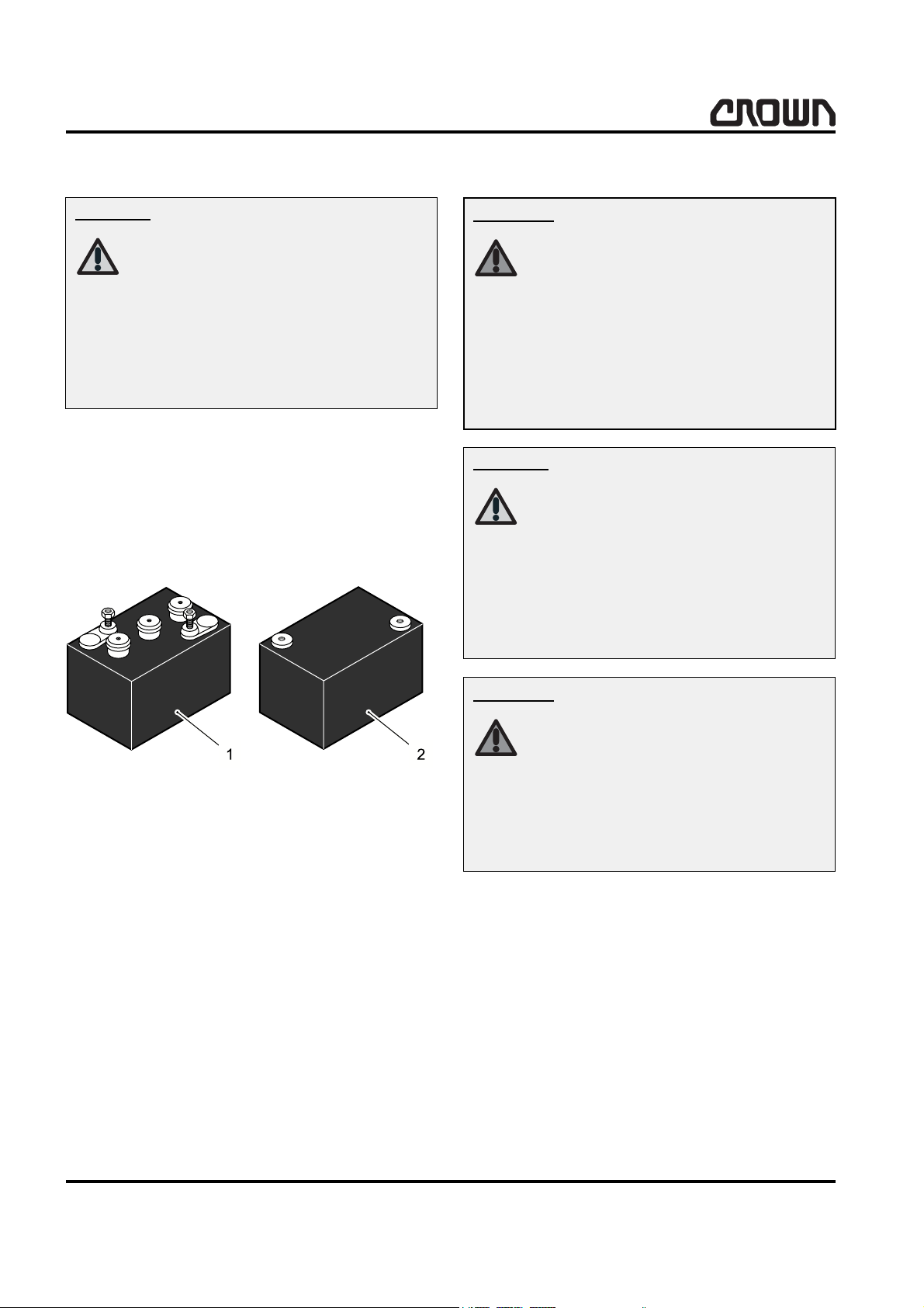
1 Wet cell battery
2 Maintenance free battery
12024
Warning!
z Lockout or tagout truck as described in Battery -
Lockout/Tagout in this section.
Risk of property damage!
NEVER operate truck with an
undersized battery, otherwise
the truck can be seriously damaged.
Make certain battery used
meets weight, size and voltage
requirements of truck (refer to
serial plate).
MA-2450
8
WAVE 50 10/2005 • Printed in Germany
SAFETY INSTRUCTIONS
Control of Hazardous Energy
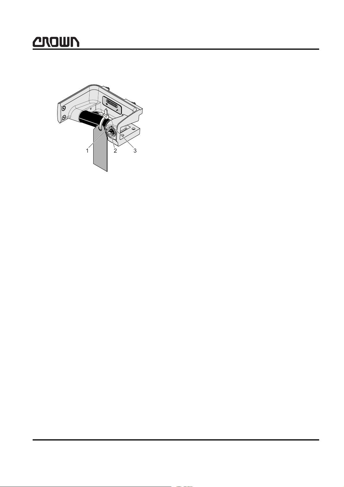
Battery Lockout/Tagout
1 Key switch, OFF
2Key
3 Key switch, ON
When maintenance is performed and the batteries are
removed from the truck:
z remove the main power fuses,
z install a lockout device on the trucks battery con-
nector if possible,
z or if possible install a tag with a cable tie on the
trucks battery connector so it cannot be removed
!
53
easily warning that the truck is not available for operation.
MS-2450-002
z Always turn key (2) switch to "off" (1), remove key
(2) and apply tag to steering pod with cable tie
warning others truck is being serviced.
When maintenance is performed and the batteries are
left in the truck:
z disconnect batteries,
z remove the main power fuses and
z install a commercially available lockout device on
battery connector.
WAVE 50 10/2005 • Printed in Germany
MA-2450
9
SAFETY INSTRUCTIONS
Control of Hazardous Energy
Hydraulic
Danger!
Any fluid injected into the skin under high pressure
should be considered as a serious medical emergency
despite an initial normal appearance of the skin. There
is a delayed onset of pain, and serious tissue damage
may occur. Medical attention should be sought immediately by a specialist who has had experience with this
type of injury.
Risk of accident: high pressure
fluid!
Escaping fluid under pressure
can penetrate the skin causing
serious injury.
Relieve pressure before disconnecting hydraulic lines.
Tighten all connections before
applying pressure.
Keep hands and body away
from pin holes which eject fluids under high pressure.
Use a piece of cardboard or paper to search for leaks.
Do not use your hand.
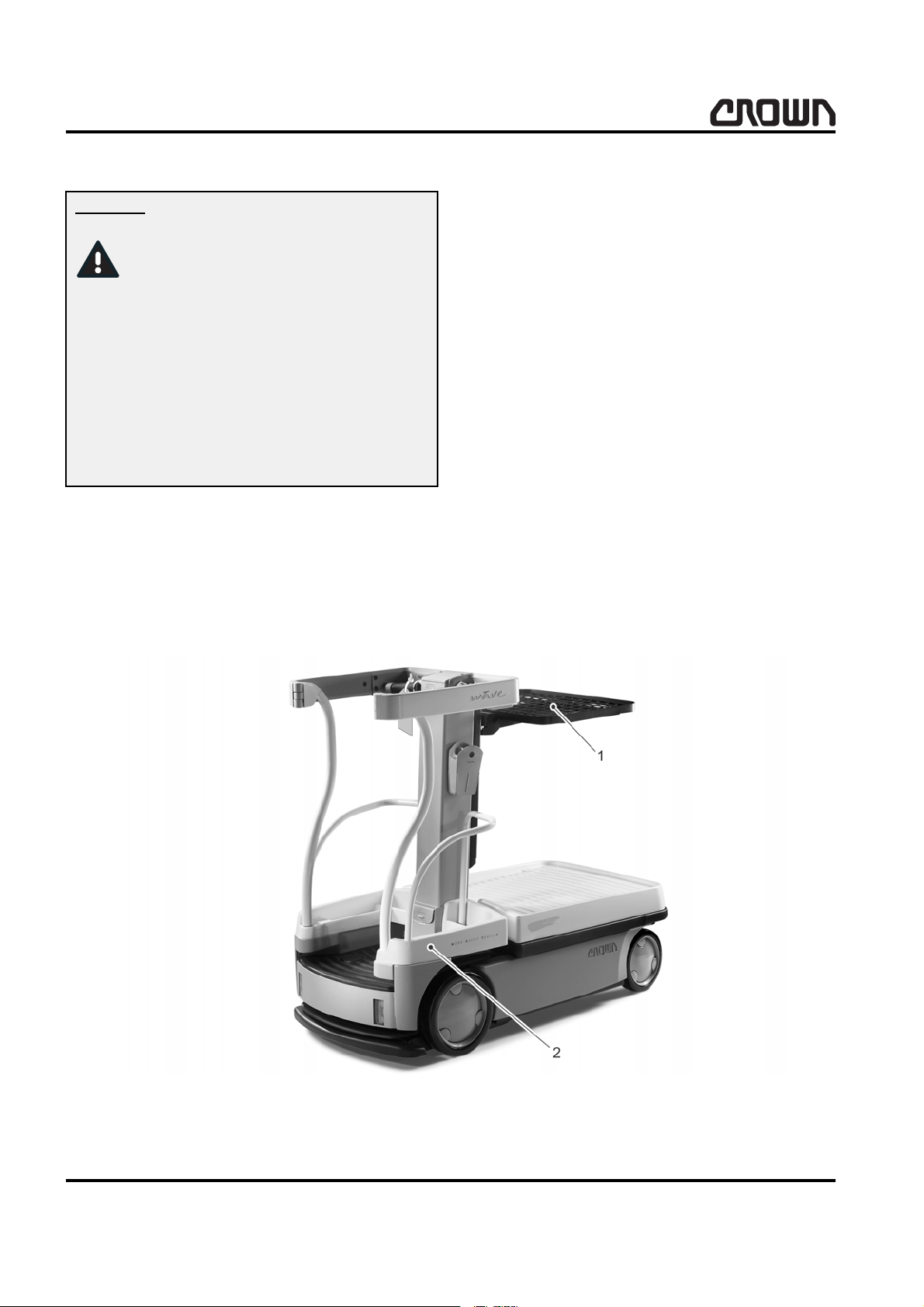
When maintenance is to be performed on the hydraulic
system, make sure the hydraulic system is not under
pressure:
z Move truck to a secure non traffic maintenance
area with a level floor.
z No load on load tray (1).
z Completely lower load engaging means or, if re-
quired for maintenance, block truck at appropriate
height as described in Lifting and blocking,
page 11.
z Actuate the hydraulic switch to remove any hy-
draulic pressure that may be present.
z Lockout or tagout truck as described in Battery
Lockout/Tagout in this section.
1 Load tray 2 Platform
MA-2450
10
MS-2450-003
WAVE 50 10/2005 • Printed in Germany
SAFETY INSTRUCTIONS
Control of Hazardous Energy
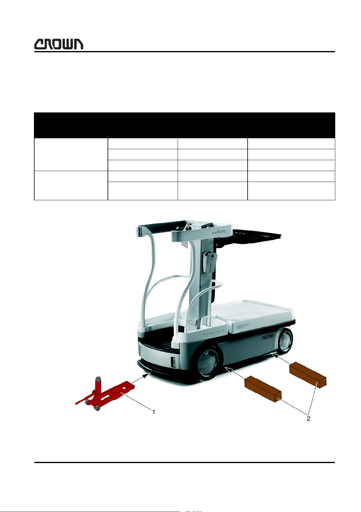
Lifting and blocking
z Move vehicle to a secure non traffic maintenance
area with a level floor.
Tool Properties Value Crown Part
Capacity: 3620 kg (8000 lb) 122599
Hydraulik Jack
Hardwood blocks
Collapsed height (min.): 60 mm (2.25 in)
Raised height maximum: 400 mm (16 in)
Quantity 2
Dimensions: 100 x 100 x 762 mm
z No load on load tray.
z Lower platform completely.
z Lockout or tagout vehicle as described in Battery -
Lockout/Tagout in this section.
number
(4 x 4 x 30 in)
1 Hydraulic jack 2 Hardwood block
WAVE 50 10/2005 • Printed in Germany
12027
MA-2450
11
SAFETY INSTRUCTIONS
Control of Hazardous Energy
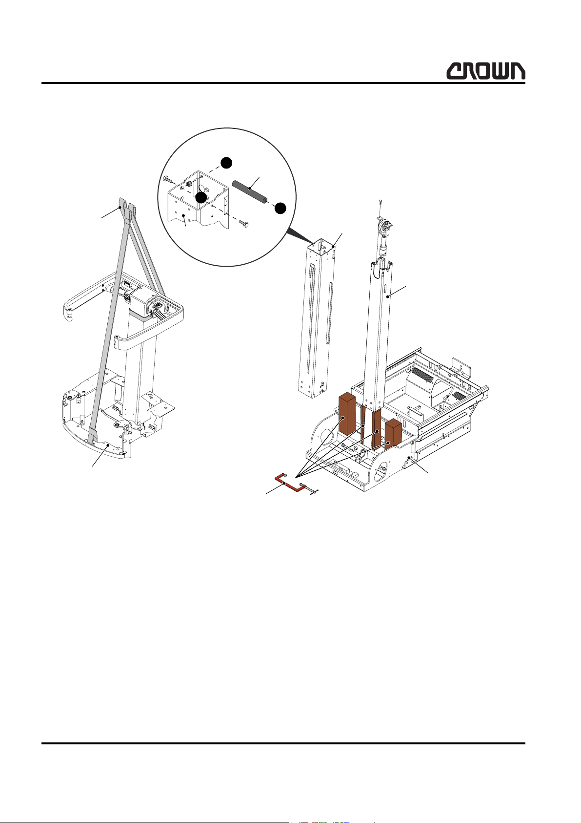
Mast
&
)
)
1 Straps 6 Second Stage Mast
2Platform 7Chassis
3 Third Stage Mast 8 Hardwood Block
4 Part of Third Stage Mast 9 Clamping Tool
5 Lifting Tool
2YHUKHDG9LHZ
/HIW
5HDU
)URQW
5LJKW
12028
MA-2450
12
WAVE 50 10/2005 • Printed in Germany
SAFETY INSTRUCTIONS
Control of Hazardous Energy
z Move vehicle to a secure non traffic maintenance
area with a level floor.
z Raise platform (2) to height necessary.
z Block the second stage mast (6) and platform (2)
using the appropriate length and size hardwood
blocks (8).
Tool Dimensions
100 x 100 mm [4 x 4 in]
Hardwood blocks
50 x 100 mm [2 x 4 in])
z Clamp hardwood blocks (8) to chassis (7), lower
platform (2).
z Disconnect electrical and chain connections nec-
essary to remove platform (2), third stage mast (3)
and second stage mast (6).
z Remove guides and shims necessary to remove
platform (2), third stage mast (3) and second stage
mast (6).
z Insert lifting tool (5) into top of third stage mast (3)
to assist in removing third stage mast (3).
z Lockout or tagout vehicle as described in Battery -
Lockout/Tagout in this section.
WAVE 50 10/2005 • Printed in Germany
MA-2450
13
SAFETY INSTRUCTIONS
Control of Hazardous Energy
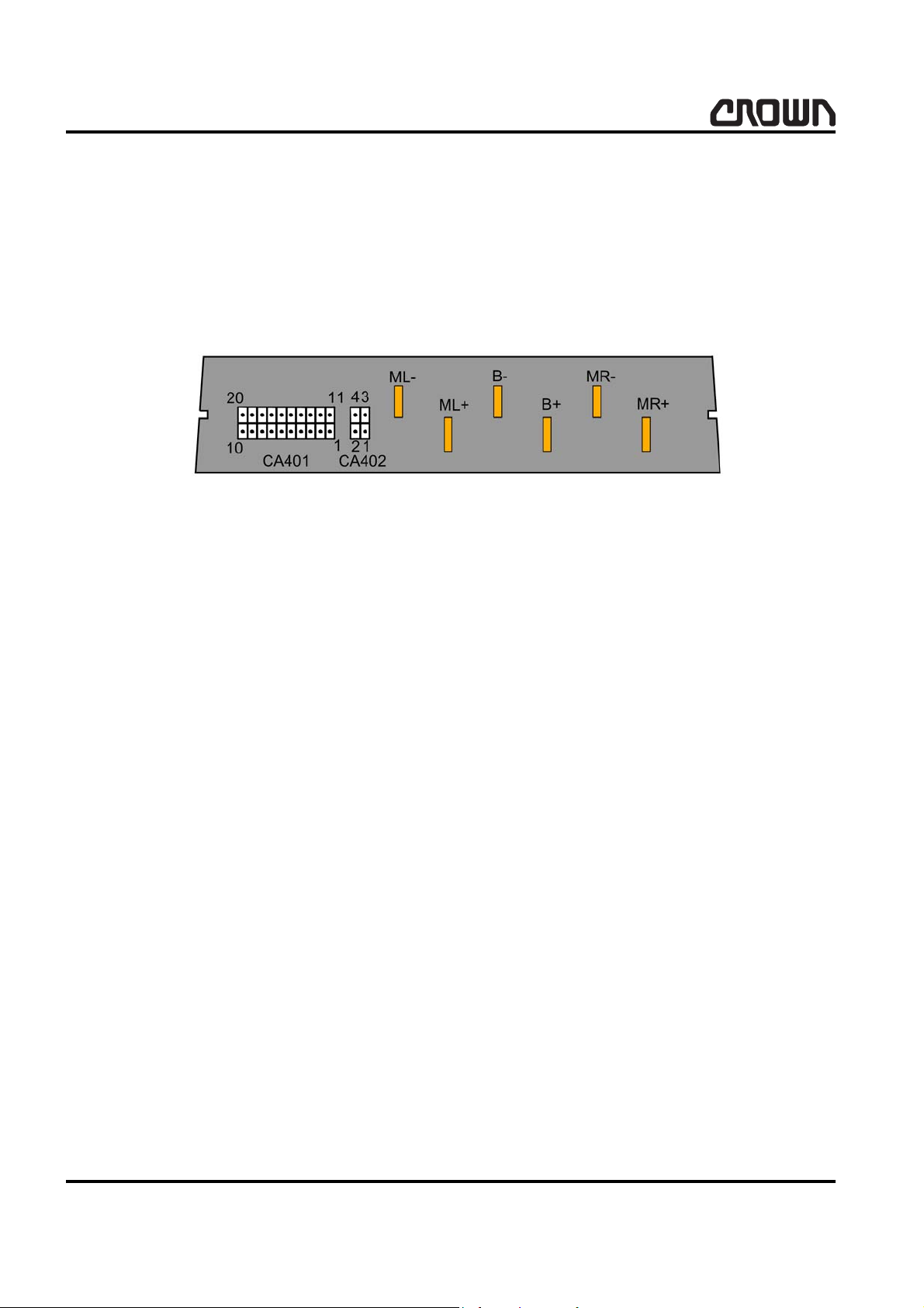
Capacitance
Capacitance voltage is present in the traction motor
controller. When performing maintenance which may
permit contact with the bus bars and associated power
cables, discharge the capacitors.
z Move truck to a secure non traffic maintenance
area with a level floor.
z Lockout or tagout truck as described in Battery -
Lockout/Tagout in this section.
z Place a minimum 100
B+ and B- terminals of the controller for three or
more seconds.
Ω, 2 W resistor between the
12033
MA-245015Printed in Germany
14
WAVE 50 10/2005 • Printed in Germany

INTRODUCTION

INTRODUCTION
Notice:
16
Printed in Germany
INTRODUCTION
This manual is intended for the service mechanic who
is seeking information about maintenance.
It contains a section on troubleshooting which will enable a qualified mechanic to locate and solve problems
which may occur.
Operator instructions
Information
This manual does not contain
operator instructions. Operator
instructions in booklet form are
sent with each vehicle.
Additional copies can be ordered if required. These
booklets are for you and your personnel to insure years
of safe, trouble free operation.
Service training
Complete Service Training is available to the mechanic
upon request.
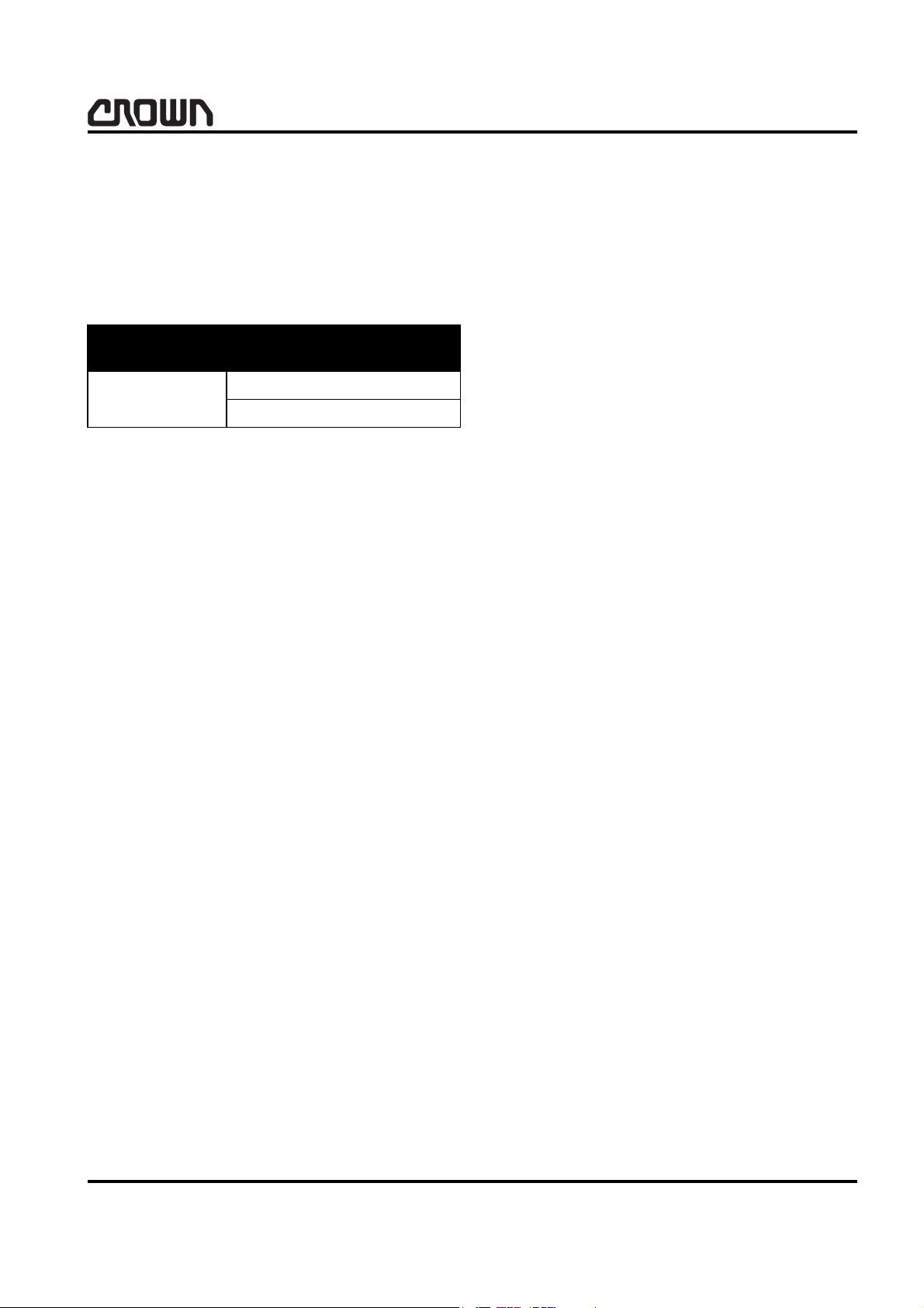
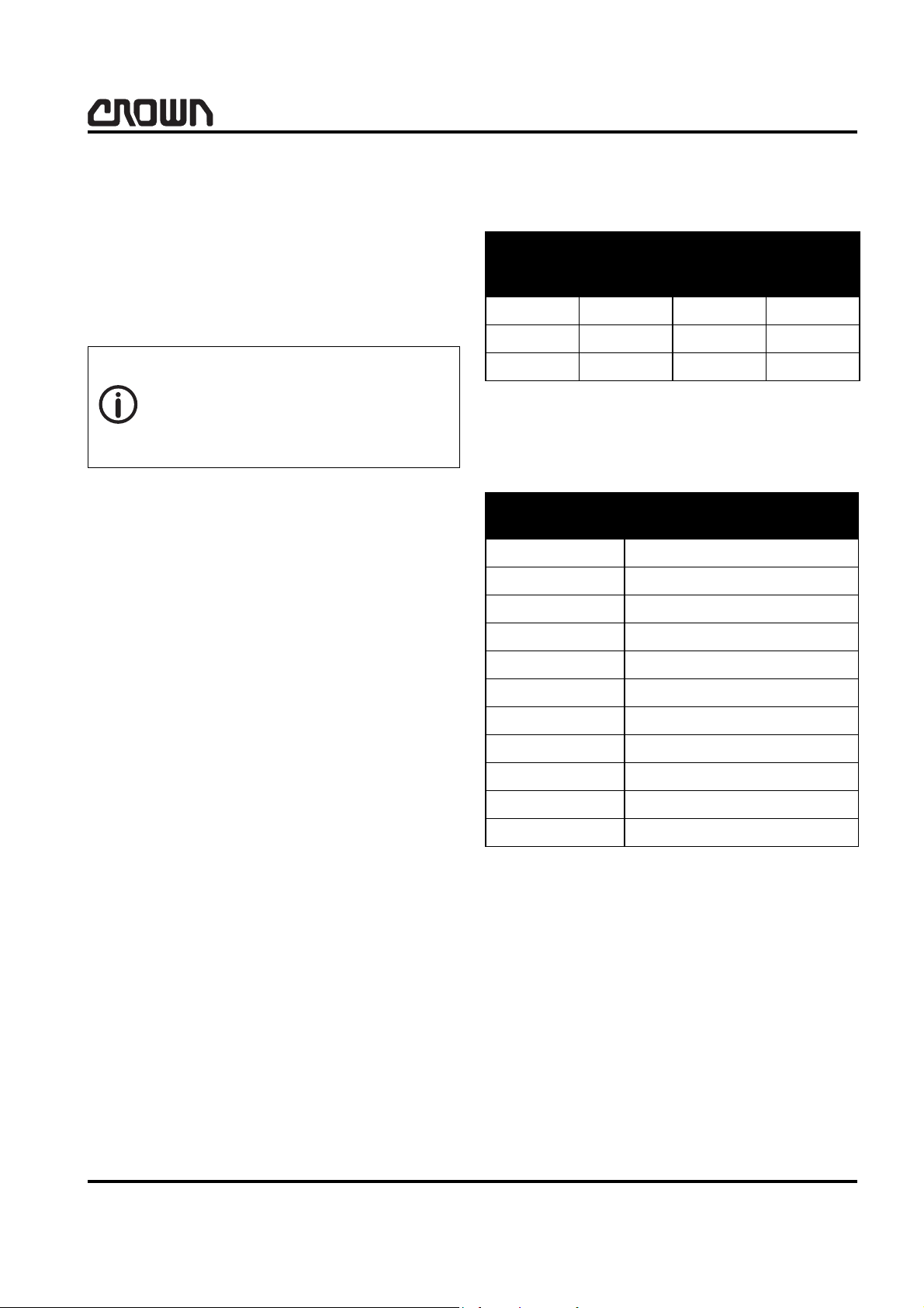
Choice of dash number depends on language. When
ordering, refer to chart below and complete the part
number the correct dash number
.
Dash
number
-001 German -004 Dutch
-002 French -005 Italian
-003 Spanish -006 English
This manual is arranged by major sections. The first
part of the Control Number, found in the footer of each
page, denotes the section in which a particular form will
be located. The section descriptions are as follows:
Section Description
M1 Lubrication and Adjustments
M2 Hydraulics
M3 Drive Unit
M4 Electrical
M5 Brake
Language Dash
number
Language
Publications
Copies of publications can be obtained from your
Crown Dealer:
Crown
Kronstadter Straße 11
81677 München,
Deutschland
Phone: (089) 930 02 – 0,
Fax: (089) 930 02 – 133, crown.com
or from
A Division of Crown Equipment Pty Ltd.
Long & Cooper Streets
Smithfield, N.S.W. 2164
Sydney, Australia
Phone: (61) 29 604 6000
Fax: (61) 29 609 2787
crown.com
M6 Not Used
M7 Mast
M8 Cylinder
M9 Platform
M10 Glossary
DIA Wiring Diagrams
WAVE 50 10/2005 • Printed in Germany
22450
02 Rev. 10/04
17
INTRODUCTION
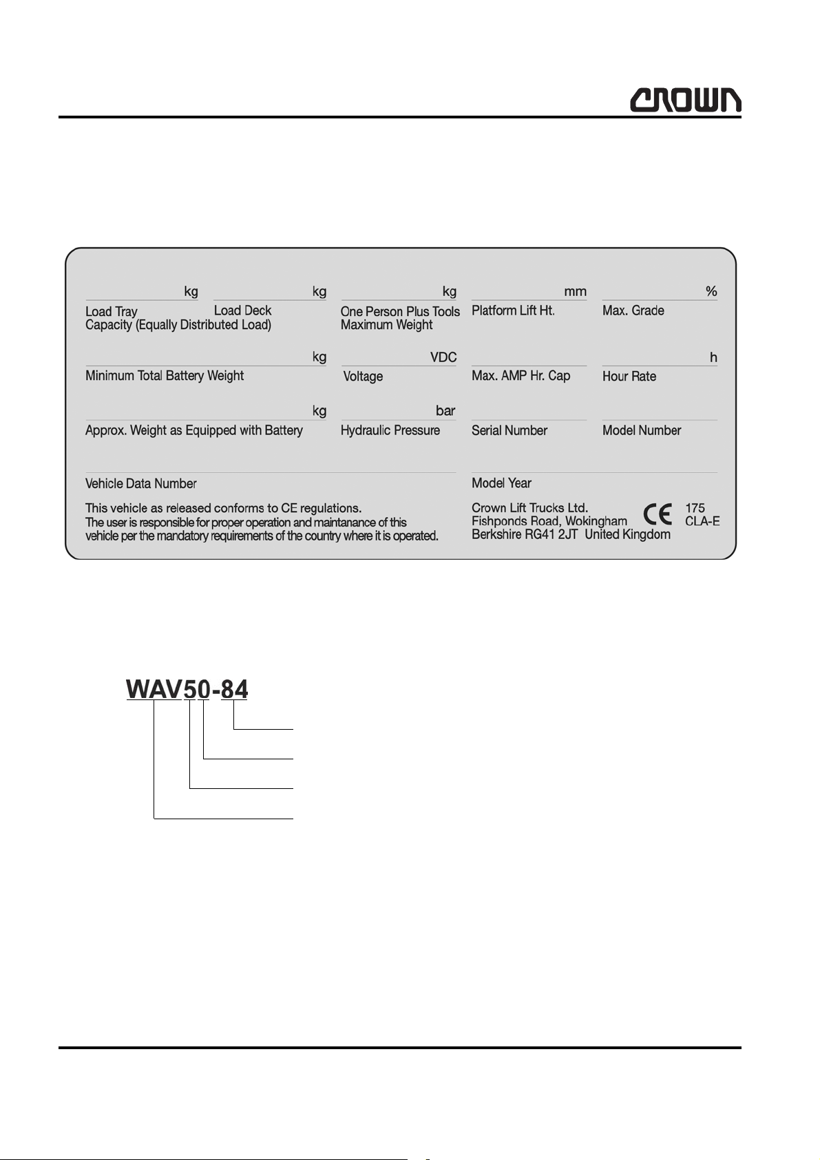
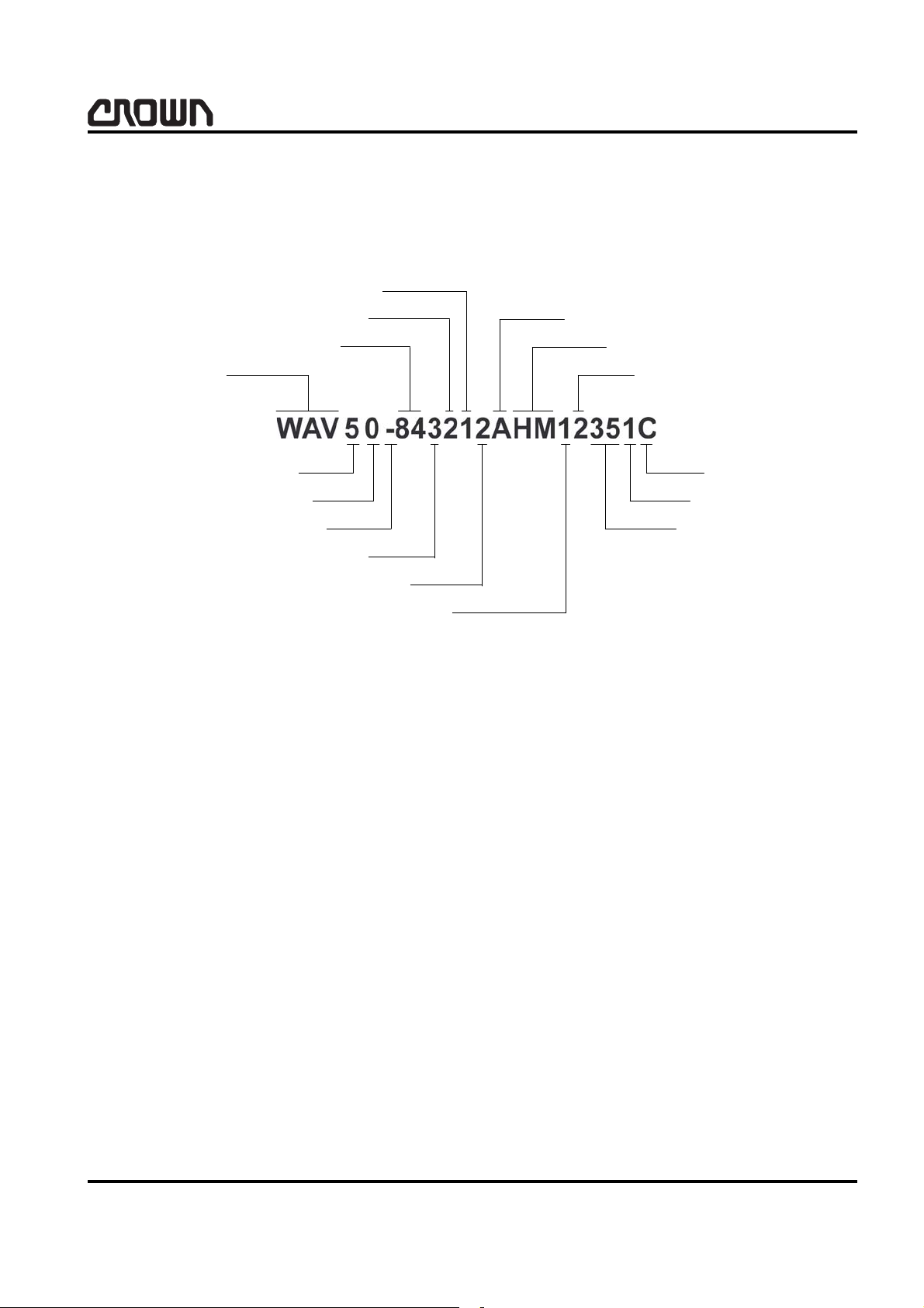
Data plate
The data plate is located on the lower rear section of
the third stage mast in the operator compartment and
includes a model number and a vehicle data number.
From these two numbers the vehicle model, series, series updates, vehicle size and specific vehicle data can
be determined. The following will explain the model
and vehicle data numbering system.
Model number example
MS-2450-006
6982-01
1 Image generator – Work Assist Vehicle
2 Series update: Significant change(s) to the product that
would not merit a new series number (generation)
3 Version: Characteristic that distinguishes vehicle from other
versions
4 Lift height: 2135 mm (84 in) or 2995 mm (118 in)
22450
18
WAVE 50 10/2005 • Printed in Germany
02 Rev. 10/04
INTRODUCTION
Vehicle data number example
The vehicle data number provides you and your dealer
with a wealth of information to ensure the selection of
proper parts for your vehicle.
You may simply provide this number to your dealer, or
use the following breakdown if selecting your own part
numbers or service information from this manual.
1 Work Assist Vehicle 9 Wheel Color
2 Issue 10 Alarms
3 Truck Version 11 Meter
4 Lift height 12 Strobe
5 Vehicle 13 Storage
6 Batteries 14 Aisle Guide
7 Battery Charger 15 System Controller
8 Color 16 Language Code
MS-2450-007
WAVE 50 10/2005 • Printed in Germany
22450
02 Rev. 10/04
19
INTRODUCTION
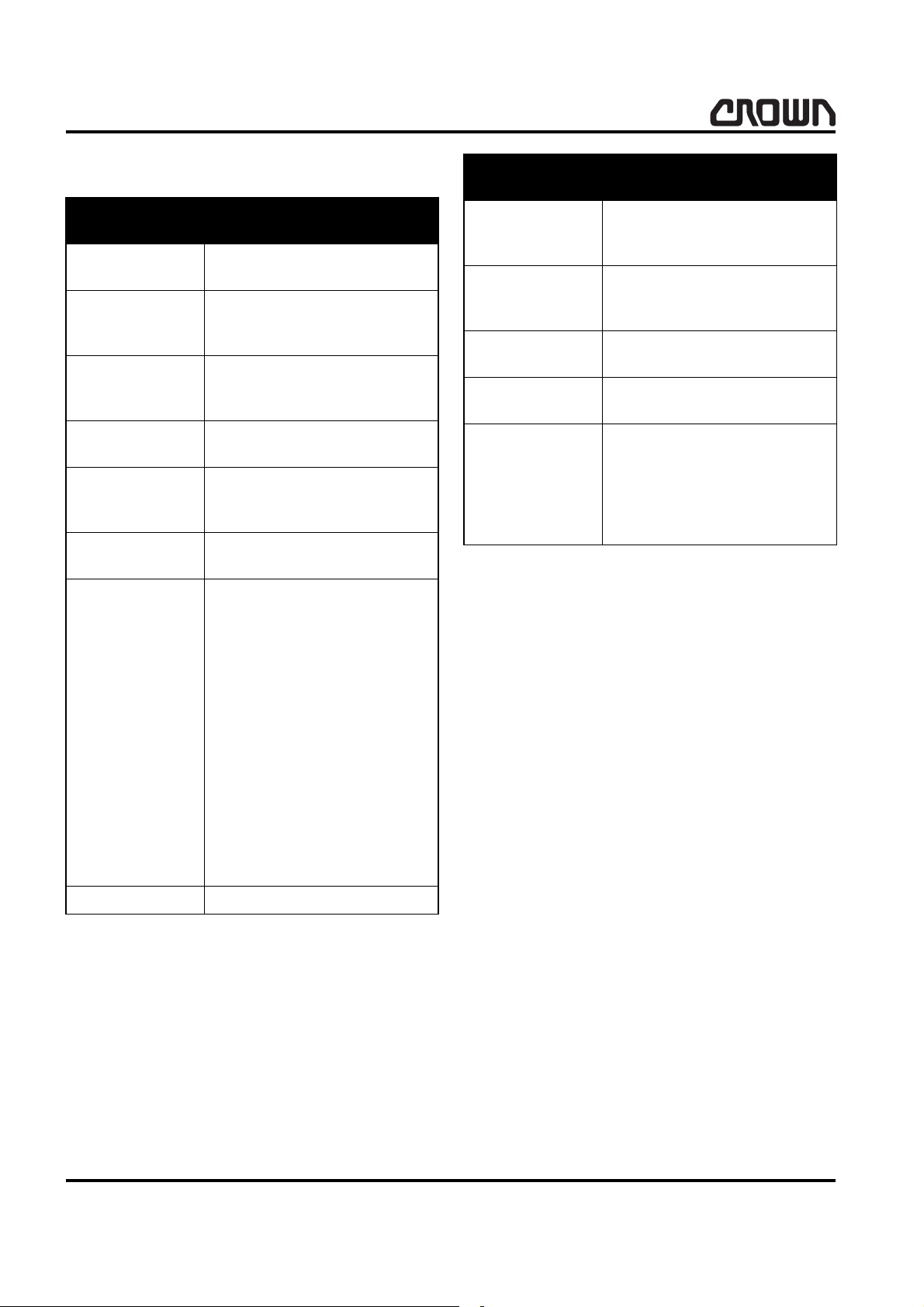
Data number information
Information Meaning
Information Meaning
Lift height
Vehicle
Batteries
Battery Charger
Color
Wheel Color
Alarm
84 = 2135mm (84 in)
118 = 2995mm (118 in)
– = Standard
C = Custom
S = Special
1 = Wet 160 A
2 = Wet 205
3 = Maintenance Free 195 A
1 = 15 A
2 = 25 A
1 = Maui Yellow
2 = Seafoam Green
3 = Alpine White
1 = Yellow
2 = Black
A = Forward
B = Reverse
C = Lift
D = Lower
E = Forward Reverse
F = Forward Lift
H = Forward Lower
I = Reverse Lift
J = Reverse Lower
K = Lift Lower
L = Forward Reverse Lift
M = Forward Reverse Lower
N = Reverse Lift Lower
O = Forward Lift Lower
P = Forward Reverse Lift, Lower
Q = None
Strobe
Storage
Aisle Guide
System Controller
Language code
– = No Strobe
1 = Strobe
– = No Storage
1 = One Pocket
2 = Two Pockets
-- = No Guidance
35 = Actual Width
– = No Handset
1 = Handset
A = French
B = German
C = British English
D = Spanish
E = Italian
F = Dutch
Meter HM = Hour Meter
22450
20
WAVE 50 10/2005 • Printed in Germany
02 Rev. 10/04

LUBRICATION & ADJUSTMENT
Printed in Germany
21

LUBRICATION & ADJUSTMENT
Notice:
22
Printed in Germany
 Loading...