

Page 1
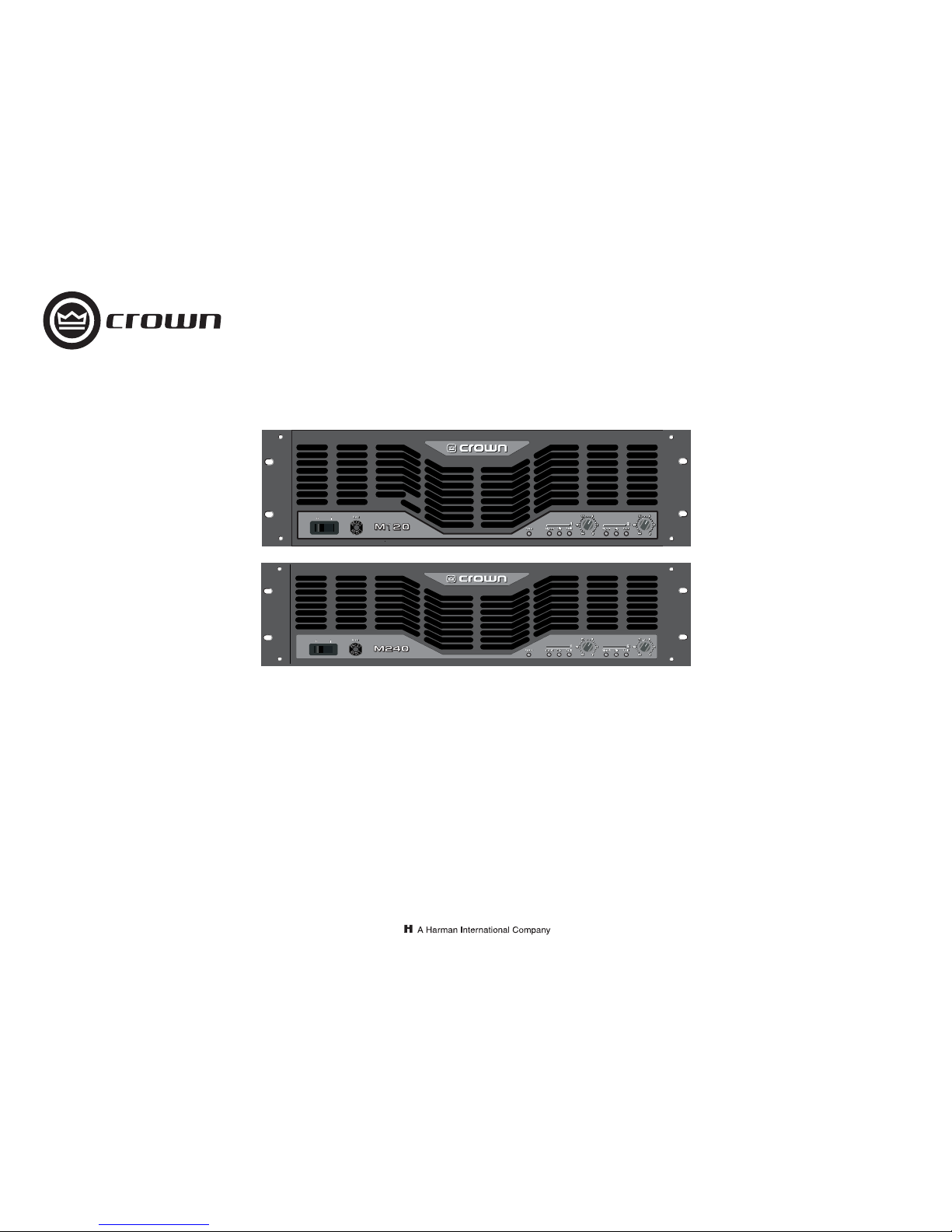
Operation Manual
M120
Obtaining Other Language Versions:
To obtain information in another language about the use of this product, please contact your
local Crown Distributor. If you need assistance locating your local distributor, please contact Crown at 574-294-8000.
This manual does not include all of the details of design, production, or variations of the equipment. Nor does it cover every possible
situation which may arise during installation, operation or maintenance.
The information provided in this manual was deemed accurate as of the publication date. However, updates to this information may have
occurred. To obtain the latest version of this manual, please visit the Crown website at www.crownaudio.com.
Trademark Notice:
Crown and Amcron are registered trademarks of Crown International. Other trademarks are the property of their
respective owners.
Some models may be exported under the name Amcron.
®
©2006 by Crown Audio® Inc., 1718 W. Mishawaka Rd., Elkhart, Indiana 46517-9439 U.S.A. Telephone: 574-294-8000
M Series
126781-5A
3/06
M240
1
1
Page 2
Operation Manual
M Series Power Amplifiers
page 2
1) Read these instructions.
2) Keep these instructions.
3) Heed all warnings.
4) Follow all instructions.
5) Do not use this apparatus near water.
6) Clean only with a dry clot h.
7) Do not block any ventilation openings. Install in accordance with the manufacturer’s instructions.
8) Do not install near any heat sources such as radiators,
heat registers, stoves, or other apparatus (including
amplifiers) that produce heat.
9) Do not defeat the safety purpose of the polarized or
grounding-type plug. A polarized plug has two blades
with one wider than the other. A grounding-type plug has
two blades and a third grounding prong. The wide blade
or the third prong is provided for your safety. If the provided plug does not fit into your outlet, consult an electrician for replacement of the obsolete outlet.
10) Protect the power cord from being wal ked on or pinched,
particularly at plugs, convenience receptacles, and the
point where they exit from the apparatus.
11) Only use attachments/accessories specified by the manufacturer.
12) Use only with a cart, stand, tripod, bracket, or table specified by the manufacturer, or sold with the apparatus.
When a cart is used, use caution when moving the cart/
apparatus combination to avoid injury from tip-over.
13) Unplug this apparatus during lightning storms or when
unused for long periods of time.
14) Refer all servicing to qualified service personnel. Servicing is required when the apparatu s has been damaged in
any way, such as power-supply cord or plug is damaged,
liquid has been spilled or objects have fallen into the
apparatus, the apparatus has been exposed to rain or
moisture, does not operate normally, or has been
dropped.
15) WARNING: TO REDUCE THE RISK OF FIRE OR ELECTRIC
SHOCK, DO NOT EXPOSE THIS APPARATUS TO RAIN
OR MOISTURE.
16) DO NOT EXPOSE TO DRIPPING OR SPLASHING. DO
NOT PLACE OBJECTS FILLED WITH LIQUID, SUCH AS
VASES,ON THIS APPARATUS.
TO PREVENT ELECTRIC SHOCK DO NOT REMOVE TOP OR
BOTTOM COVERS. NO USER SERVICEABL E PARTS INSIDE.
REFER SERVICING TO QUALIFIED SERVICE PERSONNEL.
À PRÉVENIR LE CHOC ÉLECTRIQUE N’ENLEVE Z PAS LES
COUVERCLES. IL N’Y A PAS DES PARTIES SERVICEABLE À
L’INTÉRIEUR. TOUS REPARATIONS DOIT ETRE FAIRE PAR
PERSONNEL QUALIFIÉ SEULMENT.
PARA PREVENIR UN CHOQUE ELÉCTRICO, NO RETIRE LAS
CUBIERTAS SUPERIOR O INFERIOR. NO EXISTEN PARTES
QUE PUEDAN SER REPARADAS POR EL USUARIO AL INTERIOR. REMITA EL SERVICICO AL PERSONAL TÉCHNICAL
CALIFICADO.
TO COMPLETELY DISCONNECT THIS EQUIPMENT FROM
THE AC MAINS, DISCONNECT THE POWER SUPPLY CORD
PLUG FROM THE AC RECEPTACLE. THE MAINS PLUG OF
THE POWER SUPPLY CORD SHALL REMAIN READILY
OPERABLE.
POUR DÉMONTER COMPLÈTEMENT L'ÉQUIPEMENT DE
L'ALIMENTATION GÉNÉRALE, DÉMONTER LE CÂBLE D'ALIMENTATION DE SON RÉCEPTACLE. LA PRISE D'ALIMENTATION RESTERA AISÉMENT FONCTIONNELLE.
PARA DESCONECTAR COMPLETAMENTE EL EQUIPO DEL
SUMINSTRO ELECTRICO, DESCONECTE EL CAB LE DE ALIMENTACION DE LA TOMA DE CA. LAS PATAS DEL CONECTOR DEL CABLE DE ALIMENTACIÓN DEBERAN
MANTENERSE EN BUEN ESTADO.
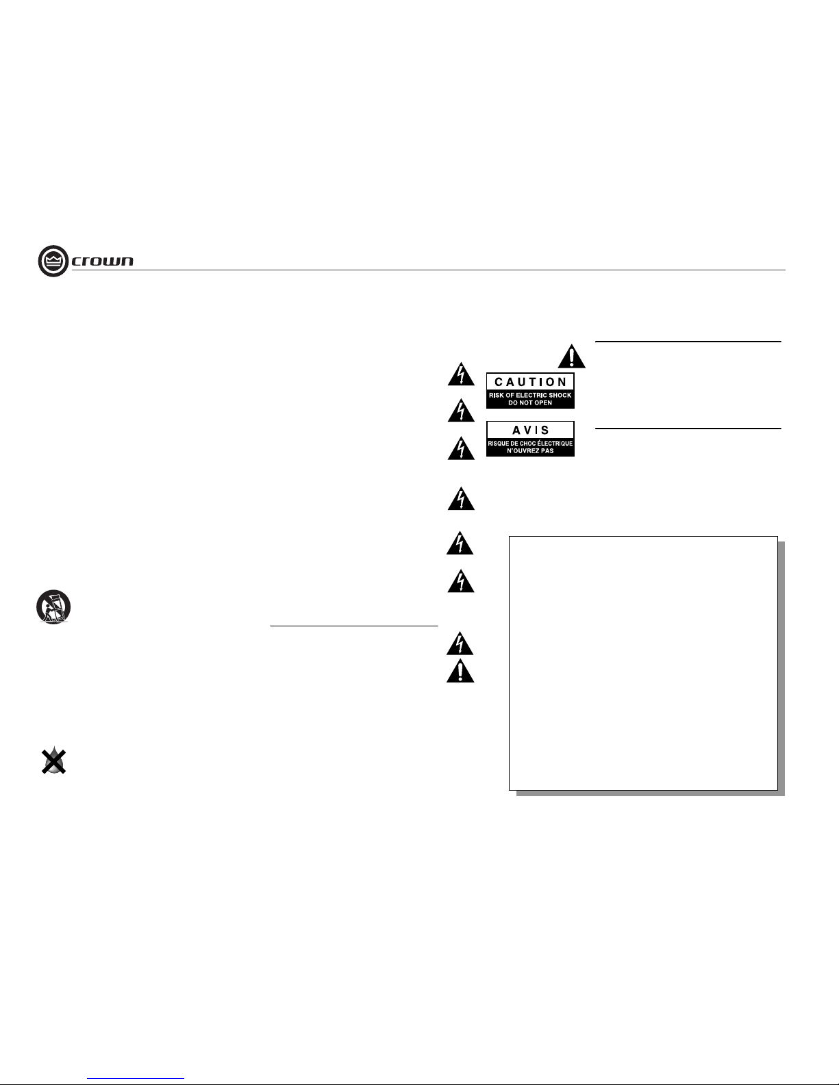
WATCH FOR THESE SYMBOLS:
The lightning bolt triangle is used to alert the user to the risk
of electric shock.
The exclamation point triangle is used to alert the user to
important operating or maintenance instructions.
REGARDEZ CES SYMBOLES
La triangle avec le sigle ‘’foudre’’ est employée pour alerter
l'utilisateur au risque de décharge électrique. Le triangle avec
un point d'exclamation est employée pour alerter l'utilisateur
d’instruction importantes pour lors opérations de maintenance.
ATENCION CON ESTOS SÍMBOLOS
El triángulo con el símbolo de rayo eléctrico es usado para
alertar al usuario de el riesgo de un choque eléctrico.
El triángulo con el signo de a dmiración es usado para alertar
al usuario de instrucciones imp ortantes de operación o mantenimiento.
Important Safety Instructions
FCC COMPLIANCE NOTICE
This device complies with part 15 of the FCC rules. Operation is subject to the following
two conditions: (1) This device may not cause harmful interference, and (2) this device
must accept any interference received, including interference that may caus e undesired
operation.
CAUTION: Changes or modifications not expressly approved by the party responsible for
compliance could void the user’s authority to operate the equipment.
NOTE: This equipment has been tested and found to comply with the limits for a Class B
digital device, pursuant to part 15 of the FCC Rules. These limits are designed to provide
reasonable protection against harmful interference in a residential installation. This
equipment generates, uses, and can radiate radio frequenc y energy and, if not installed
and used in accordance with the instruction manual, may cause harmful interfer ence to
radio communications. However, there is no guarantee that interference will not occur in a
particular installation. If this equipment does cause harmful interference to radio or television reception, which can be determined by turning the equipment off and on, the user is
encouraged to try to correct the interference by one or more of the following meas ures:
• Reorient or relocate the receiving antenna.
• Increase the separation between the equipment and receiver.
• Connect the equipment into an outlet on a circuit different from that to which the
receiver is connected.
• Consult the dealer or an experienced radio/TV technician for help.
IMPORTANT
M Series amplifiers require Class 2 output wiring.
Les amplificateurs de série de M exigent des câbles de sortie de
classe 2.
M-Reihe-Verstärker verlangen Klasse die 2 Produktionsverdrahtung.
Los amplificadores de la Serie M requieren de un cableado de salida Clase 2.
MAGNETIC FIELD
CAUTION! Do not locate sensitive high-gain equipment such as
preamplifiers or tape decks directly above or below the unit.
Because this amplifier has a high power density, it has a strong
magnetic field which can induce hum into unshielded devices that
are located nearby. The field is strongest just above and below the
unit.
If an equipment rack is used, we recommend locating the amplifier(s) in the bottom of the rack and the preamplifier or other sensitive equipment at the top.
Instrucciones de Seguridad Importantes
Importantes Instructions de Sécurité
Wichtige Sicherheitsinstruktionen
Page 3

page 3
M Series Power Amplifiers
Operation Manual
DECLARATION of CONFORMITY
Crown International, Inc.
Sue Whitfield
574-294-8289
[email protected]
European Representative's Name and Address:
Nick Owen
35, Bassets Field
Thornhill
Cardiff. South Glamorgen
CF14 9UG United Kingdom
Equipment Type: Commercial Audio Power Amplifiers
Family Name: CE
Model Names: M120, M240
EMC Standards:
EN 55103-1:1996 Electromagnetic Compatibility - Product Family Standard for Audio, Video, Audio-Visual and Entertainment Lighting Control Apparatus for Professional Use, Part 1: Emissions
EN 55103-1:1996 Magnetic Field Emissions-Annex A @ 10 cm and 1 M
EN 61000-3-2:1995+A14:2000 Limits for Harmonic Current Emissions (equipment input current ≤16A per phase)
EN 61000-3-3:1995 Limitation of Voltage Fluctuations and Flicker in Low-Voltage Supply Systems Rated Current ≤16A
EN 55022:1998 + A1: 2000 Limits and Methods of Measurement of Radio Disturbance Characteristics of ITE: Radiated, Class B Limits; Conducted, Class B
EN 55103-2:1996 Electromagnetic Compatibility - Product Family Standard for Audio, Video, Audio-Visual and Entertainment Lighting Control Apparatus for Professional Use, Part 2: Immunity
EN 61000-4-2:1995 Electrostatic Discharge Immunity (Environment E2-Criteria B, 4k V Contact, 8k V Air Discharge)
EN 61000-4-3:1996 Radiated, Radio-Frequency, Electromagnetic Immunity (Environment E2, criteria A)
EN 61000-4-4:1995 Electrical Fast Transient/Burst Immunity (Criteria B)
EN 61000-4-5:1995 Surge Immunity (Criteria B)
EN 61000-4-6:1996 Immunity to Conducted Disturbances Induced by Radio-Frequency Fields (Criteria A)
EN 61000-4-11:1994 Voltage Dips, Short Interruptions and Voltage Variation
Safety Standard:
EN 60065: 1998 Safety Requirements - Audio Video and Similar Electronic Apparatus
I certify that the product identified above conforms to the requirements of the EMC Council Directive 89/336/EEC as amended by 92/31/EEC, and the Low Voltage Directive 73/23/EES as amended by 93/68/EEC.
Larry Colburn Title: Senior Vice President of Marketing
Signed
Date of Issue: March 28, 2000
Issued By: Crown International, Inc.
1718 W. Mishawaka Road
Elkhart, Indiana 46517 U.S.A.
FOR COMPLIANCE QUESTIONS ONLY:
Page 4

Operation Manual
M Series Power Amplifiers
page 4
Important Safety Instructions .......................................................2
Declaration of Conformity ............................................................3
1 Welcome .................................................... 5
1.1 Features ...........................................................................5
1.2 How to Use This Manual ..................................................5
2 Setup ......................................................... 6
2.1 Unpack Your Amplifier ....................................................6
2.2 Install Your Amplifier ......................................................6
2.3 Ensure Proper Cooling ...................................................6
2.4 Choose Input Wire and Connectors ................................7
2.5 Choose Output Wire and Connectors ..............................7
2.6 Wire Your System ...........................................................8
2.6.1 Stereo Mode ..........................................................8
2.6.2 Bridge-Mono Mode ...............................................9
2.7 Connect to AC Mains ......................................................10
2.8 Startup Procedure ...........................................................10
3 Operation ...................................................11
3.1 Precautions .....................................................................11
3.2 Front Panel Controls and Indicators ............................... 13
3.3 Back Panel Controls and Connectors...............................13
4 Advanced Features and Options ......................... 14
4.1 Crown SST Modules ..................................................... 14
4.2 Fault Monitoring ............................................................ 14
4.3 Barrier Block Outputs .................................................... 15
4.4 Tamper-Resistant Hole Plugs ......................................... 15
4.5 Optional 0.775-V Input Sensitivity Setting ..................... 15
5 Principles of Operation .................................... 16
6 Troubleshooting ............................................18
7 Specifications .............................................. 19
8 Service . ....................................................21
8.1 International and Canada Service ...................................21
8.2 US Service ..................................................................... 21
8.2.1 Service at a US Service Center ............................. 21
8.2.2 Factory Service ..................................................... 21
8.2.3 Factory Service Shipping Instructions .................. 21
8.2.4 Packing Instructions.............................................. 21
8.2.5 Estimate Approval..................................................21
8.2.6 Payment of Non-Warranty Repairs......................... 21
9 Warranty ....................................................22
Crown Factory Service Information Form ...................................25
Table of Contents
Page 5
page 5
M Series Power Amplifiers
Operation Manual
1 Welcome
The M Series of power amplifiers from Crown®
represents a new era in affordable, quality
power amplification. The line consists of two
models in a uniform, rugged chassis, incorporating the best of tried-and-true design principles and innovative features.
Modern power amplifiers are sophisticated
pieces of engineering capable of producing
extremely high power levels. They must be
treated with respect and correctly installed if
they are to provide the many years of reliable
service for which they were designed.
In addition, M Series amplifiers include a number of features which require some explanation
before they can be used to their maximum
advantage.
Please take the time to study this manual so
that you can obtain the best possible service
from your amplifier.
1.1 Features
• Accurate, uncolored sound with very low distortion for the best in music and voice reproduction.
• Bridge-mono/stereo mode switch allows
your amplifiers/speakers to be set up in the
configuration that best suits your needs.
• Advanced protection circuitry guards against
shorted outputs, open circuits, DC, mismatched loads, general overheating, high-frequency overloads and internal faults.
• Extremely versatile, handling a wide range of
speaker impedances and outputs.
• Switchable input sensitivity.
• Proportional speed fan optimizes cooling
efficiency.
• Can be mounted in EIA standard 19-in. rack,
shallow 35.5-cm rack, or stacked on top of
each other.
• Features both standard 5-way binding posts
and genuine Neutrik
®
Speakon® output con-
nectors.
• Choice of 6.35-mm phone plug, XLR or barrier strip inputs. Optional SST crossovers may
provide other input connector options.
• Three Year, No-Fault, Fully Transferable Warranty completely protects your investment and
guarantees its specifications.
1.2 How to Use This Manual
This manual provides you with the necessary
information to safely and correctly setup and
operate your amplifier. It does not cover every
aspect of installation, setup or operation that
might occur under every condition. For additional information, please consult Crown’s
Amplifier Application Guide (available online at
www.crownaudio.com), Crown Technical Support, your system installer or retailer.
We strongly recommend you read all instructions, warnings and cautions contained in this
manual. Also, for your protection, please send
in your warranty registration card today. And
save your bill of sale — it’s your official proof
of purchase.
*
*
Page 6
Operation Manual
M Series Power Amplifiers
page 6
2.1 Unpack Your Amplifier
Please unpack and inspect your amplifier for
any damage that may have occurred during
transit. If damage is found, notify the transportation company immediately. Only you can initiate a claim for shipping damage. Crown will
be happy to help as needed. Save the shipping
carton as evidence of damage for the shipper’s
inspection.
We also recommend that you save all packing
materials so you will have them if you ever
need to transport the unit. Never ship the
unit without the factory pack.
YOU WILL NEED (not supplied):
• Input wiring cables
• Output wiring cables
Rack for mounting amplifier (or a stable surface
for stacking)
WARNING: Before you start to set up
your amplifier, make sure you read and
observe the Important Safety Instructions found at the beginning of this
manual.
2.2 Install Your Amplifier
CAUTION: Before you begin, make sure
your amplifier is disconnected from the
power source, with the power switch in
the “off” position and all level controls
turned completely down (counterclockwise).
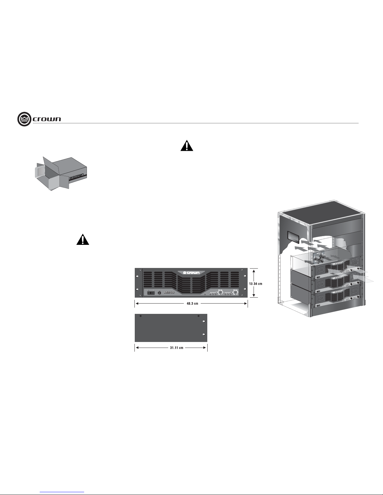
Use a standard 19-inch (48.3 cm) equipment
rack (EIA RS-310B). See Figure 2.1 for amplifier dimensions.
You may also stack amps without using a
cabinet.
NOTE: When transporting, amplifiers should be
supported at both front and back.
2.3 Ensure Proper Cooling
When using an equipment rack, mount units
directly on top of each other. Close any open
spaces in rack with blank panels. DO NOT
block front, rear or side air vents. The side
walls of the rack should be a minimum of two
inches (5.1 cm) away from the amplifier sides,
and the back of the rack should be a minimum
of four inches (10.2 cm) from the amplifier back
panel.
Figure 2.2 illustrates standard amplifier airflow.
2 Setup
Figure 2.2 Airflow
Figure 2.1
Dimensions
M240
M240
M240
M240
M240
M240
Page 7
page 7
M Series Power Amplifiers
Operation Manual
2.4 Choose Input Wire and Connectors
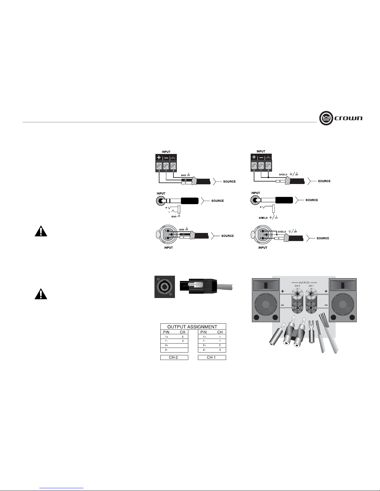
Crown recommends using pre-built or professionally wired, balanced line (two-conductor plus shield), 22-24 gauge cables and
connectors. Depending upon which amplifier input you choose,
you should use either 3-pin male XLR connectors, TRS phone
connectors, or terminal forks at the amplifier inputs.
Unbalanced line may also be used but may result in noise over
long cable runs.
Note: Amplifier input connectors not used for audio signal input
may be used for daisy-chaining of the audio signal to other components.
Figure 2.3 shows connector pin assignments for balanced wiring,
and Figure 2.4 shows connector pin assignments for unbalanced
wiring.
NOTE: Custom wiring should only be performed by
qualified personnel.
Figure 2.3
Balanced Input
Connector Wiring
Figure 2.4
Unbalanced Input
Connector Wiring
2 Setup
2.5 Choose Output Wire and Connectors
Crown recommends using pre-built or professionally wired, highquality, two- or four-conductor, heavy gauge speaker wire and
connectors. You may use two 4-pole Speakon
®
connectors (Figure 2.5 and Table 1) or banana plugs, spade lugs, or bare wire for
your output connectors (Figure 2.6). To prevent the possibility of
short-circuits, wrap or otherwise insulate exposed loudspeaker
cable connectors.
Note: Binding post outputs on European models come
with safety plugs installed to prevent European powercord plugs from being inserted. The top & bottom entry
positions for these connectors should therefore be used
with European models.
Using the guidelines below, select the appropriate size of wire
based on the distance from amplifier to speaker.
Distance Wire Size
up to 25 ft. 16 AWG
26-40 ft. 14 AWG
41-60 ft. 12 AWG
61-100 ft. 10 AWG
101-150 ft. 8 AWG
151-250 ft. 6 AWG
CAUTION: Never use shielded cable for output wiring.
Figure 2.6
5-Way Binding Post Connections
Figure 2.5
Left: Speakon
®
Output Connector on Back Panel
Right: Speakon
®
Cable Connector
Table 1 Speakon® Output Pin Assignments
Page 8

Operation Manual
M Series Power Amplifiers
page 8
2.6 Wire Your System
2.6.1 Stereo Mode
Typical input and output wiring is shown in
Figure 2.7.
INPUTS: Connect input wiring for both channels.
OUTPUTS: Maintain proper polarity (+/–) on
output connectors.
Connect Channel-1 loudspeaker’s positive (+)
lead to Channel-1 positive (red) terminal of amp;
repeat for negative (–). Repeat Channel 2 wiring
as for Channel 1.
How to Parallel the Inputs in Stereo Mode
There are three ways to feed the same signal to
each amplifier channel:
1. Buy a "Y" cable. Plug the female end into your
signal cable, and plug the split male ends into
both amplifier inputs.
2. Feed your signal to the Channel-1 input
(either barrier-block or Combo). Connect a
jumper wire (Figure 2.8) between the barrierblock Channel-1 (+) screw terminal and the
Channel-2 (+) screw terminal. Connect another
jumper wire between the Channel-1 (–) screw
terminal and the Channel-2 (–) screw terminal.
3. Feed your signal to the Channel-1 input screw
terminals. Using a mic cable or phone-to-phone
cable, connect Channel-1 Combo jack to Channel-2 Combo jack.
2 Setup
Figure 2.7
System Wiring, Stereo Mode
Figure 2.8 Jumper Positions to Parallel the Inputs
Page 9
page 9
M Series Power Amplifiers
Operation Manual
2.6.2 Bridge-Mono Mode
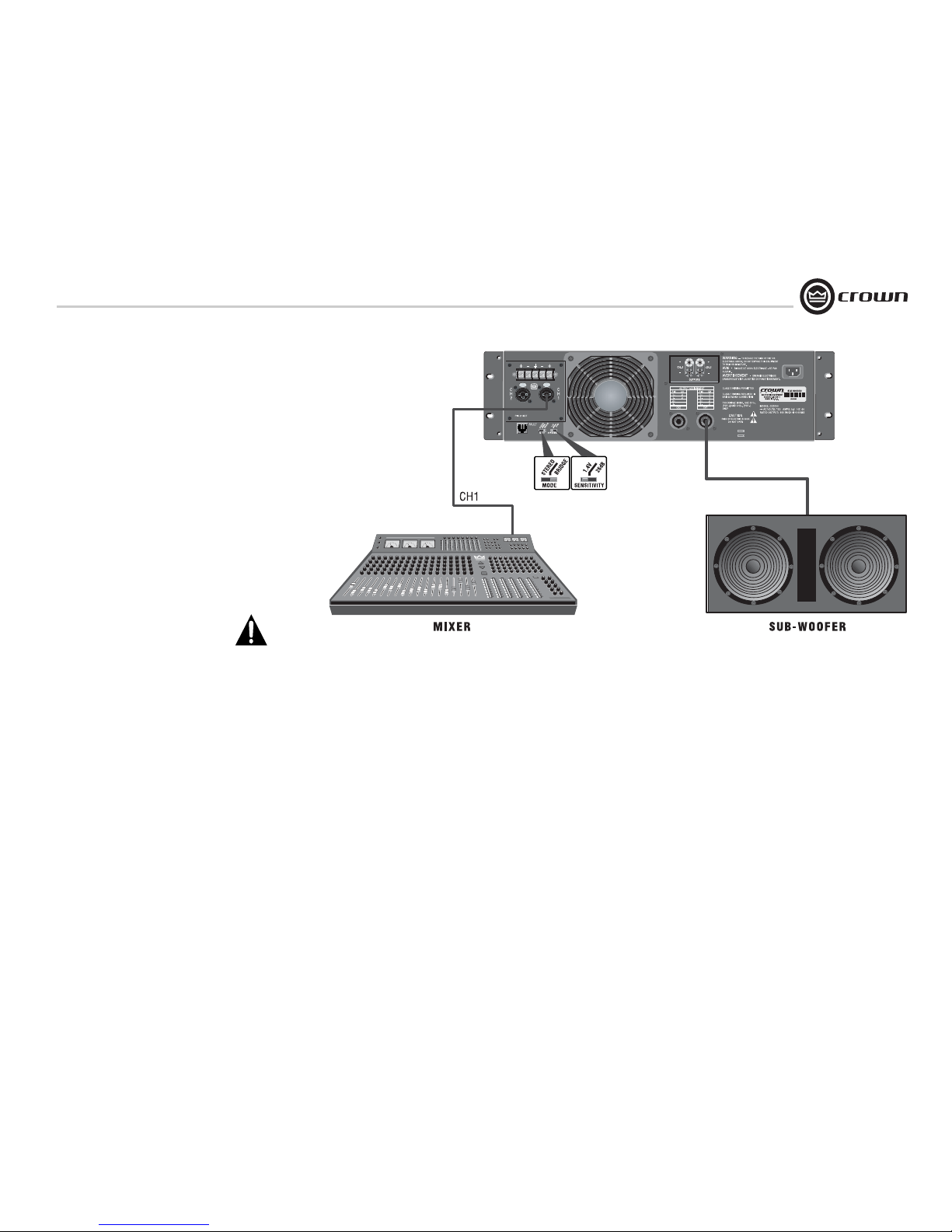
Typical input and output wiring is shown in
Figure 2.9.
Set the Mode Switch to Bridge.
INPUTS: Use only the Channel-1 input connector.
NOTE: Crown provides a reference of wiring pin
assignments for commonly used connector
types in the Crown Amplifier Application Guide
available at www.crownaudio.
OUTPUTS: If you are using the 5-way binding
posts, connect the speaker across the red binding post of each channel. Do not use the black
binding posts when the amp is being operated in
Bridge-Mono mode.
If you are using the Speakon
®
connectors, use
only the Channel 1 connector.
NOTE: The Channel 2 level control MUST
be turned down (full CCW) when operating the amplifier in Bridge-Mono mode.
Figure 2.9
System Wiring, Bridge-Mono Mode
2 Setup
Page 10

Operation Manual
M Series Power Amplifiers
page 10
2.7 Connect to AC Mains
Connect your amplifier to the AC mains power
source (power outlet) with the supplied AC power
cordset. First, connect the IEC end of the cordset to
the IEC connector on the amplifier; then, plug the
other end of the cordset to the AC mains.
WARNING: The third prong of this connector
(ground) is an important safety feature. Do
not attempt to disable this ground connection by using an adapter or other methods.
Amplifiers don’t create energy. The AC mains voltage and current must be sufficient to deliver the
power you expect. You must operate your amplifier
from an AC mains power source with not more than
a 10% variation above or a 15% variation below the
amplifier’s specified line voltage and within the
specfied frequency requirements (indicated on the
amplifier’s back panel label). If you are unsure of the
output voltage of your AC mains, please consult
your electrician.
2.8 Startup Procedure
Use the following procedure when first turning on
your amplifier:
1. Turn down the level of your audio source.
2. Turn down the level controls of the amplifier.
3. Turn on the “Power” switch. The Power indicator should glow.
4. Turn up the level of your audio source to an
optimum level.
5. Turn up the Level controls on the amplifier until
the desired loudness or power level is
achieved.
6. Turn down the level of your audio source to its
normal range.
If you ever need to make any wiring or installation
changes, don’t forget to disconnect the power cord.
For help with determining your system’s optimum
gain structure (signal levels) please refer to the
Crown Amplifier Application Guide, available online
at www.crownaudio.com.
2 Setup
Page 11

page 11
M Series Power Amplifiers
Operation Manual
3.1 Precautions
Your amplifier is protected from internal and external faults, but you should still take the following
precautions for optimum performance and safety:
1. Before use, your amplifier first must be configured for proper operation, including input and
output wiring hookup. Improper wiring can
result in serious operating difficulties. For
information on wiring and configuration, please
consult the Setup section of this manual or, for
advanced setup techniques, consult Crown’s
Amplifier Application Guide available online at
www.crownaudio.com.
2. Use care when making connections, selecting
signal sources and controlling the output level.
The load you save may be your own!
3. Do not short the ground lead of an output cable
to the input signal ground. This may form a
ground loop and cause oscillations.
3 Operation
4. WARNING: Never connect the output to
a power supply, battery or power main.
Electrical shock may result.
5. Tampering with the circuitry, or making unauthorized circuit changes may be hazardous and
invalidates all agency listings.
6. Do not operate the amplifier with the red Clip
LEDs constantly flashing.
7. Do not overdrive the mixer, which will cause
clipped signal to be sent to the amplifier. Such
signals will be reproduced with extreme accuracy, and loudspeaker damage may result.
8. Do not operate the amplifier with less than the
rated load impedance. Due to the amplifier’s
output protection, such a configuration may
result in premature clipping and speaker damage.
Remember: Crown is not liable for damage that
results from overdriving other system components.
Page 12
Operation Manual
M Series Power Amplifiers
page 12
Clip Fault
Signal
Clip Fault
Signal
Power
Power
1
1
2
2
Reset
Reset
I
Clip Fault
Signal
Clip Fault
Signal
WARNING
AVIS -
AVERTISSEMENT -
ó
RISQUE DE CHOC ELECTRIQUE - NE PAS
OUVRIR.
ENERGIE ELECTRIQUE
DANGEREUSE VIOR LA NOTICE DE FONCTIONNEMENT.
TO REDUCE THE RISK OF FIRE OR
ELECTRICAL SHOCK, DO NOT EXPOSE THIS EQUIPMENT
TO RAIN OR MOISTURE.
CAUTION
RISK OF ELECTRIC SHOCK
DO NOT OPEN
OUTPUT ASSIGNMENT
CH2
CH1
PIN
1+
12+
2-
PIN
1+
12+
2-
CH
2
2
CH
1
1
2
2
CLASS 2 WIRING PERMITTED
CLASS 1 WIRING REQUIRED IN
BRIDGE MONO CONNECTION
FOR BRIDGE MONO, USE CH1+,
(FOR +) AND CH2+, (FOR -)
ONLY
J. Fault Output
K. Stereo/
Bridge-Mono
Switch
L. Input
Sensitivity
Switch
A. Power Switch
B. Reset Switch
C. Power Indicator
D. Ch-1 Signal,
Clip& Fault
Indicators
D. Ch-2 Signal, Clip
& Fault Indicators
M. Neutrik Speakon
Outputs
®
I. IEC Power
Cord Connector
MODE
SENSITIVITY
S
T
E
R
E
O
1
.4
V
B
R
ID
G
E
2
6
d
B
E. Ch-1 Level Control E. Ch-2 Level Control
F. Barrier Block
Inputs
G. Neutrik Combo
(1/4-inch & XLR) Inputs
MODEL: M240
H. 5-way Binding Post
Output Connectors
3 Operation
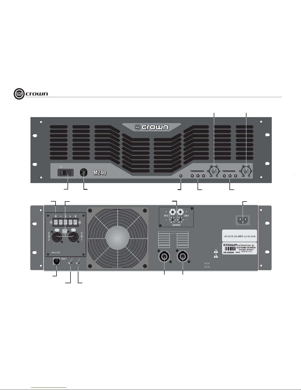
Figure 3.1 Front Panel and Back Panel Controls, Indicators and Connectors
Page 13

page 13
M Series Power Amplifiers
Operation Manual
3.2 Front Panel Controls
and Indicators
A. Power Switch
Switch turns the amplifier on (“
| ”) or off
(“ 0 ”).
B. Reset Switch
This front-panel pushbutton is used to
reset the circuit breaker that protects the
power supply.
C. Power Indicator
Green LED indicates amplifier has been
turned on and AC power is available.
D. Signal, Clip and Fault Indicators
Signal: A green LED for each channel
flashes when a low-level signal (≥ 40 dBm)
is present at the input.
Clip: A red LED for each channel turns on
when distortion becomes audible in the
amplifier output.
Fault: Normally off, this red indicator will
blink under fault conditions. See Section
6, Troubleshooting.
E. Level Controls: Detented rotary level
control for each channel.
3.3 Back Panel Controls
and Connectors
F. Barrier Block Inputs: May be wired balanced or unbalanced.
G. Neutrik
®
Combo Inputs: 1/4-inch
phone and XLR inputs. May be wired balanced or unbalanced.
H. 5-way Binding Post Outputs: One pair
per channel; accept banana plugs, spade lugs
or bare wire. Note: Binding post outputs on
European models come with safety plugs
installed to prevent European power-cord plugs
from being inserted. The side entry positions
for these connectors should therefore be used
with European models.
I. IEC Power Connector
J. Fault Output: RJ11 jack allows monitoring
of the amplifier’s Fault status from a remote
location. See Section 4.2.
K. Stereo/Bridge-Mono Switch: Two-position switch selects either Stereo or BridgeMono operation.
L. Input Sensitivity Switch: Two-position
switch selects either 1.4 V sensitivity or 26 dB
gain.
M. Neutrik
®
Speakon® Outputs: Two Neu-
trik Speakon NL3MP output connectors (mates
with NL4FC). See Figure 2.5 and Table 1 for
connector wiring.
3 Operation
Page 14
Operation Manual
M Series Power Amplifiers
page 14
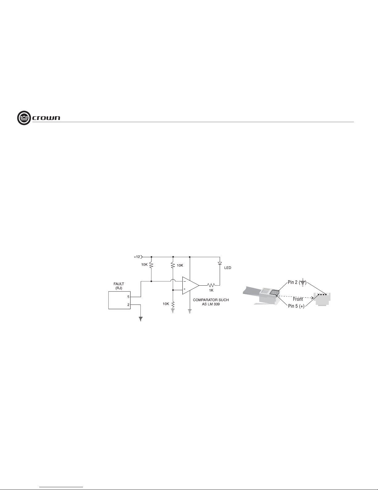
4.2 Fault Monitoring
The Fault (RJ-11) jack, which looks like a telephone plug, is located on the back of your MSeries amplifier. It gives you an easy way to
remotely monitor the amplifier’s fault status. To
set up a circuit that will cause an LED to light
whenever a fault status occurs, you can simply
use the suggested circuit shown in Figure 4.1.
When using this circuit, the LED will glow
whenever the amplifier is in one of four states: a
channel’s heatsink has reached its temperature
limit, the transformer has reached its temperature limit, the amplifier has just been turned on
and is in its turn-on-delay mode, or the amplifier is turned off.
If you choose to design your own circuit to
interface this signal to your system, note that
this RJ jack is polarity sensitive. Pin 2 must be
grounded, and Pin 5 must be supplied with a
positive voltage pull up (positive with respect
to ground). Refer to Figure 4.2 for RJ jack pin
assignments.
The mating connector for the M-Series RJ11
jack contains 4 contact pins in a 6-slot case, as
shown. For additional information please contact your local dealer or Crown Technical Support.
The maximum signal that can be exposed to the
fault jack is 35 VDC and 10 mA. Best results
are obtained with 10 mA LEDs.
Figure 4.1 Fault Status LED Circuitry
Figure 4.2 RJ Jack Wiring and Pin Assignments
4.1 Crown SST Modules
Crown optional SST (System Solution Topologies) modules were specially designed to
improve the versatility of your audio system.
They feature a variety of professional signal
routing and filtering capabilities, with active
crossovers that allow the audio signal to be
split and sent to auxiliary amplifiers. Your
amplifier may have come with an SST module
already factory-installed, or your choice of SST
modules can be easily added to the amplifier by
any authorized Crown Service Center.
For information on wiring and configuration of
amplifiers equipped with an optional Crown
SST crossover module, please refer to the SST
Crossover Reference Manual included in your
literature package.
For more information and for newer SST modules, see the Crown website at www.crownaudio.com.
4 Advanced Features
and Options
Page 15
page 15
M Series Power Amplifiers
Operation Manual
4 Advanced Features
and Options
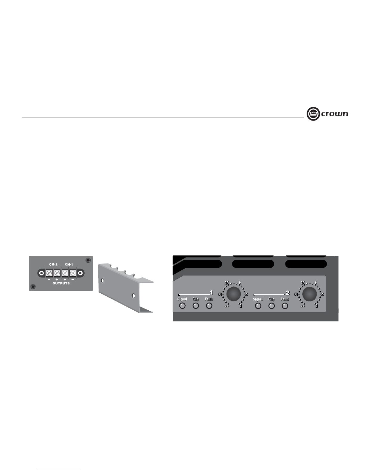
4.3 Optional Barrier Block Outputs
If you prefer, the 5-way binding post outputs on
your M-Series amplifier can be replaced with
model CEAS1 barrier block outputs (see Figure
4.3). You can order your M-Series amplifier
with barrier block outputs factory-installed on
new amplifiers or they can be added to existing
M-Series amplifiers by an authorized Crown
Service Center. Please contact Crown Technical
Support or your local Crown Service Center for
more information on this option.
4.4 Tamper-Resistant Hole Plugs
Your M-Series amplifier comes with a set of
tamper-resistant hole plugs, which allow you to
“protect” the level controls against unauthorized adjustment. To use, simply pull off the
control knobs from the front of the amp, and
slip the hole plugs into place (see Figure 4.4).
The plugs should slide easily into position,
without forcing. Once in place, the plugs will
help to avoid most accidental or intentional
tampering (some situations may require additional security measures).
To remove the hole plugs, simply pry the plug
away from the amplifier case using a small, flatblade screwdriver. To help to ensure adequate
security, the plugs have been designed to be
more difficult to remove than to place into position. If necessary, additional hole plugs can be
purchased separately from Crown’s Parts
Department (Part # 103234-1).
Store your knobs in a safe location should you
need to make level adjustments in the future.
4.5 Optional 0.775-V Input Sensitivity Setting
The M-Series amplifier also provides an
optional 0.775-V input sensitivity setting. If you
determine your application requires this sensitivity setting, please contact Crown Technical
Support for more information.
Figure 4.3 Model CEAS1 Barrier Block Ouput Connectors
Figure 4.4 Tamper-Resistant Hole Plugs Installed in an M-Series Amplifier
Page 16
Operation Manual
M Series Power Amplifiers
page 16
5 Principles of Operation
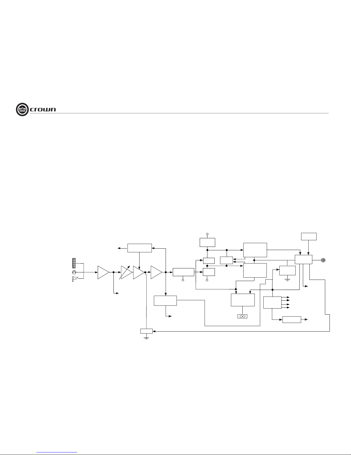
For the sake of simplicity, only channel one of
the amplifier is described.
Signal is presented to the M120 and M240
through one of three connectors when using
the standard input module. Each channel is
outfitted with a balanced XLR / phone jack, and
a barrier strip. These connectors are wired in
parallel, which allows daisy chaining when
needed. The signal is then converted from balanced to unbalanced in the Balanced Input
Stage where it also receives RFI protection.
Signal then flows into the Variable Gain Stage
where the front panel level controls are allowed
to affect the gain.
Following this stage, the signal is put under the
control of a full-time compressor circuit comprised of a symmetrical window detector, a
buffer amplifier, and the gating op amp which
uses several small components to set the compressor’s attack and decay characteristics. The
actual compressing is accomplished by an
opto-isolator which affects the gain in the signal path.
The signal next enters the main amplifier error
amp where it is mixed with a small portion of
the output signal in such a way as to control the
amplifier’s overall output performance.
Following the error amp is the LVA stage, which
is where the low-voltage referenced signal gets
translated to the output high-voltage rails. The
last voltage amplifier, in conjunction with a
bootstrapped current source, drives both predrivers and the bias servo. The bias servo is
mounted in such a way as to translate the output heatsink temperature into a controlled bias
current to prevent thermal runaway and hold
the amplifier’s notch distortion to a minimum.
The predrivers provide enough signal to activate the drivers, which together operate in the
class AB range. For the major output current
requirements, the drivers feed the various numbers of paralleled output transistors which
operate in a class B mode. This we call the Triple-Deep Darlington Output Stages.
TRANSLATOR LVA
BIAS
CURRENT
SOURCE
BALANCE
INPUT STAGE
VARIABLE
GAIN STAGE
ERROR
AMP
BALANCED
INPUTS
TO SIGNAL
PRESENCE
INDICATOR
COMPRESSOR
CONTROL
TO CLIP
INDICATOR
BUFFER
MUTE
DC PROTECT
LOGIC
TO
FAULT
CONNECTOR
–VCC
–VCC
+ HI-VOLTAGE
BOOTSTRAP
BIASBIASBIASBIASBIAS
TDVI
LIMITER
TRIPLE-DEEP
DARLINGTON
NPN POSITIVE
OUTPUT STAGE
TRIPLE-DEEP
DARLINGTON
NPN NEGATIVE
OUTPUT STAGE
PROPORTIONAL
SPEED
FAN
CONTROL
FAN
DC
PROTECT
HEATSINK
TEMPERATURE
OUTPUT
CONTROL
HEATSINK
TEMPERATURE
TRANSFORMER
TEMPERATURE
TO FAULT
INDICATOR
POWER
SUPPLY
+ VCC
+ 15V
– 15V
– VCC
TURN-ON
DELAY
+
OUTPUT
BOOTSTRAP
CIRCUIT
+ HI-VOLTAGE
BOOTSTRAP
Figure 5.1
M-Series Amplifier
Block Diagram
(Shown with Standard Input Module)
Page 17

page 17
M Series Power Amplifiers
Operation Manual
The output transistors are protected by the Time
Dependent Voltage & Current circuit. This circuit protects the devices from extending
beyond their safe area of operation, but allows
the devices to provide high bursts of peak
power with music, allowing your amplifier to
deliver more punch. When all is said and done,
this amplifier output topology offers a good
combination of low quiescent amplifier heating,
great distortion performance at high powers,
and relative simplicity, with impressive reliability and value.
For extended flexibility, all of the amplifier’s
output power is delivered through the Channel
1 Neutrik
®
Speakon® connector. Both Channel
1 and 2 output terminals are wired through the
Channel 1 connector, allowing dual or bridge
mono applications to be available with one
speaker cable. Refer to Figure 2.3 and Table 1
for Neutrik
®
Speakon® output pin assign-
ments.
The output relay, in conjunction with input signal mute circuit, assures the amplifier will be
well-behaved during turn on and off. In the
event of an amplifier output failure, a triac will
activate to turn off the offending channel and
protect your speakers.
The turn on delay circuit functions to keep the
output relay open until all the voltages are up
and stable, both in the amplifier, and in all the
components in the system ahead of the amplifier.
Heatsink temperature is monitored by a thermal
probe attached to the heatsink. As the temperature rises, the probe sends a proportional current to the proportional speed fan circuit which
starts the fan. Should the power transformer
reach its maximum safe temperature, an internal thermal switch opens and the fan circuit
turns on full speed to quickly cool down the
amplifier. It also disconnects the load via the
output relay, removing any output current and
further speeding a cool-down cycle. Extra care
was taken during the design stage to set this
point both to protect your investment and to
guard against nuisance tripping.
Whenever the heatsinks or the transformer
reach a maximum temperature, or during the
normal turn on delay window, the front panel
Fault LEDs will blink to get your attention.
A modular RJ-11 jack is mounted on the back
panel (similar to the type used on telephones).
Pins 2 and 5 are connected to an opto-isolator
which is always in a low-resistance state whenever the unit is on and happy. Should a fault be
detected or should the amplifier lose AC power,
the opto-isolator will change to a high resistance, allowing the user
to remotely detect the status of the amplifier.
The Signal Presence Indicators tap the signal
chain just before the level controls and prior to
the power amplifier chain. They are not amplifier output indicators and should only be used
to indicate the presence of signal to the amplifier front end.
The Clip light is driven from the output of the
compressor circuitry and lights to indicate the
onset of audible distortion. The Power LED is
driven from the low-voltage supply.
A positive and negative regulator form the ±15volt power supplies. Add to that the main transformer, a full-wave bridge rectifier, and high
energy electrolytics to form the main power
supply. They are protected by the front-panel
line circuit breaker and controlled by the frontpanel power switch.
5 Principles of Operation
Page 18
Operation Manual
M Series Power Amplifiers
page 18
6 Troubleshooting
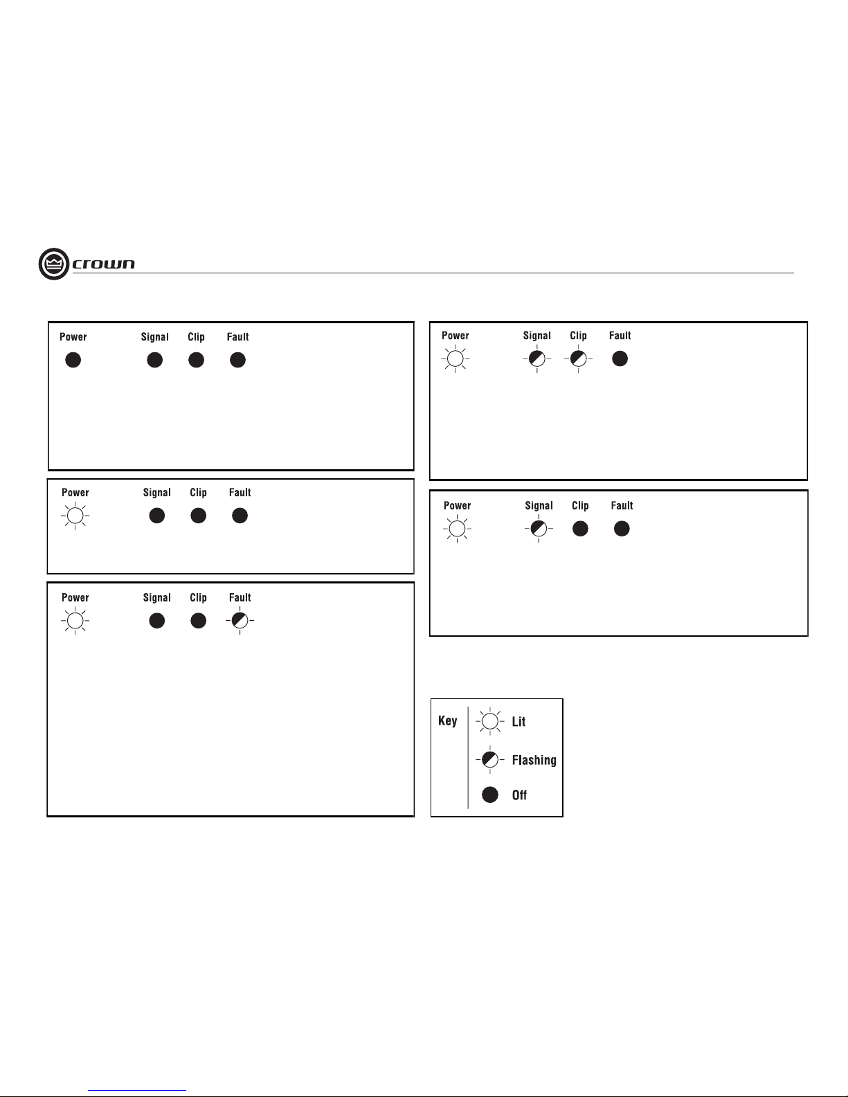
CONDITION: Power indicator is
off.
POSSIBLE REASON
• The amplifier has lost AC power.
• The amplifier’s Power switch is off.
• The amplifier’s power cord is not plugged
in at either end.
The amplifier’s circuit breaker has tripped.
Allow the amplifier to cool; remove excessive
loads, and press the reset switch on the front
panel.
CONDITION: No input signal (Signal
indicator is not flashing even though audio is
applied).
POSSIBLE REASON:
• Input signal level is very low.
• Master audio from mixer turned down.
• Input cable broken or not plugged in.
CONDITION: Fault indicator is
flashing.
POSSIBLE REASON:
• The amplifier has just been turned on and
is still in the 4-second turn-on delay.
• The heatsinks are too hot.
• The transformer thermal protection is
activated.
• The amplifier output wires have developed a short circuit.
• The amplifier output stage has stopped
operating. Refer the unit to an authorized
Crown Service Center.
The fault status of the amplifier can also be
monitored remotely by attaching a signal
device to the Fault jack located on the amplifier back panel. See the Advanced Features
and Options section for more detail.
CONDITION: Distorted sound.
POSSIBLE REASON:
• Load is wired incorrectly or Stereo/Mono mode
switch is set incorrectly. Check both.
• Input signal level is too high. Turn down your
amplifier level controls, or turn down the input
signal, until the clip LED goes out.
Note: If sound is distorted but clip LED is not flashing, check mixer levels and gain staging, mixer clip
lights, and pads built into microphones.
CONDITION: Input signal but no sound.
POSSIBLE REASON:
• Speakers not connected. Make sure the Neutrik
NL4 connector is fully seated and locked.
The amplifier output level is so high that the breaker
has tripped. Try to identify and correct the problem
before resetting the breakers. If the problem persists,
refer the unit to an authorized Crown Service Center.
Page 19
page 19
M Series Power Amplifiers
Operation Manual
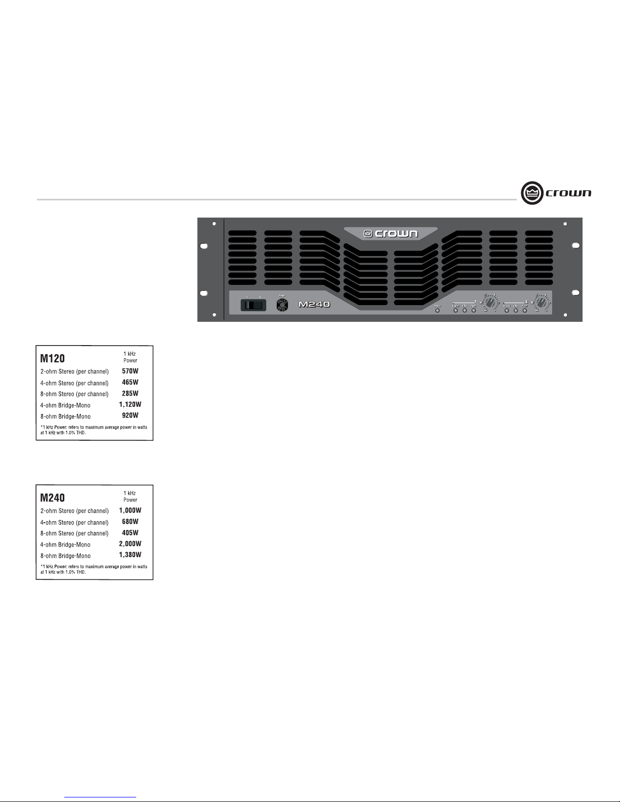
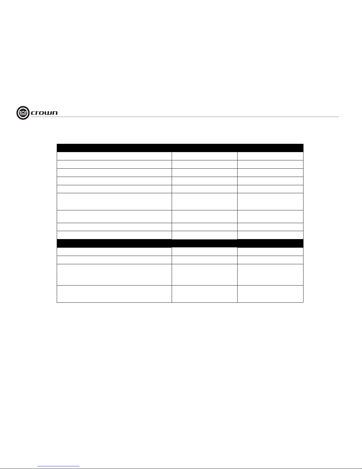
Minimum Guaranteed Power M120 M240
1 kHz with 0.5% THD
Stereo, 2 ohms (per ch.)
Stereo, 4 ohms (per ch.)
Stereo, 8 ohms (per ch.)
Bridge mono, 4 ohms
Bridge mono, 8 ohms
570W
465W
285W
1,120W
920W
1,000W
680W
405W
2,000W
1,380W
Performance M120 M240
Sensitivity (volts RMS) for full rated power at 8 ohms 1.4 V, switchable to 26 dB gain 1.4 V, switchable to 26 dB gain
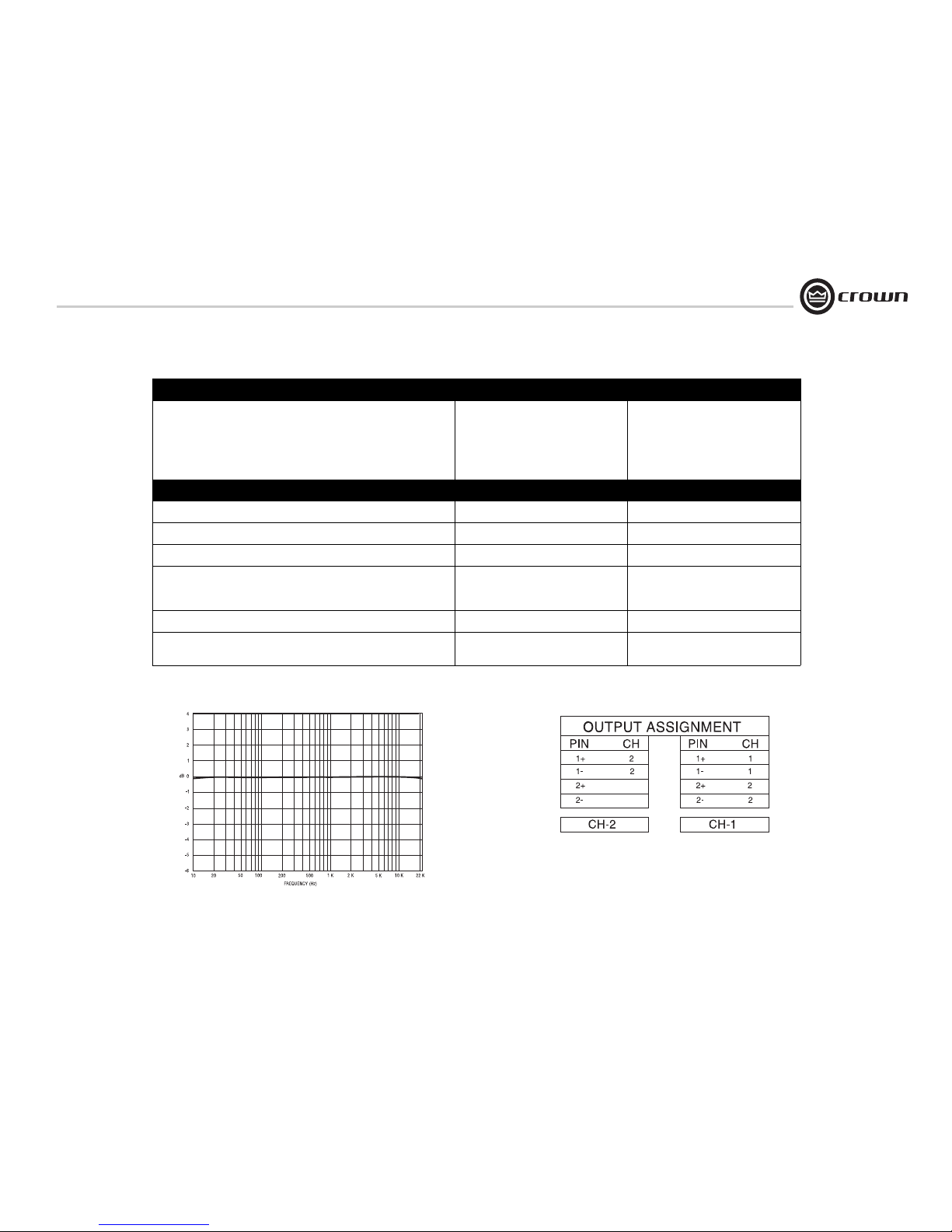
Frequency Response (at 1 watt, 20Hz - 25 kHz) ± 0.2 dB ± 0.2 dB
Phase Response (at 1 watt , 20Hz to 20 kHz) ±15° ±15°
Signal to Noise Ratio below rated 1 kH power
A-weighted
20Hz to 20kHz
> 105 dB
> 100 dB
> 105 dB
> 100 dB
Total Harmonic Distortion (THD) at 1 full bandwidth power, from 20 Hz to 20 kHz < 1.0% < 1.0%
Intermodulation Distortion (IMD) 60 Hz and 7 kHz at 4:1,
from full rated output to –35 dB
< 0.1% < 0.1%
7 Specifications
Figure 7.1 Typical Frequency (Amplitude) Response
Figure 7.2 Output Pin Assignments
Page 20
Operation Manual
M Series Power Amplifiers
page 20
Performance M120 M240
Damping Factor (8 ohm): 10 Hz to 400 Hz > 400 > 400
Crosstalk (below rated power, 20 Hz to 20 kHz) > 55 dB > 55 dB
Common Mode Rejection (CMR)(20 Hz to 1 kHz) > 70 dB > 70 dB
DC Output Offset (Shorted input) ± 10 mV ± 10 mV
Input Impedance (nominally balanced, nominally unbalanced) 20 kilohms, 10 kilohms 20 kilohms, 10 kilohms
Load Impedance (Note: Safe with all types of loads)
Stereo
Bridge Mono
2-8 ohms
4-8 ohms
2-8 ohms
4-8 ohms
Voltage Gain (at maximum level setting) 30.5-dB gain at 1.4-volt sensitivity
26-dB gain at 2.34-volt sensitivity
32.1-dB gain at 1.4-volt sensitivity
26-dB gain at 2.83-volt sensitivity
AC Line Voltage and Frequency Configurations Available (± 10%) 230/240 VAC and 50/60 Hz 230/240 VAC and 50/60 Hz
AC Line Current (both amplifiers draw no more than 90 watts at idle) 3.5 A 5.0
Construction M120 M240
Ventilation Flow-through ventilation from front to back Flow-through ventilation from front to back
Cooling Proportional speed fan Proportional speed fan
Dimensions EIA Standard 19-inch rack mount width (EIA
RS-310B), 5.25-inch (13.34-cm) height and
12.25-inch (31.11-cm) depth behind front
mounting surface
EIA Standard 19-inch rack mount width (EIA
RS-310B), 5.25-inch (13.34-cm) height and
12.25-inch (31.11-cm) depth behind front
mounting surface
Weight
Net
Shipping
32.6 pounds (14.79 kg)
38.6 pounds (17.49 kg)
40.3 pounds (18.28 kg)
46.3 pounds (20.98 kg)
7 Specifications
Page 21

page 21
M Series Power Amplifiers
Operation Manual
Crown amplifiers are quality units that rarely require servicing. Before returning your unit for service, please contact Crown Technical Support to verify the need for
servicing.
This unit has very sophisticated circuitry which should
only be serviced by a fully trained technician. This is one
reason why each unit bears the following label:
CAUTION: To prevent electric shock, do not
remove covers. No user serviceable parts
inside. Refer servicing to a qualified technician.
Complete the Crown Audio Factory Service Information
form, in the back of this manual, when returning a Crown
product to the factory or authorized service center. The
form must be included with your product inside the box
or in a packing slip envelope securely attached to the
outside of the shipping carton. Do not send this form
separately.
8.1 International and Canada Service
Service may be obtained from an authorized service center. (Contact your local Crown/Amcron representative or
our office for a list of authorized service centers.) To
obtain service, simply present the bill of sale as proof of
purchase along with the defective unit to an authorized
service center. They will handle the necessary paperwork
and repair.
Remember to transport your unit in the original factory
pack.
8.2 US Service
Service may be obtained in one of two ways: from an
authorized service center or from the factory. You may
choose either. It is important that you have your copy of
the bill of sale as your proof of purchase.
8.2.1 Service at a US Service Center
This method usually saves the most time and effort. Simply present your bill of sale along with the defective unit
to an authorized service center to obtain service. They
will handle the necessary paperwork and repair. Remember to transport the unit in the original factory pack. A list
of authorized service centers in your area can be obtained
from Crown Factory Service, or online from
http://www.crownaudio.com/support/servcent.htm.
8.2.2 Factory Service
Crown accepts no responsibility for non-serviceable
product that is sent to us for factory repair. It is the
owner’s responsibility to ensure that their product is serviceable prior to sending it to the factory. Serviceable
product list is available at
http://crownweb.crownintl.com/crownrma/.
For more information, please contact us direct.
A Service Return Authorization (SRA) is required for
product being sent to the factory for repair. An SRA can
be completed online at www.crownaudio.com/support/
factserv.htm. If you do not have access to the web, please
call Crown’s Customer Service at 574.294.8200 or
800.342.6939 extension 8205.
For warranty service, we will pay for ground shipping
both ways in the United States. Contact Crown Customer
Service to obtain prepaid shipping labels prior to sending the unit. Or, if you prefer, you may prepay the cost of
shipping, and Crown will reimburse you. Send copies of
the shipping receipts to Crown to receive reimbursement.
Your repaired unit will be returned via UPS ground.
Please contact us if other arrangements are required.
8.2.3 Factory Service Shipping Instructions:
1. Ser vice Return Authorization (SRA) is required for
product being sent to the factory for service. Please
complete the SRA by going to
www.crownaudio.com/support/factserv.htm. If you
do not have access to our website, call
1.800.342.6939, extension 8205 and we'll create the
SRA for you.
2. See packing instructions that follow.
3. Ship product to:
CROWN AUDIO FACTORY SERVICE
1718 W MISHAWKA RD.
ELKHART, IN 46517
4. Use a bold black marker and write the SRA number
on three sides of the box.
5. Record the SRA number for future reference. The
SRA number can be used to check the repair status.
8.2.4 Packing Instructions
Important: These instructions must be followed. If they
are not followed, Crown Audio, Inc. assumes no responsibility for damaged goods and/or accessories that are
sent with your unit.
1. Fill out and include the Crown Audio Factory Service Information sheet in the back of this manual.
2. Do not ship any accessories (manuals, cords, hardware, etc.) with your unit. These items are not
needed to service your product. We will not be
responsibility for these items.
3. When shipping your Crown product, it is important
that it has adequate protection. We recommend you
use the original pack material when returning the
product for repair. If you do not have the original
box, please call Crown at 800.342.6939 or
574.294.8210 and order new pack material. See
instructions for “foam-in-place” shipping pack. (Do
not ship your unit in a wood or metal cabinet.)
4. If you provide your own shipping pack, the minimum recommended requirements for materials are
as follows:
a. 275 P.S.I. burst test, Double-Wall carton that allows
for 2-inch solid Styrofoam on all six sides of unit or
3 inches of plastic bubble wrap on all six sides of
unit.
b. Securely seal the package with an adequate carton
sealing tape.
c. Do not use light boxes or “peanuts”. Damage caused
by poor packaging will not be covered under warranty.
Using your 'foam-in-place' shipping pack
Note: The foam-in-place packing is molded so that there
is only one correct position for your product.
1. Open carton and lift center cushion leaving both
end-cushions in place.
2. Carefully place your product with the product's fron t
panel facing the same direction as arrows indicate.
8 Service
3. Reset center cushion down over top of product's
chassis. The foam-in-place packing was molded to
accommodate different chassis depth sizes. If your
product's chassis does not completely fill the foamin-place cavity, you may use a soft but solid packing
material (such as paper or bubble wrap) behind the
chassis.
4. Enclose the completed Crown Audio Factor y Service
Information form (or securely attach it to the outside
of carton) and re-seal the shipping pack with a
sturdy carton sealing tape.
8.2.5 Estimate Approval
Approval of estimate must be given within 90 days after
being notified by Crown Audio Inc. Units still in the possession of Crown after 90 days of the estimate will
become the property of Crown Audio Inc.
8.2.6 Payment of Non-Warranty Repairs
Payment on out-of-waranty repairs must be received
within 90 days of the repair date. Units unclaimed after
90 days become the property of Crown Audio Inc.
If you have any questions, please contact Crown Factory
Service.
Crown Factory Service
1718 W. Mishawaka Rd.,
Elkhart, Indiana 46517 U.S.A.
Telephone:
574.294.8200
800.342.6939 (North America,
Puerto Rico, and Virgin Islands only)
Facsimile:
574.294.8301 (Technical Support)
574.294.8124 (Factory Service)
Internet:
http://www.crownaudio.com
Page 22

Operation Manual
M Series Power Amplifiers
page 22
YEAR
3
SUMMARY OF WARRANTY
Crown International, 1718 West Mishawaka Road,
Elkhart, Indiana 46517-4095 U.S.A. warrants to
you, the ORIGINAL PURCHASER and AN Y SUBSEQUENT OWNER of each NEW Crown product,
for a period of three (3) years from the date of
purchase by the original purchaser (the “warranty
period”) that the new Crown product is free of
defects in materials and workmanship. We further
warrant the new Crown product regardless of the
reason for failure, except as excluded in this Warranty.
ITEMS EXCLUDED FROM THIS
CROWN WARRANTY
This Crown Warranty is in effect only for failure of
a new Crown product which occurred within the
Warranty Period. It does not cover any product
which has been damaged because of any intentional misuse, accident, negligence, or loss which
is covered under any of your insurance contracts.
This Crown Warranty also does not extend to the
new Crown product if the serial number has been
defaced, altered, or removed.
WHAT THE WARRANTOR WILL DO
We will remedy any defect, regardless of the reason for failure (except as excluded), by repair,
replacement, or refund. We may not elect refund
unless you agree, or unless we are unable to provide replacement, and repair is not practical or
cannot be timely made. If a refund is elected, then
you must make the defective or malfunctioning
product available to us free and clear of all liens
or other encumbrances. The refund will be equal
to the actual purchase price, not including inter-
est, insurance, closing costs, and other finance
charges less a reasonable depreciation on the
product from the date of original purchase. Warranty work can only be performed at our authorized service centers or at the factory. Warranty
work for some products can only be performed at
our factory. We will remedy the defect and ship
the product from the service center or our factory
within a reasonable time after receipt of the defective product at our authorized service center or
our factory. All expenses in remedying the defect,
including surface shipping costs in the United
States, will be borne by us. (You must bear the
expense of shipping the product between any foreign country and the port of entry in the United
States including the return shipment, and all
taxes, duties, and other customs fees for such foreign shipments.)
HOW TO OBTAIN WARRANTY
SERVICE
You must notify us of your need for warranty service within the warranty period. All components
must be shipped in a factory pack, which, if
needed, may be obtained from us free of charge.
Corrective action will be taken within a reasonable time of the date of receipt of the defective
product by us or our authorized service center. If
the repairs made by us or our authorized service
center are not satisfactory, notify us or our authorized service center immediately.
DISCLAIMER OF CONSEQUENTIAL
AND INCIDENTAL DAMAGES
YOU ARE NOT ENTITLED TO RECOVER FROM
US ANY INCIDENTAL DAMAGES RESULTING
FROM ANY DEFECT IN THE NEW CROWN
PRODUCT. THIS INCLUDES ANY DAMAGE TO
ANOTHER PRODUCT OR PRODUCTS RESULTING FROM SUCH A DEFECT. SOME STATES DO
NOT ALLOW THE EXCLUSION OR LIMITATIONS
OF INCIDENTAL OR CONSEQUENTIAL DAMAGES, SO THE ABOVE LIMITATION OR EXCLUSION MAY NOT APPLY TO YOU.
WARRANTY ALTERATIONS
No person has the authority to enlarge, amend, or
modify this Crown Warranty. This Crown Warranty is not extended by the length of time which
you are deprived of the use of the new Crown
product. Repairs and replacement parts provided
under the terms of this Crown Warranty shall
carry only the unexpired portion of this Crown
Warranty.
DESIGN CHANGES
We reserve the right to change the design of any
product from time to time without notice and with
no obligation to make corresponding changes in
products previously manufactured.
LEGAL REMEDIES OF PURCHASER
THIS CROWN WARRANTY GIVES YOU SPECIFIC
LEGAL RIGHTS, YOU MAY ALSO HAVE OTHER
RIGHTS WHICH VARY FROM STATE TO STATE.
No action to enforce this Crown Warranty shall be
commenced after expiration of the warranty
period.
THIS STATEMENT OF WARRANTY SUPERSEDES
ANY OTHERS CONTAINED IN THIS MANUAL
FOR CROWN PRODUCTS. 12/01
9 Warranty
UNITED STATES & CANADA
Page 23

page 23
M Series Power Amplifiers
Operation Manual
YEAR
3
9 Warranty
WORLDWIDE EXCEPT USA & CANADA
SUMMARY OF WARRANTY
Crown International, 1718 West Mishawaka Road,
Elkhart, Indiana 46517-4095 U.S.A. warrants to
you, the ORIGINAL PURCHASER and ANY SUBSEQUENT OWNER of each NEW Crown1 product,
for a period of three (3) years from the date of purchase by the original purchaser (the “warranty
period”) that the new Crown product is free of
defects in materials and workmanship, and we
further warrant the new Crown product regardless
of the reason for failure, except as excluded in this
Warranty.
1 Note: If your unit bears the name “Amcron,” please substitute
it for the name “Crown” in this warranty.
ITEMS EXCLUDED FROM THIS CROWNWARRANTY
This Crown Warranty is in effect only for failure of
a new Crown product which occurred within the
Warranty Period. It does not cover any product
which has been damaged because of any intentional misuse, accident, negligence, or loss which
is covered under any of your insurance contracts.
This Crown Warranty also does not extend to the
new Crown product if the serial number has been
defaced, altered, or removed.
WHAT THE WARRANTOR WILL DO
We will remedy any defect, regardless of the reason for failure (except as excluded), by repair,
replacement, or refund. We may not elect refund
unless you agree, or unless we are unable to provide replacement, and repair is not practical or
cannot be timely made. If a refund is elected, then
you must make the defective or malfunctioning
product available to us free and clear of all liens
or other encumbrances. The refund will be equal
to the actual purchase price, not including interest, insurance, closing costs, and other finance
charges less a reasonable depreciation on the
product from the date of original purchase. Warranty work can only be performed at our authorized service centers. We will remedy the defect
and ship the product from the service center
within a reasonable time after receipt of the defective product at our authorized service center.
HOW TO OBTAIN WARRANTY SERVICE
You must notify your local Crown importer of
your need for warranty service within the warranty
period. All components must be shipped in the
original box. Corrective action will be taken within
a reasonable time of the date of receipt of the
defective product by our authorized service center.
If the repairs made by our authorized service center are not satisfactory, notify our authorized service center immediately.
DISCLAIMER OF CONSEQUENTIAL AND
INCIDENTAL DAMAGES
YOU ARE NOT ENTITLED TO RECOVER FROM US
ANY INCIDENTAL DAMAGES RESULTING FROM
ANY DEFECT IN THE NEW CROWN PRODUCT.
THIS INCLUDES ANY DAMAGE TO ANOTHER
PRODUCT OR PRODUCTS RESULTING FROM
SUCH A DEFECT.
WARRANTY ALTERATIONS
No person has the authority to enlarge, amend, or
modify this Crown Warranty. This Crown Warranty
is not extended by the length of time which you are
deprived of the use of the new Crown product.
Repairs and replacement parts provided under the
terms of this Crown Warranty shall carry only the
unexpired portion of this Crown Warranty.
DESIGN CHANGES
We reserve the right to change the design of any
product from time to time without notice and with
no obligation to make corresponding changes in
products previously manufactured.
LEGAL REMEDIES OF PURCHASER
No action to enforce this Crown Warranty shall be
commenced after expiration of the warranty
period.
THIS STATEMENT OF WARRANTY SUPERSEDES
ANY OTHERS CONTAINED IN THIS MANUAL FOR
CROWN PRODUCTS. 7/01
Page 24

Operation Manual
M Series Power Amplifiers
page 24
THIS PAGE INTENTIONALLY LEFT BLANK
Page 25
page 25
M Series Power Amplifiers
Operation Manual
PLEASE PRINT CLEARLY
SRA #: __________________(If sending product to Crown factory service.) Model: ____________________________________________ Serial Number: _____________________ Purchase Date: _____________
PRODUCT RETURN INFORMATION
Individual or Business Name: ____________________________________________________________________________________________________________________________________________________________
Phone #: __________________________________________________ Fax #: ________________________________________ E-Mail: _______________________________________________________
Street Address (please, no P.O. Boxes): _____________________________________________________________________________________________________________________________________________________
City: __________________________________________ State/Prov: ________________________________ Postal Code: _________________ Country: _________________________
Nature of problem: ___________________________________________________________________________________________________________________________________________________________________
_________________________________________________________________________________________________________________________________________________________________________________
_________________________________________________________________________________________________________________________________________________________________________________
Other equipment in your system: _________________________________________________________________________________________________________________________________________________________
If warranty is expired, please provide method of payment. Proof of purchase may be required to validate warranty.
PAYMENT OPTIONS
I have open account payment terms. Purchase order required. PO#: __________________________________ COD
Credit Card (Information below is required; however if you do not want to provide this information at this time, we will contact you when your unit is repaired for the information.)
Credit card information:
Type of credit card: MasterCard Visa American Express Discover
Type of credit card account: Personal/Consumer Business/Corporate
Card # ______________________________________________ Exp. date: _____________ * Card ID #: __________________________
* Card ID # is located on the back of the card following the credit card #, in the signature area. On American Express, it may be located on the front of the card. This number is required to process the charge to your account. If you do not want to provide
it at this time, we will call you to obtain this number when the repair of your unit is complete.
Name on credit card: ____________________________________________________________________________
Billing address of credit card: __________________________________________________________________________
__________________________________________________________________________
__________________________________________________________________________
Shipping Address: Crown Audio Factory Service, 1718 W. Mishawaka Rd., Elkhart, IN 46517
Crown Audio Factory Service Information
Page 26

Operation Manual
M Series Power Amplifiers
page 26
THIS PAGE INTENTIONALLY LEFT BLANK
Page 27

page 27
M Series Power Amplifiers
Operation Manual
THIS PAGE INTENTIONALLY LEFT BLANK
Page 28

 Loading...