

Page 1

Operation Manual
LPS-800
LPS-1500 LPS-2500
Obtaining Other Language Versions: To obtain information in another language about the use of this product, please contact your
local Crown Distributor. If you need assistance locating your local distributor, please contact Crown at 574-294-8000.
This manual does not include all of the details of design, production, or variations of the equipment. Nor does it cover every possible
situation which may arise during installation, operation or maintenance.
The information provided in this manual was deemed accurate as of the publication date. However, updates to this information may have
occurred. To obtain the latest version of this manual, please visit the Crown website at www.crownaudio.com.
Trademark Notice: Crown and Crown Audio are registered trademarks of Crown International. Other trademarks are the property of their
respective owners.
©2008 by Crown Audio®, Inc., 1718 W. Mishawaka Rd., Elkhart, Indiana 46517-9439 U.S.A. Telephone: 574-294-8000
140481-4
5/09
Page 2

LPS Series Power Amplifiers
Crown International, Inc.
Issued By: Crown International, Inc.
1718 W. Mishawaka Road
Elkhart, Indiana 46517 U.S.A.
European Representative’s
Name and Address:
David Budge
10 Harvest Close
Yateley GU46 6YS
United Kingdom
Equipment Type: Commercial Audio Power Amplifiers
Family Name: LPS
Model Names: LPS-800, LPS-1500, LPS-2500
EMC Standards:
EN 55103-1:1997 Electromagnetic Compatibility - Product Family Standard for Audio, Video, Audio-Visual and Entertainment Lighting Control Apparatus for Professional Use, Part 1:
Emissions
EN 55103-1:1997 Magnetic Field Emissions-Annex A @ 10 cm and 20 cm
EN 61000-3-2:2001 Limits for Harmonic Current Emissions (equipment input current less than or equal to 16 A per phase)
EN 61000-3-3:2002 Limitation of Voltage Fluctuations and Flicker in Low-Voltage Supply Systems Rated Current less than or equal to16A
EN 55022:2003 Limits and Methods of Measurement of Radio Disturbance Characteristics of ITE: Radiated, Class B Limits; Conducted, Class A
EN 55103-2:1997 Electromagnetic Compatibility - Product Family Standard for Audio, Video, Audio-Visual and Entertainment Lighting Control Apparatus for Professional Use, Part 2:
Immunity
EN 61000-4-2:2001 Electrostatic Discharge Immunity (Environment E2-Criteria B, 4k V Contact, 8k V Air Discharge)
EN 61000-4-3:2001 Radiated, Radio-Frequency, Electromagnetic Immunity (Environment E2, criteria A)
EN 61000-4-4:2001 Electrical Fast Transient/Burst Immunity (Criteria B)
EN 61000-4-5:2001 Surge Immunity (Criteria B)
EN 61000-4-6:2003 Immunity to Conducted Disturbances Induced by Radio-Frequency Fields (Criteria A)
EN 61000-4-11:2001 Voltage Dips, Short Interruptions and Voltage Variation
Safety Standard:
IEC 60065: 2001 7th Ed. Safety Requirements - Audio Video and Similar Electronic Apparatus
I certify that the product identified above conforms to the requirements of the EMC Council Directive 89/336/EEC as amended by 92/31/EEC, and the Low Voltage Directive 73/23/EES as
amended by 93/68/EEC.
DECLARATION of CONFORMITY
COMPLIANCE QUESTIONS ONLY:
Sue Whitfield
574-294-8289
swhitfield@crownintl.com
Signed
page 2
_____________________
Andrew Stump
Title: Senior Vice President of Manufacturing
Due to line current harmonics, we recommend that you contact your supply authority before connection.
En raison des harmoniques du courant, nous vous recommandons de contacter votre compagnie d’électricité avant connexion.
Date of Issue: July 1, 2008
Operation Manual
Page 3
LPS Series Power Amplifiers
Important Safety Instructions
1. Read these instructions.
2. Keep these instructions.
3. Heed all warnings.
4. Follow all instructions.
5. Do not use this apparatus near water.
6. Clean only with a dry cloth.
7. Do not block any ventilation openings. Install in accordance with
the manufacturer’s instructions.
8. Do not install near any heat sources such as radiators, heat
reg isters, stoves, or other apparatus (including amplifiers) that
produce heat.
9. Do not defeat the safety purpose of the polarized or groundingtype plug. A polarized plug has two blades with one wider than
the other. A grounding-type plug has two blades and a third
grounding prong. The wide blade or the third prong is provided
for your safety. If the provided plug does not fit into your outlet,
consult an electrician for replacement of the obsolete outlet.
10. Protect the power cord from being walked on or pinched, par-
ticularly at plugs, convenience receptacles, and the point where
they exit from the apparatus.
11. Only use attachments/accessories specified by the manufac turer.
12. Use only with a cart, stand, tripod, bracket, or table specified
by the manufacturer, or sold with the apparatus. When a cart is
used, use caution when moving the cart/apparatus combination
to avoid injury from tip-over.
13. Unplug this apparatus during lightning storms or when unused
for long periods of time.
14. Refer all servicing to qualified service personnel. Servicing is
required when the apparatus has been damaged in any way,
such as power-supply cord or plug is damaged, liquid has been
spilled or objects have fallen into the apparatus, the apparatus
has been exposed to rain or moisture, does not operate nor mally,
or has been dropped.
15. Use the mains plug to disconnect the apparatus from the mains.
16. WARNING: TO REDUCE THE RISK OF FIRE OR ELECTRIC
SHOCK, DO NOT EXPOSE THIS APPARATUS TO RAIN OR
MOISTURE.
17. DO NOT EXPOSE THIS EQUIPMENT TO DRIPPING OR
SPASHING AND ENSURE THAT NO OBJECTS FILLED WITH
LIQUIDS, SUCH AS VASES, ARE PLACED ON THE EQUIPMENT.
18. THE MAINS PLUG OF THE POWER SUPPLY CORD SHALL
REMAIN READILY OPERABLE.
TO PREVENT ELECTRIC SHOCK DO NOT REMOVE TOP OR BOTTOM
COVERS. NO USER SERVICEABLE PARTS INSIDE. REFER SERVICING
TO QUALIFIED SERVICE PERSONNEL.
TO COMPLETELY DISCONNECT THIS EQUIPMENT FROM THE AC
MAINS, DISCONNECT THE POWER SUPPLY CORD PLUG FROM THE
AC RECEPTACLE. THE MAINS PLUG OF THE POWER SUPPLY CORD
SHALL REMAIN READILY OPERABLE.
WATCH FOR THESE SYMBOLS: The lightning bolt triangle is used
to alert the user to the risk of electric shock.
The exclamation point triangle is used to alert the user to important
operating or maintenance instructions.
IMPORTANT
LPS Series amplifiers require Class 2 output wiring.
MAGNETIC FIELD
CAUTION! Do not locate sensitive high-gain equipment such as
preamplifiers or tape decks directly above or below the unit. Because
this amplifier has a high power density, it has a strong magnetic field
which can induce hum into unshielded devices that are located nearby.
The field is strongest just above and below the unit.
If an equipment rack is used, we recommend locating the amplifier(s)
in the bottom of the rack and the preamplifier or other sensitive equipment at the top.
Provide standard rack-mount clearance of 2 inches on each side and
5 cm in the rear.
FCC COMPLIANCE NOTICE
This device complies with part 15 of the FCC rules. Operation is subject to the
following two conditions: (1) This device may not cause harmful interference, and
(2) this device must accept any interference received, including interference that may
cause undesired operation.
CAUTION: Changes or modifications not expressly approved by the party responsible for compliance could void the user’s authority to operate the equipment.
NOTE: This equipment has been tested and found to comply with the limits for a
Class B digital device, pursuant to part 15 of the FCC Rules. These limits are designed to provide reasonable protection against harmful interference in a residential
installation. This equipment generates, uses, and can radiate radio frequency energy
and, if not installed and used in accordance with the instruction manual, may cause
harmful interference to radio communications. However, there is no guarantee that
interference will not occur in a particular installation. If this equipment does cause
harmful interference to radio or television reception, which can be determined
by turning the equipment off and on, the user is encouraged to try to correct the
interference by one or more of the following measures:
s2EORIENTORRELOCATETHERECEIVINGANTENNA
s)NCREASETHESEPARATIONBETWEENTHEEQUIPMENTANDRECEIVER
s#ONNECTTHEEQUIPMENTINTOANOUTLETONACIRCUITDIFFERENTFROMTHATTOWHICHTHE
receiver is connected.
s#ONSULTTHEDEALERORANEXPERIENCEDRADIO46TECHNICIANFORHELP
Introduction
ongratulations on your purchase of a Crown® LPS power amplifier. All
C
three models in the series are powerful, rugged and reliable. They are
suited for applications such as churches, concert tours, stages, disco, pubs,
or any place that requires amplifier installation.
Features include XLR inputs, Speakon
parallel/bridge-mono mode, power/fault/signal/clip indicators, forced-air
cooling; and protection against shorts, no-load, on/off muting and radiofrequency interference.
Operation Manual
®
and binding post outputs, stereo/
Installation
Designed to fit into a standard 19-inch equipment rack, the unit takes up
only two rack spaces. Secure this unit with four rack-mount screws and cup
washers. For optimum cooling, rack amps without spaces between them. If
amps are racked with spaces between them, solid non-vented rack panels are
recommended between amps. Provide standard rack-mount clearance of 2
inches on each side and 5 cm in the rear.
This unit comes with a variable speed fan that auto-adjusts fan speed
depending on the temperature of the unit during operation. Airflow is front to
back, so do not place any object that may prevent heat from exiting the unit
from its back vent.
page 3
Page 4
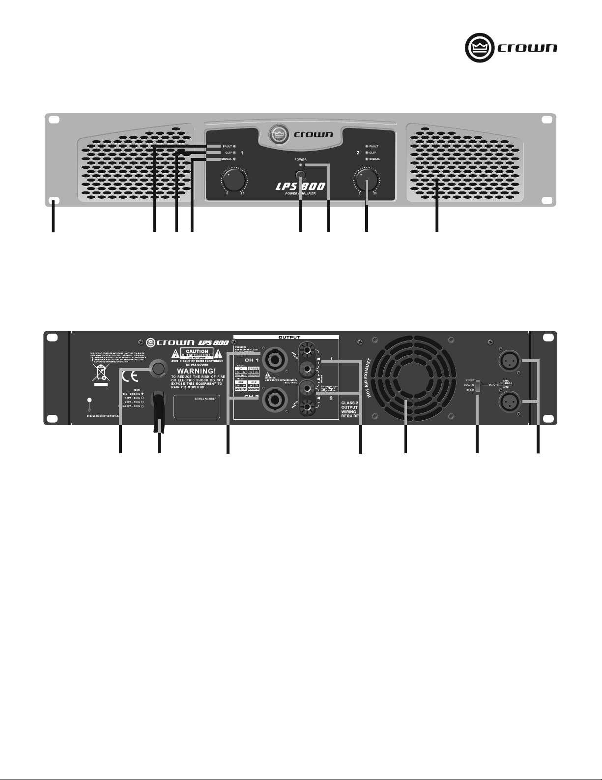
Front Panel
LPS Series Power Amplifiers
1
2
Figure 1. Front Panel Controls and Indicators
4
3
Back Panel
9
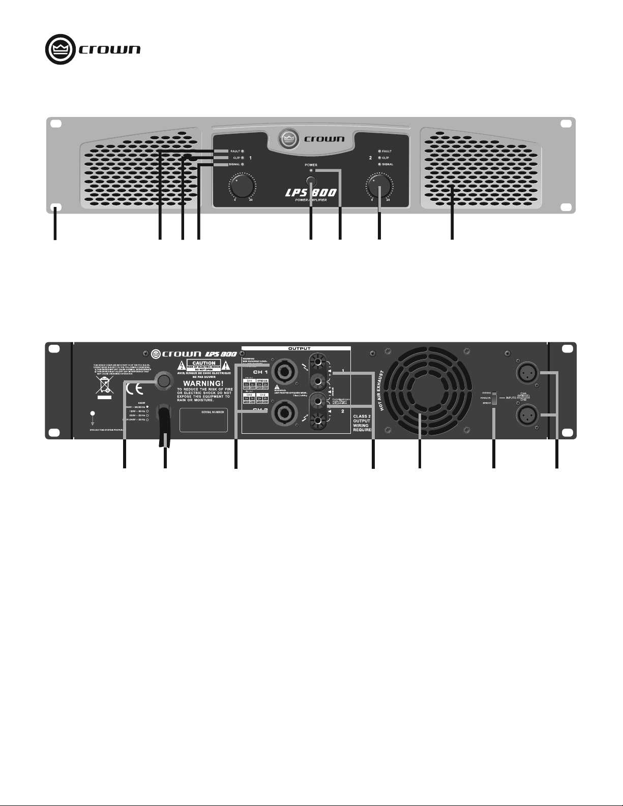
FRONT PANEL
1. Rack-mount hole (one of four)
2. Fault LED: Red LED, one per channel, indicates channel
shutdown.
3. Clip LED: Red LED, one per channel, flashes when signal is
audibly distorting.
4. Signal Presence LED: Green LED, one per channel,
flashes when input signal exceeds -40 dBu.
5. Power Switch: Push-on, push-off.
6. Power LED: Blue LED illuminates when amplifier is on.
7. Volume Control: Sets output level of each channel.
8. Grille: Allows flow-through ventilation from front to back.
10
11
Figure 2. Back Panel Controls and Connectors
5
6
BACK PANEL
9. Reset Button: Resets the circuit breaker.
10. Power Cable: Permanently attached cable connects to AC
11. Output Connectors: One Speakon
12. Output Connectors: One pair binding posts per channel
13. Grille: Allows flow-through ventilation from front to back.
14. Output Mode Switch: Stereo (dual), Parallel or Bridge.
15. Input Connectors: Balanced XLR, one per channel.
7
12
mains power.
loudspeakers.
connects to loudspeakers.
13
8
14 15
®
per channel connects to
page 4
Operation Manual
Page 5
LPS Series Power Amplifiers
Wiring
®
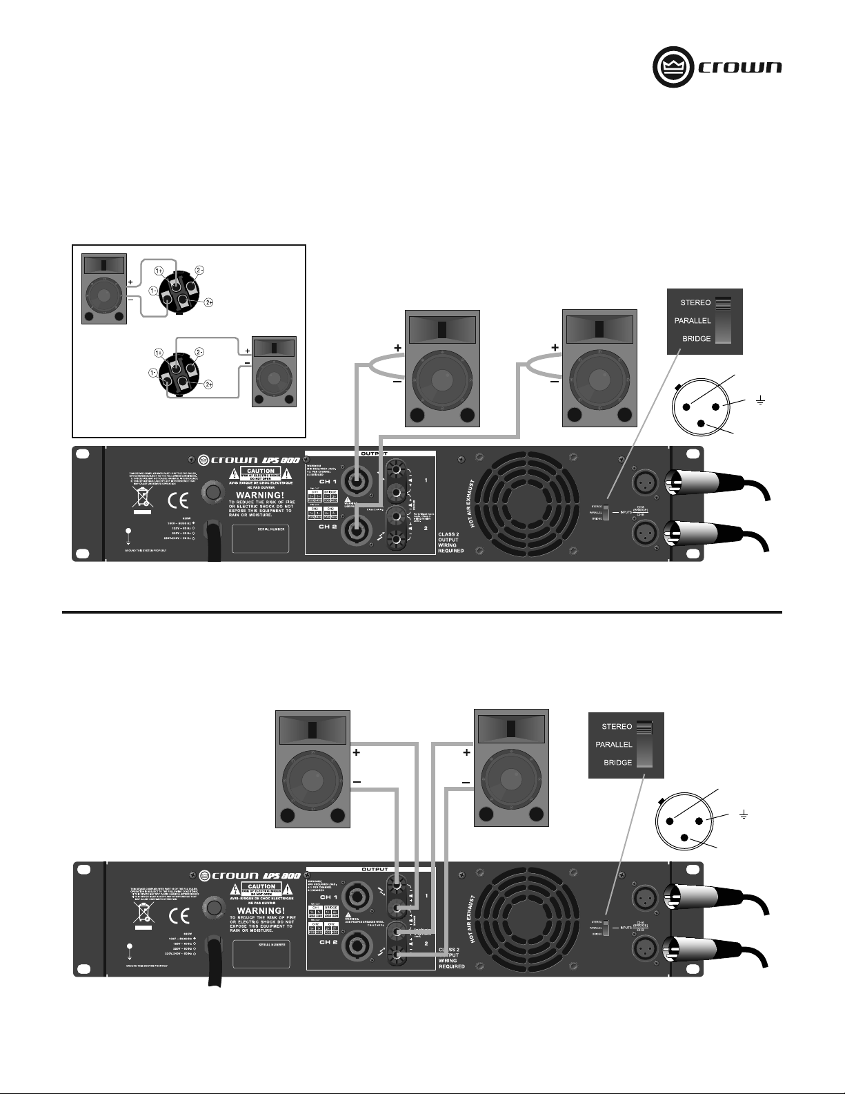
STEREO (DUAL) WIRING USING THE SPEAKON
1. See Figure 3. On the back panel, set the Output Mode Switch to STEREO.
2. Wire the speakers to the Speakon® connectors as shown.
CONNECTORS
®
Channel 2
Loudspeaker
Channel 1
Loudspeaker
Bottom
Speakon
(Channel 2)
Top Speakon
(Channel 1)
®
Figure 3. Stereo (Dual) Wiring With Speakon® Connectors
STEREO (DUAL) WIRING USING THE BINDING POST CONNECTORS
1. See Figure 4. On the back panel, set the Output Mode Switch to STEREO.
2. Wire the speakers to the binding post connectors as shown.
2 +
1
3
–
Input signals
Operation Manual
Figure 4. Stereo (Dual) Wiring With Binding Post Connectors
2 +
1
–
3
Input signals
page 5
Page 6
Wiring
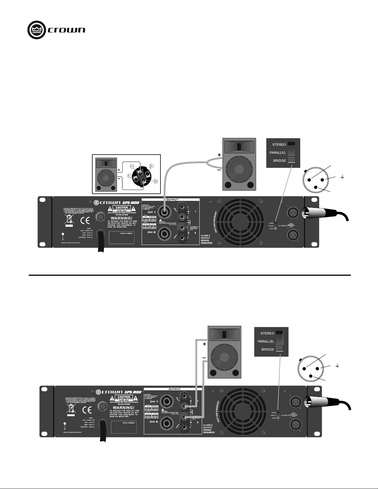
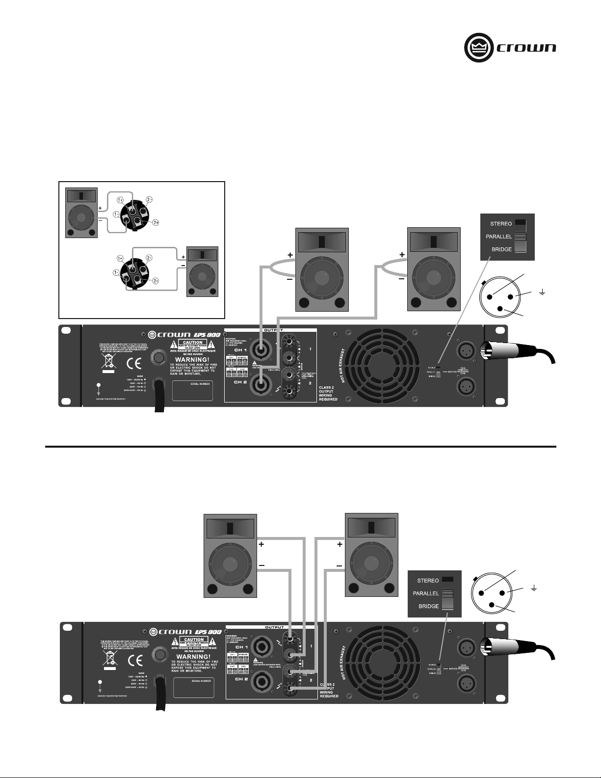
BRIDGE-MONO WIRING USING THE SPEAKON® CONNECTORS
Bridge-mono mode doubles the output power of the amplifier.
1. See Figure 5. On the back panel, set the Output Mode Switch to BRIDGE.
2. Wire the speaker to the Speakon
3. Only the Channel 1 Volume Control works in Bridge-mono mode.
®
connector as shown.
LPS Series Power Amplifiers
2 +
1
–
3
Figure 5. Bridge-Mono Wiring With Speakon
BRIDGE-MONO WIRING USING THE BINDING POST CONNECTORS
Bridge-mono mode doubles the output power of the amplifier.
1. See Figure 6. On the back panel, set the Output Mode Switch to BRIDGE.
2. Wire the speaker to the Binding Post connectors as shown.
3. Only the Channel 1 Volume Control works in Bridge-mono mode.
®
Connectors
Input signal
2 +
1
–
3
page 6
Input signal
Figure 6. Bridge-Mono Wiring With Binding Post Connectors
Operation Manual
Page 7
LPS Series Power Amplifiers
Wiring
®
PARALLEL WIRING USING THE SPEAKON
With this wiring, a signal sent to Channel 1 is paralleled to both channels so that it is reproduced by both speakers.
1. See Figure 7. On the back panel, set the Output Mode Switch to PARALLEL.
2. Wire the speakers to the Speakon® connectors as shown.
Top Speakon
(Channel 1)
Channel 1
Loudspeaker
CONNECTORS
Bottom
Speakon
(Channel 2)
Channel 2
Loudspeaker
Figure 7. Parallel Wiring With Speakon® Connectors
PARALLEL WIRING USING THE BINDING POST CONNECTORS
With this wiring, a signal sent to Channel 1 is paralleled to both channels so that it is reproduced by both speakers.
1. See Figure 8. On the back panel, set the Output Mode Switch to PARALLEL.
2. Wire the speakers to the binding post connectors as shown.
2 +
1
3
–
Input signal
Operation Manual
Figure 8. Parallel Wiring With Binding Post Connectors
2 +
1
–
3
Input signal
page 7
Page 8

Specifications
LPS Series Power Amplifiers
Guaranteed Minimum Power
1 kHz (EIA) with 0.5% THD
4 ohms stereo (per channel)
8 ohms stereo (per channel)
8 ohms bridge mono
LPS-800 LPS-1500 LPS-2500
300W
150W
600W
400W
250W
800W
Performance
Frequency Reponse (at 1 watt)
Total Harmonic Distortion (THD)
Intermodulation Distortion (IMD)
60 Hz and 7 kHz at 4:1, from full rated output to –30 dB
Slew Rate
Voltage Gain
Damping Factor (8 ohms), 10 Hz - 400 Hz
Signal-to-Noise Ratio (below rated power, 20 Hz to 20 kHz, A-weighted
Crosstalk (below rated power)
At 1 kHz
At 20 kHz
Input Sensitivity for full rated power at 4 ohms 1.25V rms
Input Impedance (nominal)
Balanced
Unbalanced
40 Hz - 20 kHz, +0/–3 dB
< 0.5%, 20 Hz - 20 kHz
< 0.3%
> 20V/μs > 23V/μs > 27V/μs
32 dB 32 dB 34 dB
> 300
> 100 dB
–76 dB
–58 dB
20 kilohms
10 kilohms
Connectors, Controls and Indicators
Input Connectors
Output Connectors (Speaker Connectors)
Front Panel Controls
Rear Panel Controls
Power Indicator
Signal Indicator
Clip (peak) Indicator
Fault Indicator
One balanced XLR for each channel
Speakon
Power on/off switch, one gain control per channel
Output mode switch: stereo (dual), parallel or bridge
One blue LED
One green LED per channel
One red LED per channel
Red LED, one per channel, indicates channel shutdown
®
and one pair binding post for each channel
Construction
Protection
Ventilation
Cooling
Dimensions (W x H x D)
Net Weight
Shipping Weight
Protection against short circuits, no-load, on/off muting, RF
interference. Stable into reactive or mismatched loads
Flow-through ventilation from front to back
Internal heat sinks with forced air. Fan cooled, speed regulated,
thermal protection
19" x 3.5" x 15.2" (482 mm x 89 mm x 386 mm)
20.9 lb (9.5 kg) 22.9 lb (10.4 kg) 29.8 lb (13.5 kg)
24.0 lb (10.9 kg) 26.0 lb (11.8 kg) 32.8 lb (14.9 kg)
725W
550W
1450W
page 8
Operation Manual
Page 9

LPS Series Power Amplifiers
Warranty
SUMMARY OF WARRANTY
Crown International, 1718 West Mishawaka Road, Elkhart, Indiana 46517-4095 U.S.A. warrants to you, the ORIGINAL PURCHASER and ANY SUBSEQUENT OWNER of each NEW Crown
product, for a period of one (1) year from the date of purchase by the original purchaser (the “warranty period”) that the new Crown product is free of defects in materials and workmanship.
We further warrant the new Crown product regardless of the reason for failure, except as excluded in this Warranty.
Warranty is only valid within the country in which the product was purchased.
ITEMS EXCLUDED FROM THIS CROWN WARRANTY
This Crown Warranty is in effect only for failure of a new Crown product which occurred within the Warranty Period. It does not cover any product which has been damaged because of any
intentional misuse, accident, negligence, or loss which is covered under any of your insurance contracts. This Crown Warranty also does not extend to the new Crown product if the serial
number has been defaced, altered, or removed.
WHAT THE WARRANTOR WILL DO
We will remedy any defect, regardless of the reason for failure (except as excluded), by repair, replacement, or refund. We may not elect refund unless you agree, or unless we are unable
to provide replacement, and repair is not practical or cannot be timely made. If a refund is elected, then you must make the defective or malfunctioning product available to us free and
clear of all liens or other encumbrances. The refund will be equal to the actual purchase price, not including interest, insurance, closing costs, and other finance charges less a reasonable
depreciation on the product from the date of original purchase. Warranty work can only be performed at our authorized service centers or at the factory. Warranty work for some products
can only be performed at our factory. We will remedy the defect and ship the product from the service center or our factory within a reasonable time after receipt of the defective product at
our authorized service center or our factory. All expenses in remedying the defect, including surface shipping costs in the United States, will be borne by us. (You must bear the expense
of shipping the product between any foreign country and the port of entry in the United States including the return shipment, and all taxes, duties, and other customs fees for such foreign
shipments.)
HOW TO OBTAIN WARRANTY SERVICE
You must notify us of your need for warranty service within the warranty period. All components must be shipped in a factory pack, which, if needed, may be obtained from us free of
charge. Corrective action will be taken within a reasonable time of the date of receipt of the defective product by us or our authorized service center. If the repairs made by us or our authorized service center are not satisfactory, notify us or our authorized service center immediately.
ONE YEAR LIMITED WARRANTY
DISCLAIMER OF CONSEQUENTIAL AND INCIDENTAL DAMAGES
YOU ARE NOT ENTITLED TO RECOVER FROM US ANY INCIDENTAL DAMAGES RESULTING FROM ANY DEFECT IN THE NEW CROWN PRODUCT. THIS INCLUDES ANY DAMAGE TO
ANOTHER PRODUCT OR PRODUCTS RESULTING FROM SUCH A DEFECT. SOME STATES DO NOT ALLOW THE EXCLUSION OR LIMITATIONS OF INCIDENTAL OR CONSEQUENTIAL
DAMAGES, SO THE ABOVE LIMITATION OR EXCLUSION MAY NOT APPLY TO YOU.
WARRANTY ALTERATIONS
No person has the authority to enlarge, amend, or modify this Crown Warranty. This Crown Warranty is not extended by the length of time which you are deprived of the use of the new
Crown product. Repairs and replacement parts provided under the terms of this Crown Warranty shall carry only the unexpired portion of this Crown Warranty.
DESIGN CHANGES
We reserve the right to change the design of any product from time to time without notice and with no obligation to make corresponding changes in products previously manufactured.
LEGAL REMEDIES OF PURCHASER
THIS CROWN WARRANTY GIVES YOU SPECIFIC LEGAL RIGHTS, YOU MAY ALSO HAVE OTHER RIGHTS WHICH VARY FROM STATE TO STATE. No action to enforce this Crown Warranty
shall be commenced after expiration of the warranty period.
THIS STATEMENT OF WARRANTY SUPERSEDES ANY OTHERS CONTAINED IN THIS MANUAL FOR CROWN PRODUCTS. 09/07
Operation Manual
page 9
Page 10
Manuel d'utilisation
LPS-800
LPS-1500 LPS-2500
Versions dans d'autres langues: Pour obtenir des informations concernant l'utilisation de ce produit dans d'autres langues, veuillez
contacter votre distributeur Crown local. Si vous avez besoin d'aide pour localiser votre distributeur local, veuillez contacter Crown au
574-294-8000.
Ce manuel n'inclut pas tous les détails de conception, production ou variations de l'équipement. Il ne couvre également pas toutes les
situations possibles pouvant survenir au cours de l'installation, de l'exploitation ou de l'entretien.
Les informations figurant dans ce manuel sont considérées comme exactes à la date de publication. Toutefois, des mises à jour de ces
informations sont peut-être survenues. Pour obtenir la dernière version de ce manuel, visitez le site web de Crown www.crownaudio.com
Avis concernant les marques déposées: Crown and Crown Audio sont des marques déposées de Crown International. Les autres
marques de commerce appartiennent à leurs propriétaires respectifs.
©2008 by Crown Audio®, Inc., 1718 W. Mishawaka Rd., Elkhart, Indiana 46517-9439 U.S.A. Téléphone :574-294-8000
140481-4
5/09
Page 11

LPS Series Power Amplifiers
Crown International, Inc.
Publiée par : Crown International, Inc.
1718 W. Mishawaka Road
Elkhart, Indiana 46517
U.S.A.
Nom et adresse du
représentant européen :
David Budge
10 Harvest Close
Yateley GU46 6YS
Royaume-Uni
Type d'équipement : Amplificateurs de puissance audio du commerce
Nom de la famille de produits : LPS
Noms des modèles : LPS-800, LPS-1500, LPS-2500
Normes EMC :
EN 55103-1:1997 Compatibilité électromagnétique- Norme de famille de produits pour les appareils Audio, Vidéo, Audio-Visuels et Divertissement Appareil de contrôle de l'éclairage à usage
professionnel, Partie 1: Emissions
EN 55103-1:1997 Emissions de champ magnétique-Annexe A @ 10 cm et 20 cm
EN 61000-3-2:2001 Limites des émissions du courant harmonique (courant d'entrée de l'équipement inférieur ou égal à 16 A par phase)
EN 61000-3-3:2002 Limites des fluctuations de tension et flicker dans les systèmes d'alimentation basse tension Courant nominal inférieur ou égal à 16A
EN 55022:2003 Limites et méthodes de mesure des caractériques de perturbation radioélectrique d'ITE : Rayonnement, Limites Classe B; Conduit, Classe A
EN 55103-2:1997 Compatibilité électromagnétique- Norme de famille de produits pour les appareils Audio, Vidéo, Audio-Visuels et Divertissement Appareil de contrôle de l'éclairage à usage
professionnel, Partie 2 : Immunité
EN 61000-4-2:2001 Immunité de décharge électrostatique (Environnement E2-Critère B, 4k V Contact, Evacuation d'air 8k V)
EN 61000-4-3:2001 Rayonnement, Fréquence radio, Immunité électromagnétique (Environnement E2, critère A)
EN 61000-4-4:2001 Transitoire électrique rapide/Immunité aux explosions (Critère B)
EN 61000-4-5:2001 Immunité surtension (Critère B)
EN 61000-4-6:2003 Immunité aux perturbations conduites induites par champs radioélectriques (Critère A)
EN 61000-4-11:2001 Baisses de tension, Interruptions courtes et Variation de tension
Norme de sécurité :
IEC 60065: 2001 7e Ed. Exigences de sécurité - Audio, Vidéo et appareils électroniques similaires
Je certifie que le produit identifié ci-dessus est conforme aux exigences de la Directive du conseil de l'EMC 89/336/CEE telle que modifiée par 92/31/CEE, et à la Directive basse tension
73/23/EES telle que modifiée par 93/68/CEE.
DECLARATION DE CONFORMITE
QUESTIONS DE CONFORMITE UNIQUEMENT :
Sue Whitfield
574-294-8289
swhitfield@crownintl.com
Signé par
_____________________
Andrew Stump
Titre : Vice président senior de la Fabrication
En raison des harmoniques du courant, nous vous recommandons de contacter votre fournisseur d'électricité avant tout raccordement.
En raison des harmoniques du courant, nous vous recommandons de contacter votre compagnie d’électricité avant connexion.
Operation Manual
Date de publication : 1er juillet 2008
page 11
Page 12
Instructions importantes relatives à la sécurité
1. Veuillez lire ces instructions.
2. Veuillez conserver ces instructions.
3. Respectez tous les avertissements.
4. Suivez toutes les instructions.
5. Ne pas utiliser cet appareil à proximité de l'eau.
6. Nettoyer exclusivement au moyen d'un linge sec.
7. Ne pas bloquer des ouvertures de ventilation. Installer conformément
aux instructions du fabricant.
8. Ne pas installer à proximité de sources de chaleur telles que
des radiateurs, registres de chaleur ou autre appareil (dont des
amplificateurs) qui produisent de la chaleur.
9. Ne pas contrevenir à la sécurité de la fiche polarisée ou de type terre.
Une fiche polarisée est munie de deux lames dont l'une est plus large
que l'autre. Une fiche polarisée est munie de deux lames et d'une
broche de raccordement à la terre. La lame large ou la troisième
broche est installée pour optimiser votre sécurité. Si la fiche fournie ne
correspond pas à votre prise, consultez un électricien en vue de faire
remplacer la prise obsolète.
10. Assurez-vous que personne ne marche sur le cordon d'alimentation
ou qu'il est pas pincé, en particulier sur les prises, prises de courant
et à l'endroit où il sort de l'appareil.
11. Utiliser exclusivement les accessoires spécifiés par le fabricant.
12. Utiliser uniquement avec un chariot, tripode, console ou table
spécifiés par le fabricant ou vendus avec l'appareil. En cas d'utilisation
d'un chariot, prendre des précautions lorsque vous déplacez le chariot
/appareil pour éviter toute blessure due à une chute.
13. Débranchez cet appareil au cours des orages ou si vous ne l'utilisez
pas pendant une durée prolongée.
14. Confiez tout l'entretien à un personnel d'entretien qualifié. Un entretien
est nécessaire lorsque l'appareil a été endommagé, par exemple, si le
cordon d'alimentation ou la fiche sont endommagés, si du liquide a
été projeté sur l'appareil ou si des objets sont tombés dans l'appareil,
si l'appareil a été exposé à la pluie ou à l'humidité, ne fonctionne pas
correctement ou est tombé.
15. Utilisez la fiche principale pour débrancher l'appareil du secteur.
16. AVERTISSEMENT : POUR REDUIRE LE RISQUE D'INCENDIE OU
DE DECHARGE ELECTRIQUE, NE PAS EXPOSER L'APPAREIL A LA
PLUIE OU A L'HUMIDITE.
17. NE PAS EXPOSER CET EQUIPEMENT A DES GOUTTES OU A DES
PROJECTIONS D'EAU ET S'ASSURER QU'AUCUN OBJET REMPLI DE
LIQUIDE, TEL QU'UN VASE, N'EST PLACE SUR L'EQUIPEMENT.
18. LA FICHE PRINCIPALE DU CORDON D'ALIMENTATION DOIT RESTER
EXPLOITABLE A TOUT MOMENT.
POUR PRÉVENIR LES DÉCHARGES ÉLECTRIQUES, NE PAS RETIRER LES
CAPOTS INFÉRIEURS OU SUPÉRIEURS. AUCUNE PIÈCE SUSCEPTIBLE D'ÊTRE
ENTRETENUE PAR L'UTILISATEUR NE SE TROUVE À L'INTÉRIEUR. CONFIEZ TOUT
L'ENTRETIEN À UN PERSONNEL D'ENTRETIEN QUALIFIÉ.
POUR DEBRANCHER INTEGRALEMENT CET EQUIPEMENT DU COURANT CA,
DEBRANCHEZ LE CORDON D'ALIMENTATION DE LA PRISE CA. LA FICHE
PRINCIPALE DU CORDON D'ALIMENTATION DOIT RESTER EXPLOITABLE A TOUT
MOMENT.
LPS Series Power Amplifiers
FAITES ATTENTION A CES SYMBOLES : Le triangle contenant un éclair
permet d'alerter l'utilisateur du risque de décharge électrique.
Le triangle contenant un point d'exclamation sert à alerter l'utilisateur
d'instructions d'exploitation ou de maintenance importantes.
IMPORTANT
Les amplificateurs de la Série LPS nécessitent un câblage de sortie de Classe 2..
CHAMPS MAGNÉTIQUES
ATTENTION ! Ne pas installer des équipements sensibles à gain élevé tels
que des préamplificateurs ou des platines de magnétophone au-dessus ou
en dessous de l'unité. Cet amplificateur étant doté d'une densité électrique
élevée, son champ magnétique élevé peut générer des bourdonnements sur
les dispositifs non blindés situés à proximité. Le champ est plus important
juste au-dessus et en dessous de l'unité.
Si un rack d'équipements est utilisé, nous recommandons d'installer le ou
les amplificateurs en bas du rack et le préamplificateur ou autre équipement sensible en haut du rack.
Prévoir un espace standart de montage de rack de deux pouces sur
chaque côté et de 5cm à l'arrière.
AVIS DE CONFORMITE FCC
Ce dispositif est conforme à la partie 15 des Réglementations FCC. L'exploitation
est soumise aux deux conditions suivantes : (1) Ce dispositif ne doit pas provoquer
d'interférences dangereuses et (2) ce dispositif doit accepter toute interférence
reçue, dont les interférences pouvant générer un fonctionnement non souhaité.
ATTENTION : Les modifications non expressément approuvées par la partie
responsable de la conformité peuvent annuler le permis d'exploitation de
l'équipement de l'utilisateur.
REMARQUE : Cet équipement a été testé et est conforme aux limites d'un dispositif
numérique de Classe B, conformément à la partie 15 des Réglementations FCC. Ces
limites sont conçues pour fournir une protection raisonnable contre les interférences
dangereuses dans une installation résidentielle. Cet équipement génère, utilise et
peut irradier de l'énergie de fréquence radio et, s'il n'est pas installé conformément
au manuel d'instructions, peut provoquer des interférences dangereuses sur les
communications radio. Toutefois, il n'est pas garanti qu'aucune interférence ne va
survenir dans une installation particulière. Si cet équipement provoque des interférences dangereuses sur la réception de la radio ou de la télévision, ce qui peut
être déterminé en éteignant et en allumant l'équipement, l'utilisateur est encouragé
à tenter de corriger l'interférence au moyen de l'une ou de plusieurs des mesures
suivantes :
s2£ORIENTEZOUD£PLACEZLgANTENNEDER£CEPTION
s!UGMENTEZLADISTANCEENTRELg£QUIPEMENTETLER£CEPTEUR
s2ACCORDEZLg£QUIPEMENTÜUNESORTIESURUNCIRCUITDIFF£RENTDECELUIAUQUELLE
récepteur est raccordé.
s$EMANDEZÜVOTREFOURNISSEURLESCOORDONN£ESDgUNTECHNICIEN462ADIOEXP£RI
menté pour obtenir de l'aide.
Introduction
élicitations pour votre achat d'un amplificateur de puissance Crown®
F
LPS. Les trois modèles de la série sont puissants, solides et fiables. Ils
sont conçus pour les applications telles que les églises, tournées de concert,
scènes, boîtes de nuit, bars ou tout endroit nécessitant l'installation d'un
amplificateur.
Les caractéristiques comprennent des entrées XLR, sorties Speakon
bornes, mode stéréo/parallèle/bridge-mono, voyant de fonctionnement/
défaut/signal/clip, ventilation à air forcé, protection contre les courtscircuits, circuit ouvert, silencieux on/off et interférence des ondes radio.
page 12
®
et à
Installation
Conçue pour être installée dans un rack d'équipements standard 19 pouces,
l'unité n'occupe que deux espaces de rack. Fixez l'unité avec les quatres vis
de montage en rack et les rondelles à collerette. Pour un refroidissement
optimal, installez les amplificateurs sans espace prévu entre les éléments. Si
les amplificateurs sont installés en rack avec des espaces, des panneaux de
rack solides non ventilés sont recommandés entre les amplificateurs. Prévoir
un espace standart de montage de rack de deux pouces sur chaque côté et de
5cm à l'arrière.
Cette unité est fournie avec un ventilateur à vitesse variable qui règle
automatiquement la vitesse du ventilateur en fonction de la température de
l'unité pendant le fonctionnement. Le débit de l'air va de l'avant vers l'arrière,
ne pas placer d'objet susceptibles d'empêcher l'air de sortir de l'unité depuis
sa ventilation arrière..
Operation Manual
Page 13
LPS Series Power Amplifiers
Panneau avant
1
2
Figure 1. Commandes et connecteurs du panneau avant
4
3
Panneau arrière
9
PANNEAU AVANT
1. Orifice de montage en rack (un sur quatre)
2. DEL défaut : DEL rouge, un par canal, indique l'interruption du canal.
3. DEL clip : DEL rouge, un par canal, clignote lorsque le signal est
déformé de manière audible.
4. DEL Signal de présence : DEL vert, un par canal, clignote lorsque
le signal d'entrée dépasse -40 dBu.
5. Commutateur mise en service : Appuyer pour allumer, appuyer
pour éteindre.
6. DEL de mise en service : Le DEL bleu s'allume lorsque
l'amplificateur est activé.
7. Contrôle du volume : Règle le niveau de sortie de chaque canal.
8. Grille: Permet une ventilation intégrale de l'avant vers l'arrière.
10
Figure 2. Commandes et connecteurs du panneau arrière
11
5
6
PANNEAU ARRIERE
9. Bouton de réinitialisation : Réinitialise le coupe circuit.
10. Câble d'alimentation : Le câble raccordé de façon perman-
11. Connecteurs de sortie : Un Speakon
12. Conecteurs de sortie ! Une paire de bornes par canal se
13. Grille: Permet une ventilation intégrale de l'avant vers l'arrière.
14. Commutateur Mode sortie : Stéréo (dual), Parallèle ou Bridge.
15. Connecteurs d'entrée : XLR équilibré, un par canal.
7
12
ente se connecte à l'alimentation électrique CA.
aux enceintes.
raccord aux enceintes.
13
8
14 15
®
par canal se raccorde
Operation Manual
page 13
Page 14

Câblage
LPS Series Power Amplifiers
CABLAGE STEREO (DUAL) UTILISANT LES CONNECTEURS SPEAKON
®
1. Se reporter à la Figure 3. Sur le panneau arrière, régler le Commutateur de mode sortie sur STEREO.
2. Raccorder les enceintes aux connecteurs Speakon® tel que représenté.
®
Speakon
supérieur
(Canal 1)
Canal 1
Enceinte
®
Speakon
inférieur
(Canal 2)
Canal 2
Enceinte
Figure 3. Câblage Stéréo (Dual) avec connecteurs Speakon
2 +
1
3
–
Signaux d'entrée
®
CABLAGE STEREO (DUAL) UTILISANT LES CONNECTEURS A BORNES
1. Se reporter à la Figure 4. Sur le panneau arrière, régler le Commutateur de mode sortie sur STEREO.
2. Raccorder les enceintes aux connecteurs à bornes tel que représenté.
Figure 4. Câblage Stéréo (Dual) avec connecteurs à bornes
page 14
2 +
1
–
3
Signaux d'entrée
Operation Manual
Page 15

LPS Series Power Amplifiers
Câblage
CABLAGE BRDIGE MONO UTILISATION LES CONNECTEURS SPEAKON
®
Le mode Bridge-mono double la puissance de sortie de l'amplificateur.
1. Se reporter à la Figure 5. Sur le panneau arrière, régler le Commutateur de mode sortie sur BRIDGE.
2. Raccorder l'enceinte au connecteur Speakon® tel que représenté.
3. Seul le contrôle du volume du Canal 1 fonctionne en mode Bridge-mono.
Figure 5. Câblage Bridge-Mono avec connecteurs Speakon
2 +
1
–
3
Signaux
d'entrée
®
CABLAGE BRIDGE MONO UTILISANT LES CONNECTEURS A BORNES
Le mode Bridge-mono double la puissance de sortie de l'amplificateur.
1. Se reporter à la Figure 6. Sur le panneau arrière, régler le Commutateur de mode sortie sur BRIDGE.
2. Raccorder l'enceinte aux connecteurs à bornes tel que représenté.
3. Seul le contrôle du volume du Canal 1 fonctionne en mode Bridge-Mono.
Figure 6. Câblage Bridge-Mono avec connecteurs à bornes
Operation Manual
2 +
1
–
3
Signaux
d'entrée
page 15
Page 16

LPS Series Power Amplifiers
Câblage
CABLAGE PARALLELE UTILISANT LES CONNECTEURS SPEAKON
Avec ce câblage, un signal envoyé au Canal 1 est mis en parallèle sur les deux canaux, il est ainsi reproduit par les deux enceintes..
1. Se reporter à la Figure 7. Sur le panneau arrière, régler le Commutateur de mode sortie sur PARALLELE.
2. Raccorder les enceintes aux connecteurs Speakon® tel que représenté.
Speakon
supérieur
(Canal 1)
Canal 1
Enceinte
®
Speakon
inférieur
(Canal 2)
Canal 2
Enceinte
Figure 7. Câblage Parallèle avec connecteurs Speakon
®
CABLAGE PARALLELE UTILISANT LES CONNECTEURS A BORNES
Avec ce câblage, un signal envoyé au Canal 1 est mis en parallèle sur les deux canaux, il est ainsi reproduit par les deux enceintes.
1. Se reporter à la figure 8. Sur le panneau arrière, régler le commutateur Mode de sortie sur PARALLELE.
2. Raccorder les enceintes aux connecteurs à bornes tel que représenté.
2 +
3
Signal
d'entrée
1
–
page 16
Figure 8. Câblage parallèle avec connecteurs à bornes
2 +
1
–
3
Signaux
d'entrée
Operation Manual
Page 17

LPS Series Power Amplifiers
Spécifications
Puissance Minimum Guarantie
1 kHz (EIA) avec 0,5% THD
4 ohms stéréo (par canal)
8 ohms stéréo (par canal)
8 ohms bridge mono
LPS-800 LPS-1500 LPS-2500
300W
150W
600W
400W
250W
800W
Performances
Réponse de fréquence (à 1 watt)
Distortion harmonique totale (THD)
Distortion d'intermodulation (IMD)60 Hz et 7 kHz at 4:1, de la sortie à
plein régime à –30 dB
Vitesse de balayage
Gain de tension
Facteur d'amortissement (8 ohms), 10 Hz - 400 Hz
Ratio Signal-Bruit (sous la puissance nominale, 20 Hz à 20 kHz, pondéré A
Diaphonie (sous la puissance nominale)
A 1 kHz
A 20 kHz
Sensibilité d'entrée pour puissance à plein régime à 4 ohms 1,25V rms
Impédance d'entrée (nominale)
Equilibrée
Non équilibrée
40 Hz - 20 kHz, +0/–3 dB
< 0,5%, 20 Hz - 20 kHz
< 0,3%
> 20V/μs > 23V/μs > 27V/μs
32 dB 32 dB 34 dB
> 300
> 100 dB
–76 dB
–58 dB
20 kilohms
10 kilohms
Connecteurs, Commandes et Voyants
Connecteurs d'entrée
Connecteurs de sortie (Connecteurs enceinte)
Commandes du panneau avant
Commandes du panneau arrière
Voyant de fonctionnement
Voyant de signal
Voyant clip (pic)
Voyant de défaut
Un XLR équilibré pour chaque canal
Speakon
Commutateur on/off, une commande de gain par canal
Commutateur mode sortie : stéréo (dual), Parallèle ou Bridge.
Un DEL bleu
Un DEL Vert par canal
Un DEL rouge par canal
DEL rouge, un par canal, indique l'interruption du canal.
®
et une paire de bornes pour chaque canal
Construction
Protection
Ventilation
Refroidissement
Dimensions (L x H x P)
Poids net
Poids d'expédition
Protection contre les courts circuits, circuit ouvert, silencieux
on/off, Interférences RF. Stable dans des charges réactives ou
mal accordées.
Ventilation intégrale de l'avant vers l'arrière.
Dissipateurs thermiques internes à air forcé. Refroidi par
ventilateur à vitesse régulée, protection thermique
19" x 3.5" x 15.2" (482 mm x 89 mm x 386 mm)
20.9 lb (9,5 kg) 22.9 lb (10,4 kg) 29.8 lb (13,5 kg)
24.0 lb (10,9 kg) 26.0 lb (11,8 kg) 32.8 lb (14,9 kg)
725W
550W
1450W
Operation Manual
page 17
Page 18

GARANTIE
LPS Series Power Amplifiers
RESUME DE LA GARANTIE
Crown International, 1718 West Mishawaka Road, Elkhart, Indiana 46517-4095 U.S.A. vous garantit, en qualité d'ACHETEUR D'ORIGINE et de TOUT PROPRIETAIRE ULTERIEUR de chaque
produit Crown NEUF, pendant une durée d'un (1) an à compter de la date d'achat par l'acheteur d'origine (la "durée de garantie") que le produit Crown neuf est exempt de défauts matériels
et de main d'oeuvre. Nous garantissons également le produit Crown neuf, quel que soit le motif de son dysfonctionnement, sauf s'agissant des exclusions figurant dans cette Garantie.
La garantie n'est valable que dans le pays dans lequel le produit a été acheté.
ELEMENTS EXCLUS DE CETTE GARANTIE DE CROWN
Cette Garantie de Crown ne concerne que le dysfonctionnement d'un produit de Crown neuf et survenu pendant la Durée de la garantie. Elle ne couvre pas tout produit endommagé suite à
une mauvaise utilisation non intentionnelle, un accident, une négligence ou une perte couverts par vos contrats d'assurance. Cette Garantie de Crown ne s'étend pas au produit Crown neuf
si le numéro de série a été effacé, modifié ou enlevé.
LE GARANT S'ENGAGE AUX ELEMENTS SUIVANTS
Nous réparons tous défauts, quel que soit le motif du dysfonctionnement (hormis les exclusions) par une réparation, un remplacement ou un remboursement. Nous pouvons ne pas opter
pour le remboursement sauf si vous l'acceptez, ou si nous ne pouvons fournir un remplacement, et si la réparation n'est pas possible ou réalisable dans des délais acceptables. En cas de
remboursement, vous devez nous fournir le produit défecteux ou ne fonctionnant pas correctement libre de servitude ou autre nantissement. Le montant du remboursement sera égal au
prix d'achat réel, sans intérêt, assurance, frais d'emballage et autres frais moins un amortissement raisonnable sur le produit à compter de la date d'achat. Les travaux sous garantie ne peuvent être effectués que dans nos centres de réparation agréés ou en usine. Les travaux sous garantie de certains produits ne peuvent être effectués que dans notre usine. Nous réparons le
défaut et expédions le produit depuis le centre de réparation ou notre usine dans un délai raisonnable après réception du produit défectueux dans notre centre de réparation agréé ou notre
usine. Tous les frais de réparation du défaut, dont les frais d'expédition aux Etats-Unis, sont à notre charge. (Vous devez prendre en charge les frais d'expédition entre tout pays étranger le
port d'entrée aux Etats-Unis et l'expédition de retour, ainsi que toutes taxes et autres taxes douanières concernant de telles expéditions étrangères)
COMMENT OBTENIR UNE REPARATION SOUS GARANTIE
Vous devez nous indiquer que vous avez besoin d'une réparation sous garantie au cours de la durée de la garantie. Tous les composants doivent être expédiés dans un carton d'usine
qui, si nécessaire, peut être obtenu sans frais sur demande auprès de nos services. Les actions correctrices sont entreprises dans un délai raisonnable à compter de la date de réception
du produit défectueux par nos soins ou notre centre de réparation agréé. Si les réparations effectuées par nous-même ou le centre de réparation agréé ne sont pas satisfaisantes, veuillez
immédiatement nous le signaler ou le signaler au centre de réparation agréé.
GARANTIE LIMITEE A UN AN
AVIS DE NON RESPONSABILITE CONCERNANT LES DOMMAGES IMMATERIELS ET ACCESSOIRES
VOUS NE POUVEZ NOUS RECLAMER TOUT DOMMAGE IMMATERIEL EMANANT DE TOUT DEFAUT DANS LE PRODUIT CROWN NEUF. CECI COMPREND LES DOMMAGES SUBIS PAR
UN OU PLUSIEURS AUTRES PRODUITS ET EMANANT D'UN TEL DEFAUT. CERTAINS ETATS INTERDISENT L'EXCLUSION OU LES LIMITATIONS DES DOMMAGES IMMATERIELS OU
ACCESSOIRES, LA LIMITATION OU L'EXCLUSION PEUT PAR CONSEQUENT NE PAS VOUS CONCERNER.
MODIFICATIONS DE GARANTIE
Personne n'est en droit d'étendre, de modifier ou d'altérer cette Garantie de Crown. Cette garantie de Crown n'est pas prolongée au cours de la durée pendant laquelle vous ne pouvez pas
utiliser le produit de Crown. Les réparations et pièces de rechange fournies en vertu de cette Garantie de Crown sont soumises à la partie non expirée de cette Garantie de Crown.
MODIFICATIONS DE LA CONCEPTION
Nous nous réservons le droit de modifier la conception de tout produit de temps à autres sans préavis et sans obligation de procéder aux modifications correspondantes sur les produits
fabriqués auparavant.
RECOURS JURIDIQUES DE L'ACHETEUR
CETTE GARANTIE DE CROWN VOUS CONFERE DES DROITS LEGAUX SPECIFIQUES, VOUS POUVEZ EGALEMENT BENEFICIER D'AUTRES DROITS VARIABLES EN FONCTION DES
ETATS. Aucune action visant à exécuter cette Garantie de Crown ne pourra être entamée après l'expiration de la durée de la garantie.
CETTE DECLARATION ANNULE ET REMPLACE TOUTES AUTRES DECLARATIONS CONTENUES DANS CE MANUEL ET CONCERNANT LES PRODUITS DE CROWN. 09/07
page 18
Operation Manual
Page 19

Bedienungsanleitung
LPS-800
LPS-1500 LPS-2500
Weitere Sprachversionen: Um Informationen über die Nutzung dieses Produktes in anderen Sprachen zu erhalten, wenden Sie sich bitte
an Ihren örtlichen Crown-Händler. Wenn Sie Hilfe dabei benötigen, Ihren örtlichen Händler ausfindig zu machen, kontaktieren Sie Crown bitte
unter 574-294-8000.
Dieses Handbuch enthält nicht alle Einzelheiten zu Design, Herstellung oder Varianten des Gerätes. Es deckt auch nicht jeden möglichen Fall
ab, der während Installation, Betrieb oder Wartung auftreten kann.
Die in diesem Handbuch enthaltenen Informationen waren bei Erscheinungsdatum zutreffend. Es können jedoch Aktualisierungen zu diesen
Informationen vorliegen. Um die neueste Version dieses Handbuchs zu erhalten, besuchen Sie bitte die Crown-Webseite auf www.crownaudio.com.
Rechtlicher Hinweis: Crown und Crown Audio sind eingetragene Handelsmarken von Crown International. Sonstige Handelsmarken sind
das Eigentum ihrer jeweiligen Eigentümer.
©2008 by Crown Audio®, Inc., 1718 W. Mishawaka Rd., Elkhart, Indiana 46517-9439 U.S.A. Telefon: 574-294-8000
140481-4
5/09
Page 20

LPS Series Power Amplifiers
Crown International, Inc.
Ausgestellt von: Crown International, Inc.
1718 W. Mishawaka Road
Elkhart, Indiana 46517 U.S.A.
Name und Adressen des
europäischen Vertreters:
David Budge
10 Harvest Close
Yateley GU46 6YS
Vereinigtes Königreich
Gerätetyp: Kommerzielle Audio-Endstufe
Bezeichnung der Produktfamilie: LPS
Bezeichnung des Models: LPS-800, LPS-1500, LPS-2500
EMV-Normen:
EN 55103-1:1997 Elektromagnetische Verträglichkeit - Produktfamiliennorm für Audio-, Video- und audiovisuelle Einrichtungen sowie für Studio-Lichtsteuereinrichtungen für
professionellen Einsatz - Teil 1: Störaussendungen
EN 55103-1:1997 Magnetfeld-Emission Anhang A @ 10 cm und 20 cm
EN 61000-3-2:2001 Grenzwerte für Oberschwingungsströme (Geräte-Eingangsstrom bis einschließlich 16 A je Leiter)
EN 61000-3-3:2002 Grenzwerte für Spannungsschwankungen und Flicker in Niederspannungsnetzen für Geräte mit einem Eingangsstrom bis zu 16 A
EN 55022:2003 Grenzwerte und Messverfahren für Funkstörungen von Einrichtungen der Informationstechnik: Eingestrahlt, Grenzwerte Klasse B; leitungsgeführt, Klasse A
EN 55103-2:1997 Elektromagnetische Verträglichkeit - Produktfamiliennorm für Audio-, Video- und audiovisuelle Einrichtungen sowie für Studio-Lichtsteuereinrichtungen für
professionellen Einsatz, Teil 2: Störfestigkeit
EN 61000-4-2:2001 Störfestigkeit gegen Entladung statischer Elektrizität (Umgebung E2-Kriterium B, 4k V Kontakt, 8k V Luftentladung)
EN 61000-4-3:2001 Störfestigkeit gegen hochfrequente elektromagnetische Felder (Umgebung E2, Kriterium A)
EN 61000-4-4:2001 Störfestigkeit gegen schnelle transiente elektrische Störgrößen/Burst (Kriterium B)
EN 61000-4-5:2001 Störfestigkeit gegen Stoßspannungen/Surge (Kriterium B)
EN 61000-4-6:2003 Störfestigkeit gegen leitungsgeführte Störgrößen, induziert durch hochfrequente Felder (Kriterium A)
EN 61000-4-11:2001 Störfestigkeit gegen Spannungseinbrüche, Kurzzeitunterbrechungen und Spannungsschwankungen
Sicherheitsstandard:
IEC 60065: 2001 7. Ausg. Audio-, Video- und ähnliche elektronische Geräte – Sicherheitsanforderungen
Ich bestätige, dass das oben beschriebene Produkt mit den Anforderungen der EMV-Richtlinie 89/336/EEC, geändert durch 92/31/EEC, und der Richtlinie 73/23/EES über niedere
Spannungen, geändert durch 93/68/EEC, übereinstimmt.
KONFORMITÄTSERKLÄRUNG
FRAGEN BEZÜGLICH KONFORMITÄT
BITTE AUSSCHLIESSLICH AN:
Sue Whitfield
574-294-8289
swhitfield@crownintl.com
Unterschrift
page 20
_____________________
Andrew Stump
Titel: Senior Vice President der Herstellungg
Aufgrund der Oberschwingungen im Netzstrom empfehlen wir, vor der Verkabelung Ihren Lieferanten zu kontaktieren.
En raison des harmoniques du courant, nous vous recommandons de contacter votre compagnie d’électricité avant connexion.
Ausstellungsdatum: 1. Juli 2008
Operation Manual
Page 21

LPS Series Power Amplifiers
Wichtige Sicherheitshinweise
1. Lesen Sie diese Hinweise.
2. Bewahren Sie diese Hinweise auf.
3. Beachten Sie alle Warnhinweise.
4. Befolgen Sie alle Anweisungen.
5. Verwenden Sie dieses Gerät nicht in der Nähe von Wasser.
6. Reinigen Sie es ausschließlich mit einem trockenen Tuch
7. Blockieren Sie keine Lüftungsöffnungen. Stellen Sie es gemäß den
Herstelleranweisungen auf.
8. Stellen Sie es nicht in der Nähe von Wärmequellen wie beispielsweise
Heizkörpern, Raumheizungen, Öfen oder sonstigen Geräten (einschließlich
Verstärkern), die Wärme erzeugen, auf.
9. Versuchen Sie niemals, die polarisierte Leitung bzw. Erde hochzulegen
oder zu umgehen. Ein polarisierter Stecker ist mit zwei flachen Stiften
unterschiedlicher Breite versehen. Ein Stecker mit Erdung weist zwei Stifte
und eine Erdungsbuchse auf. Der breitere Stift oder die Buchse dienen Ihrer
Sicherheit. Wenn der beiliegende Stecker nicht in Ihre Steckdose passt,
sollten Sie einen Elektriker bitten, die Steckdose zu erneuern.
10. Verhindern Sie, dass auf das Netzkabel getreten oder dass es gequetscht
wird, insbesondere im Bereich der Stecker, Netzsteckdosen und an der
Austrittsstelle vom Gerät.
11. Verwenden Sie nur Halterungen/Zubehör, die/das vom Hersteller
ausdrücklich empfohlen werden/wird.
12. Stellen Sie das Gerät nur auf Wagen, Ständer, Stative, Halterungen oder
Tische, die vom Hersteller ausdrücklich empfohlen werden oder eventuell
zum Lieferumfang gehören. Seien Sie beim Verschieben eines geeigneten
Wagens vorsichtig, damit weder er noch das Gerät selbst umkippt und Sie
eventuell verletzt.
13. Im Falle eines Gewitters bzw. wenn Sie das Gerät längere Zeit nicht
verwenden möchten, trennen Sie bitte den Stecker vom Netzanschluss.
14. Überlassen Sie alle Wartungsarbeiten einem erfahrenen Wartungstechniker.
Wartungsarbeiten oder Reparaturen sind erforderlich, wenn das Netzkabel
oder der Stecker beschädigt ist, wenn Flüssigkeit in das Gerät verschüttet
wurde oder andere Fremdkörper in das Geräteinnere gefallen sind, wenn
das Gerät Regen oder Feuchtigkeit ausgesetzt war, nicht erwartungsgemäß
funktioniert oder wenn es fallen gelassen wurde.
15. Ziehen Sie den Netzstecker aus der Steckdose, um das Gerät vom Stromnetz
zu trennen.
16. WARNUNG: UM DAS RISIKO VON FEUER ODER STROMSCHLÄGEN ZU
REDUZIEREN, SETZEN SIE DIESES GERÄT WEDER REGENWASSER NOCH
FEUCHTIGKEIT AUS.
17. STELLEN SIE BITTE SICHER, DASS KEIN TROPF- ODER SPRITZWASSER
IN DAS GERÄTEINNERE EINDRINGEN KANN. PLATZIEREN SIE KEINE MIT
FLÜSSIGKEITEN GEFÜLLTEN OBJEKTE WIE VASEN AUF DEM GERÄT.
18. BEIM AUFSTELLEN DES GERÄTES IST ZU BEACHTEN, DASS DER
NETZSTECKER LEICHT ZUGÄNGLICH BLEIBT.
ZUR VERMEIDUNG VON STROMSCHLÄGEN ENTFERNEN SIE BITTE NICHT DIE
OBEREN ODER UNTEREN ABDECKUNGEN. IM INNEREN DES GERÄTES BEFINDEN SICH KEINE TEILE, DIE EIGENHÄNDIG AUSGETAUSCHT WERDEN SOLLTEN.
ÜBERLASSEN SIE ALLE WARTUNGSARBEITEN EINEM ERFAHRENEN WARTUNGSTECHNIKER.
TRENNEN SIE DEN NETZSTECKER VON DER WANDSTECKDOSE, UM DAS GERÄT
KOMPLETT VOM STROMNETZ ZU TRENNEN. DER STECKER DES NETZKABELS
SOLLTE STETS LEICHT ZUGÄNGLICH SEIN UND SICH IN EINEM EINWANDFREIEN
BETRIEBSBEREITEN ZUSTAND BEFINDEN.
ACHTEN SIE AUF DIESE SYMBOLE: Das Warndreieck mit dem Blitz
weist den Benutzer auf das Risiko eines Stromschlages hin.
Das Warndreieck mit dem Ausrufezeichen weist den Anwender auf
wichtige Bedien- oder Wartungshinweise hin.
WICHTIG
Verstärker der LPS Serie erfordern eine Ausgangsverkabelung der Klasse 2.
MAGNETFELD
VORSICHT! Stellen Sie keine empfindlichen High-Gain-Geräte wie
beispielsweise Vorverstärker oder Kassettendecks direkt auf oder unter
die Einheit. Da dieser Verstärker eine hohe Leistungsdichte aufweist,
besitzt er ein starkes Magnetfeld, welches bei sich in der Nähe befindlichen ungeschirmten Geräten ein brummendes Geräusch erzeugen kann.
Das Feld ist direkt über und unter der Einheit am stärksten.
Wenn ein Geräte-Rack verwendet wird, empfehlen wir, den/die Verstärker auf dem Boden des Racks und die Vorverstärker oder andere
empfindliche Geräte darüber zu platzieren.
Stellen Sie sicher, dass der Abstand der Racks 2 Zoll auf jeder Seite
und 5 cm auf der Rückseite beträgt.
FCC-KONFORMITÄTSERKLÄRUNG
Dieses Gerät entspricht Teil 15 der FCC-Bestimmungen. Der Betrieb unterliegt den
beiden folgenden Bedingungen: (1) Dieses Gerät darf keine schädliche Interferenzen
abstrahlen und (2) dieses Gerät muss alle empfangenen Interferenzen absorbieren
können, einschließlich solcher, die einen unerwünschten Betrieb verursachen können.
ACHTUNG! Änderungen am Gerät bedürfen der ausdrücklichen Genehmigung durch
den für die Einhaltung der Vorschrift Verantwortlichen; bei Nichteinhaltung dieser
Bestimmung wird dem Benutzer unter Umständen die Betriebserlaubnis für das Gerät
entzogen.
HINWEIS: TDieses Produkt wurde getestet und entspricht den Grenzwerten für ein
digitales Gerät der Klasse B gemäß Teil 15 der FCC-Bestimmungen. Diese Grenzwerte
dienen dazu, vernünftigen Schutz vor schädlichen Interferenzen zu bieten, gültig
für Installationen in geschlossenen Räumen. Dieses Gerät erzeugt und verwendet
hochfrequente Energie und kann diese ausstrahlen. Falls das Gerät nicht entsprechend der Bedienungsanleitung installiert und betrieben wird, kann es schädliche
Funkstörungen erzeugen. Es kann jedoch nicht garantiert werden, dass bei einzelnen
Installationen keine Interferenzen auftreten. Falls das Gerät schädliche Interferenzen
für Radio- oder Fernsehempfang verursacht, welche durch An- und Ausschalten des
Gerätes identifiziert werden können, ist der Benutzer aufgefordert, die Interferenz
durch eine oder mehrere der folgenden Maßnahmen zu korrigieren:
sRichten Sie die Empfangsantenne neu aus.
s6ERGRERN3IEDEN!BSTANDZWISCHENDEM'ERÛTUNDDEM%MPFÛNGER
s6ERBINDEN3IEDAS'ERÛTMITEINERANDEREN3TECKDOSESODASS'ERÛTUND
Empfänger über verschiedene Stromkreise versorgt werden.
s"EI0ROBLEMENWENDEN3IESICHBITTEANDEN(ÛNDLERODEREINENERFAHRENEN2ADIO
Fernsehtechniker.
Einleitung
ir gratulieren Ihnen zum Kauf einer Crown® LPS-Endstufe. Alle drei Modelle der
Serie sind leistungsstark, stabil und zuverlässig. Sie eignen sich für die Verwendung
W
in Kirchen, auf Konzerttouren, bei Bühnenvorstellungen, in Diskotheken, Kneipen/Lokalen
und überall dort, wo Verstärker benötigt werden.
Die Eigenschaften des Verstärkers umfassen XLR-Eingänge, Speakon
Schraubklemmen-Ausgänge, Stereo-/Parallel-/Mono-Brückenbetrieb, Betriebs-/Fehler/
Signal-/Übersteuerungsanzeigen, Zwangskühlung; und Schutz vor Kurzschlüssen, Nulllast,
An/Aus-Muting und elektromagnetischen Radiofrequenzstörungen.
Operation Manual
®
- und
Installation
Das Gerät ist so gestaltet, dass es in ein standardmäßiges 19-Zoll-Rack passt. Die
Einheit nimmt nur zwei Racks in Anspruch. Befestigen Sie diese Einheit mit 4 RackSchrauben und Tellerscheiben. Stellen Sie die Verstärker für eine optimale Kühlung ohne
Zwischenraum auf. Wenn die Verstärker mit Zwischenräumen aufgestellt werden, werden
stabile, gelüftete Rack-Platten zwischen den Verstärkern empfohlen. Stellen Sie sicher,
dass der Abstand der Racks 2 Zoll auf jeder Seite und 5 cm auf der Rückseite beträgt.
Diese Einheit wird mit einem regelbaren Speedfan geliefert, der die Geschwindigkeit
des Lüfters je nach Temperatur der Einheit während des Betriebs automatisch anpasst.
Die Luft strömt von vorne nach hinten, platzieren Sie also keine Objekte auf eine solche
Weise, dass sie verhindern, dass Wärme die Einheit über die hintere Entlüftung verlässt.
page 21
Page 22

Frontplatte
LPS Series Power Amplifiers
1
2
Abbildung 1: Bedienelemente und Anzeigeelemente der Frontplatte
4
3
Rückplatte
9
Frontplatte
1. Rack-Mount-Loch (eins von vier)
2. Fehler-LED: Rote LED, eine pro Kanal, zeigt Störung des Kanals an.
3. Übersteuerungs-LED: Rote LED, eine pro Kanal, blinkt auf, wenn das
Signal hörbar störend ist.
4. Signal-LED: Grüne LED, eine pro Kanal, blinkt, wenn das Eingangssignal
-40 dB überschreitet.
5. Netzschalter: Ein/Aus.
6. Power LED: Blaue LED leuchtet auf, wenn der Verstärker eingeschaltet ist.
7. Lautstärkeregler: Regelt Ausgabelevel eines jeden Kanals.
8. Lüftungsgitter: Ermöglicht Durchflussbelüftung von vorne nach hinten.
10
Abbildung 2: Bedienelemente und Anschlussteile der Rückplatte
11
5
6
Rückplatte
9. Reset-Schalter: Setzt den Leistungsschalter zurück.
10. Stromkabel: Fest angebrachtes Kabel, das mit dem Netzstrom
verbunden ist.
11. Ausgänge: Das Gerät kann über einen Speakon
Kanal mit den Lautsprechern verbunden werden.
12. Ausgänge: Das Gerät kann über ein Paar Schraubklemmen pro
Kanal mit den Lautsprechern verbunden werden.
13. Lüftungsgitter: Ermöglicht Durchflussbelüftung von vorne
nach hinten.
14. Betriebsmodusschalter: Stereo (dual), parallel oder gebrückt
15. Eingänge: Symmetrischer XLR-Eingang, einer pro Kanal.
12
7
13
8
14 15
®
-Anschluss pro
page 22
Operation Manual
Page 23

LPS Series Power Amplifiers
Verkabelung
®
STEREO (DUALE)-VERKABELUNG ÜBER DIE SPEAKON
1. Siehe Abbildung 3. Stellen Sie den Betriebsmodusschalter an der Rückplatte auf STEREO.
2. Verkabeln Sie die Lautsprecher wie dargestellt über die Speakon®-Anschlüsse.
-ANSCHLÜSSE
®
-
Kanal 2
Lautsprecher
Kanal 1
Lautsprecher
Unterer Speakon
Anschluss
(Kanal 2)
Oberer Speakon
Anschluss
(Kanal 1)
®-
Abbildung 3: Stereo (duale)-Verkabelung über die Speakon®-Anschlüsse
STEREO (DUALE)-VERKABELUNG ÜBER DIE SCHRAUBKLEMMEN-ANSCHLÜSSE
1. Siehe Abbildung 4. Stellen Sie den Betriebsmodusschalter an der Rückplatte auf STEREO.
2. Verkabeln Sie die Lautsprecher wie dargestellt über die Schraubklemmen-Anschlüsse.
2 +
1
3
–
Eingangssignale
Abbildung 4: Stereo (duale)-Verkabelung über die Schraubklemmen-Anschlüsse
Operation Manual
2 +
1
–
3
Eingangssignale
page 23
Page 24

Verkabelung
BRIDGE-MONO-VERKABELUNG ÜBER DIE SPEAKON®-ANSCHLÜSSE
Der Bridge-Mono-Modus verdoppelt die Ausgangsleistung des Verstärkers.
1. Siehe Abbildung 5. Stellen Sie den Betriebsmodusschalter an der Rückplatte auf BRIDGE.
2. Verkabeln Sie den Lautsprecher wie dargestellt über den Speakon
3. Nur der Lautstärkeregler für Kanal 1 arbeitet im Bridge-Mono-Modus.
®
-Anschluss.
LPS Series Power Amplifiers
2 +
1
–
3
Abbildung 5: Bridge-Mono-Verkabelung über die Speakon
BRIDGE-MONO-VERKABELUNG ÜBER DIE SCHRAUBKLEMMEN-ANSCHLÜSSE
Der Bridge-Mono-Modus verdoppelt die Ausgangsleistung des Verstärkers.
1. Siehe Abbildung 6. Stellen Sie den Betriebsmodusschalter an der Rückplatte auf BRIDGE.
2. Verkabeln Sie den Lautsprecher wie dargestellt über die Schraubklemmen-Anschlüsse.
3. Nur der Lautstärkeregler für Kanal 1 arbeitet im Bridge-Mono-Modus.
®
-Anschlüsse
Eingangssignale
2 +
1
–
3
page 24
Eingangssignale
Abbildung 6: Bridge-Mono-Verkabelung über die Schraubklemmen-Anschlüsse
Operation Manual
Page 25

LPS Series Power Amplifiers
Verkabelung
®
PARALLELE VERKABELUNG ÜBER DIE SPEAKON
Durch diese Verkabelung liegt das Signal, das an Kanal 1 gesendet wird, an beiden Kanälen parallel an, so dass es von beiden Lautsprechern
wiedergegeben wird.
1. Siehe Abbildung 7. Stellen Sie den Betriebsmodusschalter an der Rückplatte auf PARALLEL.
2. Verbinden Sie die Lautsprecher wie dargestellt über die Speakon®-Anschlüsse.
-ANSCHLÜSSE
®
-
Kanal 2
Lautsprecher
2 +
1
3
–
Eingangssignal
Kanal1
Lautsprecherr
Unterer Speakon
Anschluss
(Kanal 2)
Oberer Speakon
Anschluss
(Kanal 1)
®
-
Abbildung 7: Parallele Verkabelung über die Speakon®-Anschlüsse
PARALLELE VERKABELUNG ÜBER DIE SCHRAUBKLEMMEN-ANSCHLÜSSE
Durch diese Verkabelung liegt das Signal, das an Kanal 1 gesendet wird, an beiden Kanälen parallel an, so dass es von beiden Lautsprechern wiedergegeben wird.
1. Siehe Abbildung 8. Stellen Sie den Betriebsmodusschalter an der Rückplatte auf PARALLEL.
2. Verkabeln Sie die Lautsprecher wie dargestellt über die Schraubklemmen-Anschlüsse.
Operation Manual
Abbildung 8: Parallele Verkabelung über die Schraubklemmen-Anschlüsse
2 +
1
–
3
Eingangssignal
page 25
Page 26

Technische Daten
Garantierte Mindestleistung
1 1 kHz (EIA) mit 0,5% THD
4 Ohm Stereo (pro Kanal)
8 Ohm Stereo (pro Kanal)
8 Ohm Bridge-Mono
Leistung
Frequenzbereich (bei 1 Watt)
Klirrfaktor (THD)
Intermodulationsverzerrung (IMD)60 Hz und 7 kHz bei 4:1, von maximaler Ausgangsleistung bis –30 dB
Anstiegsrate
Spannungsverstärkung
Dämpfungsfaktor (8 Ohm), 10 Hz - 400 Hz
Signal-Rausch-Verhältnis (unter Nennleistung, 20 Hz bis 20 kHz,
A-gewichtet)
Nebensignaleffekte (unter Nennleistung)
Bei 1 kHz
Bei 20 kHz
Eingangsempfindlichkeit für maximale Nennleistung bei 4 Ohm 1,25V rms
Eingangsimpedanz (nominal)
Symmetrisch
Unsymmetrisch
Anschlussteile, Bedienelemente und Anzeigeelemente
Eingänge
Ausgänge (Lautsprecheranschlüsse)
Frontseitig zugängliche Pegelsteller
Rückseitig zugängliche Pegelsteller
Betriebsanzeige (Power)
Signalanzeige (Signal)
Übersteuerungsanzeige (Clip, Peak)
Fehleranzeige (Fault)
Bauart
Schutz
Lüftung
Kühlung
Abmessungen (B x H x T)
Nettogewicht
Transportgewicht
LPS-800 LPS-1500 LPS-2500
300W
150W
600W
40 Hz - 20 kHz, +0/–3 dB
< 0,5%, 20 Hz - 20 kHz
< 0,3%
> 20V/μs > 23V/μs > 27V/μs
32 dB 32 dB 34 dB
> 300
> 100 dB
–76 dB
–58 dB
20 Kilohm
10 Kilohm
Ein symmetrischer XLR-Eingang für jeden Kanal
Speakon® und ein Paar Schraubklemmen für jeden Kanal
Ein/Aus-Schalter, ein Verstärkungssteller pro Kanal
Betriebsmodusschalter: Stereo (dual), parallel oder gebrückt
Eine blaue LED
Eine grüne LED pro Kanal
Eine rote LED pro Kanal
Rote LED, eine pro Kanal, zeigt Störung des Kanals an
Schutz vor Kurzschlüssen, Nulllast, An/Aus-Muting, elektromagnetischen Radiofrequenzstörungen. Stabil gegen Blindlast oder
fehlangepasste Widerstände
Durchflussbelüftung von vorne nach hinten
Interne Wärme sinkt mit Gebläseluft. Lüfter gekühlt, geschwindigkeitsreguliert, Wärmeschutz
19" x 3,5" x 15,2" (482 mm x 89 mm x 386 mm)
20,9 lb (9,5 kg) 22,9 lb (10,4 kg) 29,8 lb (13,5 kg)
24,0 lb (10,9 kg) 26,0 lb (11,8 kg) 32,8 lb (14,9 kg)
400W
250W
800W
LPS Series Power Amplifiers
725W
550W
1450W
page 26
Operation Manual
Page 27

LPS Series Power Amplifiers
Garantie
ÜBERSICHT DER GARANTIELEISTUNGEN
Crown International, 1718 West Mishawaka Road, Elkhart, Indiana 46517-4095 USA garantiert Ihnen, dem URSPRÜNGLICHEN KÄUFER und ALLEN NACHFOLGENDEN BESITZERN eines
jeden NEUEN Crown-Produktes, für einen Zeitraum von einem (1) Jahr ab dem Datum des Kaufs durch den ursprünglichen Käufer (der Garantiezeitraum), dass das neue Crown-Produkt
keine Mängel bezüglich des Materials und der Verarbeitung aufweist. Des Weiteren geben wir ungeachtet des Grundes für den Defekt eine Garantie auf das neue Crown-Produkt, es sei
denn dies wurde in dieser Garantie ausgeschlossen.
Die Garantie gilt nur innerhalb des Landes, in dem das Produkt gekauft wurde.
VON DIESER CROWN-GARANTIE AUSGESCHLOSSENE PRODUKTE
Diese Crown-Garantie gilt nur bei Defekten eines neuen Crown-Produktes, die innerhalb des Garantiezeitraums aufgetreten sind. Sie deckt nicht Produkte ab, die aufgrund von mutwilligem
Missbrauch, eines Unfalls, Fahrlässigkeit oder Verlust, welche durch einen Ihrer Versicherungsverträge abgedeckt sind, beschädigt wurden. Diese Crown-Garantie deckt ebenfalls nicht das
neue Crown-Produkt ab, falls die Seriennummer unkenntlich gemacht, geändert oder entfernt wurde.
LEISTUNGEN DES GARANTIEGEBERS
Wir werden jeden Mangel ungeachtet der Gründe für den Defekt (ausgenommen, dieser wurde in dieser Garantie ausgeschlossen) durch Reparatur, Umtausch oder Kostenerstattung beheben. Wir werden die Kosten nicht erstatten, falls Sie nicht zustimmen oder wir in der Lage sind, das Gerät umzutauschen oder eine Reparatur zweckmäßig ist oder zeitgerecht durchgeführt
werden kann. Wenn wir die Kosten erstatten, müssen Sie uns das mangelhafte oder fehlerhafte Produkt ohne Pfandrecht oder sonstige Belastungen zukommen lassen. Die Kostenerstattung geschieht in Höhe des tatsächlichen Kaufpreises, ausschließlich Zinsen, Versicherungskosten, Abschlusskosten und sonstiger finanzieller Kosten, abzüglich einer angemessenen
Abschreibung auf das Produkt ab dem Datum des ursprünglichen Kaufs. Garantieleistungen können nur in unseren zuständigen Service Centern oder in der Fabrikationsstätte durchgeführt
werden. Für einige Produkte können Garantieleistungen nur in der Fabrikationsstätte durchgeführt werden. Wir werden den Defekt beheben und das Produkt von unserem Service Center
oder unserer Fabrikationsstätte innerhalb angemessener Zeit nach Erhalt des defekten Produktes in unserem zuständigen Service Center oder unserer Fabrikationsstätte versenden. Alle
Kosten für die Behebung des Defekts einschließlich Versandkosten auf dem Landweg oder Seeweg in den Vereinigten Staaten werden von uns getragen. (Sie müssen die Kosten für die
Verschiffung des Produktes zwischen dem Ausland und dem Einfuhrhafen in den Vereinigten Staaten, einschließlich Rücklieferung, sämtlicher Steuern, Abgaben und sonstiger Zollgebühren für eine solche Verschiffung ins Ausland tragen.)
EINGESCHRÄNKTE GARANTIE FÜR EIN JAHR
SO ERHALTEN SIE IHRE GARANTIELEISTUNGEN
Sie müssen uns innerhalb des Garantiezeitraums darüber informieren, dass Sie eine Garantieleistung in Anspruch nehmen wollen. Alle Bestandteile müssen in einer Verpackung der
Fabrikationsstätte versendet werden, welche von uns bei Bedarf kostenlos erhalten werden kann. Mängelbehebungen werden innerhalb eines angemessenen Zeitraums ab dem Datum des
Erhalts des defekten Produktes durch uns oder unser zuständiges Service Center vorgenommen. Wenn die von uns oder unserem zuständigen Service Center vorgenommenen Reparaturen
für Sie nicht zufriedenstellend sind, informieren Sie uns oder unser zuständiges Service Center bitte unverzüglich.
HAFTUNGSAUSSCHLUSS FÜR FOLGESCHÄDEN UND NEBENSCHÄDEN
SIE SIND NICHT BERECHTIGT, SCHADENERSATZ FÜR JEGLICHE NEBENSCHÄDEN ZU ERHALTEN, DIE DURCH EINEN DEFEKT DES NEUEN CROWN-PRODUKTES ENTSTANDEN SIND.
DIES SCHLIESST JEGLICHE SCHÄDEN AN EINEM ANDEREN PRODUKT ODER ANDEREN PRODUKTEN MIT EIN, DIE DURCH EINEN SOLCHEN DEFEKT ENTSTANDEN SIND. IN EINIGEN
STAATEN IST DER AUSSCHLUSS ODER DIE EINSCHRÄNKUNG VON NEBENSCHÄDEN ODER FOLGESCHÄDEN VERBOTEN, WESHALB DIE OBENSTEHENDE EINSCHRÄNKUNG ODER
DER AUSSCHLUSS NICHT AUF SIE ZUTREFFEN KÖNNTE.
ÄNDERUNGEN DER GARANTIE
Es ist nicht erlaubt, diese Crown-Garantie zu erweitern, ergänzen oder abzuändern. Diese Crown-Garantie wird nicht um den Zeitraum verlängert, in dem Sie das neue Crown-Produkt
nicht benutzen können. Reparaturen und Austauschteile, die unter den Bestimmungen dieser Crown-Garantie geleistet bzw. zur Verfügung gestellt werden, werden nur durch den nicht
abgelaufenen Teil dieser Crown-Garantie abgedeckt.
ÄNDERUNGEN DES DESIGNS
Wir behalten uns das Recht vor, das Design eines Produktes von Zeit zu Zeit ohne vorherige Ankündigung und ohne Verpflichtung, entsprechende Änderungen an zuvor hergestellten
Produkten vorzunehmen, zu ändern.
RECHTSMITTEL DES KÄUFERS
DIESE CROWN-GARANTIE GEWÄHRT IHNEN SPEZIFISCHE RECHTSANSPRÜCHE. SIE KÖNNEN EBENFALLS ANDERE RECHTE BESITZEN, DIE VON STAAT ZU STAAT VARIIEREN KÖNNEN. Sie dürfen nach Ablauf des Garantiezeitraums keine Handlungen unternehmen, diese Crown-Garantie geltend zu machen.
DIESE GARANTIEERKLÄRUNG ERSETZT ALLE SONSTIGEN IN DIESER BEDIENUNGSANLEITUNG FÜR CROWN-PRODUKTE ENTHALTENEN GARANTIEERKLÄRUNGEN. 09/07
Operation Manual
page 27
Page 28

Manual de Operación
LPS-800
LPS-1500 LPS-2500
Obtención de Versiones en otro Idioma: para obtener información en otro idioma sobre el uso de este producto, por favor póngase
en contacto con su Distribuidor local de Crown. Si necesita ayuda para ubicar a un distribuidor local, por favor póngase en contacto con
Crown at 574-294-8000.
Este manual no incluye todos los detalles del diseño, fabricación o variaciones del equipo. Así como tampoco incluye todas las posibles
situaciones que pueden surgir en el momento de la instalación, operación o mantenimiento.
Este manual posee información que en el momento de la publicación se consideró certera. No obstante, esta información puede haberse
actualizado. Para conseguir la última versión de este manual, por favor visite la página Web de Crown www.crownaudio.com.
Aviso de Marca Registrada: Crown y Crown Audio son marcas registradas de Crown International. Las otras marcas son propiedad
de sus respectivos dueños.
©2008 por Crown Audio®, S.A., 1718 W. Mishawaka Rd., Elkhart, Indiana 46517-9439 U.S.A. Teléfono: 574-294-8000
140481-4
5/09
Page 29

LPS Series Power Amplifiers
Crown International, S.A.
Emitido por: Crown International, S.A.
1718 W. Mishawaka Road
Elkhart, Indiana 46517 EE.UU.
Nombre y Dirección del
Representante Europeo:
David Budge
10 Harvest Close
Yateley GU46 6YS
Reino Unido
Tipo de Equipo: Amplificadores de Potencia Audio Comerciales
Denominación: LPS
Denominaciones de los Modelos: LPS-800, LPS-1500, LPS-2500
Modelos EMC:
EN 55103-1:1997 Compatibilidad Electromagnética - Modelo de Producto Familiar para Audio, Video, Audio-Visual y Aparato de Entretenimiento con Control de Encendido para Uso
Profesional, Parte 1: Emisiones
EN 55103-1:1997 Campo Magnético de Emisiones-Annex A @ 10 cm. y 20 cm.
EN 61000-3-2:2001 Límites para Emisiones de Corriente Armónica (equipo con entrada de corriente inferior o igual a 16 A por fase)
EN 61000-3-3:2002 Limitación de Fluctuaciones de Voltaje y la Oscilación de la Corriente Nominal de Sistemas de Suministro de Bajo-Voltaje inferior o igual a16A
EN 55022:2003 Límites y Métodos de Medición de Características de Disturbio Radial del ITE: Difundidos, Límites Clase B; Conducidos, Clase A
EN 55103-2:1997 Compatibilidad Electromagnética - Modelo de Producto Familiar para Audio, Video, Audio-Visual y Aparato de Entretenimiento con Control de Encendido para Uso
Profesional, Parte 2: Inmunidad
EN 61000-4-2:2001 Inmunidad a la Descarga Electroestática (Entorno E2-Criterio B, 4k V Contacto, 8k V Descarga de aire)
EN 61000-4-3:2001 Difusión, Radiofrecuencia, Inmunidad Electromagnética (Entorno E2, criterio A)
EN 61000-4-4:2001 Inmunidad a descargas Eléctricas Rápidas, Transitorias/Repentinas (Criterio B)
EN 61000-4-5:2001 Inmunidad a la sobretensión (Criterio B)
EN 61000-4-6:2003 Inmunidad para la Conducción de los Disturbios Inducidos por los Campos de Radiofrecuencia (Criterio A)
EN 61000-4-11:2001 Interruptores de Voltaje, Interrupciones por Cortocircuito y Variación de Voltaje
Norma de Seguridad:
IEC 60065: 2001 Requisitos de Seguridad Séptima Edición - Audio-Video y Aparato Electrónico Similar
Certifico que el producto arriba identificado cumple con los requisitos de la EMC del Consejo Directivo 89/336/EEC enmendado por 92/31/EEC, y la Directiva de Bajo Voltaje 73/23/EES
enmendado por 93/68/EEC.
DECLARACIÓN de CONFORMIDAD
SÓLO PREGUNTAS DE CONFORMIDAD:
Sue Whitfield
574-294-8289
swhitfield@crownintl.com
Firmado
_____________________
Andrew Stump
Título: Senior Vicepresidente de Producción
Debido a la armonía de la corriente de línea, recomendamos que se ponga en contacto con la autoridad de su proveedor antes de la conexión.
En raison des harmoniques du courant, nous vous recommandons de contacter votre compagnie d’électricité avant connexion.
Operation Manual
Fecha de Emisión: 1 de Julio, 2008
page 29
Page 30

Importantes Instrucciones de Seguridad.
1. Lea estas instrucciones.
2. Conserve estas instrucciones.
3. Preste atención a todas las advertencias.
4. Siga las instrucciones.
5. No utilice este aparato cerca del agua.
6. Límpielo solamente con un paño húmedo.
7. No obstruya ningún tipo de abertura. Realice la instalación de acuerdo a
las instrucciones del fabricante.
8. No lo instale cerca de ninguna fuente de calor como radiadores,
sistemas de circulación de calor, cocinas u otros aparatos (incluidos los
amplificadores) que produzcan calor.
9. No malogre el propósito de seguridad del enchufe polarizado o del tipo
con conexión a tierra. Un enchufe polarizado tiene dos bornes, uno
más ancho que el otro. Un enchufe con puesta a tierra tiene dos bornes
y una tercera clavija con toma a tierra. El borne más ancho o la tercera
clavija es la que le proporciona seguridad. Si el enchufe que viene con
el equipo no encaja con su tomacorriente, consulte a un electricista para
que le cambie el tomacorriente inadecuado.
10. Proteja de que nadie pise o doble el cable de suministro, en particular
los enchufes, requieren resguardos adecuados, y el lugar desde donde
salen del aparato.
11. Sólo utilice anexos/accesorios especificados por el fabricante.
12. Utilícelo sólo con un carro, base, trípode, soporte o mesa que halla
especificado el fabricante, o que le halla vendido junto con el aparato.
Cuando se usa un carro, tenga precaución al momento de mover el
carro y el aparato al mismo tiempo para evitar algún daño por caída.
13. Desconecte el aparato cuando hay tormentas eléctricas o cuando no se
usa por mucho tiempo.
14. Derive todas las revisiones a personal de mantenimiento calificado. El
aparato se debe llevar a revisar por cualquier tipo de avería que halla
tenido, tales como avería en el cable de alimentación o en el enchufe,
derrame de líquido arriba o caída de objetos dentro del aparato, por
exposición del aparato a la lluvia o a la humedad, porque no funciona
normalmente, o porque tuvo una caída.
15. Utilice el enchufe de la red de suministro para desconectar el aparato
de la red de suministro.
16. Advertencia: PARA DISMINUIR EL RIESGO DE INCENDIO O
DESCARGA ELÉCTRICA, NO EXPONGA ESTE APARATO A LA LLUVIA
NI A LA HUMEDAD.
17. NO EXPONGA ESTE EQUIPO A DERRAMES O SALPICADURAS Y
ASEGÚRESE DE NO COLOCAR SOBRE EL EQUIPO OBJETOS CON
LÍQUIDOS, TALES COMO VASOS.
18. EL ENCHUFE DE LA RED DE SUMINISTRO DEL CABLE DE
ALIMENTACIÓN DE ENERGÍA DEBERA ESTAR ACCESIBLE.
PARA EVITAR LA DESCARGA ELÉCTRICA NO DEBE QUITAR LAS CUBIERTAS
DE ARRIBA Y DE ABAJO. NO CONTIENE PIEZAS REPARABLES. DERIVAR
TODAS LAS REVISIONES A PERSONAL DE MANTENIMIENTO CALIFICADO.
PARA UNA TOTAL DESCONEXIÓN DEL EQUIPO DE LA RED DE SUMINITRO
DE CORRIENTE ALTERNA, DESCONECTE EL ENCHUFE DEL CABLE DE
ENERGÍA DEL TOMACORRIENTE. EL ENCHUFE DE LA RED DE SUMINISTRO
DEL CABLE DE SUMINISTRO DE ENERGÍA DEBERA ESTAR ACCESIBLE.
LPS Series Power Amplifiers
OBSERVE CON ATENCIÓN ESTOS SÍMBOLOS: El triángulo destellando
se usa para alertar al usuario sobre el riesgo de descarga eléctrica.
El triángulo es el signo de exclamación que se usa para alertar al usuario
sobre instrucciones importantes de operación o mantenimiento.
IMPORTANTE
Los amplificadores Serie LPS requieren salidas de cableado Clase 2.
CAMPO MAGNÉTICO
¡PRECAUCIÓN! No coloque equipos sensibles de gran alcance tales
como pre-amplificadores o pletinas directamente arriba o abajo de
la unidad. Debido a que este amplificador tiene una gran densidad
potencial, posee un fuerte campo magnético que puede producir
zumbido en los dispositivos desprotegidos que se coloquen cerca.
El campo es justamente más sólido arriba y abajo de la unidad.
Si usa el soporte del equipo, recomendamos colocar el amplificador
o amplificadores en la parte inferior y el pre-amplificador o cualquier
otro equipo sensible en la parte superior.
Deje los espacios estándares de 2 pulgadas de cada lado y 5 cm, en
la parte de atrás al montar el estante.
NOTA DE CONFORMIDAD DE FCC
Este dispositivo cumple con el inciso 15 del reglamento de la FCC. El funcionamiento
esta sujeto a las dos condiciones siguientes: (1) Este dispositivo no debe causar
interferencia perjudicial, y (2) este dispositivo debe aceptar cualquier interferencia
recibida, inclusive alguna interferencia que provoque operaciones no deseadas.
PRECAUCIÓN: Los cambios o modificaciones no aprobados expresamente por la
parte responsable de la conformidad podría anular la autorización del usuario para
operar el quipo.
NOTA: Este equipo esta probado y verificado que cumple con los límites para un
dispositivo digital Clase B, según el inciso 15 del Reglamento de la FCC. Estos
límites están diseñados para brindar una protección razonable contra una interferencia
perjudicial en una buena instalación. Este equipo genera, usa y puede irradiar energía
de radiofrecuencia y, si no se instala y se usa de acuerdo a las instrucciones del
manual, puede causar interferencia perjudicial para las radiocomunicaciones. Sin
embargo, no se garantiza de que no habrá interferencia en alguna instalación. Si este
equipo produce interferencia perjudicial para la recepción radial o televisiva, lo cual
se puede determinar al apagar o prender el equipo, el usuario esta obligado a tratar de
corregir la interferencia por una o más de una de las siguientes medidas:
s2EORIENTAROREUBICARLAANTENADERECEPCIN
s$EJARMAYORESPACIOENTREELEQUIPOYELRECEPTOR
s#ONECTARELEQUIPOAUNTOMACORRIENTEDEUNCIRCUITODIFERENTEALQUEESTACONECTADO
el receptor.
s#ONSULTARALCOMERCIANTEOT£CNICOCONEXPERIENCIAENRADIO46PARAPEDIRLEAYUDA
Introducción
elicitaciones por haber comprado un ® amplificador de potencia
LPS Crown. Los tres modelos de la serie son potentes, resistentes
F
y confiables. Son adecuados para utilizarlos en lugares como iglesias,
conciertos turísticos, escenarios, discotecas, bares o cualquier lugar que
requiera instalación de amplificador.
Dentro de las características incluye entrada XLR, Speakon
con toma de conexión eléctrica, modo estéreo/análogo/mono puente,
indicadores de potencia/falla/señal/conexión, refrigeración por aire forzado;
y protección contra cortes, sistema en vacío, circuito de silenciamiento
apagado/prendido e interferencia de radiofrecuencia.
page 30
®
y salidas
Instalación
Esta diseñado para colocarlo en un soporte de equipo estándar de 19 pulgadas,
la unidad ocupa dos espacios del soporte. Asegure esta unidad con cuatro
tornillos que sujeten el estante y ajústelos con arandelas. Para una óptima
refrigeración, no deje espacios entre los amplificadores. Si quedan espacios
entre los amplificadores, se recomienda colocar paneles cerrados sólidos en
esos espacios. Deje los espacios estándares de 2 pulgadas de cada lado y 5
cm.. en la parte de atrás al montar el estante.
Junto con esta unidad viene un ventilador con variación de velocidad que ajusta
en forma automática la velocidad del ventilador según la temperatura que tenga la
unidad en funcionamiento. La ventilación va desde adelante hacia atrás, por eso no
coloque ningún objeto que pueda obstruir la salida del calor de la rejilla de atrás.
Operation Manual
Page 31

LPS Series Power Amplifiers
Panel Frontal
1
2
Figura 1. Indicadores y Controles del Panel Posterior.
4
3
Panel Posterior
9
PANEL FRONTAL
1. Orificio del Estante de Montaje (uno de cuatro)
2. Por defecto LED: LED rojo, uno por canal, indica el canal de apagado.
3. Indicador LED: LED rojo, uno por canal, destella cuando la señal tiene
distorsiones audibles.
4. Presencia de Señal LED: LED verde, uno por canal, destella cuando la
señal de entrada excede -40 dBu.
5. Botón de Encendido: Prender, apagar.
6. Potencia LED: LED azul se ilumina cuando el amplificador
esta encendido.
7. Control de Volumen: Selecciona el nivel de salida de cada canal.
8. Rejilla: Permite la ventilación con circulación de aire desde el frente
hacia atrás.
10
11
Figura 2. Controles y Conectores del Panel Posterior.
5
6
PANEL POSTERIOR
9. Botón de Reinicio: Reinicia el interruptor.
10. Cable de Corriente: Permanentemente el cable adjunto se
11. Conectores de Salida: Un Speakon
12. Conectores de Salida: Un par de tomas de conexiones por
13. Rejilla: Permite la ventilación con circulación de aire desde
el frente hacia atrás.
14. Botón Modo Salida: Estéreo (dual), Análogo o Puente.
15. Conectores de Entrada: Estabilizador XLR, uno por canal.
7
12
conecta a la red de suministro AC.
conecta a los altoparlantes.
canal se conecta a los altoparlantes.
13
8
14 15
®
por cada canal se
Operation Manual
page 31
Page 32

Cableado
®
ESTEREO (DUAL) CABLEADO USANDO EL SPEAKON
1. Ver Figura 3. En el panel posterior, colocar el Botón Modo Salida en ESTÉREO.
2. Enchufar los parlantes a los Speakon® conectores como se muestra.
CONECTORES
LPS Series Power Amplifiers
®
Canal 2
Altoparlante
Canal 1
Altoparlante
Botón
Speakon
(Canal 2)
Speakon Superior
(Canal 1)
®
Figura 3. Estéreo (Dual) Cableado con Speakon® Conectores
ESTÉREO (DUAL) CABLEADO USANDO LOS CONECTORES CON TOMA DE CONEXIÓN
1. Ver Figura 4. En el panel posterior, colocar el Botón Modo Salida en ESTÉREO.
2. Enchufar los parlantes a los conectores con toma de conexión como se muestra.
2 +
1
3
–
Señales de
Entrada
page 32
Figura 4. Estéreo (Dual) Cableado con Conectores de Toma de Conexión
2 +
1
–
3
Señales de
Entrada
Operation Manual
Page 33

LPS Series Power Amplifiers
Cableado
CABLEADO MONO-PUENTE USANDO EL SPEAKON® CONECTORES
El cableado mono-puente duplica la potencia de salida del amplificador.
1. Ver Figura 5. En el panel posterior, colocar el Botón Modo Salida en PUENTE.
2. Enchufar el parlante al Speakon
3. Sólo el Canal 1 del control de volumen trabaja con el modo mono-puente.
®
conector como se muestra.
2 +
3
1
–
Figura 5. Cableado Mono-puente con Speakon
CABLEADO MONO-PUENTE USANDO LOS CONECTORES CON TOMA DE CONEXIÓN
El cableado mono-puente duplica la potencia de salida del amplificador.
1. Ver Figura 6. En el panel posterior, colocar el Botón Modo Salida en PUENTE.
2. Enchufar el parlante a los conectores con toma de conexión como se muestra.
3. Sólo el canal 1 del control de volumen trabaja con el modo mono-puente.
®
Conectores
Señal de
Entrada
2 +
1
–
3
Operation Manual
Señal de
Entrada
Figura 6. Cableado Mono-puente con Conectores con toma de conexión
page 33
Page 34

LPS Series Power Amplifiers
Cableado
®
CABLEADO ANÁLOGO USANDO EL SPEAKON
Con este cableado, una señal que se envía al Canal 1 es análoga a ambos canales entonces se reproduce en ambos parlantes.
1. Ver Figura 7. En el panel posterior, colocar el Botón Salida en Modo ANÁLOGO.
2. Enchufar los parlantes a los Speakon® conectores como se muestra.
Speakon Superior®
(Canal 1)
Canal 1
Altoparlante
CONECTORES
Botón
Speakon ®
(Canal 2)
Canal 2
Altoparlante
Figura 7. Cableado Análogo con Speakon® Conectores
CABLEADO ANÁLOGO USANDO LOS CONECTORES DE TOMA DE CONEXIÓN
Con este cableado, la señal que se envía al Canal 1 es análoga a ambos canales entonces se reproduce en ambos parlantes.
1. Ver Figura 8. En el panel posterior, colocar el Botón de Salida en Modo ANÁLOGO.
2. Enchufar los parlantes a los conectores de toma conexión como se muestra.
2 +
1
3
–
Señal de
Entrada
page 34
Figura 8. Cableado Análogo con Conectores de Toma Conexión
2 +
1
–
3
Señal de
Entrada
Operation Manual
Page 35

LPS Series Power Amplifiers
Especificaciones
Mínima Potencia Garantizada
1 Khz. (EIA) con 0.5% THD
4 ohmios estéreo (por canal)
8 ohmios estéreo (por canal)
8 ohmios mono puente
Funcionamiento
Respuesta en Frecuencia (a 1 vatio)
Distorsión Total Armónica (THD)
Distorsión por Intermodulación (IMD)
60 Hz y 7 Khz. a 4:1, desde una salida considera completa a –30 dB
Velocidad de Respuesta
Aumento de Voltaje
Factor de Amortiguamiento (8 ohmios), 10Hz - 400 Hz
Relación Señal/Ruido (potencia considerada por debajo, 20 Hz a 20 Khz.,
intensidad corregida del sonido
Interferencia de un canal adyacente (potencia considera por debajo)
a 1 Khz.
a 20 Khz.
Sensibilidad de Entrada para potencia considerada completa a 4
ohmios
Impedancia de Entrada (nominal)
Balanceado
Desequilibrado
Conectores, Controles e Indicadores
Conectores de Entrada
Conectores de Salida (Conectores al Parlante)
Controles del Panel Frontal
Controles del Panel Posterior
Indicador de Potencia
Indicador de Señal
Indicador de Recorte (máximo)
Indicador de Falla
Estructura
Protección
Ventilación
Refrigerante
Dimensiones (W x H x D)
Peso Neto
Peso de Embarque
LPS-800 LPS-1500 LPS-2500
300W
150W
600W
40 s.f. - 20 Khz., +0/–3 dB
< 0.5%, 20 Hz - 20 Khz.
< 0.3%
> 20V/μs > 23V/μs > 27V/μs
32 dB 32 dB 34 dB
> 300
100 dB
–76 dB
–58 dB
1.25V rms
20 kilohmios
10 kilohmios
Un XLR balanceado para cada canal.
Speakon
Botón de encendido/apagado, un control de ganancia por canal
Botón modo Salida: estéreo (dual), análogo o puente.
Un LED azul
Un LED verde por canal
Un LED rojo por canal
Un LED rojo, uno por canal, indica el canal de apagado.
Protección contra corto circuitos, sistema en vacío, circuito de
silenciamiento prendido/apagado, interferencia RF Estabilizador
en cargas reactivas o mal acopladas
Ventilación con circulación de aire desde el frente hacia atrás.
El calor interno se disminuye con aire forzado. Ventilador
refrigerante, regulador de velocidad, protección termal
19' x 3.5' x 15.2' (482 mm x 89 mm x 386 mm)
20.9 lb. (9.5 Kg.) 22.9 lb. (10.4 Kg.) 29.8 lb. (13.5 Kg.)
24.0 lb. (10.9 Kg.) 26.0 lb. (11.8 Kg.) 32.8 lb. (14.9 Kg.)
®
y un par de tomas de conexión para cada canal
400W
250W
800W
725W
550W
1450W
Operation Manual
page 35
Page 36

Garantía
LPS Series Power Amplifiers
RESUMEN DE LA GARANTÍA
Crown International, calle 1718 West Mishawaka, Elkhart, Indiana 46517-4095 EE.UU. le da la garantía, el COMPRADOR ORIGINAL y a CUALQUIER PROPIETARIO SUBSIGUIENTE de cada
producto Crown NUEVO, por un período de un (1) año desde la fecha de compra del comprador original (el “período de garantía”) que el nuevo producto Crown esta libre de averías de
materiales y de fabricación. Extendemos la garantía al nuevo producto Crown a pesar de que la causa sea por falla, excepto lo que esta excluido en esta Garantía.
La Garantía tiene validez sólo dentro del país en que se compró el producto.
ITEMS EXCLUÍDOS EN ESTA GARANTÍA DE CROWN
Esta Garantía Crown de hecho es sólo por alguna falla que se produzca en un producto nuevo de Crown dentro del período de Garantía. No cubre ningún producto que se halla dañado por
algún mal uso intencional, accidental, negligencia, o pérdida que tenga la cobertura de alguno de sus contratos de seguro. Además esta Garantía Crown no se extiende al nuevo producto
Crown si el número de serie ha sido falseado, modificado o borrado.
COMO PROCEDERA EL GARANTIZADOR
Subsanaremos cualquier defecto, a pesar de que la causa sea por falla (excepto lo que esta excluido), con reparación, recambio, o reembolso. No realizaremos el reembolso sin su
consentimiento, o a menos que no tengamos disponibilidad para su recambio, y la reparación no es práctica ni conveninte. Si elige el reembolso, Ud. deberá ponernos el producto
defectuoso o con falla a nuestra disposición sin cargo y libre de impuestos y otros gravámenes. El reembolso será equivalente al importe de la misma compra, sin intereses, seguro, gastos
de cierre, y otras costos financieros menos una depreciación razonable sobre el producto desde la fecha de la compra original. El trabajo de la Garantía sólo se llevará a cabo en nuestros
centros de servicios autorizados o en la fábrica. La Garantía funciona para algunos productos que sólo pueden realizarse en nuestra fábrica. Solucionaremos el defecto y enviaremos el
producto desde el centro de servicio o desde nuestra fábrica dentro de un tiempo razonable después de la recepción del producto defectuoso en nuestro centro de servicio autorizado o
en nuestra fábrica. Todos los gastos para subsanar el defecto, incluyendo los costos externos de envío en los Estados Unidos, estarán a nuestro cargo. (Ud. debe hacerse cargo del gasto
de envío del producto desde cualquier país extranjero y el puerto de ingreso a los Estados Unidos incluyendo el embarque de retorno y todos los impuestos, gravámenes, y derechos de
aduana por los envíos al extranjero).
COMO OBTENER EL SERVICIO DE LA GARANTÍA
Debe notificarnos el requerimiento del servicio de la garantía dentro del período de garantía. Todos los componentes deben enviarse dentro de un embalaje de fábrica, que en caso de
que lo necesite, puede solicitárnoslo sin costo. La acción correctiva se llevará a cabo dentro de un tiempo razonable de la fecha de recepción del producto defectuoso por nosotros o por
nuestro centro de servicio autorizado. Si nuestra reparación o la reparación del centro de servicio autorizado no es satisfactoria, notifíquenos en forma inmediata a nosotros o a nuestro
centro de servicio autorizado.
UN AÑO DE GARANTÍA LIMITADA
EXENCIÓN DE DAÑOS INCIDENTALES Y CONSECUENTES
NO TIENE DERECHO A RECOBRAR NINGUN DAÑO INCIDENTAL COMO CONSECUENCIA DE ALGUN DEFECTO EN EL NUEVO PRODUCTO CROWN. INCLUYE CUALQUIER DAÑO A
OTRO PRODUCTO O PRODUCTOS COMO CONSECUENCIA DE DICHO DEFECTO. ALGUNOS ESTADOS NO PERMITEN LA EXCLUSIÓN O LIMITACIONES DE DAÑOS INCIDENTALES O
CONSECUENTES, ENTONCES LA LIMITACIÓN O EXCLUSIÓN ARRIBA MENCIANADA PUEDE NO APLICARSE.
MODIFICACIONES DE LA GARANTIA
Ninguna persona esta autorizada para ampliar, enmendar o modificar esta Garantía Crown. Esta Garantía Crown no se extiende por el tiempo en el que Ud. no puede usar el nuevo
producto Crown. Las reparaciones y recambios de partes estipulados bajo los términos de esta Garantía Crown sólo se tendrán por la parte de la Garantía Crown que no halla expirado.
CAMBIOS DE DISEÑO
Reservamos el derecho de cambiar el diseño de cualquier producto de vez en cuando sin notificar y sin la obligación de realizar los cambios correspondientes en los productos antes
fabricados.
RECURSOS LEGALES DEL COMPRADOR
ESTA GARANTIA CROWN LE OTORGA DERECHOS LEGALES ESPECÍFICOS, UD ADEMÁS PUEDE TENER OTROS DERECHOS QUE CAMBIAN DE UN ESTADO A OTRO. No se podrá iniciar
ningún tipo de acción legal a la Garantía Crown después de la expiración del período de la garantía.
ESTA DECLARACIÓN DE GARANTIA SUPLANTA A CUALQUIER OTRA QUE INCLUYA ESTE MANUAL DE PRODUTOS CROWN. 09/07
page 36
Operation Manual
Page 37

LPS Series Power Amplifiers
THIS PAGE INTENTIONALLY LEFT BLANK
PAGE INTENTIONNELLEMENT BLANCHE
DIESE SEITE WURDE ABSICHTLICH LEER GELASSEN
ESTA PÁGINA INTENCIONALMENTE QUEDA EN BLANCO
Operation Manual
page 37
Page 38

LPS Series Power Amplifiers
THIS PAGE INTENTIONALLY LEFT BLANK
PAGE INTENTIONNELLEMENT BLANCHE
DIESE SEITE WURDE ABSICHTLICH LEER GELASSEN
ESTA PÁGINA INTENCIONALMENTE QUEDA EN BLANCO
page 38
Operation Manual
Page 39

LPS Series Power Amplifiers
THIS PAGE INTENTIONALLY LEFT BLANK
PAGE INTENTIONNELLEMENT BLANCHE
DIESE SEITE WURDE ABSICHTLICH LEER GELASSEN
ESTA PÁGINA INTENCIONALMENTE QUEDA EN BLANCO
Operation Manual
page 39
Page 40

 Loading...