

Page 1
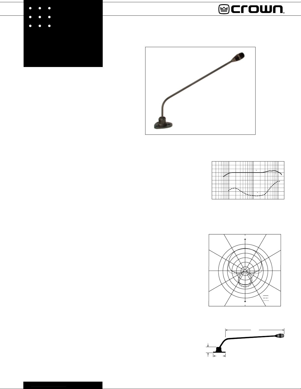
LM-200A
he Crown® LM-200A is a profes
sional-quality, supercardioid electret
T
con-denser microphone designed for
use on lecterns, pulpits, or similar applications.
The microphone is easily installed with
wood screws or bolts. As it is swiveled to
the desired position, adjustment is noisefree, unlike with some conventional gooseneck microphones. Swivel motion is limited
to prevent cable damage. The LM-200A is
rugged, and is built to withstand daily abuse.
Because of its supercardioid pickup pattern,
the LM-200-A rejects background noise and
room reverberation, and improves gainbefore-feedback, more than a microphone
with a cardioid pattern.
The LM-200A has a smooth, wide-range
frequency response for natural reproduction
of the voice. Low frequencies are filtered out
to reduce pickup of lectern thumps, room
rumble, etc.
The included wire-screen grille has a twostage pop filter to reduce pickup of explosive breath sounds. An external foam
windscreen is supplied for extra pop rejection or for outdoor use. The base features
built-in shock mounts that attenuate handling noise and lectern thumps.
The microphone output is balanced, low
impedance, which allows long cable runs
without hum pickup or high-frequency loss.
Two finishes are available: black (model LM200AP) or brown (model LM-200AB).
Operating Instructions
The LM-200A comes in two parts: a microphone/swivel mount and an electronics
module.
Mounting:
1. Using the swivel mount as a template,
mark and drill three 1/8"-diameter holes for
the mounting screws (supplied).
Your pulpit might already have mounting
holes that fit the LM-200A. If these holes are
oriented opposite to those in the LM200A base simply remove the Philips panhead screw from the side of the base and
align the holes in the base with those in the
pulpit. Then, rotate the boom arm 180°,
reinsert the pan-head screw into the hole in
the side of the base and mount the base to
the pulpit.
2. Drill a 1/2-inch diameter hole in the lec-
SUPERCARDIOID CONDENSER
LECTERN MICROPHONE
Specifications
Type: Unidirectional condenser.
Element: Electret condenser.
Frequency response (typical): 80 Hz to 15,000 Hz. See
Fig. 1.
Polar pattern: Supercardioid. See Fig. 2.
Impedance: 150 ohms, balanced. Recommended
minimum load impedance 1000 ohms.
Open-circuit sensitivity: 6.0 mV/Pa* (-44.5 dBV/Pa).
Power sensitivity: -42 dB re 1 mW/Pa*.
Equivalent noise level: 28 dB SPL typical (0 dB=.0002
dyne/cm2), A-weighted.
S/N ratio: 66 dB at 94 dB SPL.
Maximum SPL: 120 dB SPL for 3% THD.
Polarity: Positive pressure on the diaphragm produces a
positive voltage on output terminal 2 with respect to
output terminal 3 on the electronics module.
Operating voltage:
Option 1: Phantom power, 9 to 48 volts DC, positive
voltage on output terminals 2 and 3 with respect to
output terminal 1 on the electronics module. Option 2:
9-24 volts DC, supplied by a separate AC/DC adapter
such as Crown PS-24. You select this powering
option by moving jumpers inside the electronics
module (see Operating Instructions).
Current drain: 1.4 mA.
Materials: Polycarbonate swivel mount and ball, steel
tube and grille, steel electronics module.
Finish: Black (LM-200AP) or brown (LM-200AB).
Cable: Grey, permanently attached, 2-conductor shielded
cable, terminated with spade lugs for connection to
electronics module. Six-and-one-half feet long from
swivel mount to spade lugs.
Weight (microphone and cable only): 10.2 ounces
(288.3 grams).
Weight (microphone, cable, and electronics module):
18.2 ounces (515 grams).
Dimensions: See Figs. 3a, 3b and 3c. All dimensions in
inches.
Included accessories: Foam windscreen, Crown part no.
WS-8.
Optional accessories: PH-1A phantom power supply
(1 ch., battery or AC adaptor powered), PH-4B
phantom power supply (4 ch., AC powered).
Fig. 1
Frequency Response
+15
+10
+5
dB 0
–5
–10
–15
–20
–25
–30
–35
20 100 1K
Frequency in Hz
Fig. 2
Horizontal-Plane Polar Response
330˚
300˚
270˚
240˚
210˚
Fig. 3a
1.15"
Swivel Mount
3.15"
FRONT
REAR
180˚
0 ,6"
125,2'
10K
0˚
-0
-5
-10
-15
-20
16.00"
30˚
150˚
500-5000 Hz
200 Hz
10,000 Hz
Microphone
60˚
90˚
120˚
Page 2
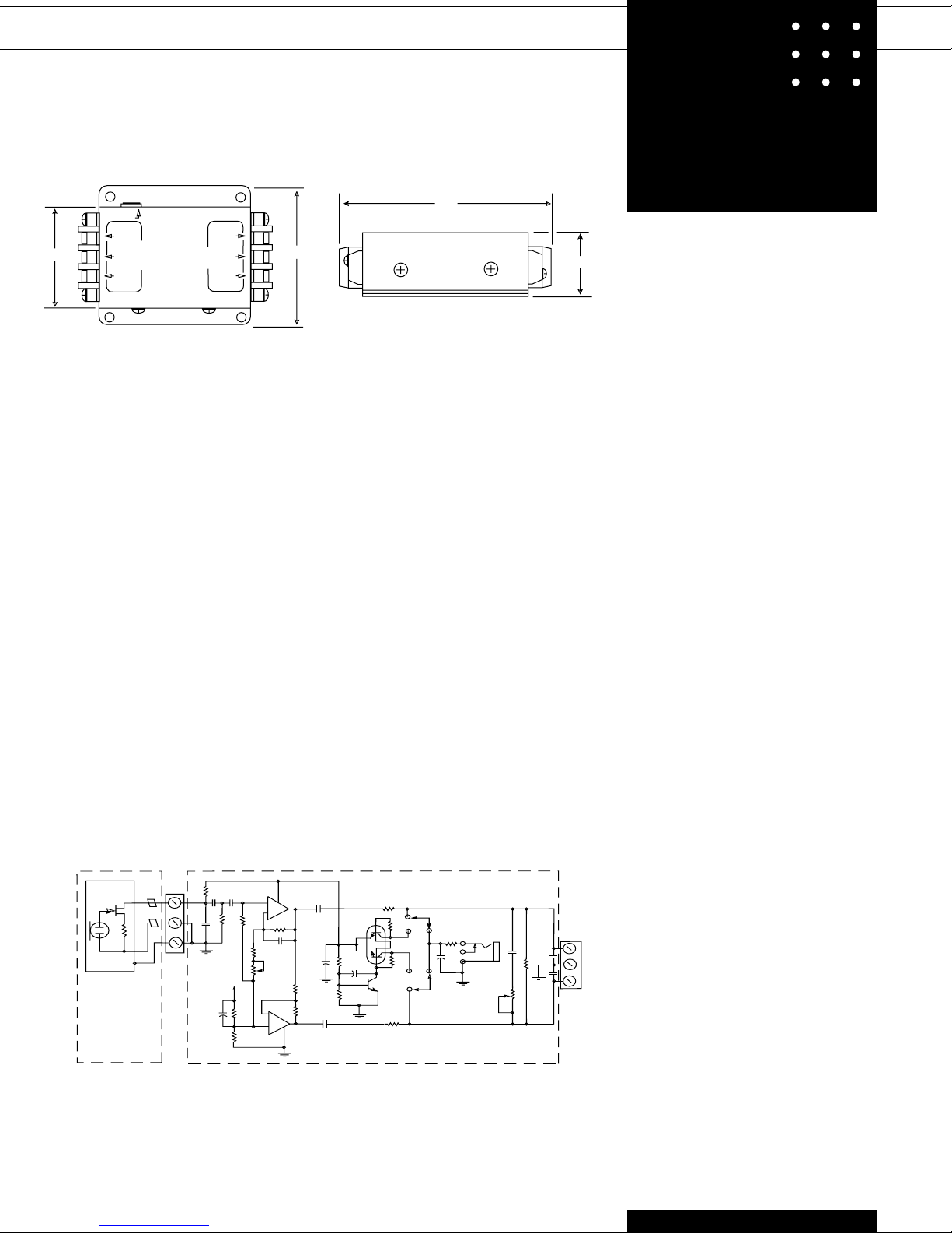
Fig. 3b
_
+
12-24 VDC
W
2.00
AUDIO
AUDIO
GND
SUPER CARDIOID
MICROPHONE
MIC OUT
MIC IN
BLACK
SHIELD
HITE
tern top in the center of the three 1/8"-diameter holes. The microphone cable will run
through this hole. Alternatively, you can run
the cable along the top of the lectern and
down the side, so that no cable hole is
needed.
3. Using the supplied mounting screws and
washers, screw the swivel mount to the
lectern top. Screw down the mounting
screws securely. Do not overtighten. Some
slight wobbling of the base is normal when
the microphone is moved.
4. If you want unlimited microphone rotation,
remove the set screw in the base of the
microphone. Caution: If the boom arm is
rotated fully around, it may twist the cable
and break it.
5. Using woodscrews, mount the base plate
of the electronics module inside the lectern
or wherever desired. You can remove the
module cover by undoing the screws on the
side of the module.
Powering: The LM-200A is factory set for
use with 9-48 volt phantom power. To
change to 12-24 volt DC power, see instructions inside electronics module cover.
Connections: Connect the LM-200A cable
2.80
Fig. 3c
3.90
1.25
spade lugs, and your microphone cable, to
the electronics module as shown in Figure
3b.
Warning: Do not lubricate the microphone
swivel mount, as it may lose its friction
and not stay in place. Use only mild soap
and water to clean the microphone.
Tension Adjustment: If the swivel becomes
loose, remove the swivel mount from the
lectern and look under the mount. You’ll see
a ring with two holes 180 degrees apart.
Place the tips of a needlenose pliers in these
holes, and rotate the ring clockwise until the
swivel is sufficiently tight. Remount the unit.
Architects’ and Engineers’ Specifications
The microphone shall be the Crown model
LM-200A or equivalent. The microphone
shall be a supercardioid electret-condenser
type with a built-in shock-mounted swivel
mount and pop-filter grille. Permanently
attached to the microphone shall be a 61/2', two-conductor shielded cable that
connects to a supplied electronics module.
The microphone shall be powered from 9 to
48 volts phantom powering or 9-24 volts
DC. Frequency response shall be uniform
from 80 Hz to 15,000 Hz. Open-circuit sensitivity shall be 6.0 mV/Pa. Impedance shall be
LM-200A
150 ohms balanced. Maximum SPL capability shall be 120 dB SPL at 3% THD. Equivalent noise shall be 28 dBA typical (0 dB
=.0002 dyne/cm
Models ending in “P” shall be black finish;
models ending in “B” shall be brown finish.
The Crown Model LM-200AP or LM-200AB
microphone is specified.
Microphone Warranty
Crown professional microphones are guaranteed unconditionally against malfunction
from any cause for a period of three years
from date of original purchase. See enclosed
warranty sheet for additional information.
Service
If the unit fails to work, replace or repair any
additional mic cables, or check the power
supply. If service is required, return both the
microphone and its interface in their original
packaging to Crown Service Department,
Plant 2SW, 1718 West Mishawaka Road,
Elkhart, IN 46517. For further assistance or
technical support call 800-342-6939.
At the factory, the electronics module is
matched to your particular microphone’s
frequency response. If you determine that
just the microphone or the module needs
service, send both anyway. Then we can
match your electronics to your microphone. The serial number is on both
pieces.
2
).
AUDIO
FB1
FB2
MICROPHONE
MICROPHONE HOUSING
Jumpers J1 and J2 shown in phantom mode at 1 and 4.
For 12-24V DC operation, move J1 and J2 to positions 2 and 3.
SHIELD
CAPSULE
2.2K
B
+
GND
P1
.1µF
.1µF
.001
µF
.47µF
3
2
20K
20K
2.2K
10K
B
+
6
+
100K
5
100K
IC1
8
+
1
_
47K
.047
µF
2200µF
4.7K
4.7K
IC2
_
7
4
+
22µF
50V
16V
22µF
ELECTRONICS MODULE
LM-200A Schematic
220
1
Q2
3
5
+
90.9K
7
+
2.2µF
Q1
6.8K
50V
J1
1
100K
2
2
6
100K
220
1K
+
47µf
50v
3
J2
4
.1µF
270
500
2
AUDIO
+
.1µF
1
.1µF
GND
_
AUDIO
3
P2
@crown
®
Crown International, Inc.
P.O. Box 1000
Elkhart, IN 46515-1000
TEL: 219-294-8000
FAX: 219-294-8FAX
©
1997 Crown International, Inc.
Specifications subject to change without prior notice.
®
Crown
is a registered trademark of Crown Interna-
tional, Inc.
8/97 125137-1
 Loading...