

Crown I-Tech I-T5000 HD, I-Tech I-T9000 HD, I-Tech I-T2000 HD Operation Manual
Obtaining Other Language Versions: To obtain information in anot her language about th e
use of this product, plea se contact your local Crown Distr ibutor. If yo u need as sistance locating
your local distributor, please contact Crown at 574-294-8000.
This manual does not include all of the details of design, production, or variations of the
equipment. Nor does it cover ever y possible situation which may arise during installation,
operation or maintenance.
The information provided in this manual was deemed accurate as of the publication date.
However, updates to this information may have occurred. To obt ain the latest version of this
manual, please visit the Crown website at www.crownaudio.com.
Trademark Notice: Crown, Crown Audio, and Amcron are registered trademarks of Crown
International. Other trademarks are the property of their respective owners. Later versions
of this manual and additional information about this product may be available at the Crown
website at www.crownaudio.com.
Some models may be exported under the name Amcron
®
©2011 by Crown Audio®, Inc., 1718 W. Mishawaka Rd., Elkhart, Indiana 46517-9439 U.S.A.
Telephone: 574-294-8000.
Models: I-T5000 HD, I-T9000 HD, I-T2000 HD
I-Tech HD Series Operation Manual
5009241 - 11/11

I-Tech HD Series Power Amplifiers I-Tech HD Series Power Amplifiers
page 2
page 3
Operation ManualOperation Manual
1. Read th ese instr uctions.
2. Keep th ese instr uctions.
3. Heed all w arnings.
4. Follow all in structio ns.
5. Do not use t his appara tus near wa ter.
6. Clean o nly with a dry c loth.
7. Do n ot block any vent ilation opening s. Install in ac cordance
with the manufacturer’s instructions.
8. Do not install ne ar any heat sou rces su ch as rad iators , heat
regist ers, st oves, or o ther ap parat us (inclu ding amp lifiers)
that produce heat.
9. D o not defeat th e safety pur pose of the pol arized or groun ding-t ype plug. A p olarized p lug has tw o blades wi th one wide r
than th e other. A gr ounding -typ e plug has t wo blad es and
a third gro unding pr ong. The w ide blad e or the thi rd prong
is provid ed for you r safet y. If the pr ovided pl ug does n ot fit
into your o utlet, cons ult an electr ician for repla cement of th e
obsolete outlet.
10. P rotec t the pow er cord fr om being w alked on o r pinche d,
part icularly at plug s, convenien ce recept acles, and th e point
where they exit from the apparatus.
11. Only use a tta chmen ts/ac cess ories sp ecifie d by the ma nufac turer.
12. Use o nly with a c art, s tand , tripod, b racke t, or
table s pecified by the m anufactu rer, or sold with
the app arat us. Whe n a cart is u sed, us e cauti on
when mo ving the c art/app aratus combi nation to
avoid inju ry from tip- over.
13. Un plug this a ppara tus durin g lightni ng storm s or when u nused for long periods of time.
14. Refer all s ervicin g to qualified s ervice p ersonne l. Servic ing is
requir ed when the app aratus has b een damage d in any way,
such as p ower-su pply cor d or plug is da mage d, liquid ha s
been sp illed or obj ects ha ve falle n into the a ppara tus, th e
appar atus ha s been e xpose d to rain or m oistur e, does n ot
opera te normally, or h as been dro pped.
15. Us e the mains p lug to discon nect the a pparat us from the m ains.
16. WARNING : TO REDUCE T HE RISK O F FIRE OR E LECTR IC
SHOCK , DO NOT EX POSE T HIS APPA RATUS T O RAIN O R
MOISTURE.
17. DO N OT EXPOSE T HIS EQUIPMEN T TO DRIPPING
OR SPL ASHING AN D ENSURE TH AT NO OBJECTS
FILLE D WITH L IQUIDS, S UCH AS VAS ES, ARE
PLACE D ON THE EQUIP MENT.
18. T HE MAIN S PLUG OF T HE POW ER SUPPLY CO RD SHA LL
REMA IN READILY OP ERABLE .
TO PRE VENT ELECT RIC SHOCK DO NO T REMOVE
TOP OR BOT TOM COV ERS. N O USER SE RVICE ABLE PA RTS INSIDE . REFER SE RVICING TO Q UALIFIED SERVICE PERSONNEL.
TO COMPLETELY DISCONNECT THIS EQUIPMENT F ROM THE AC MAI NS, DISCONN ECT THE
POWE R SUPPLY CORD PLU G FROM THE AC RE CEPTACL E. THE MA INS PLU G OF THE P OWER
SUPPLY COR D SHALL REM AIN READ ILY OPERABL E.
WATCH FOR THESE SYMBOLS:
The ligh tning bolt tr iangle is use d to alert t he user to
the risk o f electric sh ock.
The excl amati on point tr iangle is u sed to al ert the
user to im port ant ope rating o r mainte nanc e instructions.
IMPORTANT
XLS Se ries amplifie rs require Cl ass 2 outpu t wiring.
MAGNETIC FIELD
CAUTI ON! Do not lo cate s ensiti ve high- gain equ ipment s uch as
pream plifier s or tape d ecks dir ectly a bove or b elow the u nit. Be cause t his amplifier h as a high power d ensity, it ha s a strong mag netic fi eld which can ind uce hum into unsh ielded devic es that are
locat ed nearb y. The field is st rongest ju st above an d below the u nit.
If an equi pment r ack is us ed, we re comme nd loca ting the
amplifier(s) in the bottom of the rack and the preamplifier or
other s ensitive eq uipment at th e top.
FCC COMPLIANCE NOTICE
This device complies with part 15 of the FCC rules. Operation is subject to the following two conditions: (1) This device may not cause
harmful interference, and (2) this device must accept any interference
received, including interference that may cause undesired operation.
CAUTION: Changes or modifications not expressly approved by the
party responsible for compliance could void the user’s authority to
operate the equipment.
NOTE: This equipment has been tested and found to comply with
the limits for a Class B digital device, pursuant to part 15 of the FCC
Rules. These limits are designed to provide reasonable protection
against harmful interference in a residential installation. This equipment generates, uses, and can radiate radio frequency energy and,
if not installed and used in accordance with the instruction manual,
may cause harmful interference to radio communications. However,
there is no guarantee that interference will not occur in a particular
installation. If this equipment does cause harmful interference to radio or television reception, which can be determined by turning the
equipment off and on, the user is encouraged to try to correct the
interference by one or more of the following measures:
• Reorient or relocate the receiving antenna.
• Increase the separation between the equipment and receiver.
• Connect the equipment into an outlet on a circuit different from
that to which the receiver is connected.
• Consult the dealer or an experienced radio/TV technician for help.
Important Safety Instructions
DECLARATION OF CONFORMITY
European Representative’s Name and Address:
David J. Budge
10 Harvest Close
Yateley
GU46 6YS
United Kingdom
Equipment Type: Commercial Audio Power Amplifiers
Family Name: I-Tech HD
Model Names: I-T5000 HD, I-T9000 HD, I-T12000 HD
EMC Standards:
EN 55103-1:1997 Electromagnetic Compatibility – Product Family Standard for Audio, Video, Audio-Visual and Entertainment
Lighting Control Apparatus for Professional Use, Part 1: Emissions
EN 55103-1:1997 Magnetic Field Emissions-Annex A @ 10 cm and 1 M
EN 61000-3-2:2005 & Amd 1: 2008 Limits for Harmonic Current Emissions (equipment input current ≤16A per phase)
EN 61000-3-3:1998 Limitation of Voltage Fluctuations and Flicker in Low-Voltage Supply Systems Rated Current ≤16A
EN 55022:2006 Limits and Methods of Measurement of Radio Disturbance Characteristics of ITE: Radiated, Class B Limits;
Conducted, Class B
EN 55103-2:1997 Electromagnetic Compatibility – Product Family Standard for Audio, Video, Audio-Visual and Entertainment
Lighting Control Apparatus for Professional Use, Part 2: Immunity
EN 61000-4-2:2001 Electrostatic Discharge Immunity (Environment E2-Criteria B, 4k V Contact, 8k V Air Discharge)
EN 61000-4-3:2006 Radiated, Radio-Frequency, Electromagnetic Immunity (Environment E2, Criteria A)
EN 61000-4-4:2007 Electrical Fast Transient/Burst Immunity (Criteria B)
EN 61000-4-5:2006 Surge Immunity (Criteria B)
EN 61000-4-6:2006 Immunity to Conducted Disturbances Induced by Radio-Frequency Fields (Criteria A)
EN 61000-4-11:2001 Voltage Dips, Short Interruptions and Voltage Variation
Safety Standard:
IEC 60065: 2001: 7Ed & Amd 1: 2005 Safety Requirements - Audio Video and Similar Electronic Apparatus
I certify that the product identified above conforms to the requirements of the EMC Council Directive 89/336/EEC as amended by
92/31/EEC, and the Low Voltage Directive 73/23/EES as amended by 93/68/EEC.
Issued By: Harman International.
1718 W. Mishawaka Rd.
Elkhart, IN 46517 U.S.A.
Sue Whitfield
574-294-8289
Sue.Whitfield@harman.com
FOR COMPLIANCE
QUESTIONS ONLY:
Signed _____________________________
Terry Davenport
Director of Manufacturing
Date of Issue: November 1, 2008
Due to line current harmonics, we recommend that you contact your supply authority before connection.
I-Tech HD Series Power Amplifiers I-Tech HD Series Power Amplifiers
page 4
page 5
Operation ManualOperation Manual
Welcome
This is the Crown® I-Tech HD Series offers amazing power, light weight and ease of use for touring sound
applications. Unlike other amplifiers, it includes onboard high-definition DSP, an LCD control screen, and a builtin network connection.
Modern power amplifiers are sophisticated pieces of engineering capable of producing extremely high power
levels. They must be treated with respect and correctly installed if they are to provide the many years of reliable
service for which they were designed.
In addition, I-Tech Series amplifiers include a number of features which require some expla nation before they can
be used to their maxi mum advantage.
Please take the time to study this manual so that you can obtain the best possible service from your amplifier.
Get Started
Features
1. Global Power Supply with PFC (Power Fac tor Correction) works anywhere in the world.
2. High power density, up to 8000 watts in a 2U chassis.
3. Highest output voltage in the industry (200V peak) provides clean transient peaks.
4. 3rd-generation patented Class I (BCA®) cir cuitry couples power
efficiently to the load and provides low AC current draw.
5. Onboard high-definition DSP with 24-bit, 192 kHz Cirrus Logic SHARC A/D
and D/A converters. Advanced IIR filters and linear-phase FIR filters.
6. Pushbutton presets simplify setup. Custom presets for various loudspeakers can be down loaded.
7. AES/EBU digital audio input.
8. EtherCon® Ethernet con nector for HiQnet™ control or CobraNet digital audio transport. This “Single
Plug” connection allows HiQnet protocol and CobraNet digital audio through the same CAT 5 cable.
9. Analog and digital thru connectors.
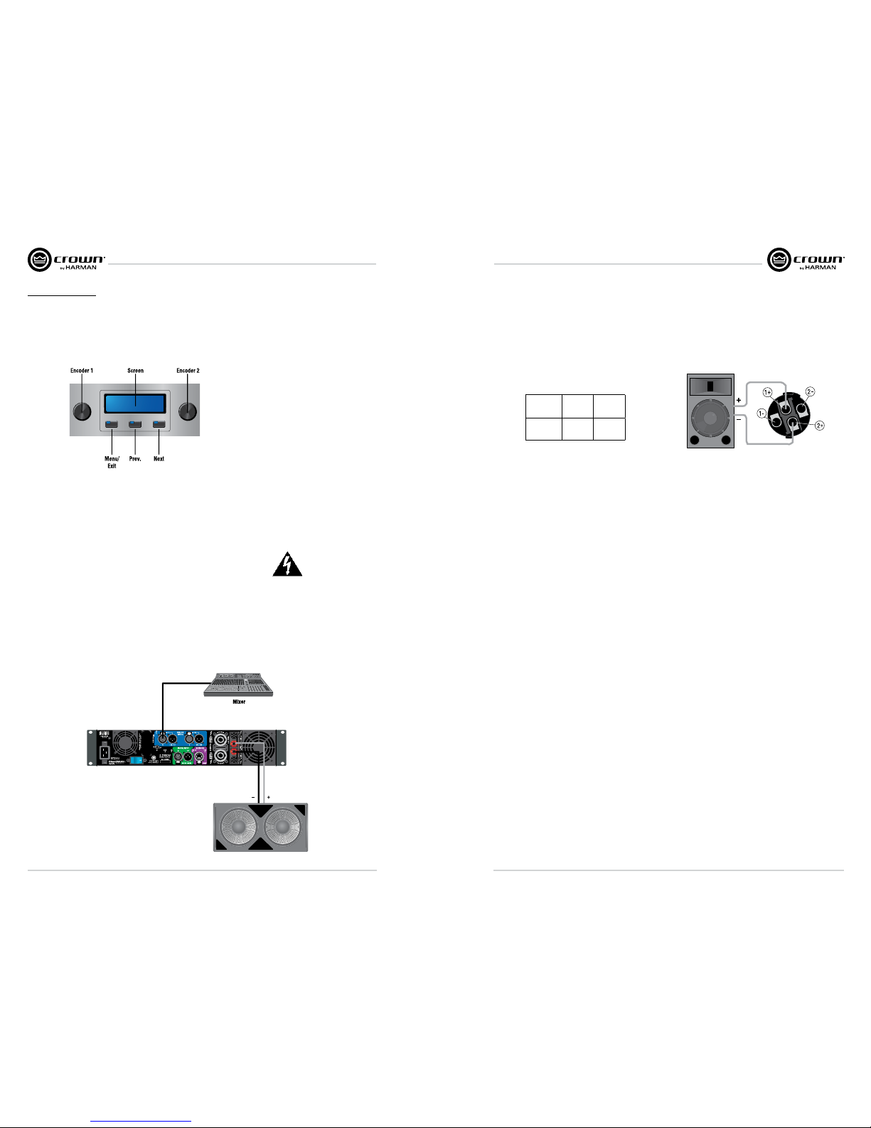
10. LCD Control Screen is used to adjust the amplifier’s attenuation and muting, configure the amp, set
up and view error monitoring, and recall DSP presets to reconfigure the amp for various applications.
11. Comprehensive array of indicators provide accurate diagnostics: Power, Data, along with Ready,
Signal, Clip, Thermal and Fault for each channel.
12. AC mains indicator in power switch glows green when AC power is present.
13. Front-panel USB connector accepts a USB drive to transfer presets from the drive to the
amplifier DSP, and vice versa.
14. Light weight due to aluminum chassis, spe cial internal construction and switching power supply.
15. Thermal management controller and two dis crete thermal zones with variable-speed fans,
forced-air cooling.
16. Advanced protection circuitry guards against: shorted outputs, DC, mismatched loads,
general overheating, under/over volt age, high-frequency overloads and internal faults.
17. Three-Year, No-Fault, Fully Transferable Warranty completely protects your investment and guarantees its
specifications.
Unpack and Install Your Amplifier
When Please unpack and inspect your amplifier for any damage that may have occurred during transit. If damage
is found, notify the transpor tation company immediately. Only you can ini tiate a claim for shipping damage.
Crown will be happy to help as needed. Save the shipping carton as evidence of damage for the shipper’s
inspection.
We also recommend that you save all packing materials so you will have them if you ever need to transport the
unit. Never ship the unit without the factory pack.
YOU WILL NEED (not supplied):
1. Input wiring cables
2. Output wiring cables
3. Ethernet cables
4. Rack for mounting amplifier (or a stable surface for stacking)
WARNING: Before you start to set up your amplifier, make sure you read and observe
the Important Safety Instruc tions found at the beginning of this
manual.
CAUTION: Before you begin, make sure your amplifier is disconnected from the power
source, with the power switch in the “off” position and all level controls turned
completely down (counterclock wise).
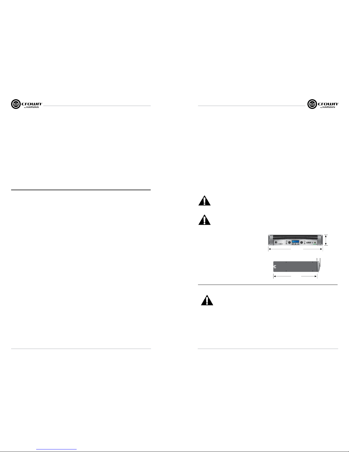
Use a standard 19-inch (48.3 cm) equipment rack
(EIA RS-310B).
You may also stack amps without using a
cabinet.
NOTE: When transporting, amplifiers should be
supported at both front and back.
Setup
1.5 In.
3.8 cm
3.5 In.
8.9 cm
16.2 In.
41.1 cm
48.3 cm
19 In.
Magnetic Field
CAUTION! Do not locate sensitive high-gain equipment such as preamplifiers or tape decks directly
above or below the unit. Because this amplifier has a high power density, it has a strong magnetic
field which can induce hum into unshielded devices that are located nearby. The field is strongest
on the right side and right bottom of the amplifier (facing the amplifier).
If an equipment rack is used, we recommend locating sensitive equipment at least 20 cm
(8 inches) away from the amplifier.
When using an equipment rack, mount units directly on top of each other. Close any open spaces in rack with
blank panels. DO NOT block front or rear air vents. The side walls of the rack should be a minimum of two inches
(5.1 cm) away from the amplifier sides, and the back of the rack should be a minimum of four inches (10.2 cm)
from the amplifier back panel.
I-Tech HD Series Power Amplifiers I-Tech HD Series Power Amplifiers
page 6
page 7
Operation ManualOperation Manual
Wire Inputs and Outputs
Wiring basics
• Always use shielded wire for input wiring. The higher the density of the shield (the
outer conductor) the better. Spiral wrapped shield is not recom mended.
• When using unbalanced lines keep the cables as short as possible.
Avoid lengths greater than 10 feet (3 meters).
• Do not run the audio input cables together with the high-level wiring such as loudspeaker wires or
AC cords. (This lessens the chance of hum and noise being induced into the input cables.)
• Turn the entire sound system off before changing any connections. Crown is not liable
for damage incurred when any transducer or compo nent is over driven.
THE CHANNEL 2 INPUT IS IGNORED by default in Bridge Mono mode. It can be summed using the
input source selector and used instead of Channel 1.
For additional information on audio input wiring please refer to the Crown Amplifier Application Guide available
online at www.crownaudio.com. It contains helpful information on
preventing unwanted subsonic frequen cies, radio frequency interference,
ground loops, and feedback oscillation.
When using network connections, pass the CAT 5 cable five times
through a ferrite core, available from Crown Audio Inc. This is to ensure
compliance with emission regulations.
Connecting to AC Mains
WARNING: The third (ground) prong of the supplied AC power cord connector is a
required safety feature. Do not attempt to disable this ground connection by using an
adapter or other methods.
Amplifiers don’t create energy. The AC mains voltage and current must be sufficient to deliver the power you
expect. You must operate your amplifier from an AC mains power source with not more than a 10% variation
above or a 15% variation below the amplifier’s specified line voltage range and within the specified frequency
requirements (indicated on the amplifier’s back panel label). If you are unsure of the output voltage of your AC
mains, please consult your electrician.
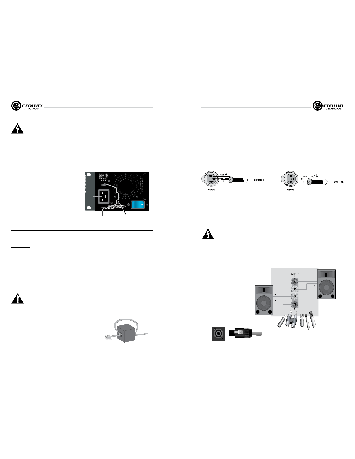
Packed with your I-Tech amplifier is a clip that retains the power cord so it can’t pull out accidentally.
1. Locate the clip in a bag in the I-Tech packing carton.
2. Locate the IEC power connector on the back
of the amplifier. Above and below that
connector are two slots. Stretch the ends of
the clip and insert them into the slots.
3. Plug the power cord all the way into the
amplifier IEC power connector.
4. Pull the clip to the left and snap it onto the
power cord.
IEC Power Connector
Slot
Slot
Clip
Choose Input Wire and Connectors
Crown recommends using pre-built or professionally wired, bal anced line (two-conductor plus shield), 22-24
gauge cables and connectors. Use 3-pin male XLR connectors.
Unbalanced line may also be used but may result in noise over long cable runs.
The image below on the left shows connector pin assignments for balanced analog wiring or AES/EBU digital
wiring. The use of standard analog cable with AES/EBU will result in diminished performance. For best results,
110 ohm shielded twisted-pair cable for AES/EBU signals is highly recommended. The image below on the right
shows connector pin assignments for unbalanced analog wiring.
NOTE: Custom wiring should only be performed by qualified per sonnel.
Choose Output Wire and Connectors
Crown recommends using pre-built or professionally wired, high-quality, two- or four-conductor, heavy gauge
speaker wire and connectors. Use Class 2 output wiring. You may use a 4-pole Speakon
®
connector or banana
plugs, spade lugs, or bare wire for your output connectors. To prevent the possibility of short circuits, wrap or
otherwise insulate exposed loudspeaker cable connectors.
CAUTION – SHOCK HAZARD: Potentially lethal voltages exist at the output connectors
when the amplifier is turned on and is passing a signal.
Using the guidelines below, select the appropriate size of wire based on the distance from amplifier to speaker.
Distance Wire Size
up to 25 ft. 16 AWG
26-40 ft. 14 AWG
41-60 ft. 12 AWG
61-100 ft. 10 AWG
101-150 ft. 8 AWG
151-250 ft. 6 AWG
CAUTION: Never use shielded
cable for output wiring.
I-Tech HD Series Power Amplifiers I-Tech HD Series Power Amplifiers
page 8
page 9
Operation ManualOperation Manual
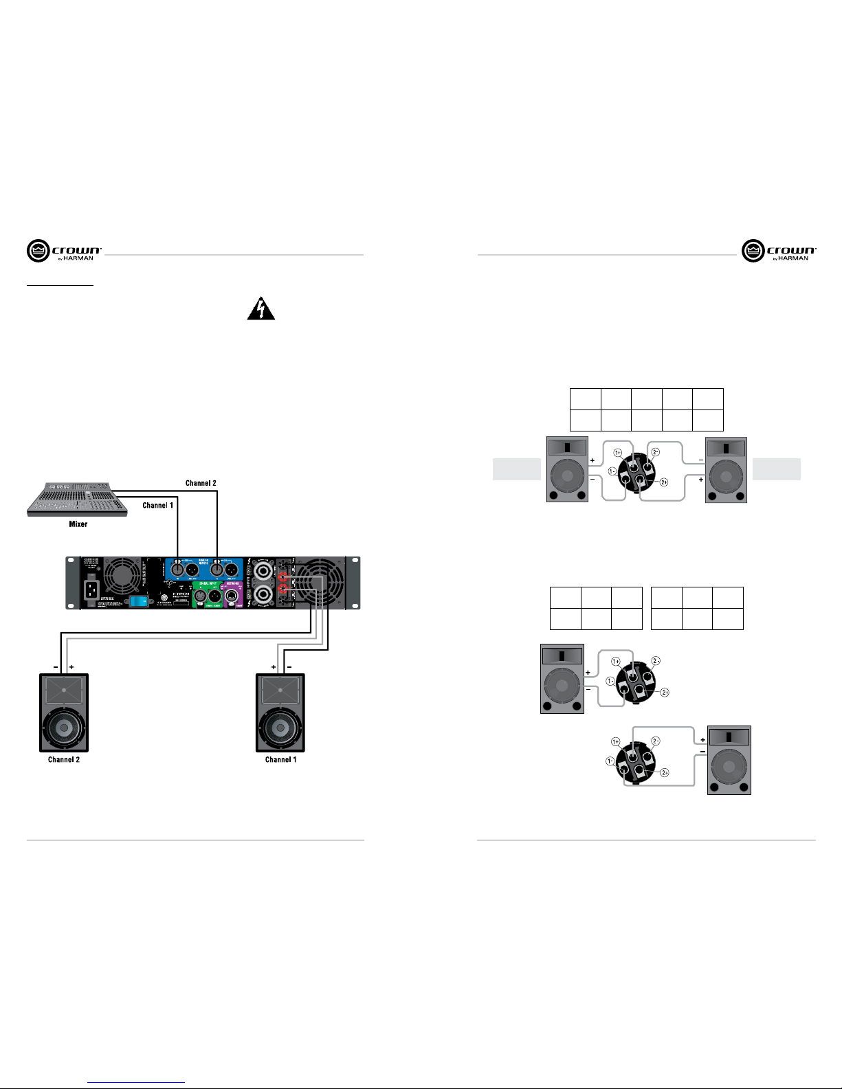
Stereo Mode Wiring
Typical input and output wiring is shown in image below.
IMPORTANT: Turn off the amplifier and unplug its power cord.
INPUTS: Choose one of these options:
• Connect analog input wiring for both channels.
• Connect an AES/EBU digital signal to the AES/EBU connector.
OUTPUTS: Maintain proper polarity (+/–) on output connectors. Use Class 2 output wiring.
The image below shows how to wire stereo speakers to the binding posts. Con nect Channel 1 loudspeaker’s
positive (+) lead to Channel 1 positive (red) terminal of amp; repeat for negative (–). Repeat Channel 2 wiring as
for Channel 1.
To wire stereo speakers to the Speakon® connectors, use one of these methods:
Method 1: Wire one Speakon® cable connector to two speakers. Insert the Speakon® cable connector into the
amplifier’s top Speakon® connector.
Method 2: Plug the Channel 1 speaker into the Channel 1 (top) Speakon® connector, and plug the Channel 2
speaker into the Channel 2 (bottom) Speakon® connector.
PIN 1+ 1– 2+ 2–
CH 1+ 1– 2+ 2–
Stereo Wiring Method 1: Use Top Speakon® Only
Method 1
Method 2
Channel 1
Loudspeaker
Channel 2
Loudspeaker
Channel 1
Loudspeaker
Channel 2
Loudspeaker
Top Speakon
(Channel 1)
Bottom
Speakon
(Channel 2)
Stereo Wiring Method 2: Use Both Speakon®s
PIN 1+ 1–
CH 2+ 2–
PIN 1+ 1–
CH 1+ 1–
Top Speakon
Bottom Speakon
I-Tech HD Series Power Amplifiers I-Tech HD Series Power Amplifiers
page 10
page 11
Operation ManualOperation Manual
Bridge-Mono Mode
Overview: Turn on the amp, enable Bridge-Mono mode using the LCD Control Screen, turn off the amp, wire it,
and turn it back on.
1. Be sure that no cables are connected to the amplifier. Turn on the front-panel power switch. The LCD
Control Screen will light up.
2. Under the LCD Control Screen, press the Menu/Exit button. Press the Next button until you see OUTPUT
MODE on the screen. If N/A is displayed, OUTPUT MODE is locked via software. If LOCKOUT is displayed,
all the LCD screens are locked via software.
Press an Encoder knob to select BRIDGE MONO. Press the knob again to confirm your choice. Press
Menu/Exit. Turn down both level controls (Encoders) until you reach maximum attenuation.
3. IMPORTANT: Turn off the amplifier and unplug its power cord.
INPUTS: There are three ways to connect an input signal to the amplifier:
• Connect an analog signal source to the Channel-1 amplifier input.
• Connect an AES/EBU digital signal source to the Digital Input IN connector.
NOTE: Crown provides a reference of wiring pin assignments for commonly used connector types in the Crown
Amplifier Application Guide available at
www.crownaudio.com.
OUTPUTS: Use Class 2 output wiring. There are two ways to wire the amplifier output connectors for BridgeMono mode:
NOTE: In Bridge-Mono mode, the
Channel 1 Level control sets the
level; the Channel-2 Level control is
defeated. All Channel-2 objects and
controls are hidden and disabled.
Menu/Exit Prev Next
1. Wire the speaker across the red binding post of each channel. Do not use the black binding posts when
operating in Bridge-Mono mode.
2. Wire the speaker only to the top Speakon® connector as shown in the table below.
PIN 1+ 2+
SPKR
+ –
Top Speakon® Wiring for Bridge-Mono
I-Tech HD Series Power Amplifiers I-Tech HD Series Power Amplifiers
page 12
page 13
Operation ManualOperation Manual
Protecting Your Speakers
It’s wise to avoid clipping the amplifier signal. Not only does clipping sound bad, it can damage high-frequency
drivers. To prevent clipping, use System Architect software’s Level Max suite to enable or display the peak voltage
limiter and average power limiter in your amplifier’s built-in DSP. That way, no matter how strong a signal your
mixer produces, the amplifier output will not clip. Set the limiter threshold so that mixer signals above 0 dB or 0
VU on the mixer meters do not quite drive the amplifier into clipping.
Also, avoid sending strong subsonic signals to the amplifier. High-level, low-frequency signals from breath pops
or dropped micro phones can blow out drivers. To prevent subsonic signals, use one of these methods:
• Insert a highpass filter between mixer output and amplifier input (or between mixer and limiter).
• Use the I-Tech’s onboard DSP to set up a highpass filters.
• Switch in highpass filters at your mixer. Set the filter to as high a fre quency as possible that does not affect
your program. For example, try 35 Hz for music and 75 Hz for speech. On each mixer input channel, set the
filter frequency just below the lowest fundamental frequency of that channel’s instrument.
Operation
Startup Procedure
When first turning on your amplifier, follow the procedures in the Quick-Start Guide on page 4 (stereo) or page 5
(bridge-mono).
If you ever need to make any wiring or installation changes, don’t for get to disconnect the power
cord.
For help with determining your system’s optimum gain structure (sig nal levels) please refer to the
Crown Amplifier Application Guide, available online at www.crownaudio.com.
Precautions
Your amplifier is protected from internal and external faults, but you should still take the following
precautions for optimum performance and safety:
1. Before use, your amplifier first must be configured for proper operation, including input and output wiring
hookup. Improper wiring can result in serious operating difficulties. For information on wiring and
configuration, please consult the Setup section of this manual or, for advanced setup techniques, consult
Crown’s Amplifier Application Guide available online at
www.crownaudio.com.
2. Use care when making connections, selecting signal sources and controlling the output level. The load you
save may be your own!
3. Do not short the ground lead of an output cable to the input signal ground. This may form a ground loop and
cause oscillations.
4. WARNING: Never connect the output to a power supply, battery or power main.
Electrical shock may result.
5. Tampering with the circuitry, or making unauthorized circuit changes may be hazardous and
invalidates all agency listings.
6. Do not operate the amplifier with the red Clip LEDs constantly flashing.
7. Do not overdrive the mixer, which will cause clipped signal to be sent to the amplifier. Such signals will be
reproduced with extreme accuracy, and loudspeaker damage may result.
8. Do not operate the amplifier with less than the rated load imped ance. Due to the amplifier’s output protection,
such a configura tion may result in premature clipping and speaker damage.
9. CAUTION – SHOCK HAZARD: Potentially lethal voltages exist at the output connectors when the
amplifier is turned on and is passing a signal.
Remember: Crown is not liable for damage that results from overdriv ing other system components.
 Loading...