

Page 1
Obtaining Other Language Versions: To obtain information in anot her language about th e
use of this product, plea se contact your local Crown Distr ibutor. If yo u need as sistance locating
your local distributor, please contact Crown at 574-294-8000.
This manual does not include all of the details of design, production, or variations of the
equipment. Nor does it cover ever y possible situation which may arise during installation,
operation or maintenance.
The information provided in this manual was deemed accurate as of the publication date.
However, updates to this information may have occurred. To obt ain the latest version of this
manual, please visit the Crown website at www.crownaudio.com.
Trademark Notice: Crown, Crown Audio, and Amcron are registered trademarks of Crown
International. Other trademarks are the property of their respective owners. Later versions
of this manual and additional information about this product may be available at the Crown
website at www.crownaudio.com.
Some models may be exported under the name Amcron
®
©2011 by Crown Audio®, Inc., 1718 W. Mishawaka Rd., Elkhart, Indiana 46517-9439 U.S.A.
Telephone: 574-294-8000.
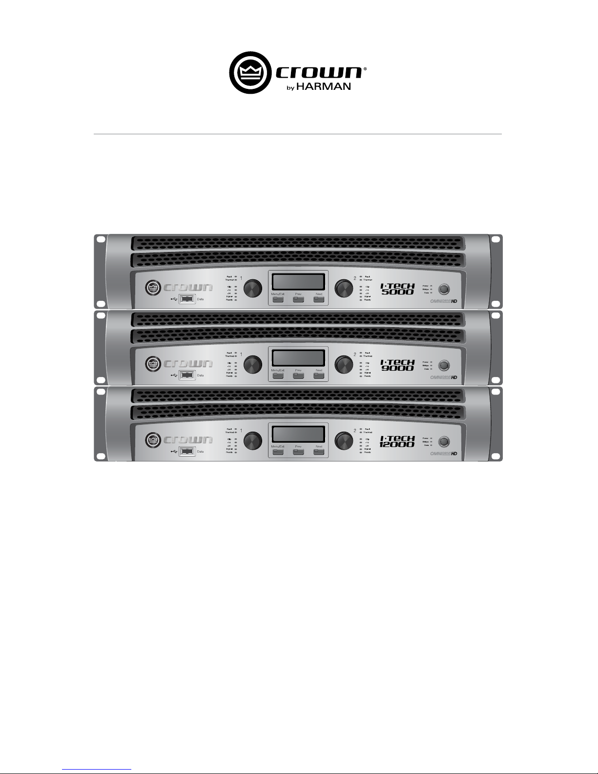
Models: I-T5000 HD, I-T9000 HD, I-T2000 HD
I-Tech HD Series Operation Manual
5009241 - 11/11
Page 2

I-Tech HD Series Power Amplifiers I-Tech HD Series Power Amplifiers
page 2
page 3
Operation ManualOperation Manual
1. Read th ese instr uctions.
2. Keep th ese instr uctions.
3. Heed all w arnings.
4. Follow all in structio ns.
5. Do not use t his appara tus near wa ter.
6. Clean o nly with a dry c loth.
7. Do n ot block any vent ilation opening s. Install in ac cordance
with the manufacturer’s instructions.
8. Do not install ne ar any heat sou rces su ch as rad iators , heat
regist ers, st oves, or o ther ap parat us (inclu ding amp lifiers)
that produce heat.
9. D o not defeat th e safety pur pose of the pol arized or groun ding-t ype plug. A p olarized p lug has tw o blades wi th one wide r
than th e other. A gr ounding -typ e plug has t wo blad es and
a third gro unding pr ong. The w ide blad e or the thi rd prong
is provid ed for you r safet y. If the pr ovided pl ug does n ot fit
into your o utlet, cons ult an electr ician for repla cement of th e
obsolete outlet.
10. P rotec t the pow er cord fr om being w alked on o r pinche d,
part icularly at plug s, convenien ce recept acles, and th e point
where they exit from the apparatus.
11. Only use a tta chmen ts/ac cess ories sp ecifie d by the ma nufac turer.
12. Use o nly with a c art, s tand , tripod, b racke t, or
table s pecified by the m anufactu rer, or sold with
the app arat us. Whe n a cart is u sed, us e cauti on
when mo ving the c art/app aratus combi nation to
avoid inju ry from tip- over.
13. Un plug this a ppara tus durin g lightni ng storm s or when u nused for long periods of time.
14. Refer all s ervicin g to qualified s ervice p ersonne l. Servic ing is
requir ed when the app aratus has b een damage d in any way,
such as p ower-su pply cor d or plug is da mage d, liquid ha s
been sp illed or obj ects ha ve falle n into the a ppara tus, th e
appar atus ha s been e xpose d to rain or m oistur e, does n ot
opera te normally, or h as been dro pped.
15. Us e the mains p lug to discon nect the a pparat us from the m ains.
16. WARNING : TO REDUCE T HE RISK O F FIRE OR E LECTR IC
SHOCK , DO NOT EX POSE T HIS APPA RATUS T O RAIN O R
MOISTURE.
17. DO N OT EXPOSE T HIS EQUIPMEN T TO DRIPPING
OR SPL ASHING AN D ENSURE TH AT NO OBJECTS
FILLE D WITH L IQUIDS, S UCH AS VAS ES, ARE
PLACE D ON THE EQUIP MENT.
18. T HE MAIN S PLUG OF T HE POW ER SUPPLY CO RD SHA LL
REMA IN READILY OP ERABLE .
TO PRE VENT ELECT RIC SHOCK DO NO T REMOVE
TOP OR BOT TOM COV ERS. N O USER SE RVICE ABLE PA RTS INSIDE . REFER SE RVICING TO Q UALIFIED SERVICE PERSONNEL.
TO COMPLETELY DISCONNECT THIS EQUIPMENT F ROM THE AC MAI NS, DISCONN ECT THE
POWE R SUPPLY CORD PLU G FROM THE AC RE CEPTACL E. THE MA INS PLU G OF THE P OWER
SUPPLY COR D SHALL REM AIN READ ILY OPERABL E.
WATCH FOR THESE SYMBOLS:
The ligh tning bolt tr iangle is use d to alert t he user to
the risk o f electric sh ock.
The excl amati on point tr iangle is u sed to al ert the
user to im port ant ope rating o r mainte nanc e instructions.
IMPORTANT
XLS Se ries amplifie rs require Cl ass 2 outpu t wiring.
MAGNETIC FIELD
CAUTI ON! Do not lo cate s ensiti ve high- gain equ ipment s uch as
pream plifier s or tape d ecks dir ectly a bove or b elow the u nit. Be cause t his amplifier h as a high power d ensity, it ha s a strong mag netic fi eld which can ind uce hum into unsh ielded devic es that are
locat ed nearb y. The field is st rongest ju st above an d below the u nit.
If an equi pment r ack is us ed, we re comme nd loca ting the
amplifier(s) in the bottom of the rack and the preamplifier or
other s ensitive eq uipment at th e top.
FCC COMPLIANCE NOTICE
This device complies with part 15 of the FCC rules. Operation is subject to the following two conditions: (1) This device may not cause
harmful interference, and (2) this device must accept any interference
received, including interference that may cause undesired operation.
CAUTION: Changes or modifications not expressly approved by the
party responsible for compliance could void the user’s authority to
operate the equipment.
NOTE: This equipment has been tested and found to comply with
the limits for a Class B digital device, pursuant to part 15 of the FCC
Rules. These limits are designed to provide reasonable protection
against harmful interference in a residential installation. This equipment generates, uses, and can radiate radio frequency energy and,
if not installed and used in accordance with the instruction manual,
may cause harmful interference to radio communications. However,
there is no guarantee that interference will not occur in a particular
installation. If this equipment does cause harmful interference to radio or television reception, which can be determined by turning the
equipment off and on, the user is encouraged to try to correct the
interference by one or more of the following measures:
• Reorient or relocate the receiving antenna.
• Increase the separation between the equipment and receiver.
• Connect the equipment into an outlet on a circuit different from
that to which the receiver is connected.
• Consult the dealer or an experienced radio/TV technician for help.
Important Safety Instructions
DECLARATION OF CONFORMITY
European Representative’s Name and Address:
David J. Budge
10 Harvest Close
Yateley
GU46 6YS
United Kingdom
Equipment Type: Commercial Audio Power Amplifiers
Family Name: I-Tech HD
Model Names: I-T5000 HD, I-T9000 HD, I-T12000 HD
EMC Standards:
EN 55103-1:1997 Electromagnetic Compatibility – Product Family Standard for Audio, Video, Audio-Visual and Entertainment
Lighting Control Apparatus for Professional Use, Part 1: Emissions
EN 55103-1:1997 Magnetic Field Emissions-Annex A @ 10 cm and 1 M
EN 61000-3-2:2005 & Amd 1: 2008 Limits for Harmonic Current Emissions (equipment input current ≤16A per phase)
EN 61000-3-3:1998 Limitation of Voltage Fluctuations and Flicker in Low-Voltage Supply Systems Rated Current ≤16A
EN 55022:2006 Limits and Methods of Measurement of Radio Disturbance Characteristics of ITE: Radiated, Class B Limits;
Conducted, Class B
EN 55103-2:1997 Electromagnetic Compatibility – Product Family Standard for Audio, Video, Audio-Visual and Entertainment
Lighting Control Apparatus for Professional Use, Part 2: Immunity
EN 61000-4-2:2001 Electrostatic Discharge Immunity (Environment E2-Criteria B, 4k V Contact, 8k V Air Discharge)
EN 61000-4-3:2006 Radiated, Radio-Frequency, Electromagnetic Immunity (Environment E2, Criteria A)
EN 61000-4-4:2007 Electrical Fast Transient/Burst Immunity (Criteria B)
EN 61000-4-5:2006 Surge Immunity (Criteria B)
EN 61000-4-6:2006 Immunity to Conducted Disturbances Induced by Radio-Frequency Fields (Criteria A)
EN 61000-4-11:2001 Voltage Dips, Short Interruptions and Voltage Variation
Safety Standard:
IEC 60065: 2001: 7Ed & Amd 1: 2005 Safety Requirements - Audio Video and Similar Electronic Apparatus
I certify that the product identified above conforms to the requirements of the EMC Council Directive 89/336/EEC as amended by
92/31/EEC, and the Low Voltage Directive 73/23/EES as amended by 93/68/EEC.
Issued By: Harman International.
1718 W. Mishawaka Rd.
Elkhart, IN 46517 U.S.A.
Sue Whitfield
574-294-8289
Sue.Whitfi[email protected]
FOR COMPLIANCE
QUESTIONS ONLY:
Signed _____________________________
Terry Davenport
Director of Manufacturing
Date of Issue: November 1, 2008
Due to line current harmonics, we recommend that you contact your supply authority before connection.
Page 3
I-Tech HD Series Power Amplifiers I-Tech HD Series Power Amplifiers
page 4
page 5
Operation ManualOperation Manual
Welcome
This is the Crown® I-Tech HD Series offers amazing power, light weight and ease of use for touring sound
applications. Unlike other amplifiers, it includes onboard high-definition DSP, an LCD control screen, and a builtin network connection.
Modern power amplifiers are sophisticated pieces of engineering capable of producing extremely high power
levels. They must be treated with respect and correctly installed if they are to provide the many years of reliable
service for which they were designed.
In addition, I-Tech Series amplifiers include a number of features which require some expla nation before they can
be used to their maxi mum advantage.
Please take the time to study this manual so that you can obtain the best possible service from your amplifier.
Get Started
Features
1. Global Power Supply with PFC (Power Fac tor Correction) works anywhere in the world.
2. High power density, up to 8000 watts in a 2U chassis.
3. Highest output voltage in the industry (200V peak) provides clean transient peaks.
4. 3rd-generation patented Class I (BCA®) cir cuitry couples power
efficiently to the load and provides low AC current draw.
5. Onboard high-definition DSP with 24-bit, 192 kHz Cirrus Logic SHARC A/D
and D/A converters. Advanced IIR filters and linear-phase FIR filters.
6. Pushbutton presets simplify setup. Custom presets for various loudspeakers can be down loaded.
7. AES/EBU digital audio input.
8. EtherCon® Ethernet con nector for HiQnet™ control or CobraNet digital audio transport. This “Single
Plug” connection allows HiQnet protocol and CobraNet digital audio through the same CAT 5 cable.
9. Analog and digital thru connectors.
10. LCD Control Screen is used to adjust the amplifier’s attenuation and muting, configure the amp, set
up and view error monitoring, and recall DSP presets to reconfigure the amp for various applications.
11. Comprehensive array of indicators provide accurate diagnostics: Power, Data, along with Ready,
Signal, Clip, Thermal and Fault for each channel.
12. AC mains indicator in power switch glows green when AC power is present.
13. Front-panel USB connector accepts a USB drive to transfer presets from the drive to the
amplifier DSP, and vice versa.
14. Light weight due to aluminum chassis, spe cial internal construction and switching power supply.
15. Thermal management controller and two dis crete thermal zones with variable-speed fans,
forced-air cooling.
16. Advanced protection circuitry guards against: shorted outputs, DC, mismatched loads,
general overheating, under/over volt age, high-frequency overloads and internal faults.
17. Three-Year, No-Fault, Fully Transferable Warranty completely protects your investment and guarantees its
specifications.
Unpack and Install Your Amplifier
When Please unpack and inspect your amplifier for any damage that may have occurred during transit. If damage
is found, notify the transpor tation company immediately. Only you can ini tiate a claim for shipping damage.
Crown will be happy to help as needed. Save the shipping carton as evidence of damage for the shipper’s
inspection.
We also recommend that you save all packing materials so you will have them if you ever need to transport the
unit. Never ship the unit without the factory pack.
YOU WILL NEED (not supplied):
1. Input wiring cables
2. Output wiring cables
3. Ethernet cables
4. Rack for mounting amplifier (or a stable surface for stacking)
WARNING: Before you start to set up your amplifier, make sure you read and observe
the Important Safety Instruc tions found at the beginning of this
manual.
CAUTION: Before you begin, make sure your amplifier is disconnected from the power
source, with the power switch in the “off” position and all level controls turned
completely down (counterclock wise).
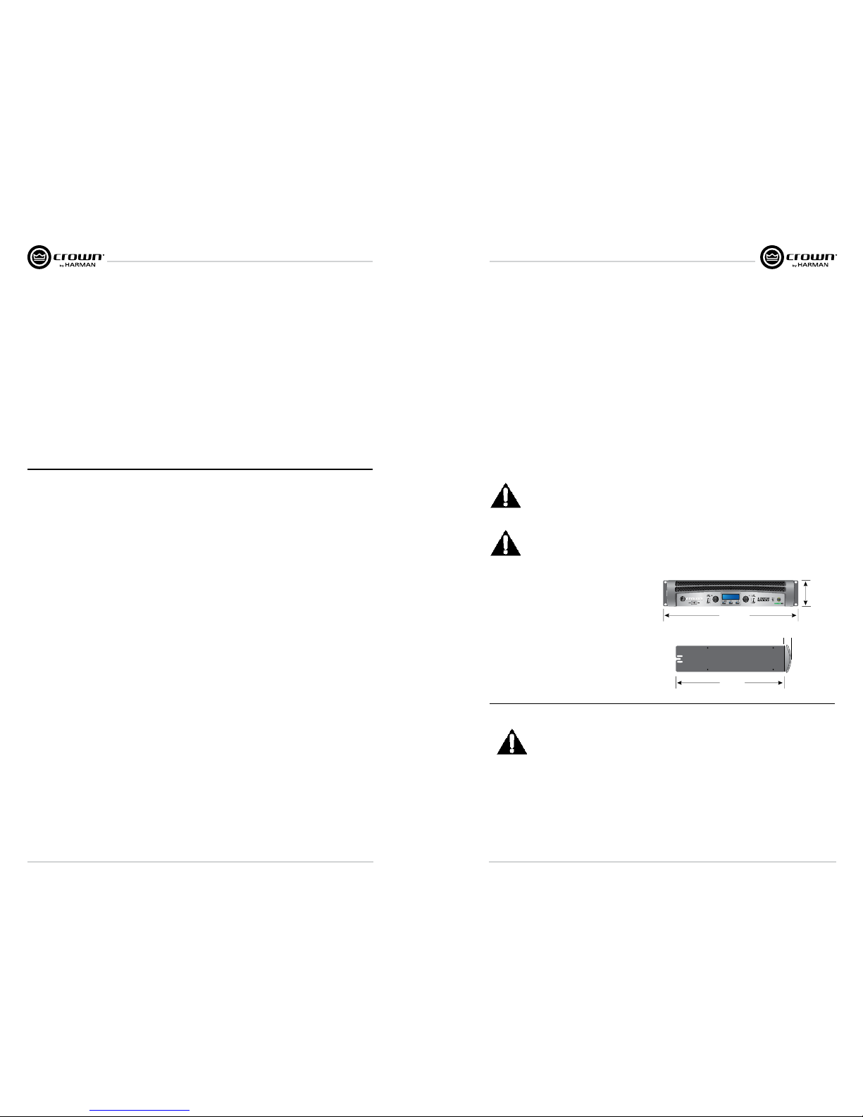
Use a standard 19-inch (48.3 cm) equipment rack
(EIA RS-310B).
You may also stack amps without using a
cabinet.
NOTE: When transporting, amplifiers should be
supported at both front and back.
Setup
1.5 In.
3.8 cm
3.5 In.
8.9 cm
16.2 In.
41.1 cm
48.3 cm
19 In.
Magnetic Field
CAUTION! Do not locate sensitive high-gain equipment such as preamplifiers or tape decks directly
above or below the unit. Because this amplifier has a high power density, it has a strong magnetic
field which can induce hum into unshielded devices that are located nearby. The field is strongest
on the right side and right bottom of the amplifier (facing the amplifier).
If an equipment rack is used, we recommend locating sensitive equipment at least 20 cm
(8 inches) away from the amplifier.
When using an equipment rack, mount units directly on top of each other. Close any open spaces in rack with
blank panels. DO NOT block front or rear air vents. The side walls of the rack should be a minimum of two inches
(5.1 cm) away from the amplifier sides, and the back of the rack should be a minimum of four inches (10.2 cm)
from the amplifier back panel.
Page 4
I-Tech HD Series Power Amplifiers I-Tech HD Series Power Amplifiers
page 6
page 7
Operation ManualOperation Manual
Wire Inputs and Outputs
Wiring basics
• Always use shielded wire for input wiring. The higher the density of the shield (the
outer conductor) the better. Spiral wrapped shield is not recom mended.
• When using unbalanced lines keep the cables as short as possible.
Avoid lengths greater than 10 feet (3 meters).
• Do not run the audio input cables together with the high-level wiring such as loudspeaker wires or
AC cords. (This lessens the chance of hum and noise being induced into the input cables.)
• Turn the entire sound system off before changing any connections. Crown is not liable
for damage incurred when any transducer or compo nent is over driven.
THE CHANNEL 2 INPUT IS IGNORED by default in Bridge Mono mode. It can be summed using the
input source selector and used instead of Channel 1.
For additional information on audio input wiring please refer to the Crown Amplifier Application Guide available
online at www.crownaudio.com. It contains helpful information on
preventing unwanted subsonic frequen cies, radio frequency interference,
ground loops, and feedback oscillation.
When using network connections, pass the CAT 5 cable five times
through a ferrite core, available from Crown Audio Inc. This is to ensure
compliance with emission regulations.
Connecting to AC Mains
WARNING: The third (ground) prong of the supplied AC power cord connector is a
required safety feature. Do not attempt to disable this ground connection by using an
adapter or other methods.
Amplifiers don’t create energy. The AC mains voltage and current must be sufficient to deliver the power you
expect. You must operate your amplifier from an AC mains power source with not more than a 10% variation
above or a 15% variation below the amplifier’s specified line voltage range and within the specified frequency
requirements (indicated on the amplifier’s back panel label). If you are unsure of the output voltage of your AC
mains, please consult your electrician.
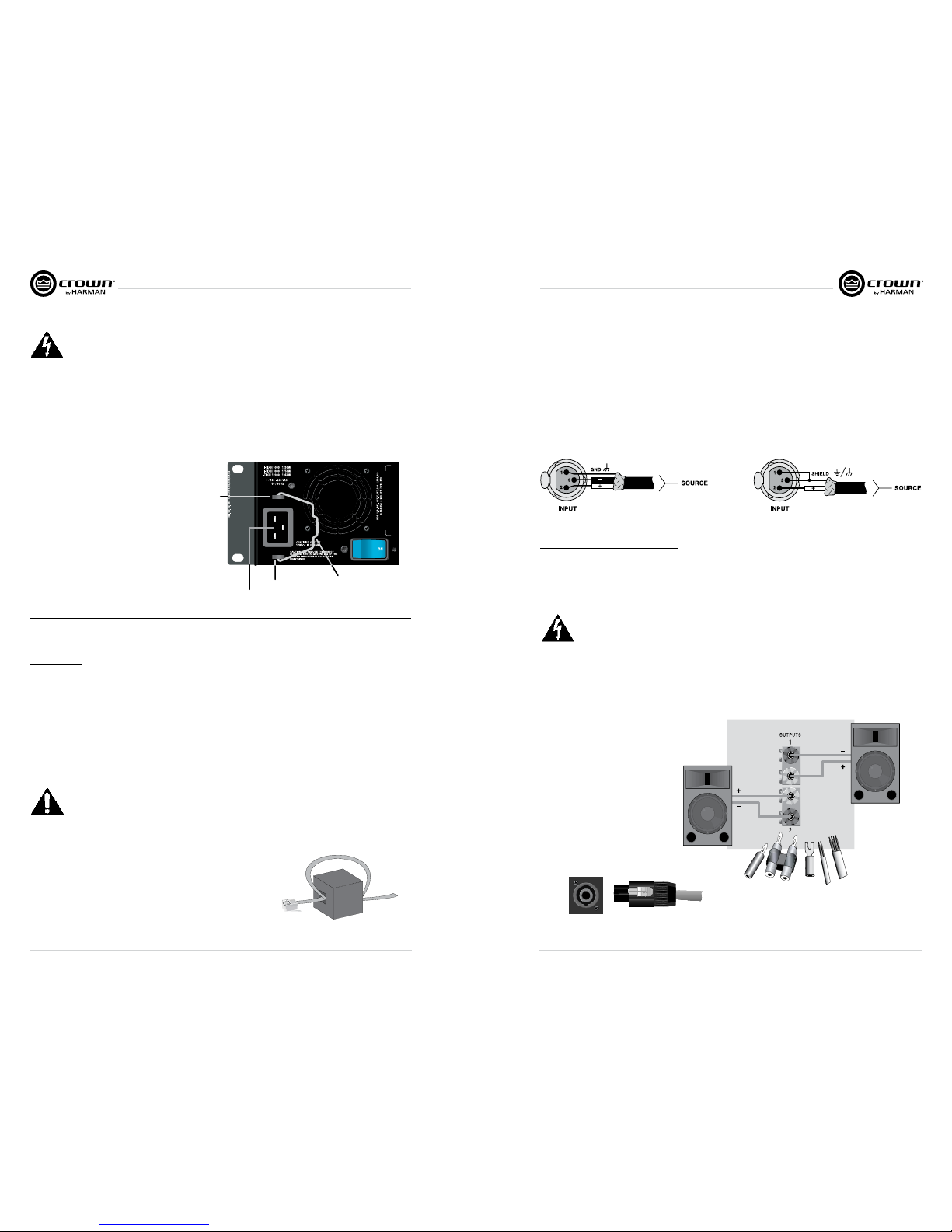
Packed with your I-Tech amplifier is a clip that retains the power cord so it can’t pull out accidentally.
1. Locate the clip in a bag in the I-Tech packing carton.
2. Locate the IEC power connector on the back
of the amplifier. Above and below that
connector are two slots. Stretch the ends of
the clip and insert them into the slots.
3. Plug the power cord all the way into the
amplifier IEC power connector.
4. Pull the clip to the left and snap it onto the
power cord.
IEC Power Connector
Slot
Slot
Clip
Choose Input Wire and Connectors
Crown recommends using pre-built or professionally wired, bal anced line (two-conductor plus shield), 22-24
gauge cables and connectors. Use 3-pin male XLR connectors.
Unbalanced line may also be used but may result in noise over long cable runs.
The image below on the left shows connector pin assignments for balanced analog wiring or AES/EBU digital
wiring. The use of standard analog cable with AES/EBU will result in diminished performance. For best results,
110 ohm shielded twisted-pair cable for AES/EBU signals is highly recommended. The image below on the right
shows connector pin assignments for unbalanced analog wiring.
NOTE: Custom wiring should only be performed by qualified per sonnel.
Choose Output Wire and Connectors
Crown recommends using pre-built or professionally wired, high-quality, two- or four-conductor, heavy gauge
speaker wire and connectors. Use Class 2 output wiring. You may use a 4-pole Speakon
®
connector or banana
plugs, spade lugs, or bare wire for your output connectors. To prevent the possibility of short circuits, wrap or
otherwise insulate exposed loudspeaker cable connectors.
CAUTION – SHOCK HAZARD: Potentially lethal voltages exist at the output connectors
when the amplifier is turned on and is passing a signal.
Using the guidelines below, select the appropriate size of wire based on the distance from amplifier to speaker.
Distance Wire Size
up to 25 ft. 16 AWG
26-40 ft. 14 AWG
41-60 ft. 12 AWG
61-100 ft. 10 AWG
101-150 ft. 8 AWG
151-250 ft. 6 AWG
CAUTION: Never use shielded
cable for output wiring.
Page 5
I-Tech HD Series Power Amplifiers I-Tech HD Series Power Amplifiers
page 8
page 9
Operation ManualOperation Manual
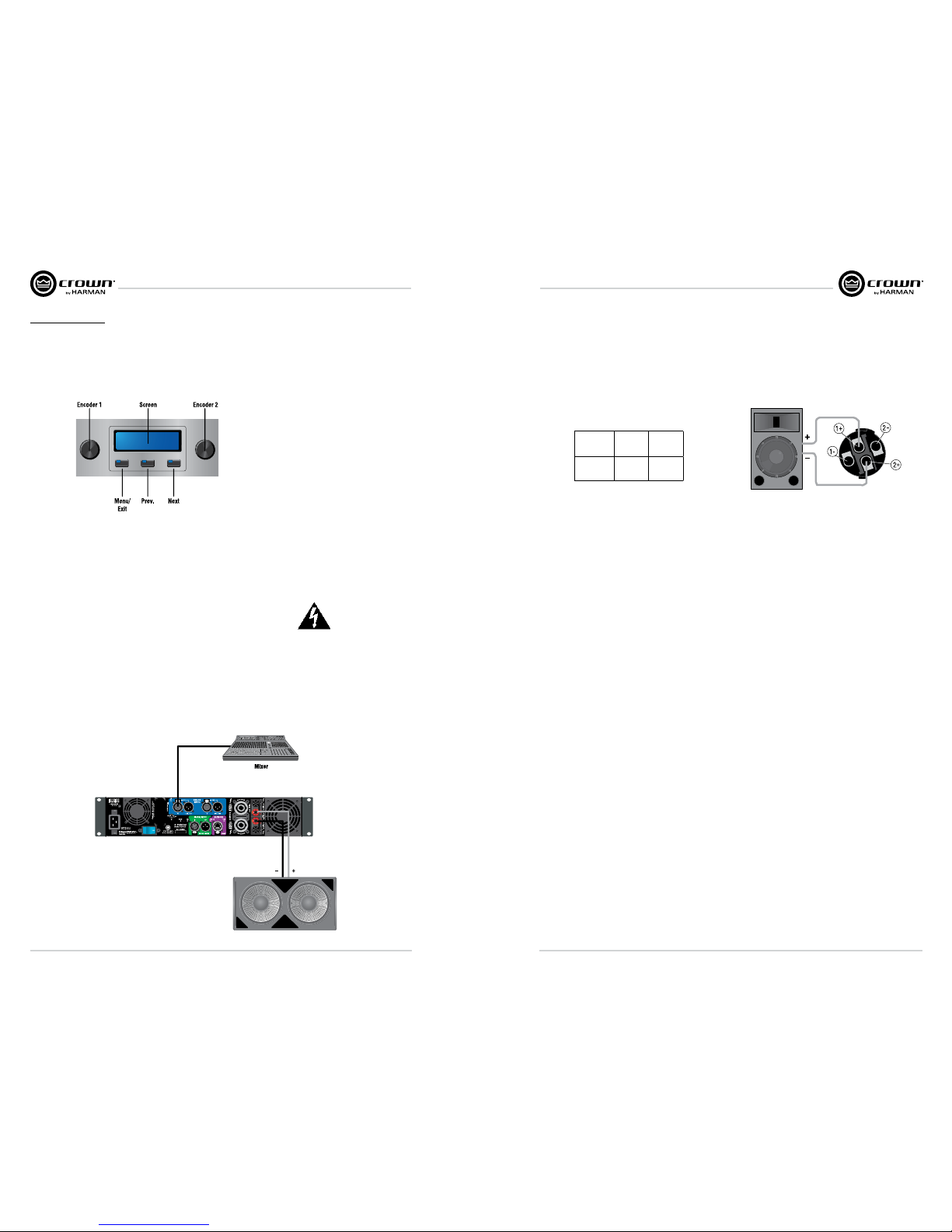
Stereo Mode Wiring
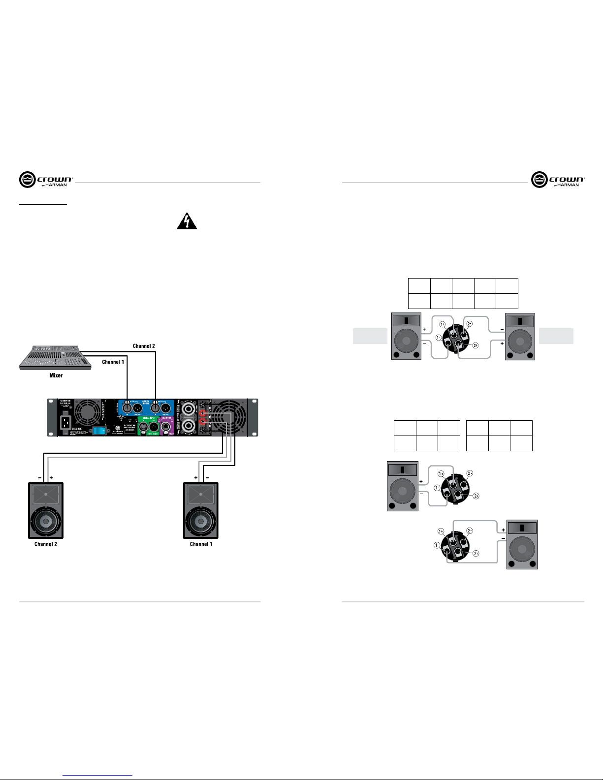
Typical input and output wiring is shown in image below.
IMPORTANT: Turn off the amplifier and unplug its power cord.
INPUTS: Choose one of these options:
• Connect analog input wiring for both channels.
• Connect an AES/EBU digital signal to the AES/EBU connector.
OUTPUTS: Maintain proper polarity (+/–) on output connectors. Use Class 2 output wiring.
The image below shows how to wire stereo speakers to the binding posts. Con nect Channel 1 loudspeaker’s
positive (+) lead to Channel 1 positive (red) terminal of amp; repeat for negative (–). Repeat Channel 2 wiring as
for Channel 1.
To wire stereo speakers to the Speakon® connectors, use one of these methods:
Method 1: Wire one Speakon® cable connector to two speakers. Insert the Speakon® cable connector into the
amplifier’s top Speakon® connector.
Method 2: Plug the Channel 1 speaker into the Channel 1 (top) Speakon® connector, and plug the Channel 2
speaker into the Channel 2 (bottom) Speakon® connector.
PIN 1+ 1– 2+ 2–
CH 1+ 1– 2+ 2–
Stereo Wiring Method 1: Use Top Speakon® Only
Method 1
Method 2
Channel 1
Loudspeaker
Channel 2
Loudspeaker
Channel 1
Loudspeaker
Channel 2
Loudspeaker
Top Speakon
(Channel 1)
Bottom
Speakon
(Channel 2)
Stereo Wiring Method 2: Use Both Speakon®s
PIN 1+ 1–
CH 2+ 2–
PIN 1+ 1–
CH 1+ 1–
Top Speakon
Bottom Speakon
Page 6
I-Tech HD Series Power Amplifiers I-Tech HD Series Power Amplifiers
page 10
page 11
Operation ManualOperation Manual
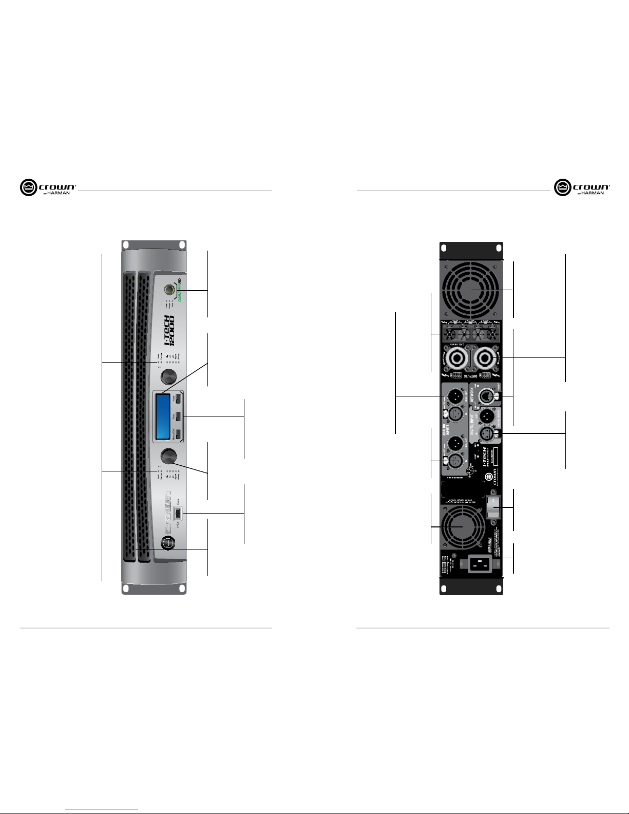
Bridge-Mono Mode
Overview: Turn on the amp, enable Bridge-Mono mode using the LCD Control Screen, turn off the amp, wire it,
and turn it back on.
1. Be sure that no cables are connected to the amplifier. Turn on the front-panel power switch. The LCD
Control Screen will light up.
2. Under the LCD Control Screen, press the Menu/Exit button. Press the Next button until you see OUTPUT
MODE on the screen. If N/A is displayed, OUTPUT MODE is locked via software. If LOCKOUT is displayed,
all the LCD screens are locked via software.
Press an Encoder knob to select BRIDGE MONO. Press the knob again to confirm your choice. Press
Menu/Exit. Turn down both level controls (Encoders) until you reach maximum attenuation.
3. IMPORTANT: Turn off the amplifier and unplug its power cord.
INPUTS: There are three ways to connect an input signal to the amplifier:
• Connect an analog signal source to the Channel-1 amplifier input.
• Connect an AES/EBU digital signal source to the Digital Input IN connector.
NOTE: Crown provides a reference of wiring pin assignments for commonly used connector types in the Crown
Amplifier Application Guide available at
www.crownaudio.com.
OUTPUTS: Use Class 2 output wiring. There are two ways to wire the amplifier output connectors for BridgeMono mode:
NOTE: In Bridge-Mono mode, the
Channel 1 Level control sets the
level; the Channel-2 Level control is
defeated. All Channel-2 objects and
controls are hidden and disabled.
Menu/Exit Prev Next
1. Wire the speaker across the red binding post of each channel. Do not use the black binding posts when
operating in Bridge-Mono mode.
2. Wire the speaker only to the top Speakon® connector as shown in the table below.
PIN 1+ 2+
SPKR
+ –
Top Speakon® Wiring for Bridge-Mono
Page 7

I-Tech HD Series Power Amplifiers I-Tech HD Series Power Amplifiers
page 12
page 13
Operation ManualOperation Manual
Protecting Your Speakers
It’s wise to avoid clipping the amplifier signal. Not only does clipping sound bad, it can damage high-frequency
drivers. To prevent clipping, use System Architect software’s Level Max suite to enable or display the peak voltage
limiter and average power limiter in your amplifier’s built-in DSP. That way, no matter how strong a signal your
mixer produces, the amplifier output will not clip. Set the limiter threshold so that mixer signals above 0 dB or 0
VU on the mixer meters do not quite drive the amplifier into clipping.
Also, avoid sending strong subsonic signals to the amplifier. High-level, low-frequency signals from breath pops
or dropped micro phones can blow out drivers. To prevent subsonic signals, use one of these methods:
• Insert a highpass filter between mixer output and amplifier input (or between mixer and limiter).
• Use the I-Tech’s onboard DSP to set up a highpass filters.
• Switch in highpass filters at your mixer. Set the filter to as high a fre quency as possible that does not affect
your program. For example, try 35 Hz for music and 75 Hz for speech. On each mixer input channel, set the
filter frequency just below the lowest fundamental frequency of that channel’s instrument.
Operation
Startup Procedure
When first turning on your amplifier, follow the procedures in the Quick-Start Guide on page 4 (stereo) or page 5
(bridge-mono).
If you ever need to make any wiring or installation changes, don’t for get to disconnect the power
cord.
For help with determining your system’s optimum gain structure (sig nal levels) please refer to the
Crown Amplifier Application Guide, available online at www.crownaudio.com.
Precautions
Your amplifier is protected from internal and external faults, but you should still take the following
precautions for optimum performance and safety:
1. Before use, your amplifier first must be configured for proper operation, including input and output wiring
hookup. Improper wiring can result in serious operating difficulties. For information on wiring and
configuration, please consult the Setup section of this manual or, for advanced setup techniques, consult
Crown’s Amplifier Application Guide available online at
www.crownaudio.com.
2. Use care when making connections, selecting signal sources and controlling the output level. The load you
save may be your own!
3. Do not short the ground lead of an output cable to the input signal ground. This may form a ground loop and
cause oscillations.
4. WARNING: Never connect the output to a power supply, battery or power main.
Electrical shock may result.
5. Tampering with the circuitry, or making unauthorized circuit changes may be hazardous and
invalidates all agency listings.
6. Do not operate the amplifier with the red Clip LEDs constantly flashing.
7. Do not overdrive the mixer, which will cause clipped signal to be sent to the amplifier. Such signals will be
reproduced with extreme accuracy, and loudspeaker damage may result.
8. Do not operate the amplifier with less than the rated load imped ance. Due to the amplifier’s output protection,
such a configura tion may result in premature clipping and speaker damage.
9. CAUTION – SHOCK HAZARD: Potentially lethal voltages exist at the output connectors when the
amplifier is turned on and is passing a signal.
Remember: Crown is not liable for damage that results from overdriv ing other system components.
Page 8
I-Tech HD Series Power Amplifiers I-Tech HD Series Power Amplifiers
page 14
page 15
Operation ManualOperation Manual
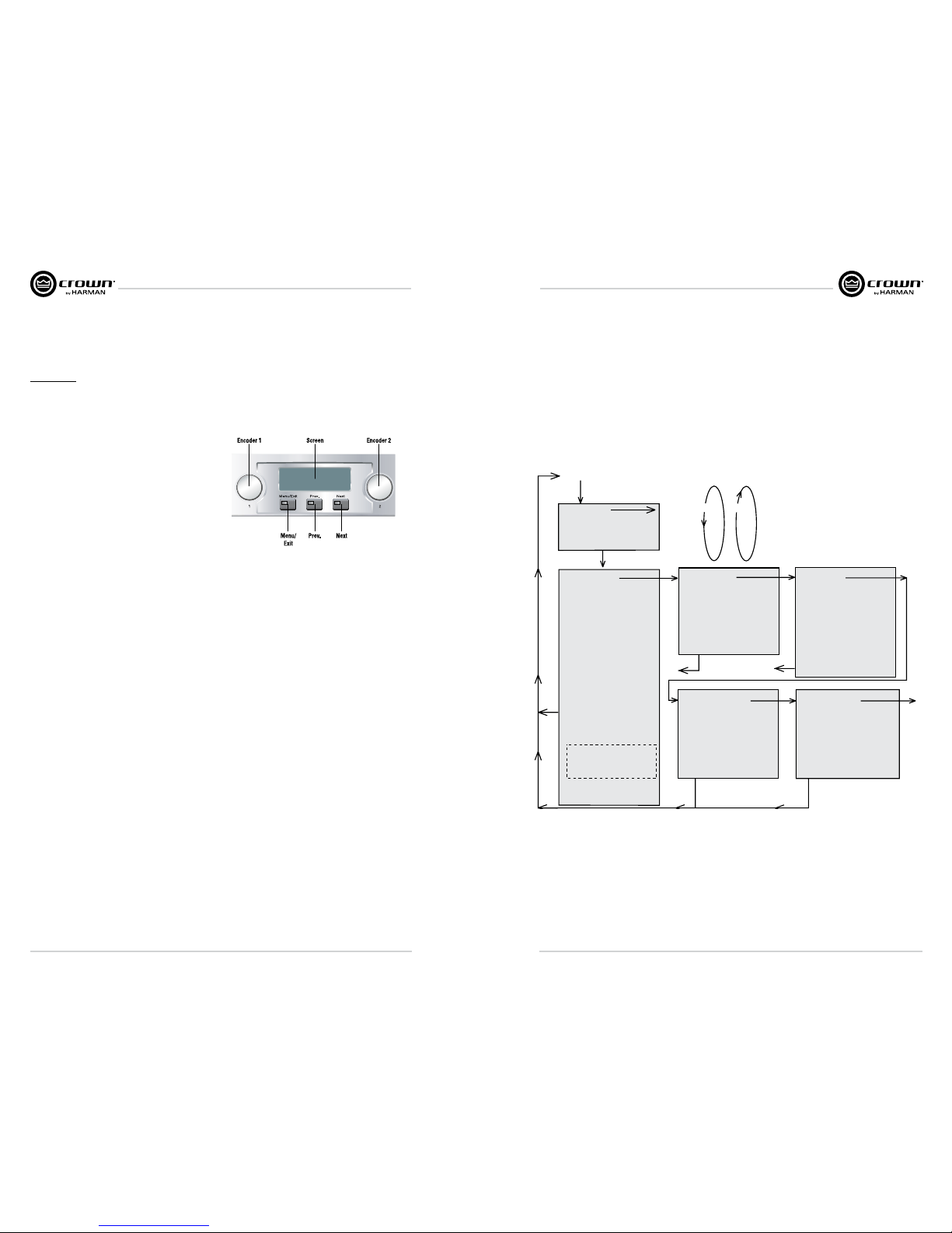
Front Panel Features
Gain (Level) Controls:
Two black rotary level controls,
one for each channel.
Cooling Vents:
Front-to-rear forced airflow
through foam dust filter.
Sel/Prev/Next Buttons:
Three buttons located
underneath the LCD screen
used to access menu items
and front panel lockout.
USB 2.0 Connector:
Accepts a USB drive to transfer
presets from the drive to the
amplifier DSP, and vice versa.
Power Button & Indicator:
Push-on/push-off switch glows
green when AC power is present at
the power cord and the amplifier
circuit breaker is in the “on”
position.
LCD Screen:
Backlit liquid crystal display
shows enabled presets and
speaker processing.
Indicators:
Fault Indicator: Red LED, one per chan nel, flashes when the amplifier outpu t channel has stopped operating. Usu ally this means that the amplifier must be s erviced.
Thermal Indicator: Red LED, one per channel, illuminates when t he channel has shut down due to thermal str ess or overload.
Clip Indicato r: Red LED, one per channel, illuminates when t the channel’s output signal reaches the ons et of audible clipping. The Clip indicator also will ill uminate
during Thermal Level C ontrol (TLC) limiting . The Clip Indicator can be turned of dur ing Blackout mode.
-10 dB Indicator: amplifier o utput is 10 dB below clipping.
-20 dB Indicato r: amplifier output is 20 dB below clipping .
Signal Indicator: selected input signa l is abouve -40 dBu.
Ready Indicator: Green LED, one per channel, illuminates wh en the channel is initialized and ready to produ ce audio output. Indicator is of f when the channel is set
to standby mode via S ystem Architect or in Blackout mo de.
Back Panel Features
Binding Post Output Jacks:
One pair per channel of high-current,
60A color-coded binding posts. Accepts
banana plugs,wire of spade lugs.
Fans:
Provide front to back
forced airflow for cooling.
AC Power
Connector
4-Pole Speakon
®
Output Connectors:
These two connectors accept 2-pole or 4-pole Speakon
connectors. The channel 1 connector is wired for both channels
so it can be used for bridge-mode wiring or stereo wiring of two
speakers to a single Speakon.
Network Connector:
This EtherCon
®
Ethernet
connector is for networking.
Warning: Only connect to
networks that remain inside
the building.
Reset Switch/
Circuit Breaker
Balanced Analog
XLR Inputs:
Provide front to back
forced airflow for cooling.
Balanced Analog XLR Loop-Through Outputs:
Two 3-pin male XLR output connectors are provided (one per
channel). The signal at these connectors is paralleled with the
Input signal for feeding the input signal to other amplifiers.
AES/EBU Digital Input:
This 3-pin female XLR
connector accepts a digital
signal in the AES/EBU format.
Fans:
Provide front to back forced
airflow for cooling.
Page 9
I-Tech HD Series Power Amplifiers I-Tech HD Series Power Amplifiers
page 16
page 17
Operation ManualOperation Manual
Advanced Operation
Navigating the LCD Control Screen
Introduction
The LCD Control Screen and its controls let you configure the ampli fier and access many features that before
were available only through a remote computer. Also, you can recall DSP presets via the front panel. (Some DSP
parameters cannot be adjusted with the LCD Control Screen. That is done in System Architect.)
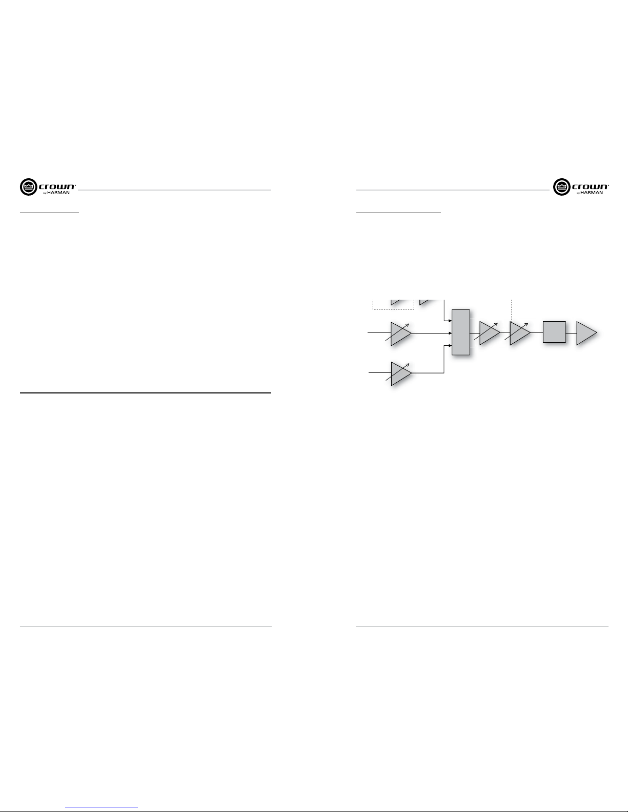
This image shows the parts of the LCD Control Screen. Its
functions are described below. NOTE: Listed functions can
also be controlled in System Architect.
Here’s how to access the various menus and settings in the LCD control screen:
Starting from the Attenuation screen, press Menu/Exit to go to the Sample Rate screen.
• Press Next to go to the next item in the menu.
• Press Prev to go to the previous item in the menu.
• Turn or press either Encoder knob to change the value of the dis played parameter.
• When you see a menu screen, push the knob once to see the items in that menu. Or press Next to go to the
next menu.
• Press Menu/Exit to leave the menu and return to the Attenuation screen at any time.
MENU TREE
Attenuation - Mute - Lockout
Menu button
Sample Rate
Analog Input Sensitivity
Presets
Amp Mode
Locate
ADVANCED MENU
(press knob once to access these
items:)
Attenuator Limits
Attenuator Link
Input Sources
Analog Source Select
Maximum Analog Input
Digital Source Select
AES Source Select
AES Input Trim
AES Input Status
Cobranet Source Select
Cobranet Input Trim
Bandpass Gain
Output Polarity
Input Delay
Speaker Delay
LED Meter Display Type
Bar Meter Display Type
LevelMax
Peak Voltage Limiter
RMS Voltage Limiter
Transducer Thermal Limiter
Pink Noise Generator
SLM (Sweep Load Monitoring)
Front Panel Blackout
Next
Prev
Exit
MONITOR MENU
(press knob once to access
these items:)
Load Monitoring
Thermal %
Thermal Temp deg. C
AC Line Voltage
Operating Time
Watts Output
ALERT MENU
(press knob once to access
these items:)
Amp Output Clip Errors
Analog Input Clip Errors
Thermal Errors
Low Limit Load Errors
High Limit Load Errors
SLM Errors
Line Voltage Errors
Fan Errors
Clear All Error Logs
NETWORKING MENU
(press knob once to access
these items:)
Network Info
Manufacturing Info
HiQnet Node Address
DHCP
IP Address
Subnet Mask
COBRANET MENU
(press knob once to access
these items:)
Cobranet Information
Ch1 Cobranet Rx
Ch2 Cobranet Rx
Cobranet Tx
Cobranet Conductor Priority
Cobranet Transport Latency
Next
Next
Next
Next
Next
ALL MENUS: Next/Previous loops
Exit
Exit
Exit
Exit
Next
To
Sample
Rate
Prev to
Cobranet
Menu
Level
Max
Suite
Some menu items require confirmation: after you request a change, the display might say “Press and hold.” To
confirm a change, press and hold an Encoder knob. If you don’t want the change to occur during a confirmation,
turn the knob or wait five seconds.
The entire front panel or just selected screens can be locked out or set to read only status using System Architect
software. Locked-out screens will either say “Lockout” or the individual parameter will say “N/A”. If a change is
attempted the screen will say “Changes Disabled”.
Sweep Load Monitoring is not available in early I-Tech HD models.
Page 10

I-Tech HD Series Power Amplifiers I-Tech HD Series Power Amplifiers
page 18
page 19
Operation ManualOperation Manual
Presets
Introduction
Your I-Tech HD amplifier has a wide variety of onboard Digital Signal Process ing (DSP). Some applications
for this DSP are speaker configuration (set ting the drive levels, frequency bands, delays and limiting for your
particular speakers), EQ, filtering, compression, and much more. Those functions are described in Section 4.6.
System Architect software lets you adjust the DSP settings, such as filter slope, compression ratio, EQ frequency
bands, and so on.
A preset is a group of DSP settings that configure the amp for a specific application. For example, you might use
one preset that optimizes the amp’s DSP for a JBL Vertec Line Array. You might use another preset that sets up
the DSP for a stereo pair of loudspeakers of your choice. You can choose any of 50 presets with the LCD Control
Screen.
Preset 1 is the factory default preset and cannot be overwritten. It sets up the amplifier for stereo operation with
no DSP.
The I-Tech HD amplifier works with two types of presets:
1. User presets. Using System Architect, you can create your own custom DSP presets, label
them, and send them to the I-Tech HD ampli fier. The amp stores those presets in firmware. You can recall
those presets from the LCD Control Screen.
2. Downloadable presets. Crown and JBL engineers have designed presets that are optimized for various
JBL loudspeakers, such as Vertec Line Arrays. You can download presets from the I-Tech pages in the
Crown website www.crownaudio.com. Then in the software, or with a USB drive, send the preset files to the
I-Tech HD amplifier, where you can recall them from the LCD Control Screen.
We will describe each type of preset in detail.
User Presets
User presets are DSP presets that you set up. This is the basic procedure:
1. Adjust the DSP settings as desired in the System Architect soft ware (not with the LCD Control Screen).
2. Save this group of settings as preset. Give it a label.
3. Download the preset to the I-Tech HD amplifier. See the software Help file for details. As soon as you save
the setting as a preset, it is sent to the amplifier. Another option, described on the next page, is to transfer
the preset file using a USB drive.
4. Select that preset from the LCD Control Screen. The preset will automat ically set the DSP
parameters as you set them up in the control software.
Setting some parameters of the DSP in the I-Tech HD amplifier is done using the control software, not by the
amplifier’s LCD Control Screen. For example, if you want to set filter Q, compression ratio, or graphic EQ, you
would do so within the System Architect software.
5. When you want to recall the preset, select it from the Preset screen in the LCD display. The preset will
automat ically set the DSP parameters as you set them up in the control software.
Downloadable Presets
Crown and JBL engineers have designed I-Tech HD DSP presets that are opti mized for various JBL loudspeakers,
such as Vertec Line Arrays. To use them, follow this procedure in System Architect:
1. Go to the I-Tech pages at www.crownaudio.com.
2. Select Downloads.
3. Click on the file of your choice. It will download to your computer.
4. In System Architect, see the Help file on Presets for details on downloading the pre set to an I-Tech HD
amplifier.Basically, you will open and engage a data frame. The file will overwrite the preset you designate.
Another option, described on the next page, is to transfer the preset file using a USB drive.
5. Recall the preset from the LCD Control Screen. Then your amp will be configured to work with the specified
loudspeaker model.
Digital Audio Options (AES/EBU)
Digital audio inputs allow you to keep the amplifier input signals in the digital domain. Keeping the input signal
digital reduces the number of Dig ital-to-Analog and Analog-to-Digital conversions. This provides better sound
quality and reduces pickup of electrical interference.
The AES/EBU connector provides the most widely accepted format. Con nect an AES/EBU signal to the AES/EBU
connector on the rear panel. If the amplifier’s low-voltage power supply is lost for any reason, the AES input signal
goes directly to the AES output. The amplifier has a digital buffer converter so it will adapt to any AES sample rate
between 32 and 96kHz that is sent to it.
Networking the Amplifier
If you need help understanding network concepts, please see Appendix A on Network and CobraNet Basics.
Please check the System Architect help file for directions on how to use its networking configuration tools.
An I-Tech HD amplifier may be used in an existing I-Tech network and can use existing I-Tech device or venue
files.
You can make the following settings via the front panel or by using the Network Troubleshooter:
HiQnet node address
DHCP off/on
IP address
Subnet mask
Page 11
I-Tech HD Series Power Amplifiers I-Tech HD Series Power Amplifiers
page 20
page 21
Operation ManualOperation Manual
Network Troubleshooter
The network troubleshooter can assist you in setting up your HiQnet network for the first time. Using the
troubleshooter, you can address your components and be informed of addressing and other errors in the system.
Please note that this wizard is designed to work with devices that are on the same physical network segment as
the computer it is running on. It will not work through a router.
Select Network Card
The first page of the wizard lists all the network adapters currently in the computer. If you have more than one
adapter, you can scroll through the list and see the IP Address assigned to each card.
If you have a card with an IP address of 0.0.0.0, it typically means one of several things:
1. The card is disabled.
2. The card is not connected to a network.
3. The card is setup to obtain its address from a DHCP server, and no DHCP server is available.
Select the card that is connected to the HiQnet system and click the Next button. The Wizard will walk you
through the rest of the process. Please see the System Architect online help for more information.
Software-Controllable Onboard DSP
Crown’s latest-generation Digital Signal Processing is built into the I-Tech HD amplifier. Its 24-bit/96kHz
converters offer extremely low noise and extended dynamic range. When you use an I-Tech HD amp, the
loud speaker processors, crossovers, limiters and delays are in the onboard DSP – so you don’t need those rackmounted devices. This drastically cuts setup time, commissioning, rack space and costs.
The I-Tech HD’s DSP can be monitored and controlled with a computer running System Architect software, and
connected to the amplifier Network Connector by a network Category 5 cable.
Some applications for this DSP are:
• Set up signal flow
• Optimize system gain structure
• Set up speaker configurations (set the drive levels, frequency bands, delays and limiting for
your particular speakers)
• Set up EQ, filtering, compression, and much more.
Maximum analog
input
Low +21 dBu (0 dB)
High +15 dBu (+6 dB)
Analog
input
AES
input
Cobranet
input
Analog
input
sensitivity
Source
select
AES input trim
Cobranet input trim
Output
attenuator
Fixed
gain
compensation
Limiters
Amplifier
Low +21 26/32 dB
Hi +15 32/38 dB
Fixed gain
Fixed-Gain mode in the I-Tech HD
Fixed-gain mode makes any I-Tech HD model have the same gain, regardless of output power.
To do that, fixed-gain mode sets the Analog Input Sensitivity to 0 dB gain, then adjusts the Fixed Gain
Compensation fader, and the Maximum Analog Input, to achieve 26 or 32 dB of gain (if the Maximum
Analog Input is set Low), or to achieve 32 or 38 dB of gain (if the Maximum Analog Input is set High), no matter
what model the amplifier is.
However, In fixed-gain mode, the input trims (Analog, AES, CobraNet) can still be adjusted.
Page 12
I-Tech HD Series Power Amplifiers I-Tech HD Series Power Amplifiers
page 22
page 23
Operation ManualOperation Manual
Troubleshooting
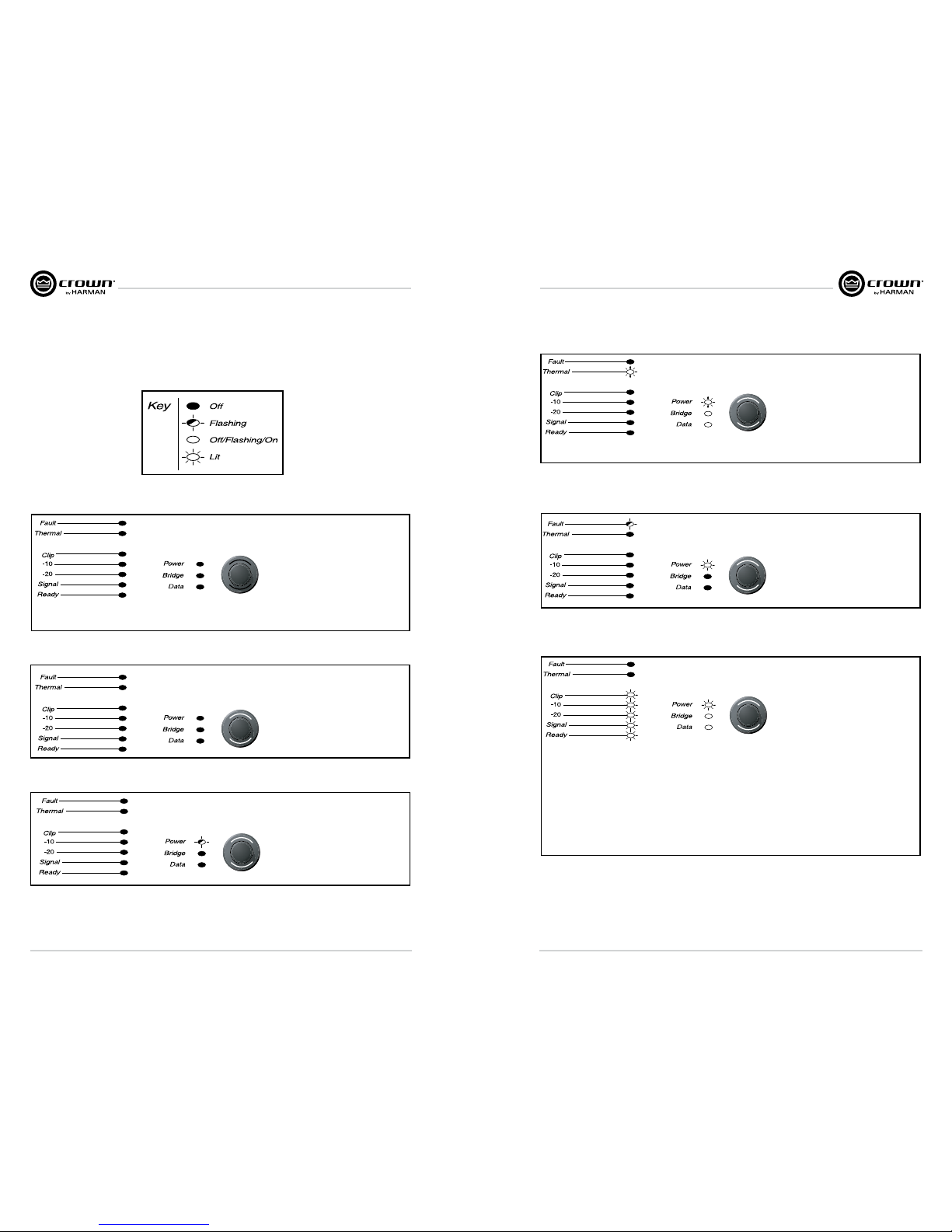
“Off/Flashing/On” means that the LED can be off, or flashing, or on.
CONDITION: Power indicator is
off and power switch is not illuminated.
POSSIBLE REASON:
• The amplier has lost AC power.
• The amplier is not plugged into the
power receptacle.
• Rear-panel breaker is off.
CONDITION: Power indicator
is off and power switch is illuminated.
POSSIBLE REASON:
• The amplier’s power switch is off.
CONDITION: Power indicator is
flashing.
POSSIBLE REASON
• The AC line voltage has dropped below
15% or has risen above 15% of the
rated range.
CONDITION: Thermal indicator is
on.
POSSIBLE REASON:
• The amplier is becoming too hot for safe
operation. Allow amplifier to cool. Check for
loads less than 2 ohms, and for excessive
input levels. Check for proper ventilation.
CONDITION: Fault indicator is
flashing.
POSSIBLE REASON:
• The amplier channel has stopped
operating. Refer the unit to an authorized
Crown Service Center.
CONDITION: Power indicator is
off and power switch is not illuminated.
POSSIBLE REASON:
• Load is wired incorrectly or Output Mode
switch in LCD-screen menu is set incorrectly. Check both.
• Input is overloaded by a signal level that
is too high. Turn down your amplifier level
controls (Encoders), or turn down the
input signal, until the clip light goes out.
Note: If the signal sounds distorted even
though the Clip LED is off, the input signal
may be distorted before it reaches the
amplifier input. Check gain staging and
output levels of the mixer or preamp.
Page 13
I-Tech HD Series Power Amplifiers I-Tech HD Series Power Amplifiers
page 24
page 25
Operation ManualOperation Manual
CONDITION: No sound, even though
the amp has power. Power LED is on with-
out flashing and the amp is receiving an input
sig nal. Signal indicator is on or flashing.
POSSIBLE REASON
• Speakers not connected.
• Open circuit due to speaker failure.
• Ready LED is off. Channel has been set to
standby mode via the software.
• Amplier is in blackout mode. Press or
turn an Encoder to reactivate the LCD
display.
CONDITION: No input signal. Signal
indicator is not flashing even though audio is
applied, and the channel is ready.
POSSIBLE REASON
• Input signal level is very low.
• Another source is selected or routed.
• There is a short on the amplier output. First
disconnect your speakers from the affected
channel(s) one by one to determine if one of
the loads is shorted.
CONDITION: Data indicator not ash
ing, even though host computer
software is active.
POSSIBLE REASON:
• Cable between computer and amplier is bro ken
or not connected.
Note: Data indicator flashes only when the amplifier
is polled for data, or is polled to see whether it is
online.
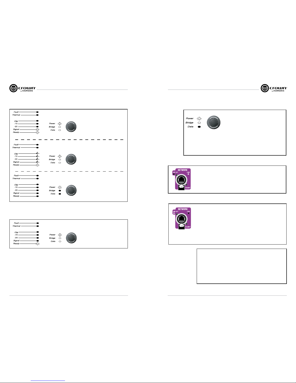
CONDITION: Yellow LINK ACTIVITY indicator in
Ethernet connector does not illuminate or ash.
POSSIBLE REASON:
• Ethernet link is broken.
CONDITION: Computer does not communicate with the
network devices.
POSSIBLE REASON:
• Incorrect wiring. See Section 3.5 letter O on network wiring.
• IP Addressing is not done correctly. Use the Network Troubleshooting
Wizard in System Architect.
CONDITION: COND indicator is off.
POSSIBLE REASON:
• There is only one conductor allowed per network system. This
indicator is lit only when the amplifier is the conductor.
• Amplier is in blackout mode. Press or turn an Encoder to
reactivate the LCD display.
Page 14
I-Tech HD Series Power Amplifiers I-Tech HD Series Power Amplifiers
page 26
page 27
Operation ManualOperation Manual
Specications
Minimum Guaranteed Power I-T5000HD I-T9000HD I-T12000HD
20 Hz - 20 kHz with 0.35% THD
Stereo, 2 ohms (per ch.)
Stereo, 4 ohms (per ch.)
Stereo, 8 ohms (per ch.)
Bridge mono, 4 ohms
Bridge mono, 8 ohms
1800W
2000W
1250W
3600W
4000W
2500W
3000W
1500W
5000W
6000W
3500W
4000W
2100W
7000W
8000W
Performance I-T5000HD I-T9000HD I-T12000HD
Input Sensitivity (volts RMS) for rated output
Adjustable in 0.1V steps from
1.28V to 8V
Adjustable in 0.1V steps from
1.28V to 8V
Adjustable in 0.1V steps from
1.28V to 8V
Voltage Gain for full rated power at 8 ohms
37.1 dB to 22.2 dB 37.9 dB to 23.0 dB 40.1 dB to 24.5 dB
Frequency Response (at 1 watt, 20Hz - 20 kHz) ± 0.25 dB ± 0.25 dB ± 0.25 dB
Signal to Noise Ratio below rated full-bandwidth power, A-weighted > 108 dB > 108 dB > 108 dB
Total Harmonic Distortion (THD) at full rated power at 1 kHz < 0.1% < 0.1% < 0.1%
Intermodulation Distortion (IMD) 60 Hz and 7 kHz at 4:1,
from full rated output to –35 dB
< 0.35% < 0.35% < 0.35%
Maximum Input Level +15 dBu or +21 dBu, depending on
setting of maximum input level
+15 dBu or +21 dBu, depending on
setting of maximum input level
+15 dBu or +21 dBu, depending on
setting of maximum input level
Latency 1.16 mS at 48 kHz, 529 µS at 96 kHz 1.16 mS at 48 kHz, 529 µS at 96 kHz 1.16 mS at 48 kHz, 529 µS at 96 kHz
A/D, D/A Converters 24-bit 96 kHz Cirrus Logic 24-bit 96 kHz Cirrus Logic 24-bit 96 kHz Cirrus Logic
Digital Input AES/EBU, 24-bit, 32-96 kHz.
Onboard sample rate converter.
AES/EBU, 24-bit, 32-96 kHz.
Onboard sample rate converter.
AES/EBU, 24-bit, 32-96 kHz.
Onboard sample rate converter.
Network Onboard HiQnet and TCP/IQ, compatible
with standard 100Mb Ethernet hardware
Onboard HiQnet and TCP/IQ, compatible
with standard 100Mb Ethernet hardware
Onboard HiQnet and TCP/IQ, compatible
with standard 100Mb Ethernet hardware
DSP 24-bit conversion with 32-bit, floating-
point DSP processing
24-bit conversion with 32-bit, floating-
point DSP processing
24-bit conversion with 32-bit, floating-
point DSP processing
Attenuators Speed-sensitive rotary encoders, 0.5 dB
steps, range 0 to –100 dB.
Speed-sensitive rotary encoders, 0.5 dB
steps, range 0 to –100 dB
Speed-sensitive rotary encoders, 0.5 dB
steps, range 0 to –100 dB
Performance I-T5000HD I-T9000HD I-T12000HD
Damping Factor (8 ohms): 20 Hz to 100 Hz > 5000 > 5000 > 5000
Crosstalk (below rated power, 20 Hz to 1 kHz) > 80 dB > 80 dB > 80 dB
Common Mode Rejection (CMR) (20 Hz to 1 kHz) > 55 dB, typically > 70 dB > 55 dB, typically > 70 dB > 55 dB, typically > 70 dB
DC Output Offset (Shorted input) < ± 3 mV < ± 3 mV < ± 3 mV
Input Impedance (nominal) 20 kilohms balanced, 10 kilohms
unbalanced
20 kilohms balanced, 10 kilohms
unbalanced
20 kilohms balanced, 10 kilohms
unbalanced
Load Impedance (Note: Safe with all types of loads)
Stereo
Bridge Mono
1-2-4-8-16 ohms
2-4-8 ohms
1-2-4-8-16 ohms
2-4-8 ohms
1-2-4-8-16 ohms
2-4-8 ohms
Required AC Mains Universal AC input, 100-240VAC (±15%),
50/60 Hz. Max. AC mains voltage
277VAC.
Universal AC input, 100-240VAC (±15%),
50/60 Hz. Max. AC mains voltage
277VAC.
Universal AC input, 100-240VAC (±15%),
50/60 Hz. Max. AC mains voltage
277VAC.
AC Line Connector USA, UK, European, Australia, India USA, UK, European, Australia, India USA, UK, European, Australia, India
Construction I-T5000HD I-T9000HD I-T12000HD
Ventilation Flow-through ventilation from front
to back
Flow-through ventilation from front
to back
Flow-through ventilation from front
to back
Cooling Dual-zone, microprocessor controlled,
continuously variable speed fans
Dual-zone, microprocessor controlled,
continuously variable speed fans
Dual-zone, microprocessor controlled,
continuously variable speed fans
Dimensions EIA Standard 19-inch rack mount width
(EIA RS-310B), 3.5-inch (8.9-cm) height,
16.2-inch (41.1-cm) depth behind front
mounting surface
EIA Standard 19-inch rack mount width
(EIA RS-310B), 3.5-inch (8.9-cm) height,
16.2-inch (41.1-cm) depth behind front
mounting surface
EIA Standard 19-inch rack mount width
(EIA RS-310B), 3.5-inch (8.9-cm) height,
16.2-inch (41.1-cm) depth behind front
mounting surface
Weight
Net
Shipping
28 pounds (12.7 kg)
36 pounds (16.3 kg)
28 pounds (12.7 kg)
36 pounds (16.3 kg)
28 pounds (12.7 kg)
36 pounds (16.3 kg)
Page 15
I-Tech HD Series Power Amplifiers I-Tech HD Series Power Amplifiers
page 28
page 29
Operation ManualOperation Manual
Charts
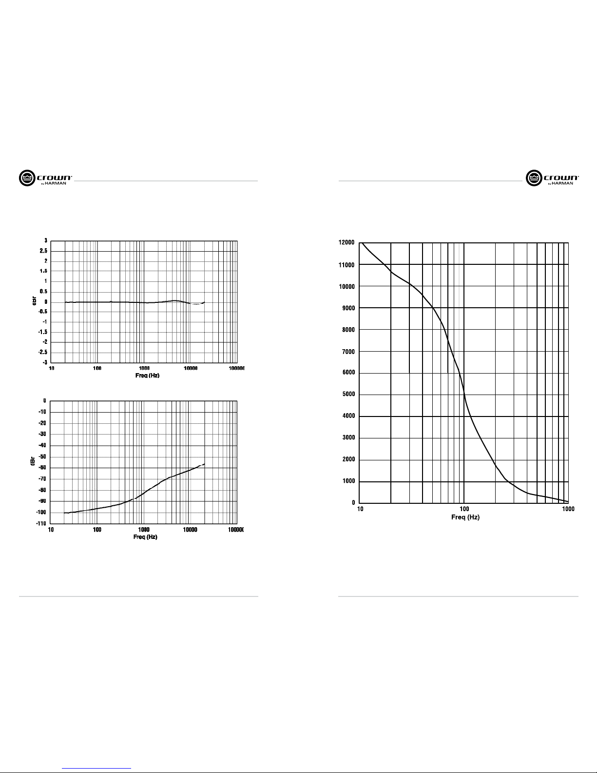
Typical Frequency Response (1W)
Typical Crosstalk vs. Frequency
Typical Damping Factor vs. Frequency
Page 16
I-Tech HD Series Power Amplifiers I-Tech HD Series Power Amplifiers
page 30
page 31
Operation ManualOperation Manual
I-Tech 5000HD AC Current Draw and Thermal Dissipation:
Pink noise 12dB crest factor, bandwidth limited 22Hz to 22kHz.
Typical line impedance used.
Data based on both channels driven.
Line Current
120VAC
Watts Out
Per 1A
Amp Line
Current
Line Current
208VAC
Watts Out
Per 1A
Amp Line
Current
Line Current
230VAC
Watts Out
Per 1A
Amp Line
Current
Btu/hr kcal/hr
Idle (sleep mode) 0.8 0.95 0.9 53 182 157
Idle (awake) 1.6 1.4 1.3 172 587 505
1/8th Power Pink Noise 8 Ohms/Ch.
Typical of program material 16 Ohms Bridge
just at clip. 4 Ohms/Ch.
8 Ohms Bridge
2 Ohms/Ch.
4 Ohms Bridge
1/3rd Power Pink Noise 8 Ohms/Ch.
Typical of program material 16 Ohms Bridge
with severe clipping. 4 Ohms/Ch.
8 Ohms Bridge
2 Ohms/Ch.
4 Ohms Bridge
Load
Thermal Dissipation
305
1413 356
5.3 94.659.6
64.9 116.3
2426 612
4108.0 476
17.8 711
17.7 115.3 128.7 824
142.1
709
4.8
6.6
10.5
10.7
1491
2814
437
3.4
4.7 414
3.1
4.4
I-T5000HD
10.9
1625
376
1040 262
7.8
4.4
6.0
9.5
9.4
58.1
77.1
77.0
70.3
106.9
96.1
126.2
129.1
106.0
139.9
Watts
Dissipated
120VAC 208VAC 230VAC
102.6
AC Power Draw and thermal Dissipation
I-Tech 9000HD AC Current Draw and Thermal Dissipation:
Pink noise 12dB crest factor, bandwidth limited 22Hz to 22kHz.
Typical line impedance used.
Data based on both channels driven.
Line Current
120VAC
Watts Out
Per 1A
Amp Line
Current
Line Current
208VAC
Watts Out
Per 1A
Amp Line
Current
Line Current
230VAC
Watts Out
Per 1A
Amp Line
Current
Btu/hr kcal/hr
Idle (sleep mode) 1.0 1.0 0.95 60 205 177
Idle (awake) 2.1 1.7 1.6 225 767 660
1/8th Power Pink Noise 8 Ohms/Ch.
Typical of program material 16 Ohms Bridge
just at clip. 4 Ohms/Ch.
8 Ohms Bridge
2 Ohms/Ch.
4 Ohms Bridge
1/3rd Power Pink Noise 8 Ohms/Ch.
Typical of program material 16 Ohms Bridge
with severe clipping. 4 Ohms/Ch.
8 Ohms Bridge
2 Ohms/Ch.
4 Ohms Bridge
6.6 4.2 3.857.6 91.2 99.8 392 1338 337
593 2024 510
13.6 8.1 7.474.4 125.3 137.2
27.6 16.0 14.373.9 127.2 141.0
11.6 7.0 6.365.7 108.8 120.4
11.5 6.8 6.255.9 96.5 105.3 2373 598
1149 3921 988
579 1977 498
695
14.9 13.667.0 113.5 4173 105225.0 1223124.3
I-T9000HD
Load
120VAC 208VAC 230VAC
Watts
Dissipated
Thermal Dissipation
Page 17
I-Tech HD Series Power Amplifiers I-Tech HD Series Power Amplifiers
page 32
page 33
Operation ManualOperation Manual
I-Tech 12000HD AC Current Draw and Thermal Dissipation:
Pink noise 12dB crest factor, bandwidth limited 22Hz to 22kHz.
Typical line impedance used.
Data based on both channels driven.
Line Current
120VAC
Watts Out
Per 1A
Amp Line
Current
Line Current
208VAC
Watts Out
Per 1A
Amp Line
Current
Line Current
230VAC
Watts Out
Per 1A
Amp Line
Current
Btu/hr kcal/hr
Idle (sleep mode) 0.9 1.1 1.0 62 212 183
Idle (awake) 2.0 1.8 1.6 213 726 625
1/8th Power Pink Noise 8 Ohms/Ch.
Typical of program material 16 Ohms Bridge
just at clip. 4 Ohms/Ch.
8 Ohms Bridge
2 Ohms/Ch.
4 Ohms Bridge
1/3rd Power Pink Noise 8 Ohms/Ch.
Typical of program material 16 Ohms Bridge
with severe clipping. 4 Ohms/Ch.
8 Ohms Bridge
2 Ohms/Ch.
4 Ohms Bridge
441 1504 3798.3 63.6 103.35.1 4.7
14.6 68.8 2394 603
14.2 764 2607 657
8.7
18.1 715 2439 615
144.2
701
1370 4677 1179
1589 5425 1368118.0 131.117.9
8.2
33.9
35.1
11.0
20.8
19.9
9.9
18.7
62.9
77.4
76.3
69.2
128.3
128.6
115.2
106.1
8.0
7.7
111.8
124.5
113.6
230VAC
142.0
Watts
Dissapited
Thermal Dissipation
I-T12000HD
Load
120VAC 208VAC
Protection System
Your Crown amplifier provides extensive pro tection and diagnostic capabilities, including thermal level control,
fault indicators, high-pass filtering, DC protect, AC under/over volt age protection, inrush limiting, and variablespeed fans with tachometer feedback. Microprocessor monitors fans, and signals an error via System Architect if
fans are not operating.
Thermal Level Control (TLC)
If the amplifier becomes too hot for safe opera tion, the TLC will engage the input compressor and the clip LED will
illuminate. By compress ing the input, the amplifier will not generate as much heat and will have a chance to cool
down. The degree of compression is proportional to the amount of overheating. This feature allows the show to go
on, rather than having the amplifier shut down, and only occurs in extreme situations.
Circuit Breaker
If the current draw of the amplifier exceeds safe limits, this breaker automatically disconnects the power supply
from the AC mains.
Advanced Featured
Global Switching Power Supply with PFC
Thanks to its global power supply, the I-Tech amplifier works anywhere in the world. There’s no need to reset an
AC mains voltage switch, and no need to order a special model. The amp will work and meet all specs on 100V 240VAC, 50/60 Hz.
Crown’s Switching Power Supply minimizes the amplifier’s weight.
Typical non-switching power supplies require large, heavy transformers in order to produce the required power at
the output stage. These transformers must be large to operate at 50 to 60 Hz (standard AC supplied by the power
company).
By contrast, switching power supplies can operate with a much smaller (and lighter) trans former because they first
convert the AC up to a much higher frequency, thereby reducing waste.
Power Factor Correction (PFC) controls how your amplifier draws current from the AC mains. Instead of drawing
high-magnitude cur rent spikes that reduce the capacity of your power distro (and couple noise into other sys tem
components), PFC draws a smooth and quiet current waveform that is in phase with the mains voltage waveform.
PFC allows you to reduce the size and weight of your power distri bution and improve the performance of your
signal processors.
Color-Coded Overlay
The labels on the rear panel are color coded to group similar functions under common colors.
Page 18

I-Tech HD Series Power Amplifiers I-Tech HD Series Power Amplifiers
page 34
page 35
Operation ManualOperation Manual
Optimized system gain structure maximizes signal to noise within the sys tem. Adjusting your amplifier to fit
within an optimized system gain struc ture is accomplished by properly setting both the sensitivity and attenuation
controls within the amplifier. I-Tech amplifiers offer 149 sensi tivity and gain settings allowing very fine adjustment
of the amplifier’s gain and voltage sensitivity. The Appendix section of the I-Tech Application guide (online at
www.crownaudio.com) provides charts with sensitivity in volts and gain in dB for each sensitivity/gain setting.
With other amplifiers, it is often necessary to apply attenuation in order to achieve the desired sound pressure
level. Large amounts of attenuation are not necessary with I-Tech amplifiers and can, in fact, degrade
performance. The attenuation adjustment should only be used for small (3 dB) or tempo rary adjustments in
amplifier gain. Instead, set the sensitivity/gain of your I-Tech amplifier so that you can achieve the desired output
with the attenu ators at or near 0 dB.
Example: Suppose that you are using an I-T9000HD with the sensitivity/gain set at 1.4V/37.1 dB. After optimizing
the gain structure of the rest of your system you find that attenuating the amplifier by 10 dB produces the desired
loudness. The same output level, with improved signal-to-noise ratio and headroom, can be achieved by using 0
dB of attenuation and by setting the amplifier sensitivity/gain to 5.81V/27.0 dB (37 dB – 10 dB = 27 dB).
Note: as indicated in the online appendix, the list of possible sensitivity settings is different for each position of
the max input setting. If, while adjusting sensitivity/gain in your amplifier, you do not find the setting you need, try
changing the status of the max input setting and search again.
Setting Sensitivity for Best Gain Staging
Crown amplifiers are quality units that rarely require ser vicing. Before returning your unit for service, please contact Crown Technical Support to verify the need for servicing.
This unit has very sophisticated circuitry which should only be serviced by a fully trained technician. This is one
reason why each unit bears the following label:
CAUTION: To prevent electric shock, do not remove covers. No user serviceable parts inside.
Refer servicing to a qualified technician.
Complete the Crown Audio Factory Service Information form, in the back of this manual, when returning a Crown
product to the factory or authorized service center. The form must be included with your product inside the box
or in a packing slip envelope securely attached to the outside of the shipping carton. Do not send this form
separately.
Warranty is only valid within the country in which the product was purchased.
Service
International and Canada Service
Service may be obtained from an authorized service cen ter. (Contact your local Crown/Amcron representative
or our office for a list of authorized service centers.) To obtain service, simply present the bill of sale as proof of
purchase along with the defective unit to an authorized service center. They will handle the necessary paperwork
and repair.
Remember to transport your unit in the original factory pack.
US Service
Service may be obtained in one of two ways: from an authorized service center or from the factory. You may
choose either. It is important that you have your copy of the bill of sale as your proof of purchase.
Service at a US Service Center
This method usually saves the most time and effort. Sim ply present your bill of sale along with the defective unit
to an authorized service center to obtain service. They will handle the necessary paperwork and repair. Remem ber
to transport the unit in the original factory pack. A list of authorized service centers in your area can be obtained
from Crown Factory Service, or online from
http://www.crownaudio.com/support/servcent.htm.
Factory Service
Crown accepts no responsibility for non-serviceable product that is sent to us for factory repair. It is the owner’s
responsibility to ensure that their product is ser viceable prior to sending it to the factory. Serviceable product list
is available at
http://crownweb.crownintl.com/crownrma/.
For more information, please contact us direct.
A Service Return Authorization (SRA) is required for product being sent to the factory for repair. An SRA can be
completed online at www.crownaudio.com/support/factserv.htm. If you do not have access to the web, please call
Crown’s Customer Service at 574.294.8200 or 800.342.6939 extension 8205.
For warranty service, we will pay for ground shipping both ways in the United States. Contact Crown Customer
Service to obtain prepaid shipping labels prior to send ing the unit.
Page 19

I-Tech HD Series Power Amplifiers I-Tech HD Series Power Amplifiers
page 36
page 37
Operation ManualOperation Manual
Or, if you prefer, you may prepay the cost of shipping, and Crown will reimburse you. Send copies of the shipping
receipts to Crown to receive reimbursement. Your repaired unit will be returned via UPS ground. Please contact us
if other arrangements are required.
Factory Service Shipping Instructions:
1. Service Return Authorization (SRA) is required for product being sent to the factory for service. Please
complete the SRA by going to
www.crownaudio.com/support/factserv.htm. If you do not have access to our website, call 1.800.342.6939,
extension 8205 and we’ll create the SRA for you.
2. See packing instructions that follow.
3. Ship product to:
CROWN AUDIO FACTORY SERVICE
1718 W MISHAWKA RD.
ELKHART, IN 46517
4. Use a bold black marker and write the SRA number on three sides of the box.
5. Record the SRA number for future reference. The SRA number can be used to check the repair status.
Packing Instructions
Important: These instructions must be followed. If they are not followed, Crown Audio, Inc. assumes no responsibility for damaged goods and/or accessories that are sent with your unit.
1. Fill out and include the Crown Audio Factory Ser vice Information sheet in the back of this manual.
2. Do not ship any accessories (manuals, cords, hard ware, etc.) with your unit. These items are not needed to
service your product. We will not be responsibility for these items.
3. When shipping your Crown product, it is important that it has adequate protection. We recommend you use the
original pack material when returning the product for repair. If you do not have the original box, please call
Crown at 800.342.6939 or 574.294.8210 and order new pack material. See instructions for “foam-in-place”
shipping pack. (Do not ship your unit in a wood or metal cabinet.)
4. If you provide your own shipping pack, the mini mum recommended requirements for materials are as follows:
a. 275 P.S.I. burst test, Double-Wall carton that allows for 2-inch solid Styrofoam on all six sides of unit or 3
inches of plastic bubble wrap on all six sides of unit.
b. Securely seal the package with an adequate carton sealing tape.
c. Do not use light boxes or “peanuts”. Damage caused by poor packaging will not be covered under war ranty.
Using your ‘foam-in-place’ shipping pack
Note: The foam-in-place packing is molded so that there is only one correct position for your product.
1. Open carton and lift center cushion leaving both end-cushions in place.
2. Carefully place your product with the product’s front panel facing the same direction as arrows indicate.
3. Reset center cushion down over top of product’s chassis. The foam-in-place packing was molded to
accommodate different chassis depth sizes. If your product’s chassis does not completely fill the foam-in-place
cavity, you may use a soft but solid packing material (such as paper or bubble wrap) behind the chassis.
4. Enclose the completed Crown Audio Factory Service Information form (or securely attach it to the outside of
carton) and re-seal the shipping pack with a sturdy carton sealing tape.
Estimate Approval
Approval of estimate must be given within 30 days after being notified by Crown Audio Inc. Units still in the possession of Crown after 30 days of the estimate will become the property of Crown Audio Inc.
Payment of Non-Warranty Repairs
Payment on out-of-waranty repairs must be received within 30 days of the repair date. Units unclaimed after 30
days become the property of Crown Audio Inc.
If you have any questions, please contact Crown Factory Service.
Crown Factory Service
1718 W. Mishawaka Rd.,
Elkhart, Indiana 46517 U.S.A.
Telephone:
574.294.8200
800.342.6939 (North America,
Puerto Rico, and Virgin Islands only)
Facsimile:
574.294.8301 (Technical Support)
574.294.8124 (Factory Service)
Internet:
http://www.crownaudio.com
Page 20

I-Tech HD Series Power Amplifiers I-Tech HD Series Power Amplifiers
page 38
page 39
Operation ManualOperation Manual
SUMMARY OF WARRANTY
Crown In ternational , 1718 West Mis hawaka Roa d, Elkhart, I ndiana 46517-40 95 U.S.A. w arrants to you , the ORIGINA L
PURCHA SER and ANY S UB SEQU ENT OWNER of e ach NEW Crow n product, for a p eriod of five (5) ye ars from the
date of p urchase by th e original purch aser (the “w arranty pe riod”) that th e new Crown prod uct is fre e of defects in
mater ials and workm anship. We furt her warran t the new Crown pr oduct regar dless of the re ason for failur e, except as
exclude d in this War r anty.
Warranty is only valid with in the country in which the p roduct wa s purchased.
ITEM S EXCLUDED FR OM THIS CROWN WA RRANT Y
This Crow n Warranty i s in effect onl y for failure of a new C rown product w hich occurre d within the War ranty Perio d. It
does no t cover any produ ct which has b een damage d because of a ny inten ti onal misuse, ac cident, negli gence, or los s
which is c overed under a ny of your insura nce contrac ts. This Crown W arranty al so does not ext end to the new Cro wn
produc t if the serial nu mber has bee n defaced, a ltered, or rem oved.
WHAT THE WARR ANTOR WIL L DO
We will rem edy any defe ct, regardle ss of the rea son for failure (exc ept as exclude d), by repair, repl acement, or r efund.
We may not e lect refund u nless you agre e, or unless we ar e unable to pro vide repl acement, a nd repair is not pr actical
or cann ot be timely mad e. If a refund is el ected, then y ou must make th e defective o r malfunctio ning product av ailable
to us fre e and clear of all lie ns or other encu mbrances. T he refund will b e equal to the ac tual purcha se price, not
includin g inter es t, insurance , closing costs , and other fina nce charge s less a reaso nable depre ciation on the pro duct
from the d ate of original p urchase. War r anty work ca n only be perf ormed at our au tho rized s ervice ce nters or at the
facto ry. Warrant y work for some pro ducts can on ly be perform ed at our fact ory. We will remed y the defect a nd ship
the prod uct from the se rvice cen ter or our facto ry within a rea sonable time a fter recei pt of the defec t ive product at o ur
author ized servi ce center or ou r factory. All ex penses in rem edying the de fect, includ ing surface s hipping costs in t he
United S tates, will be b orne by us. (You mu st bear the ex pense of shippi ng the product b etween an y for eign co untry
and the p ort of entry in t he United Sta tes including t he return ship ment, and all ta xes, dutie s, and other cus toms fees
for such f or eign shipm ents.)
HOW TO OB TAIN WARRANTY S ERVIC E
You must not ify us of your nee d for warran ty ser v ice within the w arranty p eriod. All comp onents must b e shipped in a
facto ry pack, whic h, if needed, m ay be obtaine d from us free of c harge. Corre ctive action w ill be taken wit hin a reasonable tim e of the date of re ceipt of the def ective prod uct by us or our aut horized ser vice cente r. If the re pairs made by u s
or our aut horized ser vice cente r are not satisf actory, notif y us or our autho ri zed servic e center imme diately.
DISCL AIMER OF CON SEQUENTI AL AND I NCIDENTAL DA MAGES
YOU ARE N OT ENTITLE D TO RECOVER FR OM US ANY INCIDE NTAL DAMAGE S RESULTING FRO M ANY DEFECT I N
THE NE W CROWN PRODUC T. THIS INC LUDES ANY DAM AGE TO ANOTH ER PRODUCT OR PR ODUCTS RESULT ING
FROM SUC H A DEFECT. SOME STATES D O NOT ALLOW THE E XCLUSION OR LIM ITATIONS OF INCIDE NTAL OR
CONSEQ UENTIAL DA M AGES, S O THE ABOVE L IMITATION OR EXCL U S ION MAY NOT APPLY TO YOU.
WARRANTY ALTERATIONS
No pers on has the aut hority to enlar ge, amend, or m odify this Crow n Warranty. Th is Crown War ranty i s not extende d
by the len gth of time whic h you are depriv ed of the use of th e new Crown prod uct. Repair s and replace ment parts
provide d under the ter ms of this Crown Wa rranty sha ll carry only t he unexpired po rtion of this Crow n Warrant y.
DESIGN CHANGES
We rese rve the right to c hange the de sign of any produ ct from time to tim e without noti ce and with no obli gation to
make co rresponding c hanges in prod ucts previo usly manufac tured.
LEGA L REMEDIES OF P URCHASER
THIS CRO WN WARRAN TY GIVES YOU S PECIFIC LEG AL RIGHTS, YOU M AY ALSO HAVE OTH ER RIGHTS WH ICH
VARY FROM S TATE TO STATE. N o action to enfo rce this Crown Wa rranty sha ll be commenc ed after exp iration of the
warranty period.
THIS STATE MENT OF WARR ANTY SUP ERSEDES AN Y OTHERS CON TAINE D IN THIS MANUA L FOR CROWN
PRODUCTS. 5/11
Warranty — UNITED STATES & CANADA
SUMMARY OF WARRANTY
Crown In ternational , 1718 West Mis hawaka Roa d, Elkhart, I ndiana 46517-40 95 U.S.A. w arrants to you , the ORIGINA L
PURCHA SER and ANY S UB SEQU ENT OWNER of e ach NEW Crow n1 product, for a pe riod of five (5) yea rs from the
date of p ur chase b y the original pur chaser (the “ warrant y period”) th at the new Crown p roduct is fre e of defects in
mater ials and workm anship, and we fu rther warr ant the new Cro wn product re gardless of th e reason for f ailure, except
as exclu ded in this Warra nty.
Warranty is only valid with in the country in which the p roduct is pu rchased.
Note: If y our unit bears t he name “Amcro n,” please subs titute it for th e name “Crown” in t his warrant y.
ITEM S EXCLUDED FR OM THIS CROWN WARR ANTY
This Crow n Warranty i s in effect onl y for failure of a new C rown product w hich occurre d within the War ranty Perio d. It
does no t cover any produ ct which has b een damage d because of a ny inten ti onal misuse, ac cident, negli gence, or los s
which is c overed under a ny of your insura nce contrac ts. This Crown W arranty al so does not ext end to the new Cro wn
produc t if the serial nu mber has bee n defaced, a ltered, or rem oved.
WHAT THE WARR ANTOR WIL L DO
We will rem edy any defe ct, regardle ss of the rea son for failure (exc ept as exclude d), by repair, repl acement, or r efund.
We may not e lect refund u nless you agre e, or unless we ar e unable to pro vide repl acement, a nd repair is not pr actical
or cann ot be timely mad e. If a refund is el ected, then y ou must make th e defective o r malfunctio ning product av ailable
to us fre e and clear of all lie ns or other encu mbrances. T he refund will b e equal to the ac tual purcha se price, not
includin g inter es t, insurance , closing costs , and other fina nce charge s less a reaso nable depre ciation on the pro duct
from the d ate of original p urchase. War r anty work ca n only be perf ormed at our au tho rized s ervice ce nters. We will
remed y the defec t and ship the prod uct from the se rvice cent er within a reas onable time af ter receip t of the defec ti ve
produc t at our authori zed servic e center.
HOW TO OB TAIN WARRANTY S ERVIC E
You must not ify your local C rown import er of your need for w arranty s ervice wit hin the warran ty period. All
compon ents must be s hipped in the ori ginal box. Corre ctive action w ill be taken wit hin a reasonab le time of the dat e of
recei pt of the defec tive product b y our authoriz ed service c enter. If the re pairs made by ou r authorized s ervice cen t er
are not s atisfactor y, notify our au thorized ser vice ce nter immedia tely.
DISCL AIMER OF CON SEQUENTI AL AND I NCIDENTAL DA MAGES
YOU ARE N OT ENTITLE D TO RECOVER FR OM US ANY INCIDE NTAL DAMAGE S RESULTING FRO M ANY DEFECT I N
THE NE W CROWN PRODUC T. THIS INC LUDES ANY DAM AGE TO ANOTH ER PRODUCT OR PR ODUCTS RESULTI NG
FROM SUC H A DEFECT.
WARRANTY ALTERATIONS
No pers on has the aut hority to enlar ge, amend, or m odify this Crow n Warranty. T his Crown Warra nty is not ext ended
by the len gth of time whic h you are depriv ed of the use of th e new Crown prod uct. Repair s and replace ment parts
provide d under the ter ms of this Crown Wa rranty sha ll carry only t he unexpired po rtion of this Crow n Warrant y.
DESIGN CHANGES
We rese rve the right to c hange the de sign of any produ ct from time to tim e without noti ce and with no obli gation to
make co rresponding c hanges in prod ucts previo usly manufac tured.
LEGA L REMEDIES OF P URCHASER
No actio n to enforce this C rown Warrant y shall be comm enced aft er expiration o f the warran ty period.
THIS STATE MENT OF WARR ANTY SUP ERSEDES AN Y OTHERS CON TAINE D IN THIS MANUA L FOR CROWN
PRODUCTS. 5/11
Warranty — WORLDWIDE EXCEPT USA & CANADA
Page 21

 Loading...