

Page 1
I-Tech 4x3500 HD DriveCoreSeries
Operation Manual
Obtaining Other Language Versions: To obtain information in another language about the use of this product, please contact your
local Crown Distributor. If you need assistance locating your local distributor, please contact Crown at 574-294-8000.
This manual does not include all of the details of design, production, or variations of the equipment. Nor does it cover every possible
situation which may arise during installation, operation or maintenance.
The information provided in this manual was deemed accurate as of the publication date. However, updates to this information may have
occurred. To obtain the latest version of this manual, please visit the Crown website at www.crownaudio.com.
Trademark Notice: Crown, Crown Audio, IQ, BCA, and Amcron are registered trademarks of Crown International. HiQnet is a trademark
of Harman International Industries, Inc. Other trademarks are the property of their respective owners.
Some models may be exported under the name Amcron.
©2012 by Harman International, 1718 W. Mishawaka Rd., Elkhart, Indiana 46517-9439 U.S.A. Telephone: 574-294-8000
®
I-T 4x3500 HD
5006082-1
9/11
Page 2
I-Tech HD DriveCore Series Power Ampliers
Important Safety Instructions
Importantes Instructions de Sécurité
1. Read these instructions.
2. Keep these instructions.
3. Heed all warnings.
4. Follow all instructions.
5. Do not use this apparatus near water.
6. Clean only with a dry cloth.
7. Do not block any ventilation openings. Install in accordance
with the manufacturer’s instructions.
8. Do not install near any heat sources such as radiators, heat
reg isters, stoves, or other apparatus (including amplifiers)
that produce heat.
9. Do not defeat the safety purpose of the polarized or
grounding-type plug. A polarized plug has two blades with
one wider than the other. A grounding-type plug has two
blades and a third grounding prong. The wide blade or
the third prong is provided for your safety. If the provided
plug does not fit into your outlet, consult an electrician for
replacement of the obsolete outlet.
10. Protect the power cord from being walked on or pinched,
par ticularly at plugs, convenience receptacles, and the point
where they exit from the apparatus.
11. Only use attachments/accessories specified by the manufacturer.
12. Use only with a cart, stand, tripod, bracket, or table specified
by the manufacturer, or sold with the apparatus. When a
cart is used, use caution when moving the cart/apparatus
combination to avoid injury from tip-over.
13. Unplug this apparatus during lightning storms or when
unused for long periods of time.
14. Refer all servicing to qualified service personnel. Servicing
is required when the apparatus has been damaged in any
way, such as power-supply cord or plug is damaged, liquid
has been spilled or objects have fallen into the apparatus,
the apparatus has been exposed to rain or moisture, does
not operate nor mally, or has been dropped.
15. Use the mains plug to disconnect the apparatus from the
mains.
16. WARNING: TO REDUCE THE RISK OF FIRE OR ELECTRIC
SHOCK, DO NOT EXPOSE THIS APPARATUS TO RAIN OR
MOISTURE.
17. DO NOT EXPOSE THIS EQUIPMENT TO DRIPPING OR
SPLASHING AND ENSURE THAT NO OBJECTS FILLED
WITH LIQUIDS, SUCH AS VASES, ARE PLACED ON THE
EQUIPMENT.
18. THE MAINS PLUG OF THE POWER SUPPLY CORD SHALL
REMAIN READILY OPERABLE.
Wichtige Sicherheitsinstruktionen
Instrucciones de Seguridad Importantes
TO PREVENT ELECTRIC SHOCK DO NOT REMOVE TOP OR
BOTTOM COVERS. NO USER SERVICEABLE PARTS INSIDE.
REFER SERVICING TO QUALIFIED SERVICE PERSONNEL.
À PRÉVENIR LE CHOC ÉLECTRIQUE N’ENLEVEZ PAS LES
COUVERCLES. IL N’Y A PAS DES PARTIES SERVICEABLE
À L’INTÉRIEUR. TOUS REPARATIONS DOIT ETRE FAIRE PAR
PERSONNEL QUALIFIÉ SEULMENT.
PARA PREVENIR UN CHOQUE ELÉCTRICO, NO RETIRE LAS
CUBIERTAS SUPERIOR O INFERIOR. NO EXISTEN PARTES QUE
PUEDAN SER REPARADAS POR EL USUARIO AL INTE RIOR.
REMITA EL SERVICICO AL PERSONAL TÉCHNICAL CALIFICADO.
TO COMPLETELY DISCONNECT THIS EQUIPMENT FROM THE
AC MAINS, DISCONNECT THE POWER SUPPLY CORD PLUG
FROM THE AC RECEPTACLE. THE MAINS PLUG OF THE POWER
SUPPLY CORD SHALL REMAIN READILY OPERABLE.
POUR DÉMONTER COMPLÈTEMENT L’ÉQUIPEMENT DE
L’ALIMENTATION GÉNÉRALE, DÉMONTER LE CÂBLE D’ALIMENTATION DE SON RÉCEPTACLE. LA PRISE D’ALIMEN TATION
RESTERA AISÉMENT FONCTIONNELLE.
PARA DESCONECTAR COMPLETAMENTE EL EQUIPO DEL
SUMINSTRO ELECTRICO, DESCONECTE EL CABLE DE ALIMENTACION DE LA TOMA DE CA. LAS PATAS DEL CONEC TOR
DEL CABLE DE ALIMENTACIÓN DEBERAN MANTENERSE EN
BUEN ESTADO.
WATCH FOR THESE SYMBOLS:
The lightning bolt triangle is used to alert the user to the risk of
electric shock.
The exclamation point triangle is used to alert the user to
important operating or maintenance instructions.
REGARDEZ CES SYMBOLES:
La triangle avec le sigle ‘’foudre’’ est employée pour alerter
l’utilisateur au risque de décharge électrique. Le triangle avec
un point d’exclamation est employée pour alerter l’utilisateur
d’instruction importantes pour lors opérations de mainte nance.
ATENCION CON ESTOS SÍMBOLOS:
El triángulo con el símbolo de rayo eléctrico es usado para
alertar al usuario de el riesgo de un choque eléctrico.
El triángulo con el signo de admiración es usado para alertar
al usuario de instrucciones importantes de operación o mantenimiento.
The I-Tech Series amplifiers are certified only
at 120V in Canada.
IMPORTANT
I-Tech Series amplifiers require Class 2 output wiring.
Les amplificateurs de série de I-Tech exigent des câbles de sortie de
classe 2.
I-Tech-Reihe-Verstärker verlangen Klasse die 2 Produktionsverdrahtung.
Los amplificadores de la Serie I-Tech requieren de un cableado de
sal ida Clase 2.
MAGNETIC FIELD
CAUTION! Do not locate sensitive high-gain equipment such as preamplifiers directly above or below the unit. Because this amplifier has a
high power density, it has a strong magnetic field which can induce hum
into unshielded devices that are located nearby. The field is strongest
just above and below the unit.
If an equipment rack is used, we recommend locating the amplifiers)
in the bottom of the rack and the preamplifier or other sensitive equipment at the top.
FCC COMPLIANCE NOTICE
This device complies with part 15 of the FCC rules. Operation is subject to the following
two conditions: (1) This device may not cause harmful interference, and (2) this device
must accept any interference received, including interference that may cause undesired
operation.
CAUTION: Changes or modifications not expressly approved by the party responsible for
compliance could void the user’s authority to operate the equipment.
NOTE: This equipment has been tested and found to comply with the limits for a Class B
digital device, pursuant to part 15 of the FCC Rules. These limits are designed to provide
reasonable protection against harmful interference in a residential installation. This equipment generates, uses, and can radiate radio frequency energy and, if not installed and used
in accordance with the instruction manual, may cause harmful interference to radio communications. However, there is no guarantee that interference will not occur in a particular
installation. If this equipment does cause harmful interference to radio or television reception, which can be determined by turning the equipment off and on, the user is encouraged
to try to correct the interference by one or more of the following measures:
• Reorient or relocate the receiving antenna.
• Increase the separation between the equipment and receiver.
• Connect the equipment into an outlet on a circuit different from that to which the
receiver is connected.
• Consult the dealer or an experienced radio/TV technician for help.
page 2
Operation Manual
Page 3
I-Tech HD DriveCore Series Power Ampliers
Harman International
ISSUED BY: Harman International
1718 W. Mishawaka Road
Elkhart, Indiana 46517 U.S.A.
Representative’s Name and Address:
David Budge
10 Harvest Close
Yateley, GU46 6YS
United Kingdom
Equipment Type: Commercial Audio Power Amplifiers
Family Name: I-Tech HD
Model Names: I-TECH4x3500S HD and I-TECH4x3500B HD
EMC Standards:
EN 55103-1:2009 EMC Compatibility – Product Family Standard for Audio, Video, Audio-Visual and Entertainment Lighting Control Apparatus for Professional Use, Part 1: Emissions
EN 55103-1:2009 Magnetic Field Emissions-Annex A @ 10 cm and 20 cm
EN 61000-3-2:2006 Limits for Harmonic Current Emissions (equipment input current less than or equal to 16A
EN 61000-3-3:2008 Limitation of Voltage Fluctuations and Flicker in Low-Voltage Supply systems Rated Current less than or equal to 16A
EN 55022:2010 Limits and Methods of Measurement of Radio Disturbance Characteristics of ITE: Radiated & Conducted, Class B Limits
EN 55103-2:2009 EMC Compatibility – Product Family Standard for Audio, Video, Audio-Visual and Entertainment Lighting Control Apparatus for Professional Use, Part 2: Immunity
EN 61000-4-2:2008 Ed 2.0 EMC Compatibility – Product Family Standard for Audio, Video, Audio-Visual and Entertainment Lighting Control Apparatus for Professional Use, Part 2: Immunity
EN 61000-4-3:2010 Ed 3.2 Radiated, Radio-Frequency, Electromagnetic Immunity (Environment E2, criteria A)
EN 61000-4-4:2007 Radiated, Radio-Frequency, EMC Immunity (Environment E2, Criteria A)
EN 61000-4-5:2006 Surge Immunity (Criteria B)
EN 61000-4-6:2006 Immunity to Conducted Disturbances Induced by Radio-Frequency Fields (Criteria A)
EN 61000-4-11:2004 Voltage Dips, Short Interruptions and Voltage Variation
Safety Standard:
IEC 60065:2001 Ed 7 +A1:2005 Safety Requirements – Audio, Video, and Similar Electronic Apparatus
CAN/CSA 60065-03 incl. A1 Safety Requirements – Audio, Video, and Similar Electronic Apparatus
UL Std No. 60065-2007 Safety Requirements – Audio, Video, and Similar Electronic Apparatus
I certify that the product identified above conforms to the requirements of the EMC Council Directive 2004/108/EC and the Low Voltage Directive 2006/95/EC.
DECLARATION of CONFORMITY
FOR COMPLIANCE QUESTIONS ONLY:
Sue Whitfield
sue.whitfield@harman.com
Signed
Terry Davenport
Title: Sr. Director of Operations
Operation Manual
Due to line current harmonics, we recommend that you contact your supply authority before connection.
Date of Issue: February 1, 2012
page 3
Page 4

Table of Contents
I-Tech HD DriveCore Series Power Ampliers
Important Safety Instructions ............................................................ 2
Declaration of Conformity .................................................................. 3
Table of Contents ...............................................................................4
1 Welcome ........................................................5
1.1 Features ................................................................................. 5
1.2 How to Use This Manual ......................................................... 5
2 Setup .............................................................6
2.1 Unpack and Install Your Amplifier ..........................................6
2.2 Connecting to AC Mains ........................................................ 7
2.3 Wire Inputs and Outputs ......................................................... 7
3 HARMAN GreenEdge - Going ‘Green’ ........................11
3.1 Going ‘Green’ .......................................................................... 11
3.2 The Sound of Efficiency .......................................................... 11
3.3 Green Savings ........................................................................11
4 Integraded DriveCoreTM Technology ..........................12
5 Powered by Crown ..............................................13
6 Operation ........................................................14
6.1 Protecting Your Speakers .......................................................14
6.2 Startup Procedure .................................................................. 14
6.3 Precautions ............................................................................14
6.4 Front Panel Controls and Indicators ........................................ 15
6.5 Back Panel Controls, Indicators and Connectors ..................... 16
7 Advanced Operation ............................................17
7.1 Introduction ............................................................................ 17
7.2 Operation Example .................................................................. 18
7.3 Presets ................................................................................... 27
7.4 List of Pop-Up and Descriptions ............................................. 28
7.5 Digital Audio Options (AES3 and VDrive) ................................ 29
7.6 Networking the Amplifier ......................................................... 29
7.7 Software- Controllable Onboard DSI ....................................... 29
8 Troubleshooting ................................................44
9 Specifications ...................................................46
10 AC Power Draw and Thermal Dissipation ..................50
11 Advanced Features ............................................51
11.1 Protection Systems ............................................................... 51
11.2 Global Switching Power Supply with PFC ............................. 51
11.3 6th Generation Class I Circuitry ............................................ 51
11.4 Color-Coded Rear Overlay .................................................... 51
12 Appendix A: Network and CobraNet Basics ................52
12.1 HiQnet Networks ................................................................... 52
12.2 A Closer Look at CobraNet .................................................... 52
13 LevelMAXTM Limiter Suite ....................................56
14 LevelMAX Limiters ............................................57
14.1 LevelMAX Peak Limiter ......................................................... 57
14.2 Peak Limiter Threshold (Vpk) ................................................ 57
14.3 Peak Limiter Attach (sec)....................................................... 57
14.4 Peak Limiter Release (sec) .................................................... 57
14.5 Peak Limiter Look Ahead....................................................... 57
14.6 Level MAX RMS Limiter ........................................................ 57
14.7 RMS Threshold (VRMS) ....................................................... 57
14.8 LevelMAX Tranducer Thermal Limiters ..................................57
14.9 Thermal Voltage (VRMS) ...................................................... 57
14.10 Thermal Response Time (s) ................................................. 57
15 Appendix B: Table of Parameters Modified by Each Mode
with LevelMAX ....................................................58
16 Application of FIR Filters to Loudspeakers Crossovers ..60
16.1 FIR Overview......................................................................... 60
16.2 What are IIR Filters and FIR Filters? ....................................... 60
16.3 Pros and Cons of IIR and FIR Filters ...................................... 60
16.4 Desirable Attributes of FIR Filters .......................................... 60
16.5 High Rolloff and Steep Slopes ............................................... 61
16.6 Stop-band Attenuation .......................................................... 61
16.7 FIR Polar Lobing Eror............................................................ 61
16.8 Crown’s Implementation of FIR Filters ................................... 61
16.9 FFT Convolution ................................................................... 61
16.10 Filter Design ....................................................................... 61
16.11 Low Latency 96 kHz Studio Quality Filters ........................... 62
16.12 Measurements of Two-way Loudspeaker System................. 62
16.13 FIR Measurements .............................................................. 64
16.14 Conclusions ....................................................................... 65
17 Service .......................................................... 66
17.1 International and Canada Service .......................................... 66
17.2 US Service ............................................................................ 66
18 Warranty ........................................................67
page 4
Operation Manual
Page 5
I-Tech HD DriveCore Series Power Ampliers
I-T4x3500HD
2-ohm
2.7-ohm
4-ohm
8-ohm
4-ohm Bridge
8-ohm Bridge
70Vrms Direct
100Vrms Direct
20 Hz - 20 kHz
Minimum power in watts with 0.35% THD, all channels driven.
1,900W
2,100W
2,400W
1 kHz 20ms Burst
7,000W
6,000W
1,900W
3,500W
2,200W 3,800W
4,000W
4,200W
4,800W
2,100W
2,300W
1 Welcome
Operation Manual
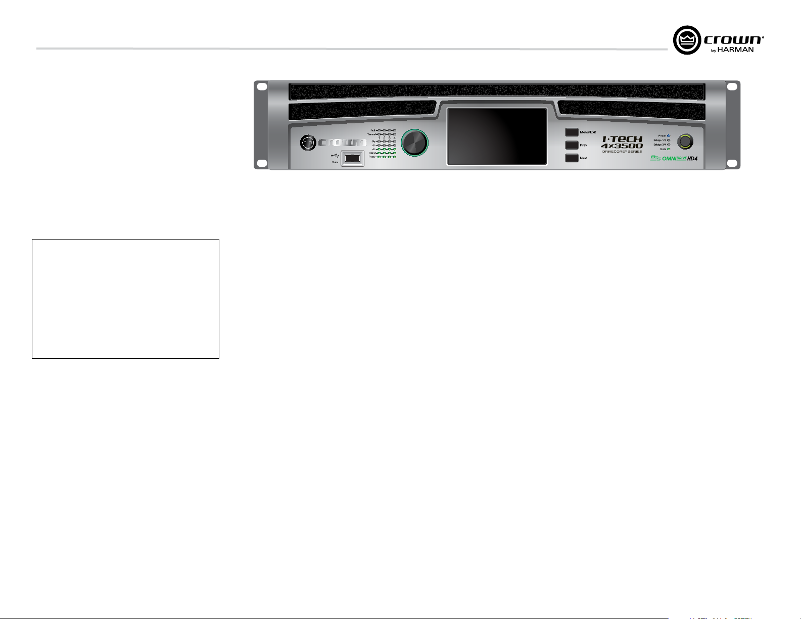
The Crown® I-Tech HD DriveCore Series offers
amazing power, light weight and ease of use for
touring sound applications. Unlike other
amplifiers, it includes onboard high-definition
DSP, a 4.3” LCD TFT Capacitive Touchscreen,
and a built-in network connection.
Modern power amplifiers are sophisticated
pieces of engineering capable of producing
extremely high power levels. They must be
treated with respect and correctly installed if
they are to provide the many years of reliable
service for which they were designed.
In addition, I-Tech Series amplifiers include a
number of features which require some
expla nation before they can be used to their
maxi mum advantage.
Please take the time to study this manual so that
you can obtain the best possible service from
your amplifier.
1.1 Features
• Global Power Supply with PFC (Power Fac tor
Correction) works anywhere in the world.
• High power density, up to 12,000 watts in a
2U chassis.
• Output voltage of 185Vpk provides clean
transient peaks.
• 6th-generation patented Class I (BCA® with
Drivecore Technology) cir cuitry couples power
efficiently to the load and provides low AC
current draw.
• Onboard high-denition analog devices
®
Sharc
processor DSP with 24-bit, 192 kHz
SHARC A/D and D/A converters. Advanced IIR
filters and linear-phase FIR filters.
• Pushbutton presets simplify setup. Custom
presets for various loudspeakers can be
down loaded.
• AES3 digital audio input with V-Drive.
• EtherCon® Ethernet con nector for HiQnet™
control or CobraNet digital audio transport.
This “Single Plug” connection allows HiQnet
protocol and CobraNet digital audio, and
VDrive through the same CAT 5 cable.
• LCD Control Screen is used to adjust the
amplifier’s attenuation and muting, configure
the amp, set up and view error monitoring, and
recall DSP presets to reconfigure the amp for
various applications.
• Comprehensive array of indicators provide
accurate diagnostics: Power, Data, along with
Ready, Signal, Clip, Thermal and Fault for each
channel.
• AC mains indicator in power switch glows
green when AC power is present.
• Front-panel USB connector accepts a USB
drive to transfer presets from the drive to the
amplifier DSP, and vice versa. This feature also
allows you to update the amplifier’s firmware.
• Light weight due to aluminum chassis,
spe cial internal construction, switching power
supply and patented class-I output stage with
DriveCore Technology.
• Thermal management controller and two
dis crete thermal zones with variable-speed fans,
forced-air cooling.
• Advanced protection circuitry guards against:
shorted outputs, DC, mismatched loads,
general overheating, under/over volt age, highfrequency overloads and internal faults.
• Five-Year, No-Fault, Fully Transferable
Warranty completely protects your investment
and guarantees its specifications.
1.2 How to Use This Manual
This manual provides you with the necessary
information to safely and correctly setup and
operate your amplifier. It does not cover every
aspect of installation, setup or operation that
might occur under every condition. For
addi tional information, please consult the
online help in System Architect software,
Crown’s Amplifier Application Guide, I-Tech
Application Guide (available online at www.
crownaudio.com), Crown Technical Sup port,
your system installer or retailer.
We strongly recommend you read all
instruc tions, warnings and cautions contained
in this manual. Also, for your protection, please
send in your warranty registration card today.
And save your bill of sale — it’s your official
proof of purchase.
page 5
Page 6
2 Setup
.
8.9 cm
43.1 cm
I-Tech HD DriveCore Series Power Ampliers
2.1 Unpack and Install Your
Amplier
Please unpack and inspect your amplifier for
any damage that may have occurred during
transit. If damage is found, notify the
transpor tation company immediately. Only you
can ini tiate a claim for shipping damage. Crown
will be happy to help as needed. Save the
shipping carton as evidence of damage for the
shipper’s inspection.
We also recommend that you save all packing
materials so you will have them if you ever need
to transport the unit. Never ship the unit
without the factory pack.
YOU WILL NEED (not supplied):
• Input wiring cables
• Output wiring cables
• Ethernet cables
• Rack for mounting amplier (or a stable
surface for stacking)
WARNING: Before you start to set up
your amplifier, make sure you read and
observe the Important Safety Instructions found at the beginning of this
manual.
CAUTION: Before you begin, make sure
your amplifier is disconnected from the
power source, with the power switch in
the “off” position and all level controls
turned completely down (counterclockwise).
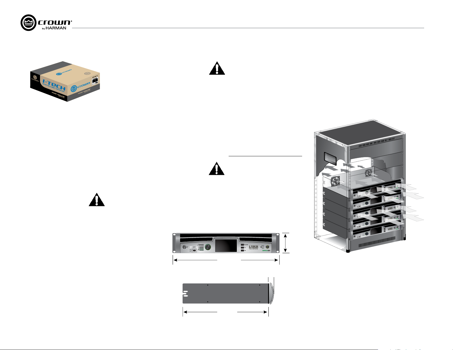
Use a standard 19-inch (48.3 cm)
equipment rack (EIA RS-310B). See
Figure 2.1 for ampli fier dimensions.
You may also stack amps without using a
rack.
NOTE: When transporting, amplifiers should be
supported at both front and back.
MAGNETIC FIELD
CAUTION! Do not locate sensitive high-gain
equipment such as preamplifiers or tape decks
directly above or below the unit. Because this
amplifier has a high power density, it has a
strong magnetic field which can induce hum
into unshielded devices that are located nearby.
The field is strongest on the right side and right
bottom of the amplifier (facing the amplifier).
If an equipment rack is used, we recommend
locating sensitive equipment at least 20 cm
(8 inches) away from the amplifier.
When using an equipment rack, mount units
directly on top of each other. Close any open
spaces in rack with blank panels. DO NOT block
front or rear air vents. The side walls of the rack
should be a minimum of two inches (5.1 cm)
away from the amplifier sides, and the back of
the rack should be a minimum of four inches
(10.2 cm) from the amplifier back panel.
Figure 2.2 illustrates standard amplifier airflow.
page 6
3.5 In
19 In.
48.3 cm
1.5 In.
16.95 In.
Figure 2.1
Dimensions
3.8 cm
Figure 2.2 Airow
Operation Manual
Page 7
I-Tech HD DriveCore Series Power Ampliers
A
NAL
OG
INPUT
S
CH1
CH2
CH3
CH4
C
H
3
/4
CH
1/
2
DIG
ITAL INPUT AES3
NNN
ETETETWWW
OOO
RRR
KKK
COCOCO
NDNDND
...
DADADATATATA
PRPRPREEE
SSS
EEE
TTT
LLL
INININKKK
///
ACACACTTT
...
OO
UTPUTUTPUT
SS
CC
H1H1
CCHH22
DUDUALAL
BRIBRIDDGGEE
DUDUALAL
CCHH33
CCHH44
BRIBRIDDGGEE
DUDUAALL
DUDUAALL
EE
GG
. U.. U.
SS
. . PAPAT.T.
OO
FFFF. . 5,5,65657,7,212199
505044
,,
34348 8 66
,,
909099
,,
32321 1 77
,,
282833
,,
373799
,5,55757,,
626222
7,7,
99
11
99
,,
998998
7,7,7777
88
,,
3232
4 4 7,7,55
22
1,1,
939366
LALA
SSSS
2 2
OO
UTPUUTPUT T WIWIRIRINN
GG
II
WW
AA
CCAAUU
UCUC
SKSK
GG
MUMUSS
2 Setup
2.2 Connecting to AC Mains
WARNING: The third (ground) prong of the supplied AC power
cord connector is a required safety feature. Do not attempt to
disable this ground connection by using an adapter or other
methods.
Amplifiers do not create energy. The AC mains voltage and current must be
sufficient to deliver the power you expect. You must operate your amplifier
from an AC mains power source with not more than a 10% variation above
or a 10% variation below the amplifier’s specified line voltage range and
within the specified frequency requirements (indicated on the amplifier’s
back panel label). If you are unsure of the output voltage of your AC mains,
please consult your electrician.
-T-TECHECH 4x4x35003500 || 23002300
TITIOON – N – TTOO REREDD
T T BEBE MAINMAINTATAINEDINED..
SSEMBLEDSSEMBLED ININ USUSAA
E E THTHE E RIRI
OFOF ELECTRICELECTRIC SHOCSHOCKK,, GROUNDINGROUNDIN
2.3 Wire Inputs and Outputs
2.3.1 Wiring basics
• Always use shielded wire for input wiring. The higher the density of the
shield (the outer conductor) the better. Spiral wrapped shield is not
recom mended.
• When using unbalanced lines keep the cables as short as possible. Avoid
lengths greater than 10 feet (3 meters).
• Do not run audio input cables together with high-level wiring such as
loudspeaker wires or AC cords. (This lessens the chance of hum and noise
being induced into the input cables.)
• Turn the entire sound system off before changing any connections.
Crown is not liable for damage incurred when any transducer or compo nent
is over driven.
THE CHANNEL 2 AND 4 INPUT IS IGNORED by default in Bridge Mono
mode. It can be summed using the input source selector.
For additional information on audio input wiring please refer to the Crown
Amplifier Application Guide available online at www.crownaudio.com. It
contains helpful information on preventing unwanted subsonic frequen cies,
radio frequency interference, ground loops, and feedback oscillation.
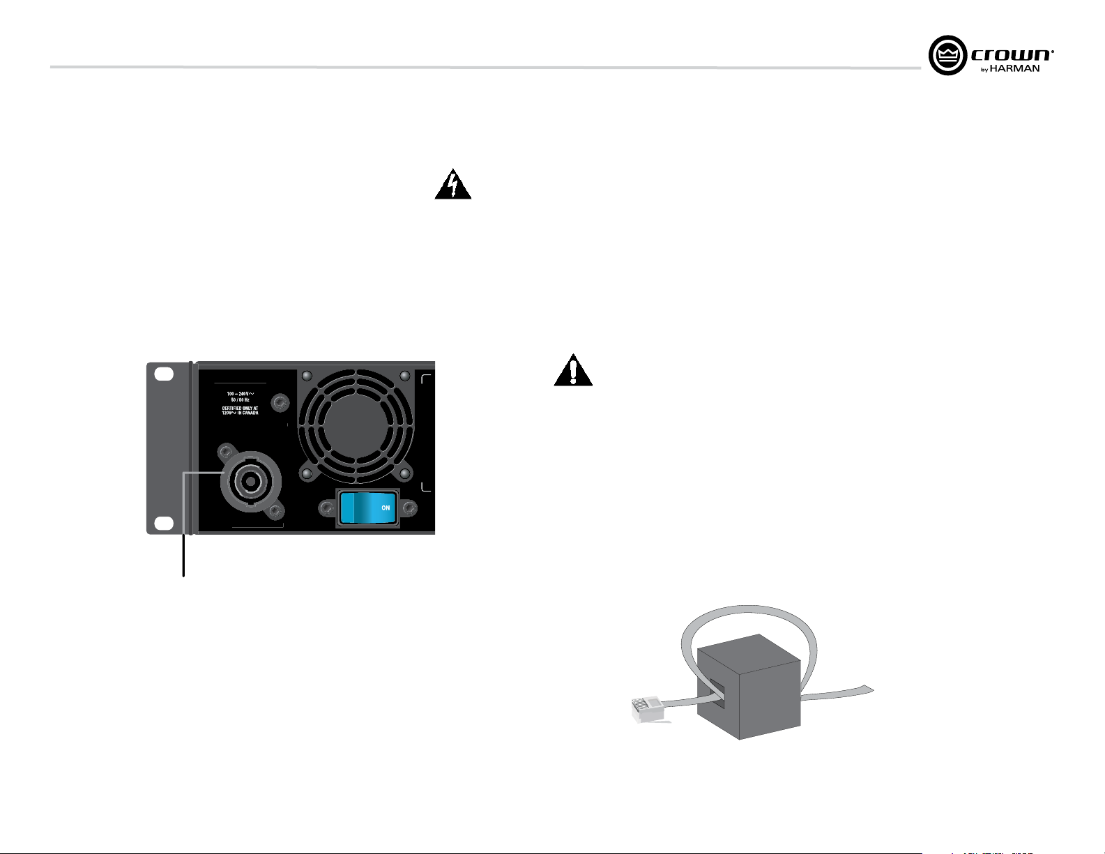
When using network connections, pass the CAT 5 cable five times through a
ferrite core (Figure 2.4), available from Crown Audio Inc. This is to ensure
compliance with emission regulations.
32A Neutrik® powerCON
Figure 2.4 Pass the CAT 5 Cable Five Times Through the Ferrite Core
Figure 2.3 Power Connector
Operation Manual
page 7
Page 8
2 Setup
OUTPUTS
CH1 CH2
DUAL
BRIDGE
DUAL
CH3CH4
BRIDGE
DUAL DUAL
I-Tech HD DriveCore Series Power Ampliers
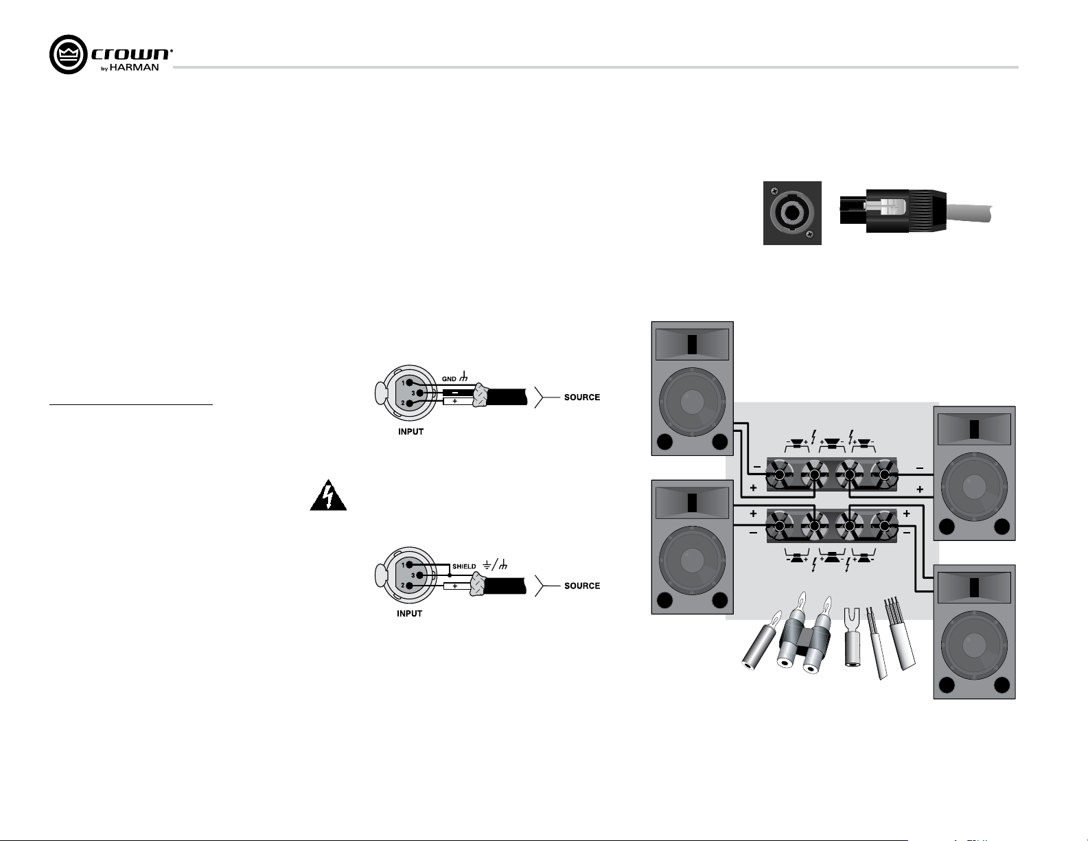
2.3.2 Choose Input Wire and Connectors
Crown recommends using pre-built or professionally wired,
bal anced line (two-conductor plus shield), 22-24 gauge cables
and connectors. Use 3-pin male XLR connectors.
Unbalanced line may also be used but may result in noise over
long cable runs.
Figure 2.5 shows connector pin assignments for balanced analog
wiring or AES3 digital wiring. The use of standard analog cable
with AES3 will result in diminished performance. For best results,
110 ohm shielded twisted-pair cable for AES3 signals is highly
recommended. Figure 2.6 shows connector pin assignments for
unbalanced analog wiring.
If multiple connectors are needed for AES3 distribution from a
single AES3 source, the following shows the number of AES
connections in parallel based on AES3 switching frequency.
Frequency # of Connections
96kHz 4 AES3 Pairs
48kHz 8 AES3 Pairs
44.1kHz 8 AES3 Pairs
***Please note with good quality 110 ohm shielded digital cable,
it is possible to obtain a higher number of connections than stated
here. It is up to the user to test this based on their use case. The
connections stated here are based on worst case analysis.
CAUTION – SHOCK HAZARD: Potentially lethal voltages
exist at the output connectors when the amplifier is
turned on and is passing a signal.
Using the guidelines below, select the appropriate size of wire
based on the distance from amplifier to speaker.
Distance Wire Size
up to 25 ft. 16 AWG
26-40 ft. 14 AWG
41-60 ft. 12 AWG
61-100 ft. 10 AWG
Figure 2.5
Balanced Analog Input Connector Wiring or
AES3 Digital Connector Wiring
Figure 2.7
Left: Speakon
Right: Speakon
®
Output Connector on Back Panel
®
Cable Connector
NOTE: Custom wiring should only be performed by qualified
per sonnel.
2.3.3 Choose Output Wire and Connectors
Crown recommends using pre-built or professionally wired, highquality, two-, four-, or eight-conductor, heavy gauge speaker wire
and connectors. Use Class 2 output wiring. You may use a 4-pole
Speakon® connector (Figure 2.7) or banana plugs, spade lugs, or
bare wire for your output connectors (Figure 2.8). To prevent the
possibility of short circuits, wrap or otherwise insulate exposed
loudspeaker cable connectors.
page 8
Figure 2.6 Unbalanced Analog Input Connector Wiring
Figure 2.8
Binding Post Connections
Operation Manual
Page 9
I-Tech HD DriveCore Series Power Ampliers
Channel 1
Loudspeaker
Channel 1
Loudspeaker
Channel 2
Loudspeaker
Channel 2
Channel 1
2 Setup
101-150 ft. 8 AWG
151-250 ft. 6 AWG
CAUTION: Never use shielded cable for output wiring.
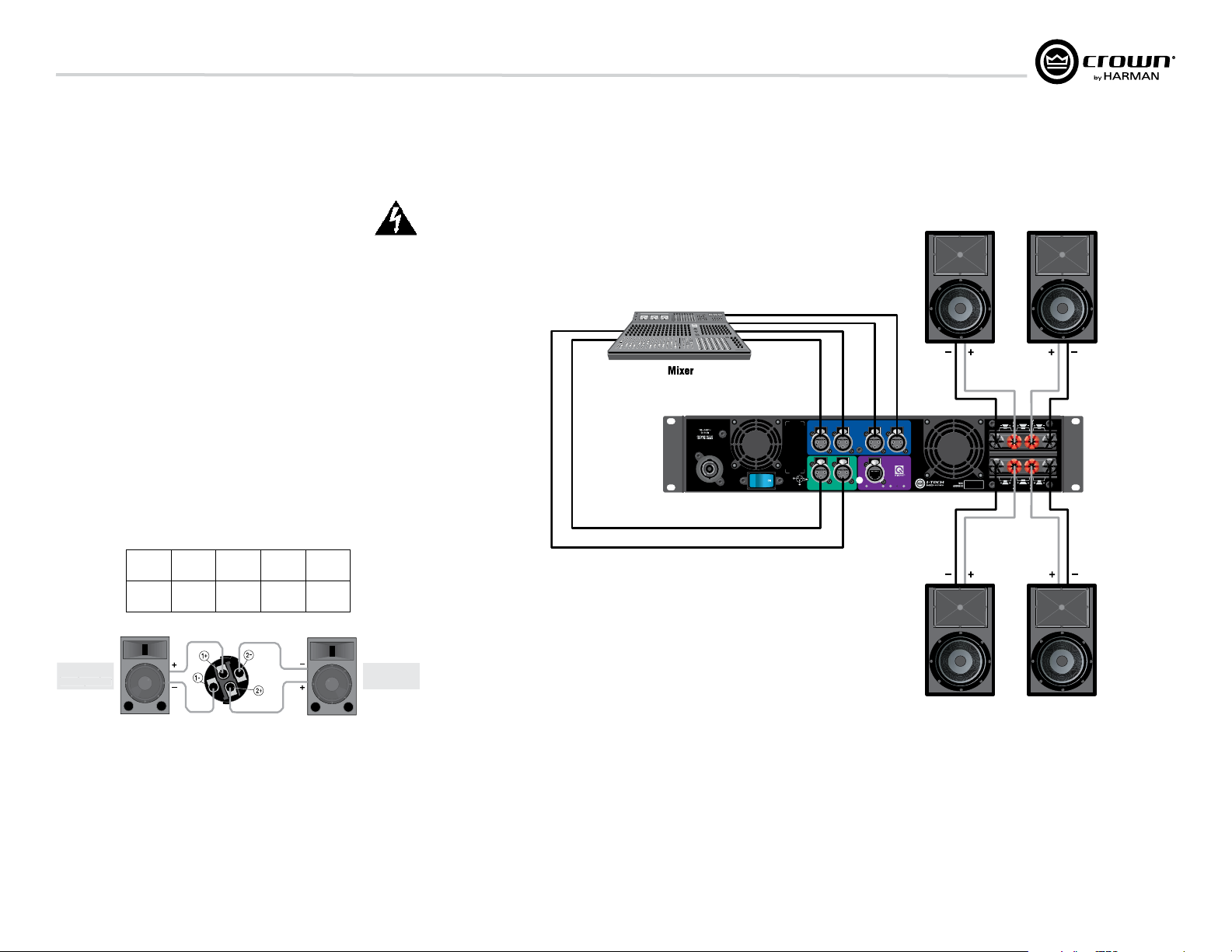
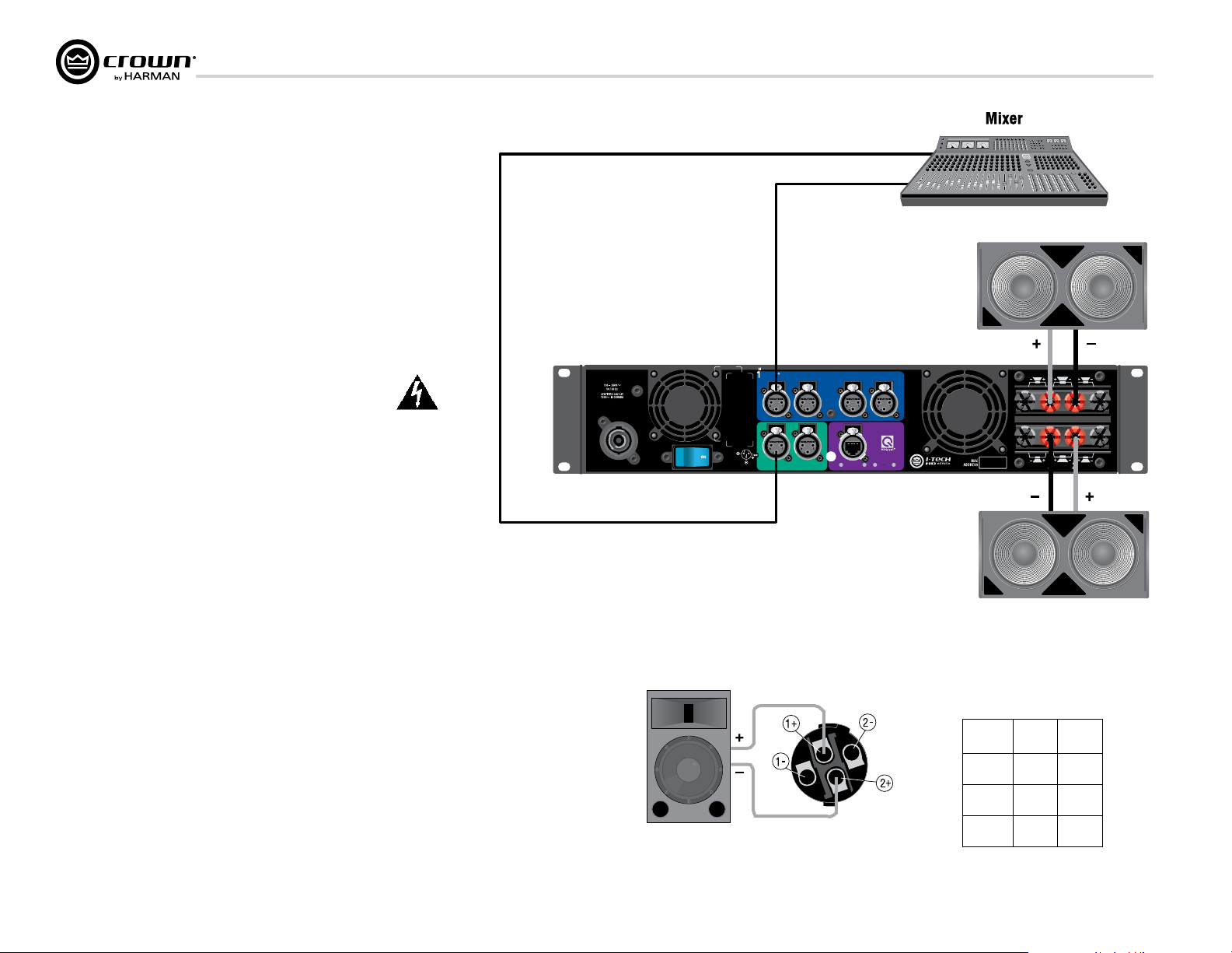
2.3.4 Stereo Mode Wiring
Typical input and output wiring is shown in Figure 2.9.
IMPORTANT: Turn off the amplifier and unplug its power cord.
INPUTS: Choose one of these options:
• Connect analog input wiring for all channels.
• Connect AES3 digital signal to the AES3 connectors.
OUTPUTS: Maintain proper polarity (+/–) on output connectors. Use
Class 2 output wiring.
Figure 2.9 shows how to wire stereo speakers to the binding posts.
Con nect Channel 1 loudspeaker’s positive (+) lead to Channel 1 positive
(red) terminal of amp; repeat for negative (–). Repeat Channel 2 wiring as
for Channel 1.
®
To wire stereo speakers to the Speakon
connectors, use this method:
I-TECH 4x3500 | 2300W
CAUTION – TO REDUCE THE RISK
OF ELECTRIC SHOCK, GROUNDING
MUST BE MAINTAINED.
ASSEMBLED IN USA
Channel 1
Channel 2
ANALOG
CH1CH2 CH3CH4
INPUTS
CH
3/4
CH
1/2
DIGITAL INPUT AES3
COND.
Channel 4
Channel 3
OUTPUTS
CH1CH2
BRIDGE
DUAL
DUAL
REG. U.S. PAT. OFF. 5,657,219
6,504,348 6,909,321 7,283,379
7,557,622 7,919,998 7,778,324 7,521,936
NETWORK
DATA PRESET
LINK/
ACT.
CLASS 2 OUTPUT WIRING
BRIDGE
DUAL DUAL
CH3CH4
Stereo Wiring Method 1: Use Top Speakon® Only
PIN 1+ 1– 2+ 2–
CH 1+ 1– 2+ 2–
Figure 2.10 Wiring Two Stereo Speakers
to the Top Speakon
Operation Manual
Table 1
®
Connector
AES 1+2
AES 3+4
Figure 2.9
System Wiring,
2 x Stereo Mode
Channel 4Channel 3
page 9
Page 10
2 Setup
I-Tech HD DriveCore Series Power Ampliers
AES
Table 1 and Figure 2.10: Wire one Speakon® cable connector to two speakers. Insert
the Speakon® cable connector into the amplifier’s top Speakon® connector.
2.3.5 Bridge-Mono Mode
Overview: Turn on the amp, enable Bridge-Mono mode using the LCD Control
Screen, turn off the amp, wire it, and turn it back on.
1. Be sure that no cables are connected to the amplifier. Turn on the front-panel power
switch. The LCD Control Screen will light up.
2. Under the LCD Control Screen, press the Menu/Exit button. Press the Next
button until you see OUTPUT MODE on the screen. If N/A is displayed, OUTPUT
MODE is locked via software. If LOCKOUT is displayed, all the LCD screens are
locked via software.
3. Press the Encoder knob to select BRIDGE MONO. Press the knob again to confirm
your choice. Press Menu/Exit. Turn down both level controls (Encoder) until you
reach maximum attenuation.
4. IMPORTANT: Turn off the amplifier and unplug its power cord.
INPUTS: There are three ways to connect an input signal to the amplifier
(Figure 2.11):
• Connect an analog signal source to the Channel-1 and/or Channel-3 amplier
input.
• Connect an AES/EBU digital signal source to the Digital Input IN connector.
NOTE: Crown provides a reference of wiring pin assignments for commonly used
connector types in the Crown Amplifier Application Guide available at
www.crownaudio.com.
OUTPUTS: Use Class 2 output wiring. There are two ways to wire the amplifier output
connectors for Bridge-Mono mode:
1) Wire the speaker across the red binding post channels 1/2 and 3/4 (Figure 2.11).
Do not use the black binding posts when operating in Bridge-Mono mode.
NOTE: In Bridge-Mono mode, the Channel 1 Level control sets the level;
the Channel 2 Level control is defeated. All Channel 2 objects and
controls are hidden and disabled. In this mode, the Channel 3 Level
control sets the level; the Channel 4 Level control is defeated.
Figure 2.11
System Wiring,
2 x mono mode
I-TECH 4x3500 | 2300W
CAUTION – TO REDUCE THE RISK
OF ELECTRIC SHOCK, GROUNDING
MUST BE MAINTAINED.
ASSEMBLED IN USA
Analog
CH
3/4
ANALOG
INPUTS
COND.
CH1CH2 CH3CH4
CH
1/2
DIGITAL INPUT AES3
OUTPUTS
CH1CH2
BRIDGE
DUAL
REG. U.S. PAT. OFF. 5,657,219
6,504,348 6,909,321 7,283,379
7,557,622 7,919,998 7,778,324 7,521,936
NETWORK
DATA PRESET
LINK/
ACT.
CLASS 2 OUTPUT WIRING
CH3CH4
DUAL DUAL
DUAL
BRIDGE
Table 2
®
Speakon
Wiring for Bridge-Mono
PIN 1+ 2+
SPKR
+ –
page 10
Figure 2.12
Mono Wiring Using Both
PIN
SPKR
3+ 4+
+ –
Operation Manual
Page 11
I-Tech HD DriveCore Series Power Ampliers
3 HARMAN GreenEdge -Going ‘Green’ without compromise
3.1 Going ‘Green’
Going ‘Green’ is no longer an option – it’s a necessity. Protecting the world
we live in against adverse climate change is a major objective of socially
responsible governments, businesses and individuals everywhere.
Reducing energy consumption is fundamental to the reduction of
greenhouse-gas emissions and is likely to impact various elements of our
lifestyle. Maintaining the quality of our lifestyle, while improving the
environment, is a challenge addressed by the HARMAN GreenEdge
advanced technology initiative.
HARMAN’s passion for innovative engineering remains dedicated to its goal
of acoustic excellence for all of its products. HARMAN’s loyal customers
never need to fear the loss of performance from going ‘Green’ – in fact, the
new range of GreenEdge audio systems enhance performance and acoustic
qualities. HARMAN continues to drive the importance of ‘the listening
experience’ while caring for the world we share.
3.2 The Sound of Efciency
HARMAN’s Research and Development teams are implementing highly
innovative engineering, design and manufacturing processes across its
range of world-class branded audio and infotainment products. The
GreenEdge technology initiative allows partners to take advantage of
Eco-Friendly, energy-saving benefits such as:
Weight Savings -When compared to traditional, non-switching
amplifiers, the I-Tech HD Series weighs an average of 50 lbs
(22.68kg) less. Less weight benefits the consumer by reducing
shipping costs and benefits the environment by reducing emissions
from vehicles because the shipper is able to either reduce the
amount of vehicles needed to transport the goods or the vehicle is
not running up to its weight limits resulting in less fuel economy.
High-Efciency Designs – The patented Universal Power
Supply with Power Factor Correction combined with the patented
Class-I PWM output stage of the I-Tech HD series amplifiers
provides greater than 90% efficiency when ran at 100VAC to 240VAC
and all voltage in between.
Power Savings – The I-Tech HD Series has both manual and
automatic standby modes that put the amplifier into a low AC current
draw state when not in use. When in this mode, the I-Tech HD series
draws an average of 100W of power greatly reducing your power
bills.
Environmental Responsibility – By integrating HARMAN
GreenEdge systems into your business model, you are promoting
Eco-Friendly energy saving initiatives and reducing your impact on
the enviorment.
3.3 Green Savings
Here’s an example of the energy savings offered by Crown’s Class-I
tour products:
Class-I Amplifiers v. MA5002VZ in Touring Applications
• If Crown shipped 13,500 IT4000/MA5000/IT5000HD
• If we had shipped 13,500 MA5002VZs in their place, the
numbers would look like this:
MA5002VZ
Number of Units 13,500 13,500
Total Weight 519.8 tons 189 tons
1 hour of Electricity Usage 2.52kWh 1,602kWh
1 year of Electricity Usage 18,370,800 kWh 11,678,580 kWh
Electricity Savings:
• ~6,692,220 kWh
• Enough to power ~370 households annually!
Weight Savings (Freight):
• Reduces ~400 Metric tons of greenhouse gas annually
• About the same as taking 75 cars off the road
Class-I Tour Amp
(IT4000, MA5000i, IT5000HD)
Operation Manual
page 11
Page 12
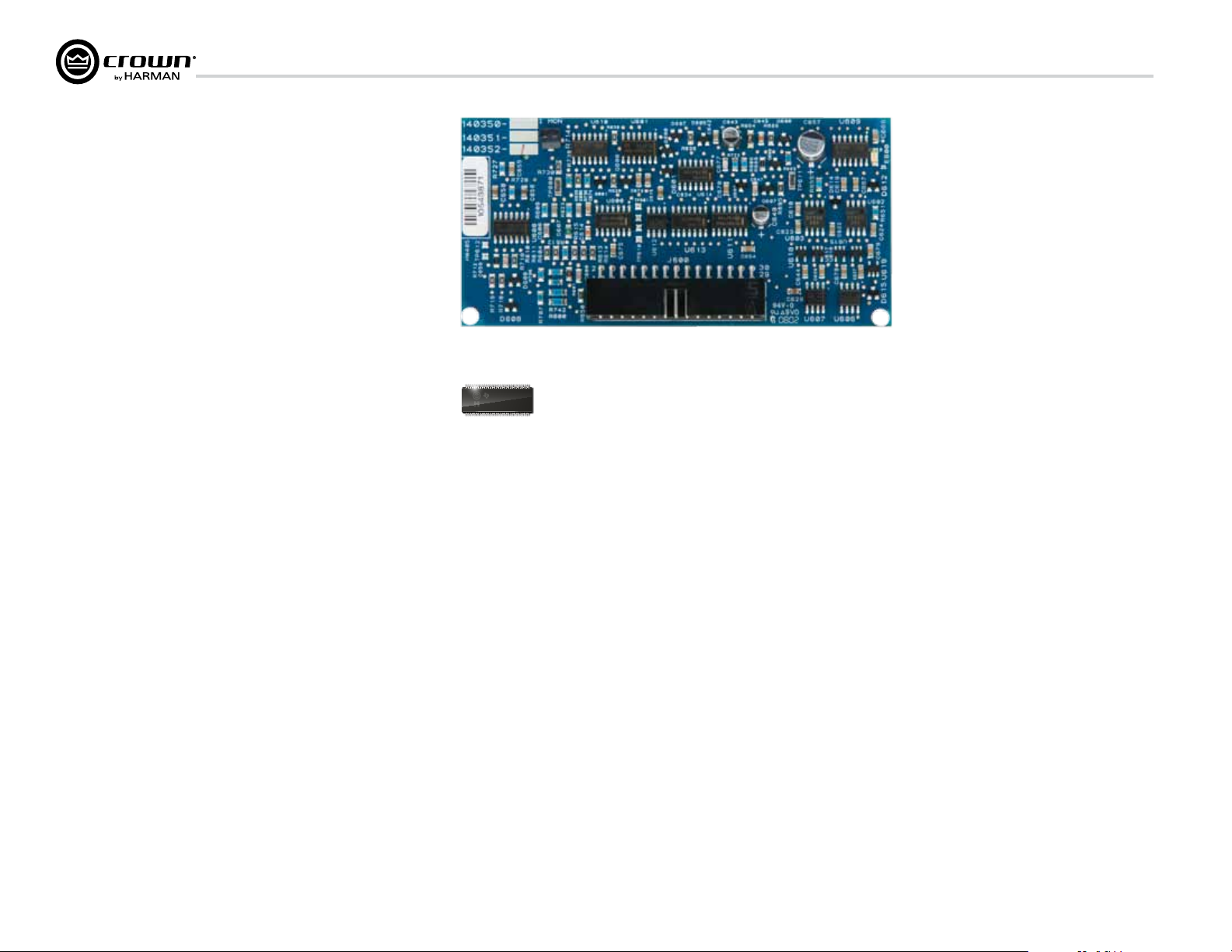
4 Integrated DriveCoreTM Technology
Class D and Class I amplifiers are notable for extraordinarily high
efficiency and being well suited for driving difficult reactive loads such
as subwoofers.
Crown engineers developed DriveCore™ Technology – a proprietary
hybrid analog-digital integrated circuit (IC) developed with Texas
Instruments that drives the “front end” of the Class D or Class I output
stage. Over 60 years of Crown’s design knowledge and experience went
into the development of this technology resulting in truly remarkable
benefits.
DriveCore™ Technology provides an extremely wide-tolerance with
regards to sagging or “dirty” AC line conditions providing consistent
performance without affecting audio quality. This means that your
performance will not be compromised by fluctuating generator power
or overloading by lighting rigs, backline gear, etc.
In addition, DriveCore™ Technology’s patented feedback and PWM
modulation circuits enable fast recovery on peak transients, accurate
reproduction of low-level detail, and precise tracking of lowfrequencies at high power levels for maximum subwoofer output.
Figure 4.1 I-Tech HD 2 Channel Front End Board
07CYDJKL
SN61112B5
Figure 4.2 Ruby Chip (Actual Size)
I-Tech HD DriveCore Series Power Ampliers
page 12
Operation Manual
Page 13
I-Tech HD DriveCore Series Power Ampliers
Level
s/Mut
e
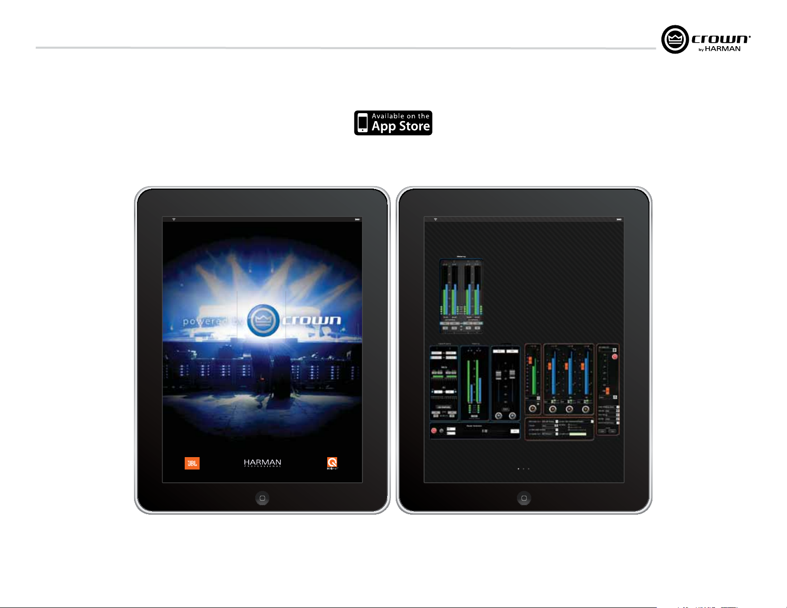
5 Powered by Crown
This I-Tech HD Series amplifier is compatible with the Powered by Crown app.
For more information visit:
http://www.crownaudio.com/mobileapplications/index.htm
iPad iPad
The New System Control App from Crown,
Available at the Apple App Store.
+ Instantly connect to your Crown networked amps; just p lug
your amps into any wireless router, watch the amps
auto-populate, and you have full control of every thing
+ Watch over your entire rig using your IPhone or IPad, anywhere
in the venue - intuitive control panels allow you to monitor input
levels, output levels, thermal conditions - anything you nee d
+ Need to limit control or see something special? Choose any
controls you want using System Architect custom panels; then
easily import them using ITunes
+ Use it with CTs, I-Tech, I-Tech HD, and Macro Tech I series (CTs
requires network PIP)
Levels/Mute
Input Signal GeneratorLOW MID HIGH
Available right now, download instantly from the Apple App Store.
Operation Manual
Visit crownaudio.com for more information
page 13
Page 14
6 Operation
I-Tech HD DriveCore Series Power Ampliers
6.1 Protecting Your Speakers
It’s wise to avoid clipping amplifier signals at the input and output. Not
only does clipping sound bad, it can damage loudspeakers. To prevent
clipping, use System Architect software’s Level Max suite to enable or
display the peak voltage limiter and average power limiter in your
amplifier’s built-in DSP. That way, no matter how strong a signal your
mixer produces, the amplifier output will not clip. Set the limiter
threshold so that at full level no components in the audio signal chain
are clipping, the amplifier input and output is not clipping, and the
attached loudspeakers at properly protected according to the mnfg’s
rec’d specifications.
Also, avoid sending strong subsonic signals to the amplifier. Highlevel, low-frequency signals from breath pops or dropped microphones can blow out drivers. To prevent subsonic signals, use one of
these methods:
• Insert a highpass lter between mixer output and amplier input (or
between mixer and limiter).
• Use the I-Tech’s onboard DSP to set up a highpass lters.
• Switch in highpass lters at your mixer. Set the lter to as high a
fre quency as possible that does not affect your program. For example,
try 35 Hz for music and 75 Hz for speech. On each mixer input channel,
set the filter frequency just below the lowest fundamental frequency of
that channel’s instrument.
• Note: An amplier reproduces the signal present on the input.
Therefore, if you send clipped or squared wave signals to the input, it
will recreate this on the output possibly damaging your loudspeakers.
6.2 Startup Procedure
When first turning on your amplifier, follow the procedures in the
Quick-Start Guide on page 4 (stereo) or page 5 (bridge-mono).
If you ever need to make any wiring or installation changes, don’t for get
to disconnect the power cord.
For help with determining your system’s optimum gain structure
(sig nal levels) please refer to the Crown Amplifier Application Guide,
available online at www.crownaudio.com.
6.3 Precautions
Your amplifier is protected from internal and external faults, but you
should still take the following precautions for optimum performance
and safety:
1. Before use, your amplifier first must be configured for proper
operation, including input and output wiring hookup. Improper
wiring can result in serious operating difficulties. For information
on wiring and configuration, please consult the Setup section of
this manual or, for advanced setup techniques, consult Crown’s
Amplifier Application Guide available online at
www.crownaudio.com.
2. Use care when making connections, selecting signal sources and
controlling the output level. The load you save may be your own!
3. Do not short the ground lead of an output cable to the input signal
ground. This may form a ground loop and cause oscillations.
4. WARNING: Never connect the output to a power supply,
battery or power main. Electrical shock may result.
5. Tampering with the circuitry, or making unauthorized circuit
changes may be hazardous and invalidates all agency listings.
6. Do not operate the amplifier with the red Clip LEDs constantly
flashing.
7. Do not overdrive the mixer, which will cause clipped signal to be
sent to the amplifier. Such signals will be reproduced with extreme
accuracy, and loudspeaker damage may result.
8. Do not operate the amplifier with less than the rated load
imped ance. Due to the amplifier’s output protection, such a
configura tion may result in premature clipping and speaker
damage.
9. CAUTION – SHOCK HAZARD: Potentially lethal voltages
exist at the output connectors when the amplifier is
turned on and is passing a signal.
Remember: Crown is not liable for damage that results from
overdriv ing other system components.
page 14
Operation Manual
Page 15
I-Tech HD DriveCore Series Power Ampliers
6 Operation
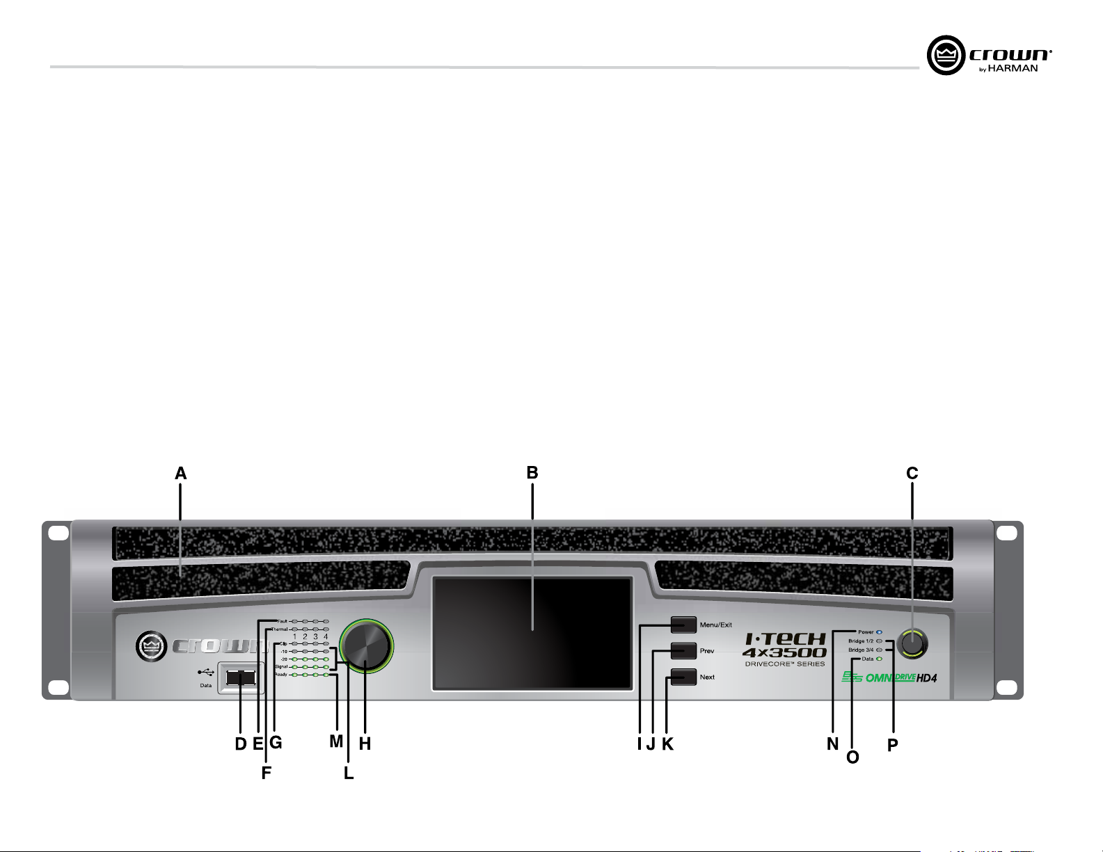
6.4 Front Panel Controls and Indicators
Many of these functions can be disabled using
Blackout Mode (a selection in the Advanced
Menu, Section 7.2).
A. Cooling Vents
Front-to-rear forced airflow through foam dust filter
B. LCD Control Screen
Integrated 4.3” color touchscreen LCD with
backlight, controls ampli fier setup and operation.
The LCD Control Screen and its controls let the user
adjust the amplifier’s attenuation and muting,
con figure the amp, set up and view error monitoring
(such as temperature and load supervision), and
recall DSP presets.
C. Power Switch
Push-on/push-off switch glows green when AC
power is present at the power cord and the amplifier
circuit breaker is in the “on” position.
D. USB 2.0 Connector
Accepts a USB drive to transfer presets, device files,
and update firmware from the drive to the amplifier
DSP, and vice versa.
E. Fault Indicator
Red LED, one per channel, flashes when the
ampli fier output channel has stopped operating.
Usually this means that the amplifier must be
serviced.
F. Thermal Indicator
Red LED, one per channel, illuminates when the
channel has shut down due to thermal stress or
overload.
G. Clip Indicator
Red LED, one per channel, illuminates when the
channel’s output signal reaches the onset of audible
clipping. The Clip Indicator also will illuminate
dur ing Thermal Level Control (TLC) limiting. The
Clip Indicator can be turned off during Blackout
mode.
H. Level Control (Encoder)
Speed-sensitive, 0.5 dB steps, range 0 to –100 dB.
This knob affect the Channel 1-4 output levels. Also
Menu items and adjust parameter values that are
displayed on the LCD control screen.
I. Menu/Exit Button
“Menu” enters the main menu. “Exit” leaves the
menu.
J. Prev Button
Selects the previous item in the menu.
K. Next Button
Selects the next item in the menu.
L. Signal Indicators
These can be disabled during Blackout mode. Three
green LEDS per channel indicate the ampli fier’s input
and output signal levels. From top to bot tom the
LEDs are
–10 dB: amplifier output is 10 dB below clipping.
–20 dB: amplifier output is 20 dB below clipping.
Signal: selected input signal is above –40 dBu.
M. Ready Indicator
Green LED, one per channel, illuminates when the
channel is initialized and ready to produce audio
out put.
N. Power Indicator
Blue LED indicates amplifier has been turned on and
AC power is available. The LED will flash when the AC
line voltage is 15% above or below the nominal rated
range. This indicator can be turned off in Blackout
mode.
O. Data Indicator
Yellow LED indicates network data activity. Data
indicator flashes only when the amplifier is polled for
data, or is polled to see whether it is online. This
indicator can be turned off in Blackout mode.
P. Bridge Mode Indicator
Yellow LED illuminates when the amplifier is set to
Bridge-Mono mode.
Operation Manual
Figure 6.1 Front Panel Controls and Indicators
page 15
Page 16
6 Operation
ANALOG
INPUTS
CH1 CH2CH3 CH4
CH
3/4
CH
1/2
DIGITAL INPUT AES3
NETWORK
COND.
DATA PRESET
LINK/
ACT.
I-TECH 4x3500 | 2300W
ASSEMBLED IN USA
CAUTION – TO REDUCE THE RISK
OF ELECTRIC SHOCK, GROUNDING
MUST BE MAINTAINED.
OUTPUTS
CH1CH2
DUAL
BRIDGE
DUAL
CH3CH4
BRIDGE
DUAL DUAL
REG. U.S. PAT. OFF. 5,657,219 6,504,348 6,909,321
7,283,379 7, 557,622 7,919,998 7,778,324 7, 521,936
CLASS 2 OUTPUT WIRING
I-Tech HD DriveCore Series Power Ampliers
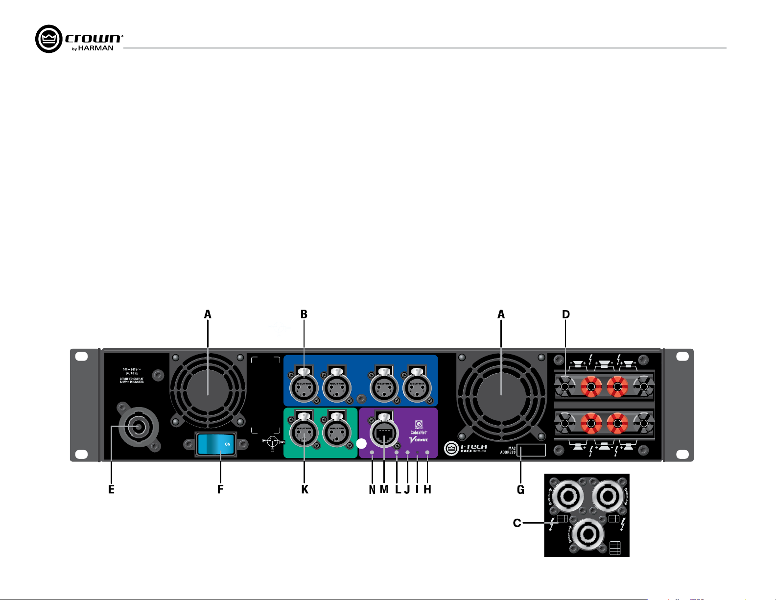
6.5 Back Panel Controls, Indica tors
and Connectors
A. Fans
Provide front-to-back forced airflow for cooling.
ANALOG INPUTS SECTION
B. Balanced Analog XLR Inputs
A 3-pin female XLR connector for each channel.
OUTPUTS SECTION
C. Speakon® Output Connectors
Two high-current, 50A Neutrik® Speakon® NL4MLP
(mates with NL4FC and NL4), for channels 1+2 or
3+4 and one NLT8 for channels 1 thru 4. Class 2
output wiring required.
These two connectors accept 2-pole or 4-pole
Speakon® connectors. See Figures 2.5 through 2.10
and Tables 1, 2 and 3 for connector wiring. The top 2
speakon connectors are wired each for stereo
operation off of one connector, the bottom NL8
speakon connection is for four way operation off
of one connector.
D. Binding Post Output Jacks
One pair per channel of high-current, 60A
color-coded binding posts. Accepts banana
plugs, wire or spade lugs.
E. Power Cord Connector
32 amp PowerCon
®
AC Inlet. Voltage range is
indicated above IEC inlet.
F. Reset Switch/Circuit Breaker
If the current draw of the amplifier exceeds safe
limits, this breaker automatically disconnects
the power supply from the AC mains. The switch
resets the circuit breaker.
G. MAC Address
This specific amplifier’s network identifier that is
burned into its firmware.
H. Preset Indicator
LED flashes to signal the number of the current preset if active.
LED is green if the preset values have not been changed once
loaded. LED is yellow if the preset values have been changed
since they were loaded.
I. Reset Button
To restore factory default settings: Press the Reset Button with a
thin, non-conductive object, then turn on amplifier power, and
continue to hold the reset button until the Preset light comes
on green (approximately 16 seconds)..
J. Data Indicator
Flashes yellow only when the amplifier is polled for data, or is
polled to see whether it is online.
DIGITAL INPUTS SECTION
K. AES/EBU Digital Input
This 3-pin female XLR connector accepts a dig ital signal in the
AES/EBU format.
It is not recommended to loop through more than four
amplifiers. If larger distribution of AES is needed, the use of
an AES distribution ampli fier is recommended.
NETWORKING SECTION
L. Link/Act Indicator
Shows net work activity.The LINK ACT LED illuminates when
the network port is connected and flashes when network
activity is detected.
M. Network Connector
This EtherCon
®
Ethernet connector is for networking.
Warning: Only connect to networks that remain inside the
building.
N. Cond Indicator
Turns on if the amplifier is set to be the CobraNet conductor.
The CobraNet conductor is a CobraNet node that provides
the master timing clock for the CobraNet digital audio
transport network.
page 16
Figure 6.2 Back Panel Controls and Connectors
OUTPUTS
CH1 / CH2 CH3 / CH4
+/–
1
1
+/–
2
2
+/–
3
+/–
4
CH1 / CH2
CH3 / CH4
+/–
1
+/–
2
+/–
3
+/–
4
1
2
1
2
3
4
Operation Manual
Page 17
I-Tech HD DriveCore Series Power Ampliers
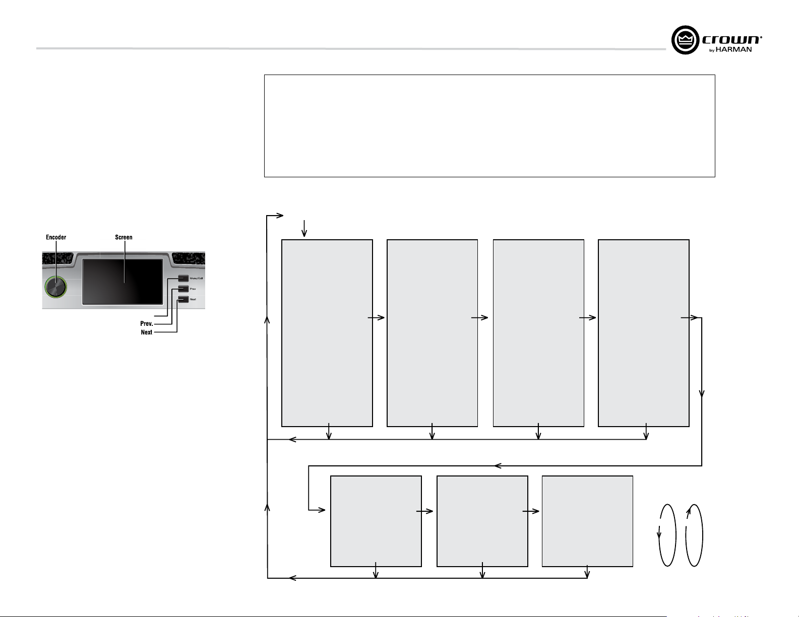
MENU TREE
tE
7 Advanced Operation
7.1 Introduction
The LCD Control Screen and its controls let you configure the
ampli fier and access many features that before were available only
through a remote computer. Also, you can recall DSP presets via
the front panel. (Some DSP parameters cannot be adjusted with
the LCD Control Screen. That is done in System Architect.)
Figure 7.1 shows the parts of the LCD Control Screen. Its
functions are described below. NOTE: Listed functions can also be
controlled in System Architect.
Here’s how to access the various menus and settings in the LCD
control screen:
Menu/Exit
Figure 7.1 Parts of the LCD Control Screen
• Starting from the Attenuation screen, press Menu/Exit to go to
the Menu screen.
• Press Next to go to the next item in the menu.
• Press Prev to go to the previous item in the menu.
• Turn or press the Encoder knob to change the value of a
dis played parameter.
• When you see a menu screen, push the knob once to see the
items in that menu. Or press Next to go to the next menu.
• Press Menu/Exit to leave the menu and return to the previous
screen at any time.
Some menu items require confirmation: after you request a change,
the display might say “Press and hold.” To confirm a change, press
and hold the Encoder knob. If you don’t want the change to occur
during a confirmation, turn the knob or wait five seconds.
The entire front panel or any selected screens can be locked out or
set to read only status using System Architect software. Locked-out
screens will either say “Lockout” or the individual parameter will
say “N/A”. If a change is attempted the screen will say “Changes
Disabled”.
Operation Manual
Touch Screen Functions
To Navigate:
Method 1
• Press Menu/Exit button to enter menu screen
• Use previous & next buttons to cycle through
menus
• Click with encoder wheel to select menu
Method 2
• Press menu/exit button to enter menu screen
• Press and drag with one finger to scroll through
• Tap with a finger on the menu to select
Menu Tree
As a handy reference, Figure 7.2 shows the menu structure of the LCD control screen. Starting from any Menu screen,
Attenuation - Mute - Lockout
Menu Button
PRESETS
Exit
ALERTS MENU
Amp Output Clip Errors
Next
Analog Input Clip Errors
Thermal Errors
Low/High Limit Load Errors
Sweep Load Monitoring Errors
Line Voltage Errors
Fan Errors
Clear All Error Logs
press an Encoder knob to go to the first selection in the Menu. You can loop through a menu’s selections using the Next
and Prev buttons. The Menu/Exit button returns you to the previous screen.
GENERAL PROPERTIES MENU
Sample Rate
Analog Input Sensitivity
Amp Mode
Locate
Channel Labels
Default Display View
Screen Configuration
Next
LED Meter Display Type
Manufacturing Information
Next
Exit ExitExit
Figure 7.2 The Menu Tree
menus
ADVANCED MENU
Attenuator Limits
Attenuator Link
Input Source Priorities Ch 1
Input Source Priorities Ch 2
Input Source Priorities Ch 3
Input Source Priorities Ch 4
Maximum Analog Input
Next
AES Input Trim
AES Input Status
Bandpass Gain
Output Polarity
Input Delay
Driver Delay
Clip Limiter
Pink Noise Generator
Sweep Load Monitoring
LevelMax Suite Menu
Limiter States
Peak Voltage Limiter
RMS Voltage Limiter
Transducer Thermal Limiter
Exit Exi
NETWORK CONFIGURATION MENU
Network Information
Manufacturing Information
HiQnet Node Address
Network Settings
Shortcuts:
• From the default display view, press and hold the
encoder wheel (with no channels selected) to mute
or unmute all channelss
• From any menu, press and hold the menu exit
button to return to the default display view
Next
COBRANET MENU
CobraNet Information
Next
CobraNet Input Ch 1
CobraNet Input Ch 2
CobraNet Input Ch 3
CobraNet Input Ch 4
CobraNet Foldback
CobraNet Conductor Priority
CobraNet Transport Latency
CobraNet Input Trim
MONITOR MENU
Global Metering
Load Monitoring
Thermal Percentage
Thermal Temperature
AC Line Voltage
Operating Time
Watts Output
ALL MENUS:
Next/Previous loops
xit
Next
Next
Prev
page 17
Page 18
7 Advanced Operation
I-Tech HD DriveCore Series Power Ampliers
7.2 Operation Examples
Operation Example 1
How to set the CH1 input sensitivity using the LCD Control
Screen:
1. After power-up, when the default display screen appears, press
Menu/Exit.
2. Press Next twice to reach the Advanced Menu, press the
encoder wheel to select.
3. Press Next once to reach the Analog Input Sensitivity menu,
then press the encoder wheel to select.
4. Tap on a channel and spin the encoder wheel to adjust the dB
gain for that channel, press Menu/Exit to deselect.
5. When finished, press and hold the Menu/Exit button to return
to the default display view.
Operation Example 2
How to monitor the Thermal Errors using the LCD Control Screen:
1. After power-up, when the default display screen appears, press
Menu/Exit.
2. Press Next four times to reach the Alerts Menu, press the
encoder wheel to select.
3. Press Next two times to reach the Thermal Errors menu, then
press the encoder wheel to select.
4. Tap on a channel to clear errors that channel, press Menu/Exit
to deselect.
5. When finished, press and hold the Menu/Exit button to return
to the default display view.
7.2.1 Basic Selections
Opening Screen: On power-up, the LCD Control Screen dis plays the
Crown logo. After a few seconds, the firmware version appears, then the
Attenuation screen appears.
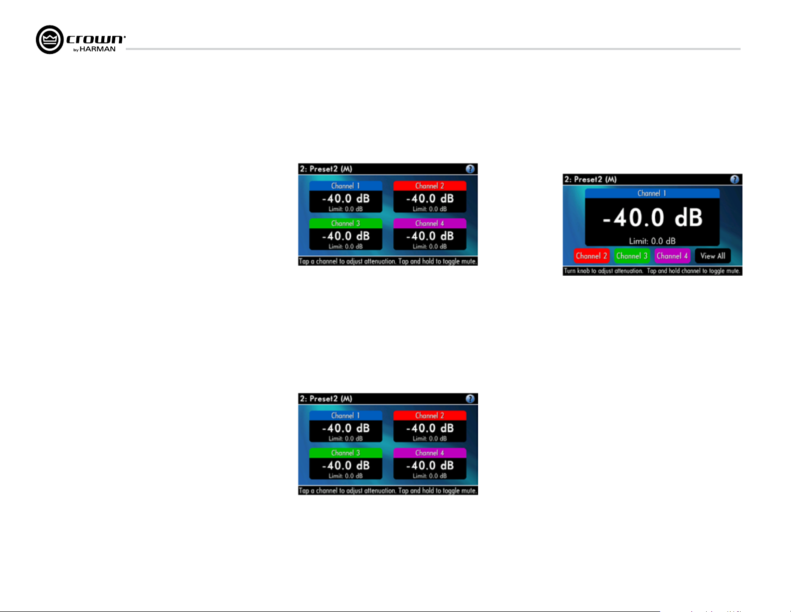
Attenuation and Bar Meters
This screen dis plays the attenuation in dB. To change atten uation tap a
channel and turn the Encoder. Attenuation changes 0.5 dB per detent
when you turn the Encoder slowly, and more when you turn the Encoder
quickly. The current preset name is displayed in the upper-right corner.
The (M) is explained on the next page under Presets.
If the attenuators for both channels are linked (in the Attenuator Link
screen, described later), the word LINK appears. (If there is an error in
the error log, an exclamation point appears at bottom center.)
Mute/Unmute (in the Attenuation screen)
• To mute a channel: The display will alternate between MUTE and the
attenua tion level. While the amplifier is muted, you can adjust
attenuation for each channel by tapping to select and turning the
Encoder knob.
• To unmute either channel: Press and hold for 1 second.
Front Panel Lockout (in the Attenuation screen)
The amplifier’s administrator can control access to menu mode and the
amplifier’s attenuators. This lockout can be done either by the front
panel buttons or by System Architect software.
To lock or unlock the menu with the front-panel buttons: press Next
and Prev simultaneously. To lock or unlock the menu with System
Architect software: go to the Tools Menu > Display Screen Security and
press the lockout button. If a specific parameter is protected, the
screen says “N/A” or “Change Disabled.”
Now let’s look at the function of each menu selection.
page 18
If the lockout is done from the software, the user can disable the lockout
only in the software, not by pressing the front-panel but tons.
If the menu is locked and you press any button or turn an Encoder, the
word “LOCKOUT” is displayed. If a specific parameter is protected, the
screen says “N/A” or “Change Disabled.”
Operation Manual
Page 19
I-Tech HD DriveCore Series Power Ampliers
7 Advanced Operation
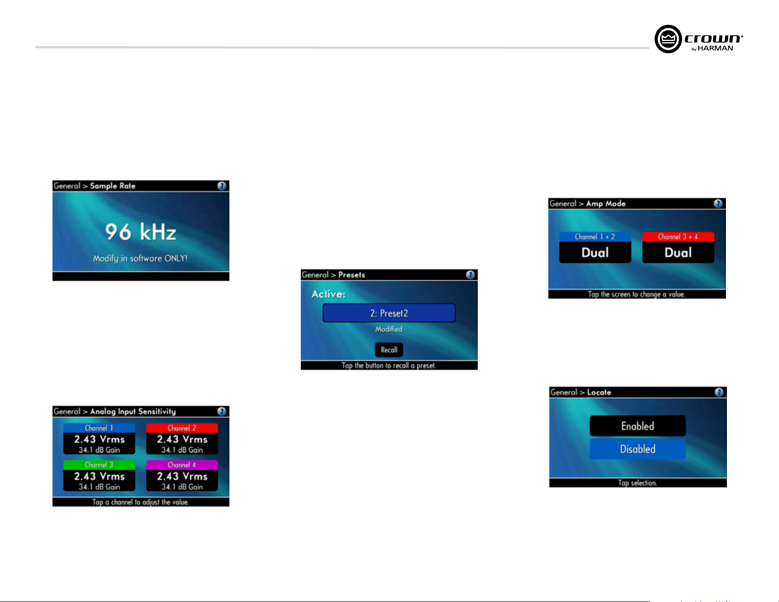
Sample Rate: Starting from the Attenuation screen, press Menu/Exit to go
to the Sample Rate screen in the advanced mode. The sample rate of the
amplifier’s DSP is displayed. It can be modified only in System Architect
software because FIR filter settings will need to be recalculated as a result of
the change. Please refer to its Help files. When you route a Cobranet input, the
sample rate displayed here must match the Cobranet source.
Analog Input Sensitivity: (Tap to select a channel, turn the encoder to adj.)
This screen also displays the amp gain for each channel resulting from the
sensitivity settings.
Note: If you do not see the sensitivity you need, try changing the Maximum
Analog Input level in the Advanced Menu (described later). This makes
different sensitivities available.
To optimize the system gain structure, see Section 3.1 in the I-Tech application
Guide at www.crownaudio.com/pdf/amps/137327.pdf.
Presets: A preset is a group of DSP and amplifier settings for a particular
speaker system. Turn an Encoder to view Presets 1 through 50. To recall a
preset, press the Encoder, then press and hold the Encoder to confirm. For
more information on presets, see Section 7.3.
The preset currently in use is displayed in the upper right corner.
(A) Active means that the amplifier is operating exactly according to that
preset.
(M) Modified means that the amplifier is operating according to the preset
but with some settings changed.
If a preset number is flashing, it is not in use.
In the example shown below,
• Preset 2 is in use.
• The amplier settings have been modied (M) since Preset 2 was loaded.
Amp Mode: This screen lets you set up the amplifier for Dual, Input Y or
Bridge Mono mode. Turn an Encoder knob to choose among those three
options, then press the knob to save your choice. You will be prompted to
confirm your choice. The LCD screen displays the currently selected mode.
• In Dual (or Stereo) mode, both channels operate independently.
• In Bridge Mono mode, pairs of channels are summed to double the power,
and the amplifier puts out a mono signal.
Locate: Allows users to identify a specific amplifier in a large network of
amplifiers without having to compare address infor mation. Locate can be
turned on/off from software and/or the front panel. Press an Encoder knob to
turn on the Locate function. When on, the LCD screen flashes. Press the knob
again to turn off the Locate function. In System Architect, the device icon has a
blue outline to indicate that it is in Locate mode.
Operation Manual
page 19
Page 20
7 Advanced Operation
I-Tech HD DriveCore Series Power Ampliers
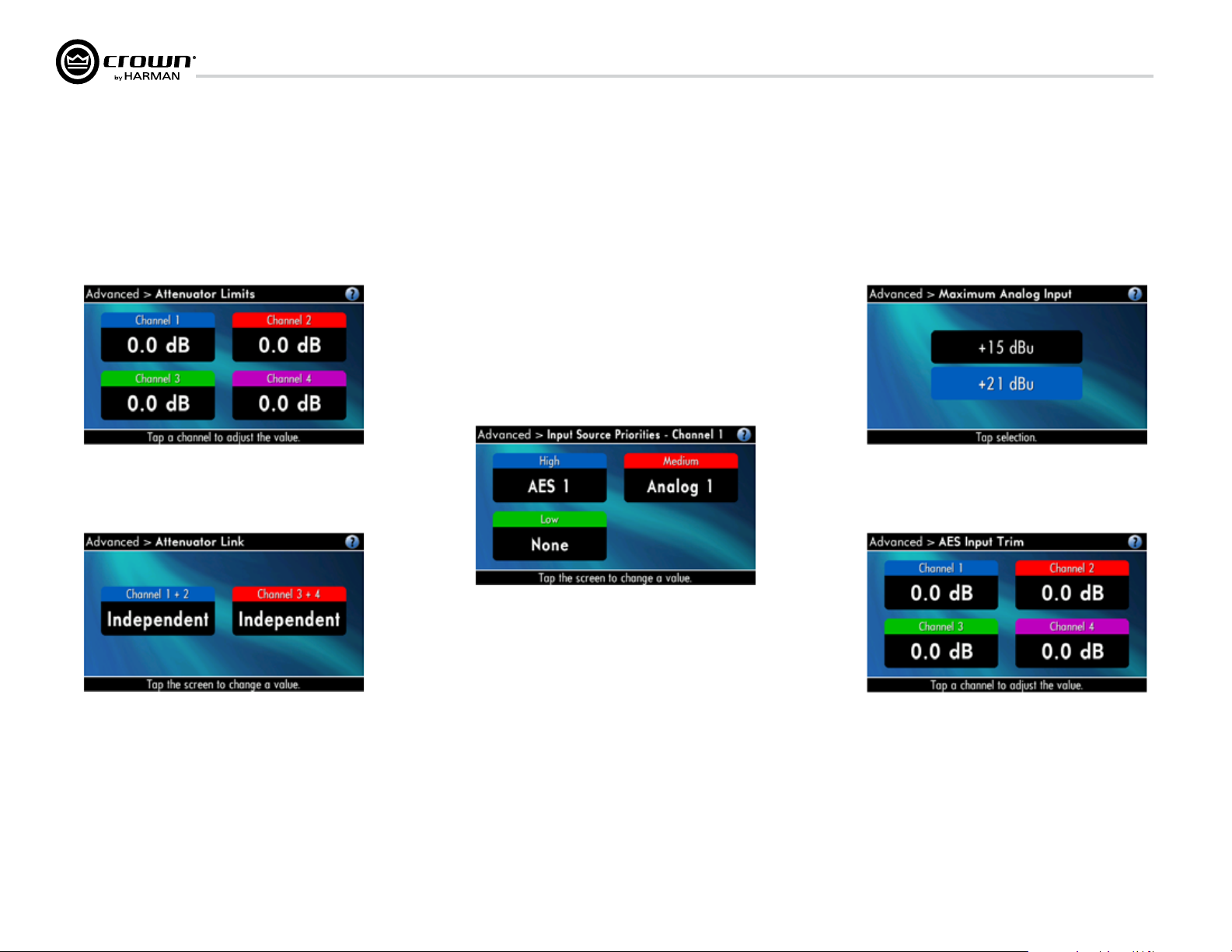
Attenuator Limits: You can set the maximum attenuation from 0 dB to
–100 dB. This feature allows you to set a limit on the attenua tors. Once set,
attenuation cannot be adjusted beyond this level.
NOTE: The attenuator setting must be below the attenuator limit that you are
trying to set. For example, if the attenuator is set at –3 dB, you cannot set the
attenuator limit below –3 dB unless you decrease the attenuator level.
Attenuator Link You can set the attenudators to be independent or linked.
Turn an Encoder knob to choose one of those options, then press the knob to
save your choice.
Input Sources: For each channel, turn the Encoder to select ana log, digital,
or CobraNet Options are:
Analog
Digital
Digital with analog backup
Digital with analog override
Digital with analog backup: The I-Tech HD is being fed a digital signal and an
analog signal. The input is currently switched to the digital signal. If it fails, the
I-Tech HD switches instantly to the analog signal.
Digital with analog override: The input is switched to the digital sig nal, and no
analog signal is applied. If an analog signal is sent, the I-Tech HD switches
instantly to the analog signal. If the analog signal fails, the I-Tech HD switches
to the digital signal after a delay set by the Hold Time slider in the Input Section
of the System Architect page.
Maximum Analog Input: Touch the screen to select: +21 dBu or +15 dBu.
Note: Changing this value changes the range of sensitivities available to the
amplifier.
For more information see Figure 7.3 and the I-Tech Sensitivity Charts in the
Appendix of the I-Tech Application Guide. It is available online at www.
crownaudio.com/pdf/amps/137327.pdf.
AES Input Trim: Turn the Encoder knob to vary the gain of the AES digital
signal for Channel 1: -100.0 dB to +20 dB. See Figure 4.4 for more
information.
page 20
Operation Manual
Page 21
I-Tech HD DriveCore Series Power Ampliers
7 Advanced Operation
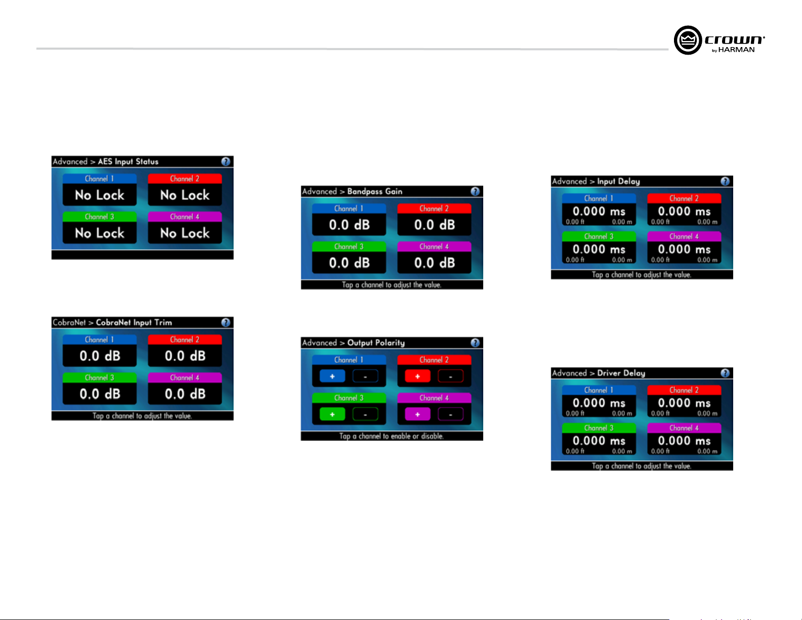
AES Input Status: “Lock” indicates that an AES cable is plugged in and the
amplifier is receiving (and locking to) the AES phase logs logs. “No Lock”
means that the amplifier is not receiving, or is not locking to the AES
clock pulse.
CobraNet Input Trim: Turn the Encoder knob to vary the gain of the
CobraNet digital signal for Channel 1: -100.0 dB to +20 dB. See Figure 4.4 for
more information.
Bandpass Gain: In each channel of the I-Tech HD’s DSP, just before the
output limiter and after the preceding filter, is a gain block (not shown on the
Signal Path block diagram). Bandpass Gain adjusts the gain of this block
between -24 dB and +24 dB.
Adjusting the bandpass gain in the LCD screen makes it easy to vary the level of
subwoofers, midrange drivers and high-frequency driv ers.
Output Polarity: Press each channel icon to toggle the output signal polarity
between + and –.
Input Delay: Sets the input signal delay in each channel. Turn the Encoder
knob to vary the delay. The delay step size is speed sensitive. Pressing the
encoder enables or disables the Delay.
Below each channel’s delay setting is the equivalent distance in feet and meters.
For example, 10 ms is the signal delay of sound traveling 11.3 feet or 3.4 m.
Output Delay: Sets the output signal delay in each channel. Turn the Encoder
knob to vary the delay. The delay step size is speed sensitive. Pressing the
encoder enables or disables the Delay.
Below each channel’s delay setting is the equivalent distance in feet and meters.
For example, 10 ms is the signal delay of sound traveling 11.3 feet or 3.4 m.
Operation Manual
page 21
Page 22
7 Advanced Operation
I-Tech HD DriveCore Series Power Ampliers
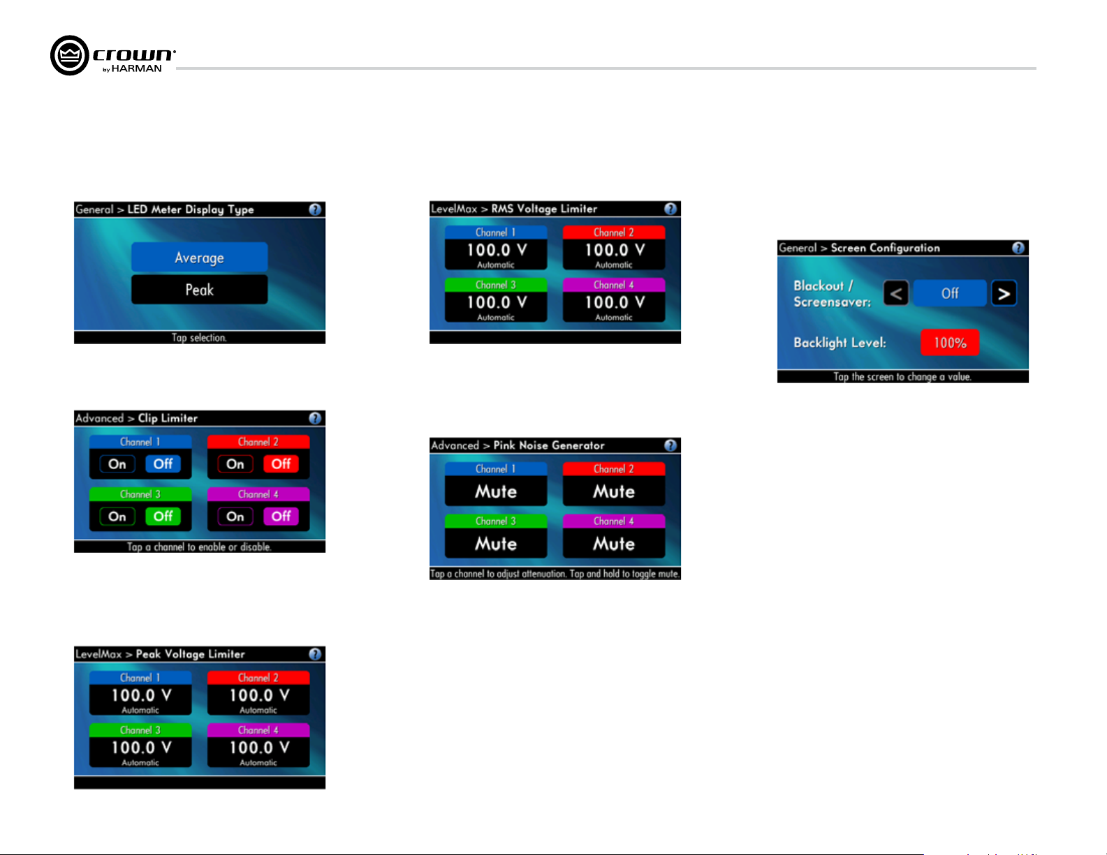
LED Meter Display Type : Here you can set the LCD bar meters to display
average or peak levels. Turn the Encoder knob to select the option, then press
the knob to confirm your selection.
LevelMax - Clip Limiter: Limits the peak output voltage to just below
clipping for each channel. Press a channel icon to turn it OFF or ON.
LevelMax - RMS Voltage Limiter: Limits the output rms voltage to an
amount that you set, either OFF or 1 to 500 volts, for each channel. Press the
Encoder to turn on the Limiter. Once it’s on, turn the Encoder to set the voltage.
Pink Noise Generator: Press a channel icon to turn on the generator. Its level
will read –100 dB. Adjust the noise level from –100 dB to +20 dB in 0.5 dB
steps by turning the Encoder. To turn off the generator, press and hold a channel
icon or go to another menu item.
Front Panel Blackout: This screen lets you black out the front panel display
unless you press a front-panel button or turn an Encoder. This feature turns
off the LCD backlight and all front panel LEDs except for the fault LEDs and
power-switch green LED. After blackout is enabled, an Encoder press/turn
will “reactivate” the display. If no button is pressed/turned for 5 seconds, the
display will return to blackout mode.
LevelMax- Peak Voltage Limiter: Limits the peak output voltage to a level
that you set, either OFF or 1 to 500 volts, for each channel. Press an Encoder to
turn on the Limiter. Once it’s on, turn the Encoder to set the voltage. Additional
controls, such as attack and release, are available through System Architect.
page 22
Operation Manual
Page 23

I-Tech HD DriveCore Series Power Ampliers
7 Advanced Operation
7.2.2 MONITOR MENU
This menu lets you monitor the status of the amplifier.
Load Monitoring: Press a channel icon to turn speaker load monitoring on
or off for a channel. When load monitoring is on, the load connected to the
amplifier output is displayed. The text below the reported load indicates
whether the value is within the limits set in Sys tem Architect. OFF means load
monitoring is off. LOW means the load is below limits. HIGH means the load is
above limits. NORMAL means the load is within limits.
(Output must be sufficient)
Thermal %: This indicates the amplifier temperature in percent, where 100%
is the maximum allowable temperature. If Thermal % reaches 100%, the
amplifier is out of thermal headroom and has shut down (or will very soon).
Measurements are shown for Channel 1, Channel 2, Channel 3, Channel 4,
and PSU.
Thermal Temp deg. C: This screen displays the temperature in degrees
Celsius of the Ch. 1 output devices, Ch. 2 output devices, Ch. 3 output
devices, Ch. 4 output, and the power supply.
AC Voltage: This shows the AC line voltage at the AC cord inlet to the
amplifier.
Watts Output: This displays the slow-averaged continuous output power of
each channel in watts.
7.2.3 ALERT MENU
This menu displays a wide variety of errors in the signal, amplifier, or load.
Amp Output Clip Errors: A clip error occurs if the number of clip events in
the amplifier output exceeds the value set with the Count slider (within the
time set by the Time slider) on the Amplifier Settings page in System Architect.
When an error occurs, the count displayed in this screen is incremented, and
the operat ing time since the error is displayed.
To clear this screen, tap a channel icon.
Operation Manual
Operating Time: This displays the number of hours the amplifier has been
on since manufacture. Like a car’s odometer, it shows the total amount of
operating hours and cannot be reset. All I-Tech HD amplifiers come with a
variable amount of operating time on them due to burn-in and testing before
shipping.
page 23
Page 24

7 Advanced Operation
I-Tech HD DriveCore Series Power Ampliers
Low Limit Load Errors: This screen lets you view low-load errors without
using the control software. A low limit load error occurs if the load
impedance falls below the value set with the Low Limit spin control on the
Amplifier Settings page in System Architect.
When an error occurs, the count displayed in this screen is incremented, and
the operating time since the error is displayed.
To clear this screen, press a channel icon.
NOTE: You must use System Architect to enable error reporting and set its
limits.
High Limit Load Errors: This screen lets you view high limit load errors
without using the control software. A high limit load error occurs if the load
impedance rises above the value set with the High Limit value on the
software Control Panel.
When an error occurs, the count displayed in this screen is incre mented, and
the operating time since the error is displayed.
To clear this screen, press a channel icon
NOTE: You must use System Architect to enable error report ing and set its
limits.
SLM (Sweep Load Monitoring) Errors: This screen lets you view SLM
errors without using the control software.
When an error occurs, the count displayed in this screen is incremented, and
the operating time since the error is displayed.
To clear this screen, press and release an Encoder. The display will prompt you
to confirm your choice by pressing and holding the Encoder.
NOTE: You must use System Architect to enable error reporting and set its
limits.
Line Voltage Errors: This screen lets you view line-voltage errors without
using the control software. A line voltage error occurs if the line voltage falls
outside the values set with the High/Low Limits slider on the Line Voltage
Page of the Control Panel.
When an error occurs, the count displayed in this screen is incre mented, and
the operating time since the error is displayed. The “Low” and “High”
indicators show whether the line voltage was below or above the line-voltage
limits.
To clear this screen, press the icon. (The display will prompt you to confirm
your choice by pressing and holding the Encoder.)
NOTE: You must use System Architect to enable error report ing and set its
limits.
Fan Errors: When a fan error occurs, the count displayed in this screen is
incre mented, and the operating time since the error is displayed.
Clear All Error Logs: In this screen, you can press and hold an the icon to
clear all the error logs.
page 24
Operation Manual
Page 25

I-Tech HD DriveCore Series Power Ampliers
7 Advanced Operation
7.2.4 NETWORKING MENU
This menu has screens for setting up audio network parameters. Push an
Encoder knob to see the selections in the Networking Menu.
Network Info: This screen displays information about the audio network: IP
address, HiQnet address, Subnet and MAC address. Section 12 of this manual
explains these terms.
Manufacturing Info: This screen displays information about your I-Tech HD
amplifier: model number, firmware version, serial number, and amplifier date
code.
HiQnet Node Address: This screen lets you set the HiQnet address of this
amplifier (a node in the network). Tap icon, then turn an Encoder knob to set
the address, then press the knob to save your setting.
DHCP: Turn an Encoder knob to turn DHCP on or off, then press the knob to
confirm your selection. With DHCP enabled, the IP address of the amplifier
might change at power-up. See System Architect Help files for more
information on DHCP.
IP Address: You set the IP address of the amplifier here. See Section 12 for
more information on IP Address. This function is disabled when DHCP is
enabled.
1. Tap the Encoder knob icon to access the left three digits, then turn the knob
to set the number.
2. Tap the Encoder again to access the middle three digits, then turn the knob to
set the number.
3. Tap the Encoder again to access the next digit to the right, then turn the knob
to set the number.
4. Tap the Encoder again to access the right-most digit, then turn the knob to
set the number.
5. Tap the Encoder again to save the IP address.
Subnet Mask: You set the Subnet Mask of the amplifier here. See Section 12
for more information on Subnet Mask. This function is disabled when DHCP is
enabled.
1. Tap the Encoder knob icon to access the left three digits, then turn the knob
to set the number.
2. Tap the Encoder again to access the middle three digits, then turn the knob to
set the number.
3. Tap the Encoder again to access the next digit to the right, then turn the knob
to set the number.
4.Tap the Encoder again to access the right-most digit, then turn the knob to set
the number.
Tap the Encoder again to save the Subnet Mask.
Operation Manual
page 25
Page 26

7 Advanced Operation
I-Tech HD DriveCore Series Power Ampliers
7.2.5 COBRANET MENU
To access the CobraNet Menu from the Attenuation screen, press the Encoder
knob, then press Prev. This menu has selections for setting CobraNet
parameters. Press an Encoder knob to access the CobraNet Menu selections.
See Section 12 and the System Architect Help files for more on CobraNet.
CobraNet Information: This screen displays information about the
CobraNet network: The firmware version, ethernet status (down or up), and
conductor priority.
Ch1 CobraNet Rx: Tap the Encoder knob to set the number of the RxA
Bundle for Channel 1. Turn the right Encoder knob to set the CobraNet input for
Channel 1. The word “Active” appears if there is audio on the bundle. Bundles
1-8 are available at 48 kHz sampling rate, and bundles 1-4 are available at 96
kHz sampling rate.
CobraNet Tx: Tap the icon then turn the Encoder knob to adj.
CobraNet Conductor Priority: Turn tap then turn the Encoder knob to set
the priority number of the CobraNet channel. Press the knob to confirm your
choice. See Section 12 for more on CobraNet conductor priority.
page 26
CobraNet Transport Latency: Tap selection to set the CobraNet transport
latency: either 5.33, 2.66, or 1.33msec. Press the knob to confirm your choice.
This latency must match the Cobranet source for proper Cobranet reception.
Operation Manual
Page 27

I-Tech HD DriveCore Series Power Ampliers
7 Advanced Operation
7.3 Presets
7.3.1 Introduction
Your I-Tech HD amplifier has a wide variety of onboard Digital Signal
Process ing (DSP). Some applications for this DSP are speaker configuration
(set ting the drive levels, frequency bands, delays and limiting for your
particular speakers), EQ, filtering, compression, and much more. System
Architect software lets you adjust the DSP settings, such as filter slope,
compression ratio, EQ frequency bands, and so on.
A preset is a group of DSP settings that configure the amp for a specific
application. For example, you might use one preset that optimizes the amp’s
DSP for a JBL VerTec Line Array. You might use another preset that sets up the
DSP for a stereo pair of loudspeakers of your choice. You can choose any of
50 presets with the LCD Control Screen.
Preset 1 is the factory default preset and cannot be overwritten. It sets up the
amplifier for stereo operation with no DSP features enabled.
The I-Tech HD amplifier works with two types of presets:
1. User presets. Using System Architect, you can create your own custom
DSP presets, label them, and send them to the I-Tech HD ampli fier. The amp
stores those presets in firmware. You can recall those presets from the LCD
Control Screen.
2. Downloadable presets. Crown and JBL engineers have designed
presets that are optimized for various JBL loudspeakers, such as VerTec Line
Arrays. You can download presets from www.jblpro.com. Then in the software,
or with a USB drive, send the preset files to the I-Tech HD amplifier, where you
can recall them from the LCD Control Screen.
We will describe each type of preset in detail.
7.3.2 User Presets
User presets are DSP presets that are configured manually.
This is the basic procedure:
1. Adjust the DSP settings as desired in the System Architect soft ware (not
with the LCD Control Screen).
2. Save this group of settings as preset. Give it a label.
3. Download the preset to the I-Tech HD amplifier. See the software Help file
for details. As soon as you save the setting as a preset, it is sent to the
amplifier. Another option, described on the next page, is to transfer the
preset file using a USB drive.
4. Select that preset from the LCD Control Screen. The preset will
automat ically set the DSP parameters as you set them up in the control
software.
Setting some parameters of the DSP in the I-Tech HD amplifier is done using
the control software, not by the amplifier’s LCD Control Screen. For example,
if you want to set filter Q, compression ratio, or graphic EQ, you would do so
within the System Architect software.
5. When you want to recall the preset, select it from the Preset screen in the
LCD display. The preset will automat ically set the DSP parameters as you set
them up in the control software.
7.3.3 Downloadable Presets
Crown and JBL engineers have designed I-Tech HD DSP presets that are
opti mized for various JBL loudspeakers, such as VerTec Line Arrays. To use
them, follow this procedure in System Architect:
Go to www.jblpro.com.
Section 7.8.19 describes the Presets Manager screen in System Architect.
7.3.4 Loading I-Tech HD 2 Channel Presets Into the
I-Tech HD 4 Channel
In System Architect, double click on HD4. Go to File › Open Preset, find a 2
Channel ITHD preset by selecting 2 Channel Preset from file “file of type” drop
down menu. Open the Preset from the and S2 will present options to load it into
Channels 1/2 or 3/4.
7.4 File Transfer Via the USB Port
On the front panel of the amplifier is a USB Type A port which can transfer files
either direction between a USB flash drive and the amplifier. These files can be
of three types:
A Preset file, which contains amplifier DSP settings for a specific
loudspeaker/amplifier configuration.
A Device file, which contain all 50 presets and the current amplifier DSP
settings.
A Firmware file.
When you plug in the drive, the amplfier defaults to a file-exchange mode (and
is muted). Then you can load or save individual files. No computer is needed
for this file transfer.
Operation Manual
page 27
Page 28

I-Tech HD DriveCore Series Power Ampliers
This message indicates that the encoder
7 Advanced Operation
7.4 List of Pop-Up Boxes and Descriptions
These messages may appear on the LCD screen.
If N/A is displayed, the particular menu has been
locked out via System Architect software.
Lockout
USB
Lockout
Invalid
Subnet
Invalid
Address
Preset
Loaded
Address
Changed
DHCP
Changed
USB Fault
Overcurrent!
Device File
is not valid!
Loading File
FAILED!
Loading File
Successful!
“Lockout” is displayed when front panel lockout has been enabled from either the
software or front panel. It prevents any changes from the display.
“USB Lockout” is displayed when USB lockout has been enabled from the software.
It disables all USB functions.
An invalid subnet mask was selected.
An invalid IP address was selected.
The selected preset has been successfully loaded.
The selected address has been modified. Applies to HiQnet node address, IP address
and subnet mask.
The current state of DHCP has been changed to either ON or OFF.
The USB drive is drawing more than 500mA of current.
The selected USB device file cannot be loaded because it is not valid. This is most
likely a device file formatting problem. Try to create a new device file.
Loading the preset or device file from the USB device failed. This could be due to the
format or contents of the file.
Loading the preset or device file from the USB device was successful.
page 28
Confirm Change
(Press knob again)
Confirm Change
(Press and Hold)
Press and Hold
(Hold knob)
Change
cancelled
No Change
Selected
Changes
Disabled
Change
Failed!
Displayed after the first button press. To continue, the user must release the button
and press it again.
Displayed after the first button press has been released. To continue, the user must
press the button again.
Displayed after the second button press. To continue, the user must continue to hold
the button for at least 2 seconds.
To modify this parameter, the encoder button must be pressed twice with the second
press being held down for at least 2 seconds.
button was not properly pressed and/or held down.
The selected object to change has not been modified from the current value.
The display does not have permission to change this parameter. The display observes HiQnet
access rights role 4. Individual screens’ parameters can be user defined as Write Protected
and/or Read Protected. When a parameter is Read Protected, a “N/A” is displayed.
The selected change was not made. It may have been out of range or invalid.
Operation Manual
Page 29

I-Tech HD DriveCore Series Power Ampliers
7 Advanced Operation
7.5 Digital Audio Options (AES3 and VDrive)
Digital audio inputs allow you to keep the amplifier input signals in the
digital domain. Keeping the input signal digital reduces the number of
Dig ital-to-Analog and Analog-to-Digital conversions. This provides
better sound quality and reduces pickup of electrical interference.
The AES3 connector provides a widely accepted format of digital audio
transmission. Con nect an AES3 signal to the AES3 connector on the
rear panel. The amplifier has a digital buffer converter so it will adapt to
any AES sample rate between 32 and 96kHz that is sent to it.
VDrive is a digital AES3 transport mechanism that combines a standard
10/100MB network connection with AES3 signals. VDrive employs the
unused pins of a 10/100MB network to transport AES3 digital audio
signals. As indicated in the chart below, one is able to transmit 4
channels of digital audio using a standard CAT5 cable.
7.6 Networking the Amplifier
If you need help understanding network concepts, please see Appendix
A on Network and CobraNet Basics. Please check the System Architect
help file for directions on how to use its networking configuration tools.
An I-Tech HD amplifier may be used in an existing I-Tech network and
can use existing I-Tech device or venue files.
VDrive Wiring Schematic
RJ45 Pin # Wire Color (T568A)
1 White/Green
2 Green
3 White/Orange
4 Blue
5 White/Blue
6 Orange
7 White/Brown
8 Brown
Wire Diagram
(T568A)
You can make the following settings via the device front panel or by
using the Network Troubleshooter (In System Architect):
HiQnet node address
DHCP off/on
IP address
Subnet mask
You cannot set the CobraNet IP address via the front panel.
7.6.1 Network Troubleshooter
The network troubleshooter can assist you in setting up your HiQnet
network for the first time. Using the troubleshooter, you can address
your components and be informed of addressing and other errors in
the system. Please note that this wizard is designed to work with
devices that are on the same physical network segment as the
computer it is running on. It will not work through a router.
Select Network Card
The first page of the wizard lists all the network adapters currently in the
computer. If you have more than one adapter, you can scroll through
the list and see the IP Address assigned to each card.
If you have a card with an IP address of 0.0.0.0, it typically means one
of several things:
1. The card is disabled.
2. The card is not connected to a network.
10Base-T Signal
100Base-TX Signal
Transmit + BI_DA+
Transmit - BI_DA-
Receive + BI_DB+
AES 1/2 + BI_DC+
AES 1/2 - BI_DC-
Receive - BI_DBAES 3/4 + BI_DD+
AES 3/4 - BI_DD-
1000Base-T Signal
3. The card is setup to obtain its address from a DHCP server, and no
DHCP server is available.
Select the card that is connected to the HiQnet system and click the
Next button. The Wizard will walk you through the rest of the process.
Please see the System Architect online help for more information.
7.7 Software-Controllable Onboard DSP
Crown’s latest-generation Digital Signal Processing is built into the
I-Tech HD amplifier. Its 24-bit/96kHz converters offer extremely low
noise and extended dynamic range. When you use an I-Tech HD amp,
the loud speaker processors, crossovers, limiters and delays are in the
onboard DSP – so you don’t need those rack-mounted devices. This
drastically cuts setup time, commissioning, rack space and costs.
The I-Tech HD’s DSP can be monitored and controlled with a computer
running System Architect software, and connected to the amplifier
Network Connector by a network Category 5 cable.
Some applications for this DSP are:
• Set up signal ow
• Optimize system gain structure
• Set up speaker congurations (set the drive levels, frequency bands,
delays and limiting for your particular speakers)
• Set up EQ, ltering, compression, and much more.
The next several pages explain some of the available DSP functions.
See the System Architect Help files for more detailed information.
The VDrive digital audio transport featured in the IT4x3500HD can be
enabled or disabled via the software or from the front display. This
selects between AES3 through the EtherCon connector utilizing VDrive.
Once AES3 has been selected either through XLR or VDrive, the preset
must be stored. This selection is preset by preset based and not a
global selection for all presets loaded in the amplifier. To select AES3
between the XLR connections or VDrive, open the IT4x3500HD device
panel, select source, then select between XLR or VDrive.
Operation Manual
page 29
Page 30

7 Advanced Operation
7.7.1 Amplifier DSP Selection Screen
On the left of this screen is the Input and Output Signal Level Monitor (explained later on this page). On the right
side are rows of DSP selection buttons for each channel. When you double click on a button, a control panel opens
for that button’s function.
Also on the right are buttons that open control panels for these functions:
• Amplier mode (dual, bridge-mono, input Y)
• Signal generator (pink noise and sine wave)
• Amplier information
• Recall and store presets
• Preset manager
• Apply to others (apply this amplier’s DSP settings to other devices)
We’ll explain each of these functions on the next several pages.
I-Tech HD DriveCore Series Power Ampliers
7.7.2 Amplifier Mode
This is accessed by double clicking the mode button.
page 30
Operation Manual
Page 31

I-Tech HD DriveCore Series Power Ampliers
7 Advanced Operation
7.7.3 Input Level, Fades, Mute, Link, I/O Level Meters, and Indicators
This panel is on the left side of the I-Tech HD’s main control panel shown above. Channels 1, 2, 3,
and 4 Level Controls set the input signal level of each channel. Each channel can be muted, and
both faders can be linked with the Link button.
Input Signal Level Meter (green)
The measure ment range is from 0dBFS to –40dBFS with 0.5dB resolution. Each audio channel
has the following monitors:
• Switched Audio Input: This meter shows only the switched (selected) audio input after the
Input Audio Router.
• Clip Indicator
Output Signal Level Meter (blue)
The mea surement range is from 0 dB to –40 dB with 0.5 dB resolution. The monitors are scaled so
that 0 dB is referenced to the full rated output voltage of the amplifier. The wider left meter is rms
and the right meter is peak for each channel. An output clip indicator is provided.
Indicators
Temp: Lights if the temperature of the amplifier is too high and the amplifier is near shutdown.
Green: Thermal headroom used up is less than 59%.
Yellow: Thermal headroom used up is 60-80%.
Red: Thermal headroom used up is more than 81%.
Limit: Lights when the amplifier signal is being limited.
Load: Lights when the load impedance is out of range.
Ready: Lights when the amplifier is on and ready to supply power.
Fault: Lights when the amplifier is in a fault mode service may be required.
Operation Manual
page 31
Page 32

7 Advanced Operation
7.7.4 Input Signal Router
Each channel of the I-Tech’s signal processing has an Input Signal Router that
lets you choose the audio signal that will be used by the channel. Choose one
of the following configurations:
• Analog Audio: This is the audio input from the audio connector on the
back panel of the amp. Choices for the Analog Audio input are Channel 1,
Channel 2, or a sum of Channels 1, 2, 3, 4, or a sum of 3 and 4.
• Digital Audio: This is the audio input from the AES/EBU connectors or
CobraNet connector on the back panel of the amp. It can be set up for Digital
with Analog Backup or Digital with Analog Override:
• Digital with Analog Backup
The input takes the digital signal as its source when the digital signal (or just
the digital clock) is present. If the digital lock is lost, the input switches to the
selected Analog Source. Once that digital lock is found again, the input
switches back to the selected digital source. This works even when the digital
signal has no audio but is sending a clock signal.
• Digital with Analog Override
The input takes the digital signal as its source. If the analog signal level is
greater than an Analog Signal Detect Threshold that the user defines, the input
switches to the analog signal. As long as the analog signal level exceeds the
threshold, or as long as its level falls below threshold for a user-defined hold
time, the input remains the analog signal.
I-Tech HD DriveCore Series Power Ampliers
Analog Signal Detect Threshold (-100 dB to 0 dB)
This option is not displayed unless override is selected. If the selected analog
signal exceeds the threshold level, the analog signal becomes the source for
this input rather than the selected digital input source. Use the numeric spin
box or the fader provided to set the threshold.
Hold Time (0 - 60 seconds)
This option is not displayed unless override is selected. Once an overriding
analog input signal falls below threshold, the Hold Time determines how long
the input will continue to be the selected analog input before reverting to the
selected digital input. Use the numeric spin box or the fader provided to set this
time.
The control operation will vary based on the mode that is selected.
page 32
Operation Manual
Page 33

I-Tech HD DriveCore Series Power Ampliers
7 Advanced Operation
7.7.5 Source Configuration
In this screen you can configure the levels and settings of the
analog, AES and CobraNet inputs. The input signal of each channel
can be independently muted.
The I-Tech HD amplifier can be set to work as a fixed gain amplifier:
any input signal is given a fixed amount of gain, either 26dB or
32dB. In addition, you can set the input sensitivity to determine how
much gain is provided. See Section 4.8.20 for more details.
Operation Manual
page 33
Page 34

4 Advanced Operation
7.7.6 CobraNet Advanced Settings
In the CobraNet Advanced Settings screen you can set the
parameters shown here. Indicators that are green can’t be
modified.
The latency on this screen is the CorbaNet transport latency or
buffering. This latency must be set to the same latency as the
source CobraNet device.
The Foldback control panel lets you select the items to
transmit via CobraNet. Selections available are the Analog
Inputs, Amplifier Outputs or AES input signal. The audio can
be routed out through only one bundle.
I-Tech HD DriveCore Series Power Ampliers
page 34
Operation Manual
Page 35

I-Tech HD DriveCore Series Power Ampliers
7 Advanced Operation
7.7.7 Input Signal Compressor
An input signal compressor is available for each channel. Several parameters control this
feature:
On/off button: Enables or disables this function.
Threshold: Sets the level, in dBu, above which the compressor begins to attenuate the input
signal. This level corresponds to the input level meter reading. The compressor is “feedforward,” meaning that the level detection point is located before the gain control stage. The
range is from +20 dBu to – 50 dBu.
Attack Time: Sets the attack time of the compressor. The attack time is defined as the time it
takes the compressor to attenuate the signal gain by 20 dB. The range is from 1 millisecond to
0.1 second.
Release Time: Sets the release time of the compressor. The release time is defined as the
time it takes the compressor to increase the sig nal gain by 20 dB. The range is from 10
milliseconds to 10 seconds.
Compression Ratio: Sets the compression ratio of the compressor. The ratio is the
relationship between the amount of attenuation applied by the compressor versus the amount
that the input signal is over the threshold. The available settings are 2:1 to 32:1.
Makeup gain: The amount of gain you want to apply to the compressed signal to raise it to a
higher level.
Knee width: The knee of the compression curve is the transition point between no
compression and compression. The wider the knee, the more gradual is the transition -- so
compression is not so obvious when the signal is close to threshold.
Beyond the controls for each channel, a single-control Com pressor Link connects the
compressors together. The compressors are tied at their sense points, meaning that the greater
of the two input signals will be used as stimulus for both compressors. Each compres sor will
still compress based on its individual threshold, attack, release and ratio settings.
Operation Manual
7.8.8 Input Delay and Driver/
Output
In these screens you can set the signal
delay for each channel in seconds, feet or
meters.
page 35
Page 36

7 Advanced Operation
I-Tech HD DriveCore Series Power Ampliers
page 36
7.7.9 Input EQ and Output EQ
These screens let you adjust channel equalization for up to 16 frequencies. You can
select filter type, frequency, gain, and bandwidth in octaves or Q as set by the user
preferences in System Architect. Changes to the equalizer’s frequency response can
be done by typing in parameters or by click-dragging the response curve.
Operation Manual
Page 37

I-Tech HD DriveCore Series Power Ampliers
7 Advanced Operation
7.7.10 Crossover Filters
The Crossover section lets you use infinite impulse response (IIR) or
finite impulse response (FIR) filters for the crossover.
FIR advantages: FIR has a longer processing latency but has less
phase artifacts compared to IIR. FIR allows for brickwall, 48dB/oct and
24dB/octave filters with zero phase shift.
IIR advantages: FIR has one processing block per channel; IIR has one
or more. For example, you can place an FIR at only one end of a channel,
but you can place an IIR at either end.
Operation Manual
The amplifier contains four FIR blocks which can be used in various
configurations:
In Duplicate mode the same settings are used on both channels, allowing
two FIR filters per bandpass. In Unique mode the FIR filters are limited to
one per bandpass. However, if the High Pass of Channel 1 and Low Pass
for Channel 2 are set to identical slopes and frequencies, you can use FIR
on all the bandpasses. The logic for this operation is built into the software
controls. In addition, the Processing (FIR) latency sets the minimum
frequency that can be set for an FIR.
A polarity inverter button lets you change the polarity of each channel
independently.
Each audio channel has three separate places where filters can be placed in the
system: input EQ (16 filters), Crossover, and Output EQ. Up to 24 filters per
channel are available, plus crossover filters and 4 filters for the signal
generator. Each filter has up to +/-24dB of gain. The following filters are
available:
• Lowpass: Bessel 2-4, Butterworth1-4, and Linkwitz-Riley 8
• Highpass: Bessel 2-4, Butterworth1-4, and Linkwitz-Riley 8
• Lowshelf: Low-frequency shelving EQ
• Highshelf: High-frequency shelving EQ
• Lowpass EQ: Variable bandwidth, can be expressed as Q (0.100 to 35) or
Octaves (0.041 to 6.672)
• Highpass EQ: Variable Q from 0.1 to 25
• Parametric EQ: Variable Q form 0.1 to 35
page 37
Page 38

7 Advanced Operation
7.7.11 LevelMax Suite
This is a suite consisting of a peak voltage limiter, average power limiter, clip limiter and thermal
transducer limiter. First you will set the mode to automatic or advanced:
• Automatic mode: The software determines the best settings based on the signal characteristics.
You can modify only the RMS threshold, Speaker Thermal threshold and time constant. Everything
else is set automatically.
• Advanced mode: You can modify the RMS threshold, Speaker Thermal threshold, time constant,
Peak threshold and Peak/RMS release.
Peak Voltage Limiter
This limits the peak voltage output ofthe amplifier.
On: Enables or disables this function. You’ll set the parameters below:
• Threshold: Sets the level, in absolute voltage, which the limiter will allow from the amplifier. The
range is from 12 V
• Attack Time: Sets the attack time of the limiter. The attack time is defined as the time it takes the
limiter to attenuate the output signal by 20 dB. The range is from 1 millisecond to 100 milliseconds.
The Instant setting attack time is instant (0 millisecond).
• Release Time: Sets the release time of the compressor. The release time is defined as the time it
takes the limiter to increase the output signal by 20 dB. The range is from 10 milliseconds to 10
seconds.
Average Power Limiter
This limits the long-term output power of the amplifier. You’ll set the parameters below:
• Threshold: Sets the average power level, in watts, which the limiter will allow from the amplifier
channel. The range is from 10 watts to 10,000 watts. This level should be set to the connected
loudspeaker’s long-term power rating. Also you must enter the loudspeaker’s nomi nal impedance.
• Attack Time: Sets the attack time of the limiter. The attack time is defined as the time it takes the
limiter to attenuate the output signal by 20 dB. The range is from 1 second to 30 seconds.
• Release Time: Sets the release time of the compressor. The release time is defined as the time it
takes the limiter to increase the output signal by 20 dB. The range is from 1 second to 30 seconds.
to 255 V
pk
pk.
I-Tech HD DriveCore Series Power Ampliers
7.8.12 Front Panel Security
Here you can choose which amplifier LCD screens to lock so they can’t be changed.
Clip Eliminator: This limiter monitors the clip events and attenuates the input signal to prevent
amplifier clipping. The attack and release times are preset to optimum rates. Only one parameter
controls this limiter. “Enable” enables or disables this limiter.
A lookahead feature prevents overshoot of the limiters. These settings were developed with JBL to
protect the speakers from overvoltage.
Transducer Thermal Limiting
This limits the long-term output power of the amplifier to what the loudspeaker load can handle
without overheating and going into thermal compression. You can set the thermal level at which the
thermal limiter engages, the thermal response time and thermal voltage. Your loudspeaker
manufacturer might be able to provide this information. Meters show the amplifier output level in
dBFS; and peak, rms, and total gain reduction.
page 38
Operation Manual
Page 39

I-Tech HD DriveCore Series Power Ampliers
7 Advanced Operation
7.7.13 Amplifier Settings
The Amplifier Output Enable button turns each channel on
or off.
Error Reporting
The I-Tech amplifier can detect four different error conditions
per channel and errors in the AC line voltage. Each error type
can be indi vidually configured to report the error through the
network. Network reported errors appear in the control software
Event Log. The following describes each error source.
Clip: A clip detector is provided each channel. These monitors
will indicate any clip condition (> 0.05% distortion) in the
amplifier channel. The clip detectors also can indicate Thermal
Level Control limiting.
The I-Tech HD can be configured to report if an excessive
number of output clip events occur in either amplifier channel.
The clip events are considered an error if they exceed the
defined count per the defined unit of time.
The Count Control sets the maximum number of events before
the error is reported. The range is 1 to 100. The Time Control
defines the amount of time that the events are counted before
starting the counting process over. Its range is 1 to 10 seconds.
Note: Clip events are defined as the start of each clip and every
10 milliseconds the amplifier is in clip thereafter. Using a high
count set ting with a short time setting may result in clip errors
never being detected.
Thermal: Errors can be generated for excessive temperature
in the output section of the amplifier channel. The Threshold
Control sets the level that, if exceeded, will generate the error
report. This control has a range of 1 to 100%.
Line voltage: The AC line voltage can be monitored and an
error generated whenever the voltage is outside of the limits set
by the soft ware.
Continuous Load Monitoring
The load supervision feature allows real-time monitoring of the
load connected to each amplifier channel. When enabled, the ITech contin uously monitors the amplifier output voltage and
current, and calcu lates the long-term average load impedance.
The measured load impedance is compared against the userdefined high and low limits. If either limit is exceeded, the
status indicator and, if enabled, the System Architect Error
Reporting functions alert the user of the problem. There are six
controls and two indicators for each channel:
On: Enables or disables the load-supervision function.
Load Status: This indicator shows the present sta tus of the
load impedance with respect to the user-defined high and low
limits.
Average Impedance: Shows the average impedance for the
connected load.
High Limit: Sets the upper bound above which the system
will report a “high” error status.
Low Limit: Sets the lower bound below which the system will
report a “low” error status.
Nominal Impedance: Sets the expected average impedance
for the connected load. This value determines the output signal
level required for the test. This parameter is also used by the
average power limiter to determine the expected power
threshold. You set this field to the nominal impedance of the
connected load per channel.
Report Errors via Network: When this is turned on, high
and low load errors are sent via the network to System Architect
software.
Fan: Using the ON button, you can enable reports of any fan
errors.
Operation Manual
page 39
Page 40

7 Advanced Operation
7.7.14 Amplifier Information
Information about the amplifier is stored in the software
system inven tory and is displayed on the software
control panels. Information includes manufacturer,
model, date code, and serial number. The green items
can’t be edited.
Channel Labels: Each amplifier includes two labels
that you may edit for your own use. Simply type in the
text areas. Use these labels to describe the channels of
your amplifier. These names will appear in the individual
processing blocks.
Attenuator Limits: This lets you set a limit on the
attenuators. You can set the maximum attenuation from 0
dB to –100 dB. Once set, attenuation cannot be adjusted
beyond this level.
NOTE: The attenuator setting must be below the
attenuator limit that you are trying to set. For example, if
the attenuator is set at –3 dB, you cannot set the
attenuator limit below –3 dB unless you decrease the
attenuator level.
Front Panel Display: This button lets you blackout the
front panel display until you press a front-panel button or
turn an Encoder. This feature turns off the LCD backlight
and all front panel LEDs except for the fault LEDs and
power-switch green LED. After blackout mode is enabled,
an Encoder press/turn will “reactivate” the display. If no
button is pressed/turned for over 5 seconds, the display
will return to blackout mode.
Front Panel Display:
I-Tech HD DriveCore Series Power Ampliers
7.8.15 Apply to Others
This screen lets you apply the System Architect settings
for your I-Tech HD amplifier to other I-Tech HD amplifiers in the venue file.
7.8.16 Delay (Latency)
Due to the nature of DSP processing, there is some inherent delay or latency within
the I-Tech HD’s DSP. These latencies are shown in Table 3 below:
page 40
Table 3 I-Tech HD latencies at two sample rates
Sample
rate
48 kHz 250µs 666µs 196µs 54µs 1.166ms
96 kHz 94µs 333µs 48µs 54µs 1.13ms
These latencies do not include CobraNet Transport Latency and FIR Processing
Latency.
ADC DSP DAC Ampli-
fier
Total
latency
Operation Manual
Page 41

I-Tech HD DriveCore Series Power Ampliers
7 Advanced Operation
7.7.17 Preset Manager
The control settings for all the functions can be stored
as presets. Up to 50 presets can be saved in the I-Tech
amp’s nonvolatile memory. Each preset can be named
with a 30 character name describing its function, which
is also stored in memory.
• The Store Preset Control saves the current setting
to the specified preset.
• The Recall Preset Control recalls the specified
preset settings. It appears in the Active Preset field. If
you change the settings after recalling a preset, the
Store button will turn yellow.
You can drag the presets to place them in a logical
order. Also, you can color-code the presets to organize
them.
Operation Manual
page 41
Page 42

7 Advanced Operation
7.7.18 Signal Generator
All channels share a noise generator that allows
noise to be mixed into the audio signal. This is useful
for noise masking applications and testing. Each
channel has the following controls:
• Noise On/Off: Turns the noise generator on or off.
• Noise Type: Selects full-spectrum white noise or
pink noise.
• Master: Sets the noise level with a fader.
The sine-wave signal generator lets you mix a
single tone into the audio signal. Its controls are listed
below:
• Sine Frequency: Sets the frequency anywhere
from 20Hz to 20kHz.
The noise generator and sine-wave generator cannot be
used at the same time.
I-Tech HD DriveCore Series Power Ampliers
page 42
Operation Manual
Page 43

I-Tech HD DriveCore Series Power Ampliers
7 Advanced Operation
Analog
input
AES
input
Cobranet
input
Maximum analog
input
Low +21 dBu (0 dB)
High +15 dBu (+6 dB)
AES input trim
Cobranet input trim
Analog
input
sensitivity
Source
select
Output
attenuator
Fixed gain
Low +21 26/32 dB
Hi +15 32/38 dB
Fixed
gain
compensation
Limiters
Amplifier
Operation Manual
Figure 7.3 The Various Gain Settings in the I-Tech HD
7.7.19 Fixed-Gain Mode in the I-Tech HD
Fixed-gain mode makes any I-Tech HD model have the same gain, regardless
of output power.
To do that, fixed-gain mode sets the Analog Input Sensitivity to 0 dB gain,
then adjusts the Fixed Gain Compensation fader, and the Maximum
Analog Input, to achieve 26 or 32 dB of gain (if the Maximum Analog Input
is set Low), or to achieve 32 or 38 dB of gain (if the Maximum Analog Input
is set High), no matter what model the amplifier is.
However, In fixed-gain mode, the input trims (Analog, AES, CobraNet) can
still be adjusted.
page 43
Page 44

8 Troubleshooting
I-Tech HD DriveCore Series Power Ampliers
“Off/Flashing/On” means that the
LED can be off, or flashing, or on.
CONDITION: Power indicator is
off and power switch is not illuminated.
POSSIBLE REASON:
• The amplier has lost AC power.
• The amplier is not plugged into the
power receptacle.
• Rear-panel breaker is off.
CONDITION: Power indicator
is off and power switch is illuminated.
POSSIBLE REASON:
• The amplier’s power switch is off.
CONDITION: Power indicator is
flashing.
POSSIBLE REASON
• The AC line voltage has dropped below
15% or has risen above 15% of the
rated range.
CONDITION: Thermal indicator is
on.
POSSIBLE REASON:
• The amplier is becoming too hot for safe
operation. Allow amplifier to cool. Check for
loads less than 2 ohms, and for excessive
input levels. Check for proper ventilation.
CONDITION: Fault indicator is
flashing.
POSSIBLE REASON:
• The amplier channel has stopped
operating. Refer the unit to an authorized
Crown Service Center.
CONDITION: Power indicator is
off and power switch is not illuminated.
POSSIBLE REASON:
• Load is wired incorrectly or Output Mode
switch in LCD-screen menu is set incorrectly. Check both.
• Input is overloaded by a signal level that
is too high. Turn down your amplifier level
controls (Encoders), or turn down the
input signal, until the clip light goes out.
Note: If the signal sounds distorted even
though the Clip LED is off, the input signal
may be distorted before it reaches the
amplifier input. Check gain staging and
output levels of the mixer or preamp.
page 44
Operation Manual
Page 45

I-Tech HD DriveCore Series Power Ampliers
8 Troubleshooting
CONDITION: No sound, even though
the amp has power. Power LED is on
with out flashing and the amp is receiving an input
sig nal. Signal indicator is on or flashing.
POSSIBLE REASON
• Speakers not connected.
• Open circuit due to speaker failure.
• There is a short on the amplier output. First
disconnect your speakers from the affected
channel(s) one by one to determine if one of
the loads is shorted.
• Ready LED is off. Channel has been set to
standby mode via the software.
• Amplier is in blackout mode. Press or
turn an Encoder to reactivate the LCD
display.
CONDITION: Data indicator not flashing, even though host computer
software is active.
POSSIBLE REASON:
• Cable between computer and amplier is bro ken
or not connected.
Note: Data indicator flashes only when the amplifier
is polled for data, or is polled to see whether it is
online.
CONDITION: Yellow LINK ACTIVITY indicator in
Ethernet connector does not illuminate or ash.
POSSIBLE REASON:
• Ethernet link is broken.
CONDITION: COND indicator is off.
POSSIBLE REASON:
• There is only one conductor allowed per network system. This
indicator is lit only when the amplifier is the conductor.
• Amplier is in blackout mode. Press or turn an Encoder to
reactivate the LCD display.
Operation Manual
CONDITION: No input signal. Signal
indicator is not flashing even though audio is
applied, and the channel is ready.
POSSIBLE REASON
• Input signal level is very low.
• Another source is selected or routed.
CONDITION: Computer does not communicate with the
network devices.
POSSIBLE REASON:
• Incorrect wiring. See Section 3.5 letter O on network wiring.
• IP Addressing is not done correctly. Use the Network Troubleshooting
Wizard in System Architect.
page 45
Page 46

9 Specifications
Minimum Guaranteed Power I-T4x3500HD
I-Tech HD DriveCore Series Power Ampliers
20 Hz - 20 kHz with 0.35% THD, all channels driven
2-ohm
2.7ohm
4-ohm
8-ohm
4-ohm Bridge
8-ohm Bridge
70Vrms Direct
100Vrms Direct
Performance I-T4x3500HD
Input Sensitivity (volts RMS) for rated output Adjustable in 0.1V steps from
Voltage Gain for full rated power at 8 ohms 37.1 dB to 22.2 dB
Frequency Response (20Hz to 20kHz at 1 watt, 20Hz - 20 kHz) ± 0.25 dB
Signal to Noise Ratio below rated full-bandwidth power, A-weighted > -108 dB
Total Harmonic Distortion (THD) at full rated power at 1 kHz < 0.35%
Intermodulation Distortion (IMD) 60 Hz and 7 kHz at 4:1,
from full rated output to –35 dB
Maximum Input Level +15 dBu or +21 dBu, depending on setting of
Latency 1.16 mS at 48 kHz, 1.13 mS at 96 kHz
20 Hz - 20 kHz
2,100W
2,200W
2,400W
1,900W
4,200W
4,800W
2,100W
2,300W
maximum input level
1 kHz 20ms Burst
1.28V to 8V
< 0.06%
3,500W
3,800W
4,000W
1,900W
7,000W
6,000W
A/D, D/A Converters 24-bit 96 kHz Cirrus Logic
Digital Input AES/EBU, 24-bit, 32-96 kHz.
Onboard sample rate converter.
Network Onboard HiQnet and TCP/IQ, compatible with
standard 100Mb Ethernet hardware
DSP 24-bit conversion with 32-bit, floating-point DSP
processing
Attenuators Speed-sensitive rotary encoder, 0.5 dB steps,
range 0 to –100 dB.
page 46
Operation Manual
Page 47

I-Tech HD DriveCore Series Power Ampliers
9 Specifications
Performance I-T4x3500HD
Damping Factor (8 ohms): 20 Hz to 100 Hz > 5000
Crosstalk (below rated power, 20 Hz to 1 kHz) > 80 dB
Common Mode Rejection (CMR) (20 Hz to 1 kHz) > 55 dB, typically > 70 dB
DC Output Offset (Shorted input) < ± 3 mV
Input Impedance (nominal) 20 kilohms balanced, 10 kilohms unbalanced
Load Impedance (Note: Safe with all types of loads)
Stereo
Bridge Mono
Required AC Mains Universal AC input, 100-240VAC +-10%,
AC Line Connector USA, UK, European, Australia, India, Brazil, China
Construction I-T4x3500HD
Ventilation Flow-through ventilation from front to back
Cooling Dual-zone, microprocessor controlled,
Dimensions EIA Standard 19-inch rack mount width (EIA
Weight
Net
Shipping
2-4-8-16 ohms, 70V/100V
2-4-8 ohms, 70V//100V
50/60 Hz. Max. AC mains voltage.
(USA ships with Hubbell L6-30)
continuously variable speed fans
RS-310B), 3.5-inch (8.9-cm) height, 16.95-inch
(43.1-cm) depth behind front mounting surface
29 pounds (13.1 kg)
37 pounds (16.8 kg)
Operation Manual
page 47
Page 48

9 Specifications
Charts
I-Tech HD DriveCore Series Power Ampliers
page 48
Figure 9.1 Typical Frequency Response (1W)
Figure 9.2 Typical Crosstalk vs. Frequency
Operation Manual
Page 49

I-Tech HD DriveCore Series Power Ampliers
9 Specifications
Operation Manual
Figure 9.3 Typical Damping Factor vs. Frequency
page 49
Page 50

10 AC Power Draw and Thermal Dissipation
I-Tech 4x3500HD AC Current Draw and Thermal Dissipation:
I-Tech 4x3500HD AC Current Draw and Thermal Dissipation:
Pink noise 12dB crest factor, bandwidth limited 22Hz to 22kHz.
Typical line impedance used.
Data based on all channels driven.
Pink noise 12dB crest factor, bandwidth limited 22Hz to 22kHz.
Typical line impedance used.
Data based on all channels driven.
LoadCondition
Line Current
Amps
I-T4x3500HD
120 VAC / 60 Hz
Power Dissipated as Heat
Watts BTU
kcal/hr
Line Current
Amps
I-Tech HD DriveCore Series Power Ampliers
208 VAC / 60 Hz 240 VAC / 60 Hz
Power Dissipated as Heat
Watts BTU
kcal/hr
Line Current
Amps
Power Dissipated as Heat
Watts BTU
kcal/hr
Idle (sleep mode)
Idle (awake)
1/8th Power Pink Noise 8 Ohms/Ch.
Typical of program material
just at clip.
1/3rd Power Pink Noise 8 Ohms/Ch.
Typical of program material
at extreme clip.
4 Ohms/Ch.
2 Ohms/Ch.
4 Ohms/Ch.
2 Ohms/Ch.
1.0
2.1
13.5
16.0
17.0
32.2
33.0
36.8
75
335
559
787
886
962
1084
1521
page 50
256
1143
1907
2686
3023
3285
3699
5191
65
288
481
677
762
828
933
1309
1.3
2.1
7.9
8.8
9.1
17.5
19.1
19.9
88
328
591
625
777
1180
1092
1228
300
1119
2017
2133
2652
4027
3729
4191
76
282
509
538
669
1015
940
1057
1.4
2.1
7.6
7.2
8.8
16.5
17.5
19.6
100
335
620
766
979
1027
1092
1506
341
1143
2115
2615
3343
3506
3729
5140
Operation Manual
86
288
533
659
843
884
940
1296
Page 51

I-Tech HD DriveCore Series Power Ampliers
11 Advanced Features
11.1 Protection Systems
Your Crown amplifier provides extensive
pro tection and diagnostic capabilities, including
thermal level control, fault indicators, high-pass
filtering, DC protect, AC under/over volt age
protection, inrush limiting, and variable-speed
fans with tachometer feedback. Microprocessor
monitors fans, and signals an error via System
Architect if fans are not operating.
11.1.1 Thermal Level Control (TLC)
If the amplifier becomes too hot for safe
opera tion, the TLC will engage the input
compressor and the clip LED will illuminate. By
compress ing the input, the amplifier will not
generate as much heat and will have a chance to
cool down. The degree of compression is
proportional to the amount of overheating. This
feature allows the show to go on, rather than
having the amplifier shut down, and only occurs
in extreme situations.
11.1.2 Circuit Breaker
If the current draw of the amplifier exceeds safe
limits, this breaker automatically disconnects the
power supply from the AC mains.
11.2 Global Switching Power
Sup ply with PFC
Thanks to its global power supply, the I-Tech
amplifier works anywhere in the world. There’s
no need to reset an AC mains voltage switch,
and no need to order a special model. The amp
will work and meet all specs on 100V - 240VAC,
50/60 Hz.
Crown’s Switching Power Supply minimizes the
amplifier’s weight.
Typical non-switching power supplies require
large, heavy transformers in order to produce
the required power at the output stage. These
transformers must be large to operate at 50 to
60 Hz (standard AC supplied by the power
company).
By contrast, switching power supplies can operate with a much smaller (and lighter)
trans former because they first convert the AC up
to a much higher frequency, thereby reducing
waste.
Power Factor Correction (PFC) controls how
your amplifier draws current from the AC mains.
Instead of drawing high-magnitude cur rent
spikes that reduce the capacity of your power
distro (and couple noise into other sys tem
components), PFC draws a smooth and quiet
current waveform that is in phase with the mains
voltage waveform. PFC allows you to reduce the
size and weight of your power distri bution and
improve the performance of your signal
processors.
11.3 6th Generation Class I
Cir cuitry
Class I (BCA, Balanced Current Amplifier)
Interleave technology allows high levels of
power output without all the associated heat
found in a conventional amplifier. This highly
efficient design also provides accurate,
uncol ored sound with very low distortion and a
high damping factor for tight, clean bass
response. And it can deliver more power to
reactive loads than conventional dissipative
designs (com fortably driving the latest hightechnology transducers). Class I also reduces
current draw of the AC mains, providing energy
conserva tion.
11.4 Color-Coded Rear Overlay
The labels on the rear panel are color coded to
group similar functions under common colors.
Operation Manual
page 51
Page 52

12 Appendix A: Network and CobraNet Basics
I-T4x3500HD
12.1 HiQnet Networks
Background: A Local Area Network (LAN) is a group of computers in a venue that
share data, either through cables or via wireless transmission. Ethernet is a popular
LAN communication protocol for PCs. An audio network is a Local Area Network
made of audio devices and one or more computers. A subnet is a small network within a
larger network. For example, an audio network might have two subnets: one for
enter tainment audio, and one for paging.
One use of an audio network is to control and monitor power amplifiers on stage from a
computer at Front-of-House. You can set amplifier levels, adjust crossovers, measure
speaker impedance, check for overheating and clipping, all from the house mixing
con sole.
You need a way to send computer commands to several audio devices at once. This is
done with an Ethernet switch, which is something like an audio Y cable or distribu tion
amp. The computer, and all the audio devices, connect to the switch as in Figure 12.1.
HiQnet protocol lets you control and monitor cer tain Harman products (including
Crown) on an Ethernet network. Figure12.1 shows a typical HiQnet network.
HiQnet control offers many advantages:
I-Tech HD DriveCore Series Power Ampliers
I-T4x3500HD
I-T4x3500HD
Computer
I-T4x3500HD
• Use of “off-the-shelf” network hardware. HiQnet uses standard hardware
commonly used in the computer industry, making it both low-cost and readily available.
• Better Performance. Meters display faster in realtime because the network is wide
bandwidth.
HiQnet provides these functions:
• Quickly find all HiQnet components connected to the network.
• Synchronize multiple control points on a network.
• Control and monitor components on different Local Area Networks (LANs) through the
use of an IP router (explained later).
• Upgrade firmware via the network.
Network Addresses
Each component in a HiQnet network has three addresses to identify it:
• Media Access Control (MAC) Address
• Internet Protocol (IP) Address
• HiQnet Address
Let’s explain each identifier.
page 52
I-T4x3500HD
Laptop
100Mb Switch
Figure 12.1 A HiQnet Network
Operation Manual
Page 53

I-Tech HD DriveCore Series Power Ampliers
MAC address: Short for Media Access Control, MAC is an address for an audio compo nent
that is burned into firmware in the component by its manufacturer, and cannot be changed.
Every component in a network has its own unique MAC address. The MAC address is printed
on a label outside the component. It is shown in hexadecimal format as 6 two-byte octets such
as:
00-0A-40-00-DC-2F
HiQnet Address: When you set up a network with System Architect soft ware, you assign an
address to each component. Each component has its own address, numbered from 1 to
64,999.
AUDIO NETWORK VENUE NETWORK
Internet Protocol (IP) Address: When you set up a network, you assign an IP address to
each component. The IP address identifies each component. That way, certain data can be
sent to the correct address (the correct component). An IP address has four numbers
sepa rated by periods. Each of the four numbers must be 0 to 255. For example:
192.168.0.1
Part of an IP address the network ID, and the remaining part is the host ID. The host ID is
either:
• A subnet number and a device address.
• A device address (if there is no subnet in the network).
To identify which part of the IP address is the network ID, you assign a Subnet Mask to the
network. A Subnet Mask is four numbers (0-255) separated by periods. “255” means “this
part of the address is the network ID”. For example, if the subnet mask is 255.255.0.0, and the
IP address is 192.168.0.127, the network ID is 192.168.
IP Router
To communicate between different networks, you need an IP Router. Any control data or
monitor data that is sent to the other network must go through the IP Router.
The IP address allows components and computers on multiple networks to communicate with
each other through the use of an IP Router as shown in Figure 12.2.
Here is an application for a router. Wireless devices, because of bandwidth limitations, can not
be on a CobraNet network. However, the wireless devices can be on a non-CobraNet net work,
and access CobraNet devices through a router using IP addressing.
Discovery is the process where System Architect finds all the devices on an audio network
and lists them on the computer screen. Discovery cannot be done through an IP router, so a
Discovery Proxy is required. If you need to control or monitor components that are on
another subnet, you will need to specify ONE component on the remote network that can act
as a Discovery Proxy. Currently, all networked Crown products except the PIP Lite can
function in this capacity.
PIP-Lite
I-Tech HD power amplifiers
Laptop
Computer
Computer
Laptop
100Mb Switch
Figure 12.2 Multiple-Network Communication Via an IP Router
IP Router
Wireless Access Point
100Mb Switch
To add a Proxy, select Setup > Network Setup > Proxy addresses. Choose any one of the
components listed above, type its IP address in the box under Proxy Addresses, then click the
Add button. To remove a Proxy, select the IP address in the list and click the Remove but ton.
Operation Manual
page 53
Page 54

12.2 A Closer Look at CobraNet
Licensed by Cirrus, CobraNet is a protocol, firmware and hardware that lets you transmit digital audio over a 100Base-T Fast-Ethernet network.
This section provides an overview of CobraNet. Cirrus Logic has provided a number of
technical papers that describe CobraNet in detail. These papers are available at:
http://www.cobranetinfo.com.
12.2.1 Fast Ethernet
(100Base-T)
Fast Ethernet (100Base-T) runs at 100Mbps (Megabits per second). It uses a hub or
network switch to interconnect all network nodes (components). This forms a star
network (see Figure 9.1). In a star network, all PCs are connected to a centralized hub
or switch. Messages are sent from the originating PC to the hub, which then transmits
the message either to the whole network or, if a switched hub (network switch) is used,
to the destination device only.
In larger Fast Ethernet networks, additional hubs, concentrators, and other network
hardware are used to form a larger network, as shown in Figure 12.4.
Today, commonly available networking cards are 10/100Base-T capable, which allows
them to be used on either 10BaseT or 100Base-T networks.
The maximum length of cable for CobraNet is the same as for Ethernet:100 meters over
CAT-5 copper cable, 2 kilometers over multimode fiber. Proprietary “Fast Ethernet via
single mode fiber” networks can reach even further.
I-Tech HD DriveCore Series Power Ampliers
Figure 12.3 Star Topology
12.2.2 Audio Specs
Sample rate: CobraNet can handle sample rates of 48 kHz or 96 kHz. I-Tech HD is
switchable between 48 kHz and 96 kHz.
Bit depth: Set each channel to transmit 16-, 20- or 24-bit audio data as desired.
Latency: The transmitter and receiver buffers required for reliable transmission are
set to 256 samples as a default. This gives a network transmission latency of 5.333 mS
(256 samples at 1/48 kHz per sample). I-Tech HD latency is switchable between 1.33,
2.66, and 5.33 mS.
12.2.3 Bundles and Audio Channels
You assign all audio channels to groups called Bundles for transmission over the
CobraNet network. Bundles were formerly called Network Channels.
A bundle can carry up to 8 audio channels. Up to 8 bundles can be sent in a 100 Mbps
line, depending on the signal’s bit depth and sampling rate. Only 4 bundles are available when 96 kHz sampling rate is in use.
The usual assignment is 8 channels at 20 bits. You can use fewer channels per bundle,
but maximum size bundles are suggested for the most efficient use of network bandwidth. If 24-bit data is desired, then only 7 audio channels can be loaded into a single
Bundle. With a 96 kHz sample rate, only 4 channels of audio are available.
page 54
Figure 12.4 Multi-Star Topology
Operation Manual
Page 55

I-Tech HD DriveCore Series Power Ampliers
In System Architect, you create audio connections between sending
devices (transmitters) and receiving devices (receivers). For example,
a mixer could be a transmitter, and a power amp could be a receiver.
You assign each connection a Bundle number. The Bundle number
indi cates which devices are communicating with each other.
Also in System Architect, you address each connection as Multi-
cast or Unicast. A Multicast (Broadcast) connection is from one
trans mitter to multiple receivers. A Unicast connection is from one
transmitter to one receiver. For example, if you send a mixer’s digital
audio signal to sev eral power amps, the signal would be Multicast.
Unicast is most used on “switched” networks requiring more than 64
channels.
You specify a connection as Multicast or Unicast by the delivery
address it you give it in System Architect. 255 and lower is Multicast
(Broadcast); 256 and up is Unicast.
The “Receiver Count” monitor indicates how many devices are
receiving the digital audio bundle. The “Active” indicator indicates
whether the par ticular Bundle is being actively transmitted onto the
network.
12.2.4 The Conductor
A CobraNet system is coordinated by one audio device in the network
called the Conductor. It regulates the CobraNet digital audio traffic
on the CobraNet network. That is, the Conductor is the master clock
for the rest of the network.
You choose one device to be the network conductor based on a
priority scheme. The Conductor indicator will light on the CobraNet
device that is serving as the conductor.
The Conductor handles time-division multiplexing and clock recovery
on the network. The Conductor periodically broadcasts a well-defined
“beat” packet to all components to recover synchronous timing
information. The “beat” also specifies which addresses can transmit
at certain time slots within the “beat” period.
Each transmitting device is allowed to transmit in a given time-slot
within the Conductor-controlled isochronous cycle time. The timeslot is deter mined by the assigned bundle priority. Higher bundle
priorities receive lower-numbered positions and are transmitted first.
12.2.5 Switched Networks
A more complex CobraNet network can be built using Ethernet
switches. Switches do not simply broadcast each and every packet
to all nodes. Instead, they check each incoming data packet to
determine its destination and (very quickly) transmit the data to only
that destination port. This allows for more network data flow, more
Bundles and more audio channels.
In effect, each network port in an audio component has 100MB of
band width. The network can be as large as 100MB times the number
of ports on the network.
Another advantage of switched networks is “full-duplex” connections
between components. A full-duplex link allows simultaneous send
and receive over the same Ethernet connection.
Operation Manual
page 55
Page 56

13 LevelMAXTM Limiter Suite
The I-Tech HD LevelMAX™ Limiter Suite features three types of limiting:
• Peak
• RMS
• Transducer Thermal
and three modes of operation:
• Auto
• Advanced
• Manual (OEM Factory Locked)
The standard i-Tech HD LevelMAX limiter panel (Advanced Mode) is shown
below:
I-Tech HD DriveCore Series Power Ampliers
LevelMAX has been designed to limit accurately to the specified voltage
thresholds. The addition of a thermal limiter allows thresholds for the
faster-acting RMS and peak limiters to be set higher, providing more output
and maintaining dynamic range before the onset of limiting, while protecting
the long term integrity of the transducers.
In Auto or Advanced modes, turning on the LevelMAX Limiter Suite will
enable all three limiters: Peak, RMS and Thermal.
The three LevelMAX limiter types and operating modes are outlined in the
following sections.
page 56
Operation Manual
Page 57

I-Tech HD DriveCore Series Power Ampliers
14 LevelMAX Limiters
14.1 LevelMAX Peak Limiter
LevelMAX Peak limiting instantaneously limits the output voltage to
not exceed the defined peak threshold voltage.
14.2 Peak Limiter Threshold (Vpk)
In Auto mode, the peak limiter threshold value is automatically
determined from the defined RMS threshold and the low pass
frequency defined in the XOVER block. For a low pass frequency less
than 100 Hz, the RMS to peak threshold ratio is 6 dB. From 100 Hz to
400 Hz, the RMS to peak ratio increases from 6 dB to 9 dB. Above 400
Hz, the ratio remains at 9 dB.
For Advanced and Manual modes, the peak limiter threshold can be set
by the user.
14.3 Peak Limiter Attack (sec)
The peak limiter attack time is instantaneous and cannot be modified.
The output voltage is limited to the value defined by the peak limiter
threshold (see 14.1).
14.4 Peak Limiter Release (sec)
In Auto mode, the peak limiter release time is determined by the high
pass frequency defined in the XOVER block.
For Advanced and Manual modes, the peak limiter release time can be
set by the user.
14.5 Peak Limiter Look-Ahead
Peak Limiter Look-Ahead inserts a delay into the peak limiter signal
path in order to ‘look’ at the input signal and anticipate when the peak
threshold will be exceeded. If it detects that the threshold will be
exceeded, the signal is gradually reduced prior to reaching the
threshold, while still limiting to the correct peak voltage. This approach
eliminates a sharp signal discontinuity which, in turn, could create
audible distortion.
The peak limiter look-ahead value is 0.5 ms. This value was determined
to be subjectively acceptable for most frequency ranges while not
adversely compromising overall latency. Overall latency remains
constant regardless of whether the LevelMAX Limiter suite is enabled
(ON) or bypassed (OFF).
14.6 LevelMAX RMS Limiter
LevelMAX RMS limiting accurately limits the output signal to the
specified RMS threshold voltage.
14.7 RMS Threshold (VRMS)
The RMS Threshold should be set by the user to correspond to the
short term (2 hour) power handling of the transducer or system.
Refer to the appropriate JBL Specification Sheet, Technical Manual or
Product Manual for two hour power ratings. To calculate the RMS
Threshold in VRMS, use the following equation:
where AES Power (Wrms, 2 hour) is the free air component power
rating.
If minimum impedance data is unavailable, use nominal impedance. If
2 hour AES power ratings are unavailable, use 2 hour IEC power
ratings. For most applications, it is recommended to operate LevelMAX
limiters in Auto mode so that peak thresholds are automatically
calculated based on the RMS threshold and selected LP frequency
(see 14.1).
=
14.8 LevelMAX Transducer Thermal Limiter
LevelMAX Transducer Thermal limiting is designed to protect
transducers from long term thermal damage by gradually adjusting the
RMS threshold until the target long term thermal threshold voltage has
been reached. The thermal limiter functions only when the RMS limiter
is enabled and when the thermal voltage threshold is lower than the
RMS threshold. On the main limiter panel, the thermal protection LED
turns on once the thermal limiter is 0.75 dB into limit.
14.9 Thermal Voltage (V
The thermal voltage threshold should be set to correspond to the long
term (100 hour) power handling of the transducer or system.
Refer to the appropriate JBL Specification Sheet, Technical Manual or
Product Manual for 100 hour power ratings. To calculate the Thermal
)(Impedance Minimum)hour2,(PowerAES)(ThresholdRMS ohmsxWrmsVrms �
Voltage Threshold in VRMS, use the following equation:
=
where Power (Wrms, 100 hour) is the 100 hour power rating.
If 100 hour power handling data is unavailable, set 100 hour power
rating ≈ 0.8 x 2 hour power rating.
14.10 Thermal Response Time (s)
The thermal response time is the amount of time the average RMS
signal is above the thermal threshold voltage before limiting begins.
Once the threshold has been exceeded for the amount of time defined
by the thermal response time, the RMS threshold is lowered until the
target thermal voltage has been reached. The thermal response time is
not the time it takes to reach the target voltage, although the longer the
thermal response time, the longer it takes to reach the target voltage. It
is also dependent on the amount of gain reduction and the ratio
between RMS and thermal thresholds.
Thermal response time is transducer-dependent and should be based
on the initial temperature rise of the transducer voice coil to protect it
from thermal overload.
If detailed transducer data is unavailable, the Thermal Response Time
should be left at the default value of 10 sec.
RMS
)
)(Impedance Nominal)hour100,(Power)(ThresholdThermal ohmsxWrmsVrms �
Operation Manual
page 57
Page 58

I-Tech HD DriveCore Series Power Ampliers
15 Appendix B: Table of Parameters Modified by Each Mode with LevelMAX Limiter Suite Enabled
Parameter Auto Advanced Visible in Main Panel
Peak Enable
Peak Threshold
Peak Attack
Peak Release
RMS Enable
RMS Threshold
RMS Attack
RMS Release
RMS Detector Time
Thermal Enable
Thermal Threshold
Thermal Attack
Thermal Slope (Kp & Ki)
Look-Ahead
page 58
Operation Manual
Page 59

I-Tech HD DriveCore Series Power Ampliers
SV Value Range Auto Peak max for each model (online)
Parameter Auto Increment
Peak Threshold
(See Below)
Peak Release 0.1ms-10s 1ms
RMS Threshold 1-200V 1V
RMS Attack 0-10s n/a
RMS Release 0-10s 1ms
RMS Detector Time 1ms-1s n/a
Thermal Threshold 1-200V 0.1V
Thermal Attack 1-600V 1s
Thermal Slope (Kp & Ki) 1-10 n/a
1-400V 1V
Parameter Auto
I-Tech HD 5000 201.2
I-Tech HD 9000 217.6
I-Tech HD 12000 233.4
I-Tech 4x3500 HD 217.6
Look-Ahead 0-10ms n/a
Operation Manual
page 59
Page 60

16 Application of FIR Filters to Loudspeaker Crossovers
DELAY DELAY DELAY DELAY DELAY DELAY
IN
SUM
OUT
I-Tech HD DriveCore Series Power Ampliers
16.1 FIR Overview
The powerful DSP processing in the latest Crown I-Tech HD Series
amplifiers allow sophisticated Finite Impulse Response filters as well.
FIR filters offer a number of very strong advantages when used to
implement DSP electronic loudspeaker crossovers.
Although high-order IIR filters, which are based on conventional
analog filters, can be designed to provide high stop-band roll-off rates,
the resultant filter phase response is highly nonlinear. This
significantly complicates crossover design and implementation.
As compared to IIR filters, FIR filters can be straightforwardly designed
to allow extremely narrow crossover overlap between adjacent drivers
with high stop-band attenuation and very-high rolloff rates. In-phase
and linear-phase crossovers can easily be designed. Minimizing
overlap dramatically reduces polar lobing and vastly improves off-axis
response through the crossover region.
This white paper briefly describes the characteristics and pros/cons of
FIR and IIR filters, discusses the desirable attributes of FIR filters, and
closes with a set of example measurements on a two-way loudspeaker
system to illustrate the practical application of IIR and FIR crossover
filters. In addition, audio demonstration files are available on Crown’s
web site that demonstrates the effects described in this white paper
(see comments at the end of this report).
16.2 What are IIR Filters and FIR Filters?
A filter modifies certain characteristics of a signal such as amplitude/
phase frequency response and wave-shape in a desired manner. This
can be done either in a purely analog manner with a real piece of
hardware such a non-computer based equalizer or filter set, or with a
computer-based instrument running mathematical algorithms using
digital signal processing techniques. These algorithms can be either
implemented in hardware and/or software. The term “digital filter”
refers to the specific hardware or software routine that performs the
filtering algorithm.
Digital filters may be further classified into two general types: Infinite
Impulse Response (IIR) and Finite Impulse Response (FIR). Fundamentally, IIR filters include feedback (recursion) in their implementation
while FIR filters do not. The feedback in an IIR filter means that the
impulse response of the filter theoretically goes on forever, thus the
“Infinite” term in the name. The impulse response of a FIR filter, on the
other hand, is finite because there is no feedback. Simplified structures
for both these types of filters are shown in Fig. 16.1.
IN
SUM
IN
DELAY DELAY DELAY DELAY DELAY DELAY
SUM
OUT
DELAY
DELAY
DELAY
OUT
Fig. 16.1 Simplified filter structures of an IIR (top) and FIR
(bottom) filter
The IIR structure on the left feeds back weighted the delayed versions of
the output signal back to the input and thus sets up a form of
recirculation which effectively goes on for forever once a signal is
applied to the input. The FIR structure on the right feeds weighted and
delayed signals to the output ounly and thus can’t recirculate the
signals. Effectively there is only a single path through the FIR filter.
16.3 Pros and Cons of IIR and FIR Filters
The following table lists several characteristics of the two types of
filters and their pros and cons.
Characteristic IIR Filter FIR Filter
Linear Phase
Response
High Rolloff Rates
Implement
Complex Filters
Not Possible Possible
Yes, but with
phase distortion
Yes, without
phase distortion
No Yes
Stability Conditionally Naturally Stable
Computational
Complexity
Implementation
Few CPU cycles
Common
Practice
Massive CPU
cycles
Difficult to
achieve with
limited DSP
16.4 Desirable Attributes of FIR Filters
Linear Phase
FIR filters can be designed to have exact linear phase. Linear-phase
filters provide minimal modification to the wave shape of a signal and
also greatly simplify crossover design and implementation because the
filter does not change the phase of the drivers being crossed over.
A linear phase crossover does not mean that the overall response of the
crossover including driver response is linear phase. This can be true
only if the individual drivers themselves are linear phase or can be
equalized to be linear phase.
Electronic crossovers using conventional non-linear phase filters such
as IIR filters can artificially increase the crest factor of a signal and thus
decrease the headroom in the transmission channel.
page 60
Operation Manual
Page 61

I-Tech HD DriveCore Series Power Ampliers
16 Application of FIR Filters to Loudspeaker Crossovers
16.5 High Rolloff and Steep Slopes
FIR filters can be designed to have extremely high stop-band rolloffs
and exceptionally steep slopes which greatly minimizes crossover
driver overlap. In a conventional analog or analog-based IIR crossover,
driver overlap can extend over two or three octaves. FIR crossovers
dramatically restrict the operating overlap bandwidth of the crossover
which considerable reducers the range over which both upper and
lower range drivers are radiating in the same frequency range. Very
narrow overlaps of one-third octave or less can be implemented with
FIR filters.
In addition, the extremely steep slopes of FIR filters offer greater driver
protection and reduced distortion. Beyond the driver’s linear frequency
range, energy is attenuated so rapidly that most non-linearity’s cease to
be a problem. The driver does not need to be as well behaved outsied
its frequency range. Power handling capability of HF drivers is much
improved. The narrower crossover region also lessens the need for
precise driver time alignment since the overlap region is so small.
16.6 Stop-band Attenuation
Associated with the very high stop-band rolloff of an FIR filter, is the
associated extremely high stop-band attenuation. This minimizes
interaction between adjacent drivers such as a low-frequency woofer
signal bleeding into a tweeter and thus causing intermodulation
distortion. In a home theater setup, high stop-band attenuation of the
subwoofer minimizes subjective localization of the woofers due to
hight-frequency bleed through.
16.7 Polar Lobing Error
Polar lobing is a potential problem when spatially separated
non-coincident drivers are crossed over. Throug the crossover region
both drivers are radiating simultaneously. This may cause a narrowing
of the coverage pattern and the creation of a directional lobe. It is very
desirable that this lobe face straight ahead, and not directionally
wander with frequency. If it does, lobing error occurs.
Polar lobing error is minimized when the low- and high-pass sections
of the crossover are in-phase with each other throughout the crossover
are in-phase with each other throughout the crossover region. This is
an attribute of the “Linquitz-Riley” (LR) type of crossover rewponses.
Polar lobing can also be minimized by reducing the crossover overlap
with zero-phase sharp-cutoff filters such as provided by FIR filters.
16.8 Crown’s Implementation of FIR Filters
Crown’s FIR filter implementation uses state-of-the-art digital signal
processing techniques which are highly optimized for the DSP engine
in the I-Tech HD series of amplifiers.
16.9 FFT Convolution
The resource requirements of a high-performance FIR filter in terms of
cpu cycles per sample, datapath bandwidth and memory footprint can
exceed those of an IIR solution by several orders of magnitude. Key to
an efficient FIR implementation is the use of Fast Fourier Transform
(FFT) techniques to accelerate the FIR convolution process, which is
usually thought of as a time domain operation. Time domain
convolution is something to be avoided, because it is extremely
expensive in the computational sense. Fortunately, signal processing
theory tells us that multiplication in the frequency domain is equivalent
of convolution in the time domain. This is important because
multiplication is very efficient in comparison to convolution. Of course,
an efficient and speedy means of moving between the time and
frequency domains is also required. This is where the FFT comes in.
Using the FFT to transform back and forth between the time and
frequency domains so as to replace convolution with multiplication is
referred to as FFT Convolution. Figure 16.2 shows a block diagram of
the FFT convolution process.
Operation Manual
input output
FFT
X
inv FFT
FFT
lter impulse response
Fig. 16.2 FFT conbolution block diagram. here the input and filter
impulse responses are both individually FFT’d and multiplied and then
inverse FFT’d to genterate the output.
page 61
Page 62

16 Application of FIR Filters to Loudspeaker Crossovers
I-Tech HD DriveCore Series Power Ampliers
16.10 Filter Design
IIR filters are typically based on an equivalent analog circuit. Because
of this, the IIR design process is a straightforward matter of converting
an analog filter frequency response specification into digital
coefficients. In contrast, FIR frequency response is usually specified in
terms of an ideal, though physically unrealizable filter, e.g. a brick wall
lowpass. The FIR filter design is the process of generating coefficients
that approximate the response of the ideal filter. The I-Tech HD FIR
filters are designed using a proprietary iterative algorithm using
state-of-the-art signal processing techniques. It yields linear response
and predictable low-noise operation over the entire audio
frequency range.
1600
1400
1200
1000
800
600
16.11 Low Latency 96 kHz Studio Quality Filters
Because of the extreme computational load imposed by high rolloff FIR
crossover filters, a potent DSP and highly optimized FFT Conbolution
algorithm are essential to low latency operation at 96 kHz. In-system
performance is equally dependent on the filter design process itself.
I-Tech HD’s platform-optimized FFT Convolution algorithm and
state-of-the-art filter design methodology combine to deliver low
latency 96 kHz studio quality filters.
Required CPU Processing Power
IIR
FIR
FFT FIR
Real World Benets
16 .12 Me asu r eme nts of Two-wa y
Loudspeaker System
The practical advantages of using an FIR-based crossover can be
illustrated by comparing results with an IIR crossover when a two-way
loudspeaker is setup and measured. For measurement purposes, a
small two-way loudspeaker was driven by a Crown I-Tech 12000 HD
power amplifier controlled by Crown’s HiQnetTM System ArchitectTM
software. the use of a small system in this application ensures that the
frequency response and angular coverage of the individual drivers has
sufficient overlap through the crossover region to properly illustrate
frequency response and crossover effects.
The following two sets of measurements show the results of using a
conventional IIR filter set up as a 4th-order Linquitz-Riley crossover
and a FIR filter set up as a linear-phase high-rolloff crossover. Each set
of measurements first show the magnitude and phase response of the
crossover alone and then follows the frequency response measurements of the system itself showing individual driver responses, on-axis
responses with the crossover in and out of polarity, and a single
off-axis frequency response where the response exhibits a null due to
driver spacing.
The small two-way system measured here has a woofer and tweeter that
are separated by about 5.5” which creates an off-axis polar null at
about ±25° at the 3 kHz crossover frequency.
page 62
400
200
CPU Processing Power - cycles/sample
0
10 20 30 40
Crossover Rolloff Rate - dB/octave
Fig. 16.3 FFT convolution block diagram. here the input and filter impulse
responses are both individually FFT’d and multiplied and then inverse
FFT’d to genterate the output.
50 60 70 80 90 100
Operation Manual
Page 63

I-Tech HD DriveCore Series Power Ampliers
16 Application of FIR Filters to Loudspeaker Crossovers
Note that the individual driver responses were first equalized using the
amplifier’s parametric equalizer to be more of less flat over a
significantly wide range above and below crossover. After the initial
equalization, the chosen crossover was applied and adjusted. Slight
delay was added to the tweeter channel to compensate for driver offset
to insure that the high- and low- pass sections were in phase
through crossover.
One unexpected benefit of the FIR crossover was the speed up of the
adjustments to insure that the drivers were in-phase through crossover.
This was because the linear/zero phase characteristic of the FIR filter
did not change the phase of the individual drivers when the crossover
was applied! The linear phase characteristic of the FIR-filter based
crossover significantly reduces the setup time of the crossover as
compared to an IIR implementation.
All measurements were accomplished using windowed freefield
techniques in a non-anechoic room at 1m using a 25 ms window. This
window size allows fairly-accurate measurements to be made down to
abut 100 Hz.
IIR Measurements
A 4th-order Linquitz-Riley (LR) crossover with 24 dB/octave slopes at
3 kHz was chosen to demonstrate a typical well-designed conventional
crossover. Although, in conventional terms, a relatively sharp 24 dB/
octave crossover slope is considered quite sharp. The crossover region
spans a relatively wide two octaves. This means that effectively both
woofer and tweeter are radiating simultaneously between roughly 1.5
and 6 kHz.
The following two graphs in Fig. 16.4 show the theoretical frequency
response magnitude (left) and phase (right) of a 3 kHz LR 4th-order
crossover. In each graph, individual curves are shown for the low pass
(blue) and high pass (red) portions of the crossover. Note that both
low-pass and high-pass filters are 6 dB down and in-phase at the 3 kHz
crossover and thus sum to unity. Note also that the phase of the lowand high- pass sections is identical but exhibit a 360° phase rotation
through crossover. The jump in phase at 3 kHz is a byproduct of the
wrapped phase display, which keeps the phase on a ± 180° scale. The
LR responses will sum to unity at all frequencies as expected, but will
exhibit an all-pass non-linear phase characteristic.
10
0
-10
Level - dB
-20
-30
20
Low Pass
High Pass
100 1k 10k 20k
Frequency - Hz
180
90
0
-90
Phase - Degs
-180
20
Low Pass
High Pass
100 1k 10k 20k
Frequency - Hz
The next two graphs in Fig. 16.5 show the measured individual driver
responses of the two-way system driven by the LR crossover as
produced by the Crown I-Tech HD amplifier and the resultant summed
1m on-axis response.
10
0
-10
Level - dB
-20
-30
20
100 1k 10k 20k
Woofer
Tweeter
Frequency - Hz
10
0
-10
Level - dB
-20
-30
20
100 1k 10k 20k
Frequency - Hz
Fig. 16.5 Measured individual driver responses (left) and overall
summed on-axis response (right) of a two-way system with a 4
3 kHz LR crossover.
th
-order
Operation Manual
Fig. 16.4 Magnitude (left) and phase (right) of a 3 kHz Linquitz-Riley
4th-order crossover filter.
page 63
Page 64

16 Application of FIR Filters to Loudspeaker Crossovers
I-Tech HD DriveCore Series Power Ampliers
The remaining two LR crossover graphs in Fig. 17.6 show the
reversed-polarity on-axis response and the ±25° off-axis response.
note that when the tweeter leads are reversed, the response exibits a
deep null at the 3 kHz crossover. However, the null is also accompanied
by a wide two-octave depression in response. The second graph of the
pair shows the 25° off-axis null due to driver spacing. Not surprisingly,
the response is similar to the on-axis response when the polarity
is reversed.
10
0
-10
Level - dB
-20
-30
20
100 1k 10k 20k
Frequency - Hz
10
0
-10
Level - dB
-20
-30
20
100 1k 10k 20k
Frequency - Hz
16.13 FIR Measurements
The Crown I-Tech HD amplifier was used to create a linear-phase FIR
crossover with a 3.67 ms latency. This latency allows crossovers to be
created with filters whose corner frequencies can extend down 500 Hz.
Selections of higher latencies allow sharper cutoff filters to be created
with correspondingly lower corner frequencies. FIR filters with
latencies from 0.92 ms up to 29.33 ms can be created with the
amplifier’s software with minimum corner frequencies ranging from 2
kHz down to 62.5 Hz. the 3.67 ms latency FIR filter provides a relatively
sharp rolloff filter with reasonably short latency.
Figure 7 shows two graphs illustrating the measured frequency
response magnitude (left) and phase (right of the 3.67 ms latency FIR 3
kHz crossover generated by the HD amplifier. The right graph shows
the measured phase of the crossover with the phase rotation due to the
latency and speaker-to-microphone transit time subtracted out. It
shows a linear zero-phase characteristic over most the measured
range.
Note the extremely fast filter rolloffs in the left graph which approach
150 dB/octave and the exceptionally-narrow one-third octave
crossover span.
10
0
-10
Level - dB
-20
-30
20
Low Pass
High Pass
100 1k 10k 20k
Frequency - Hz
10
0
-10
Level - dB
-20
-30
Low Pass
High Pass
20
100 1k 10k 20k
Frequency - Hz
Fig. 16.7 Magnitude (left) and phase (right) of a 3.66 ms latency 3 kHz
FIR crossover filter generated by an I-Tech HD amplifier.
Figure 16.8 shows the measured individual driver responses of the
same two-way system driven by the FIR crossover as produced by the
Crown I-Tech HD amplifier and the resultant summed 1m on-axis
response. Note the extremely sharp filter rolloffs in the left magnitude
graph. Note also that the right on-axis response is essentially identical
to the previous LR on-axis response.
Fig. 16.6 Reversed-polarity on-axis response (left) and ±25° off-axis
response of a two-way system with a 4th-order 3 kHz crossover.
page 64
Operation Manual
Page 65

I-Tech HD DriveCore Series Power Ampliers
16 Application of FIR Filters to Loudspeaker Crossovers
10
0
-10
Level - dB
-20
-30
20
100 1k 10k 20k
Woofer
Tweeter
Frequency - Hz
10
0
-10
Level - dB
-20
-30
20
100 1k 10k 20k
Frequency - Hz
Fig. 16.8 Measured individual driver responses (left ) and overall
summed on-axis response (right) of the two-way system of Fig. 5
driven with 3.67 ms latency 3 kHz FIR crossover filter generated by an
I-Tech HD amplifier.
10
0
-10
Level - dB
-20
-30
20
100 1k 10k 20k
Frequency - Hz
10
0
-10
Level - dB
-20
-30
20
100 1k 10k 20k
Frequency - Hz
Fig. 16.9 Reversed-polarity on-axis response (left) and ±25° off-axis
response of the two-way system of Fig. 5 driven with 3.67 ms latency 3
kHz FIR crossover filter generated by an I-Tech HD amplifier.
16.15 Refereces
For those who want a more in depth treatment of the topics in this white
paper, here are three good reverences.
[1.] A.V. Oppenheim, R. W. Schafer, Digital Signal Processing,
(Prentice Hall, Englewood Cliffes, NJ, 1975).
[2] E.C. Ifeachor, B.W. Jervis, Digital Signal Processing, A Practical
Approach (Addison-Wesley Publishers, Reading, MA, 1996).
[3] G. J. Krauss, “Advantages of FIR Filters in Digital Loudspeaker
Controllers,” Presented at the 120
Convention Paper 6779. (May 2006, Paris)
th
convention of the Aud. Eng. Soc.,
Figure 16.8 shows the measured individual driver responses of the
same two-way system driven by the FIR crossover as produced by the
Crown I-Tech HD amplifier and the resultant summed 1m on-axis
response. Note the extremely sharp filter rolloffs in the left magnitude
graph. Note also that the right on-axis response is essentially identical
to the previous LR on-axis response.
The final two graphs, shown in Fig. 17.9, illustrate the reversedpolarity on-axis response and the ±25° off axis response for the FIR
crossed-over system. Note the extremely narrow crossover regions due
to the rapid filter rolloff of the FIR filter. Psycho acoustic tests reveal
that these narrow high-Q dips in the response are much less audible
than low-Q wider dips.
Operation Manual
16.14 Conclusions
Crown’s powerful DSP processing power in the latest I-Tech HD Series
amplifiers allow sophisticated crossovers to be implemented using
Finite Impulse Response (FIR) filters. FIR filters offer a number of very
strong advantages when used to implement DSP electronic
loudspeaker crossovers.
page 65
Page 66

17 Service
I-Tech HD DriveCore Series Power Ampliers
Crown amplifiers are quality units that rarely require
ser vicing. Before returning your unit for service, please
con tact Crown Technical Support to verify the need for
servicing.
This unit has very sophisticated circuitry which should only
be serviced by a fully trained technician. This is one reason
why each unit bears the following label:
CAUTION: To prevent electric shock, do not remove
covers. No user serviceable parts inside. Refer
servicing to a qualified technician.
Complete the Crown Audio Factory Service Information
form, in the back of this manual, when returning a Crown
product to the factory or authorized service center. The form
must be included with your product inside the box or in a
packing slip envelope securely attached to the outside of the
shipping carton. Do not send this form separately.
Warranty is only valid within the country in which the
product was purchased.
17.1 International and Canada Service
Service may be obtained from an authorized service cen ter.
(Contact your local Crown/Amcron representative or our
office for a list of authorized service centers.) To obtain
service, simply present the bill of sale as proof of purchase
along with the defective unit to an authorized service center.
They will handle the necessary paperwork and repair.
Remember to transport your unit in the original factory pack.
17.2 US Service
Service may be obtained in one of two ways: from an
authorized service center or from the factory. You may
choose either. It is important that you have your copy of the
bill of sale as your proof of purchase.
17.2.1 Service at a US Service Center
This method usually saves the most time and effort. Sim ply
present your bill of sale along with the defective unit to an
authorized service center to obtain service. They will handle
the necessary paperwork and repair.
Remem ber to transport the unit in the original factory
pack. A list of authorized service centers in your area can
be obtained from Crown Factory Service, or online from
http://www.crownaudio.com/support/servcent.htm.
17.2.2 Factory Service
Crown accepts no responsibility for non-serviceable
product that is sent to us for factory repair. It is the owner’s
responsibility to ensure that their product is ser viceable
prior to sending it to the factory. Serviceable product list
is available at
http://crownweb.crownintl.com/crownrma/.
For more information, please contact us direct.
A Service Return Authorization (SRA) is required for
product being sent to the factory for repair. An SRA can be
completed online at www.crownaudio.com/support/
factserv.htm. If you do not have access to the web, please
call Crown’s Customer Service at 574.294.8200 or
800.342.6939 extension 8205.
For warranty service, we will pay for ground shipping
both ways in the United States. Contact Crown Customer
Service to obtain prepaid shipping labels prior to send ing
the unit. Or, if you prefer, you may prepay the cost of
shipping, and Crown will reimburse you. Send copies of
the shipping receipts to Crown to receive reimbursement.
Your repaired unit will be returned via UPS ground.
Please contact us if other arrangements are required.
17.2.3 Factory Service Shipping Instructions:
1. Service Return Authorization (SRA) is required for
product being sent to the factory for service. Please
complete the SRA by going to
www.crownaudio.com/support/factserv.htm. If you
do not have access to our website, call
1.800.342.6939, extension 8205 and we’ll create the
SRA for you.
2. See packing instructions that follow.
3. Ship product to:
CROWN AUDIO FACTORY SERVICE
1718 W MISHAWKA RD.
ELKHART, IN 46517
4. Use a bold black marker and write the SRA number
on three sides of the box.
5. Record the SRA number for future reference. The
SRA number can be used to check the repair status.
17.2.4 Packing Instructions
Important: These instructions must be followed. If they
are not followed, Crown Audio, Inc. assumes no
respon sibility for damaged goods and/or accessories that
are sent with your unit.
1. Fill out and include the Crown Audio Factory Ser vice
Information sheet in the back of this manual.
2. Do not ship any accessories (manuals, cords,
hard ware, etc.) with your unit. These items are not
needed to service your product. We will not be
responsibility for these items.
3. When shipping your Crown product, it is important
that it has adequate protection. We recommend you
use the original pack material when returning the
product for repair. If you do not have the original box,
please call Crown at 800.342.6939 or 574.294.8210
and order new pack material. See instructions for
“foam-in-place” shipping pack. (Do not ship your
unit in a wood or metal cabinet.)
4. If you provide your own shipping pack, the mini mum
recommended requirements for materials are as
follows:
a. 275 P.S.I. burst test, Double-Wall carton that allows
for 2-inch solid Styrofoam on all six sides of unit or 3
inches of plastic bubble wrap on all six sides of unit.
b. Securely seal the package with an adequate carton
sealing tape.
c. Do not use light boxes or “peanuts”. Damage caused
by poor packaging will not be covered under
war ranty.
Using your ‘foam-in-place’ shipping pack
Note: The foam-in-place packing is molded so that there
is only one correct position for your product.
1. Open carton and lift center cushion leaving both endcushions in place.
2. Carefully place your product with the product’s front
panel facing the same direction as arrows indicate.
3. Reset center cushion down over top of product’s
chassis. The foam-in-place packing was molded to
accommodate different chassis depth sizes. If your
product’s chassis does not completely fill the foamin-place cavity, you may use a soft but solid packing
material (such as paper or bubble wrap) behind the
chassis.
4. Enclose the completed Crown Audio Factory Service
Information form (or securely attach it to the outside
of carton) and re-seal the shipping pack with a sturdy
carton sealing tape.
17.2.5 Estimate Approval
Approval of estimate must be given within 30 days after
being notified by Crown Audio Inc. Units still in the
pos session of Crown after 30 days of the estimate will
become the property of Crown Audio Inc.
17.2.6 Payment of Non-Warranty Repairs
Payment on out-of-waranty repairs must be received
within 30 days of the repair date. Units unclaimed after 30
days become the property of Crown Audio Inc.
If you have any questions, please contact Crown Factory
Service.
Crown Factory Service
1718 W. Mishawaka Rd.,
Elkhart, Indiana 46517 U.S.A.
Telephone:
574.294.8200
800.342.6939 (North America,
Puerto Rico, and Virgin Islands only)
Facsimile:
574.294.8301 (Technical Support)
574.294.8124 (Factory Service)
Internet:
http://www.crownaudio.com
page 66
Operation Manual
Page 67

I-Tech HD DriveCore Series Power Ampliers
YEAR
5
18 Warranty
SUMMARY OF WARRANTY
Crown International, 1718 West Mishawaka Road,
Elkhart, Indiana 46517-4095 U.S.A. warrants to
you, the ORIGINAL PURCHASER and ANY
SUB SEQUENT OWNER of each NEW Crown
product, for a period of five (5) years from the date
of purchase by the original purchaser (the
“warranty period”) that the new Crown product is
free of defects in materials and workmanship. We
further warrant the new Crown product regardless
of the reason for failure, except as excluded in this
War ranty.
Warranty is only valid within the country in which
the product was purchased.
ITEMS EXCLUDED FROM THIS
CROWN WARRANTY
This Crown Warranty is in effect only for failure of
a new Crown product which occurred within the
Warranty Period. It does not cover any product
which has been damaged because of any
inten tional misuse, accident, negligence, or loss
which is covered under any of your insurance
contracts. This Crown Warranty also does not
extend to the new Crown product if the serial
number has been defaced, altered, or removed.
WHAT THE WARRANTOR WILL DO
We will remedy any defect, regardless of the
rea son for failure (except as excluded), by repair,
replacement, or refund. We may not elect refund
unless you agree, or unless we are unable to
pro vide replacement, and repair is not practical or
cannot be timely made. If a refund is elected, then
you must make the defective or malfunctioning
product available to us free and clear of all liens or
other encumbrances. The refund will be equal to
UNITED STATES & CANADA
the actual purchase price, not including inter est,
insurance, closing costs, and other finance
charges less a reasonable depreciation on the
product from the date of original purchase.
War ranty work can only be performed at our
autho rized service centers or at the factory.
Warranty work for some products can only be
performed at our factory. We will remedy the
defect and ship the product from the service center
or our factory within a reasonable time after
receipt of the defec tive product at our authorized
service center or our factory. All expenses in
remedying the defect, including surface shipping
costs in the United States, will be borne by us.
(You must bear the expense of shipping the
product between any for eign country and the port
of entry in the United States including the return
shipment, and all taxes, duties, and other customs
fees for such for eign shipments.)
HOW TO OBTAIN WARRANTY
SERVICE
You must notify us of your need for warranty
ser vice within the warranty period. All
components must be shipped in a factory pack,
which, if needed, may be obtained from us free of
charge. Corrective action will be taken within a
reason able time of the date of receipt of the
defective product by us or our authorized service
center. If the repairs made by us or our authorized
service center are not satisfactory, notify us or our
autho rized service center immediately.
DISCLAIMER OF CONSEQUENTIAL
AND INCIDENTAL DAMAGES
YOU ARE NOT ENTITLED TO RECOVER FROM US
ANY INCIDENTAL DAMAGES RESULTING FROM
ANY DEFECT IN THE NEW CROWN PRODUCT.
THIS INCLUDES ANY DAMAGE TO ANOTHER
PRODUCT OR PRODUCTS RESULT ING FROM
SUCH A DEFECT. SOME STATES DO NOT ALLOW
THE EXCLUSION OR LIMITATIONS OF
INCIDENTAL OR CONSEQUENTIAL DAM AGES,
SO THE ABOVE LIMITATION OR EXCLU SION
MAY NOT APPLY TO YOU.
WARRANTY ALTERATIONS
No person has the authority to enlarge, amend, or
modify this Crown Warranty. This Crown War ranty
is not extended by the length of time which you are
deprived of the use of the new Crown product.
Repairs and replacement parts provided under the
terms of this Crown Warranty shall carry only the
unexpired portion of this Crown Warranty.
DESIGN CHANGES
We reserve the right to change the design of any
product from time to time without notice and with
no obligation to make corresponding changes in
products previously manufactured.
LEGAL REMEDIES OF PURCHASER
THIS CROWN WARRANTY GIVES YOU SPECIFIC
LEGAL RIGHTS, YOU MAY ALSO HAVE OTHER
RIGHTS WHICH VARY FROM STATE TO STATE.
No action to enforce this Crown Warranty shall be
commenced after expiration of the warranty
period.
THIS STATEMENT OF WARRANTY SUPERSEDES
ANY OTHERS CONTAINED IN THIS MANUAL FOR
CROWN PRODUCTS. 5/11
Operation Manual
page 67
Page 68

I-Tech HD DriveCore Series Power Ampliers
YEAR
5
18 Warranty
WORLDWIDE EXCEPT USA & CANADA
SUMMARY OF WARRANTY
Crown International, 1718 West Mishawaka Road,
Elkhart, Indiana 46517-4095 U.S.A. warrants to
you, the ORIGINAL PURCHASER and ANY
SUB SEQUENT OWNER of each NEW Crown1
product, for a period of five (5) years from the date
of pur chase by the original purchaser (the
“warranty period”) that the new Crown product is
free of defects in materials and workmanship, and
we further warrant the new Crown product
regardless of the reason for failure, except as
excluded in this Warranty.
Warranty is only valid within the country in which
the product is purchased.
1 Note: If your unit bears the name “Amcron,” please substitute it
for the name “Crown” in this warranty.
ITEMS EXCLUDED FROM THIS CROWNWARRANTY
This Crown Warranty is in effect only for failure of
a new Crown product which occurred within the
Warranty Period. It does not cover any product
which has been damaged because of any
inten tional misuse, accident, negligence, or loss
which is covered under any of your insurance
contracts. This Crown Warranty also does not
extend to the new Crown product if the serial
number has been defaced, altered, or removed.
WHAT THE WARRANTOR WILL DO
We will remedy any defect, regardless of the
rea son for failure (except as excluded), by repair,
replacement, or refund. We may not elect refund
unless you agree, or unless we are unable to
pro vide replacement, and repair is not practical or
cannot be timely made. If a refund is elected, then
you must make the defective or malfunctioning
product available to us free and clear of all liens or
other encumbrances. The refund will be equal to
the actual purchase price, not including inter est,
insurance, closing costs, and other finance
charges less a reasonable depreciation on the
product from the date of original purchase.
War ranty work can only be performed at our
autho rized service centers. We will remedy the
defect and ship the product from the service center
within a reasonable time after receipt of the
defec tive product at our authorized service center.
HOW TO OBTAIN WARRANTY SERVICE
You must notify your local Crown importer of your
need for warranty service within the warranty
period. All components must be shipped in the
original box. Corrective action will be taken within
a reasonable time of the date of receipt of the
defective product by our authorized service center.
If the repairs made by our authorized service
cen ter are not satisfactory, notify our authorized
ser vice center immediately.
DISCLAIMER OF CONSEQUENTIAL AND
INCIDENTAL DAMAGES
YOU ARE NOT ENTITLED TO RECOVER FROM US
ANY INCIDENTAL DAMAGES RESULTING FROM
ANY DEFECT IN THE NEW CROWN PRODUCT.
THIS INCLUDES ANY DAMAGE TO ANOTHER
PRODUCT OR PRODUCTS RESULTING FROM
SUCH A DEFECT.
WARRANTY ALTERATIONS
No person has the authority to enlarge, amend, or
modify this Crown Warranty. This Crown Warranty
is not extended by the length of time which you are
deprived of the use of the new Crown product.
Repairs and replacement parts provided under the
terms of this Crown Warranty shall carry only the
unexpired portion of this Crown Warranty.
DESIGN CHANGES
We reserve the right to change the design of any
product from time to time without notice and with
no obligation to make corresponding changes in
products previously manufactured.
LEGAL REMEDIES OF PURCHASER
No action to enforce this Crown Warranty shall be
commenced after expiration of the warranty period.
THIS STATEMENT OF WARRANTY SUPERSEDES
ANY OTHERS CONTAINED IN THIS MANUAL FOR
CROWN PRODUCTS. 5/11
page 68
Operation Manual
Page 69

I-Tech HD DriveCore Series Power Ampliers
Online registration is also available at http://crownweb.crownintl.com/webregistration.
Warranty is only valid within the country in which the product is purchased.
When this form is used to register your product, it may be mailed or faxed.
Harman International Fax: 574-294-8329
1718 W Mishawaka Rd
Elkhart IN 46517
Please note that some information is required. Incomplete registrations will not be processed. * Indicates required information.
* First name: ______________________ Middle initial: _____ * Last name: ________________________________
Company: _________________________________________________________________________________
CUT ON THIS LINE
* Mailing address: ____________________________________________________________________________
* City: ____________________________* State: ___________________________* Zip Code: ________________
* Country: __________________________ E-mail address: ___________________________________________
* Phone # (include area code): ___________________________ Fax #: __________________________________
PRODUCT REGISTRATION
Harman International
1718 W. Mishawaka Rd.
Elkhart, IN 46517-9439
Phone: 574-294-8000
Fax: 574-294-8329
www.crownaudio.com
OWNER’S INFORMATION - PLEASE PRINT
Operation Manual
PRODUCT INFORMATION
* MODEL * SERIAL # * PURCHASE DATE
e.g. IT8000, CDi1000, PCC160 e.g. 8000000000 mo/day/yr
________________________________ ____________________ ______ /_____ /_____
________________________________ ____________________ ______ /_____ /_____
________________________________ ____________________ ______ /_____ /_____
________________________________ ____________________ ______ /_____ /_____
Product purchased from: *(Business/Individual) ___________________________ Country: ________________________
Comments: ____________________________________________________________________________________
_____________________________________________________________________________________________
_____________________________________________________________________________________________
page 69
Page 70

I-Tech HD DriveCore Series Power Ampliers
THIS PAGE INTENTIONALLY LEFT BLANK
page 70
Operation Manual
Page 71

Crown Audio Factory Service Information
Shipping Address: Crown Audio Factory Service, 1718 W. Mishawaka Rd., Elkhart, IN 46517
PLEASE PRINT CLEARLY
SRA #: __________________(If sending product to Crown factory service.) Model: ____________________________________________ Serial Number: _____________________ Purchase Date: _____________
PRODUCT RETURN INFORMATION
Individual or Business Name: ____________________________________________________________________________________________________________________________________________________________
Phone #: __________________________________________________ Fax #: ________________________________________ E-Mail: _______________________________________________________
Street Address (please, no P.O. Boxes): _____________________________________________________________________________________________________________________________________________________
City: __________________________________________ State/Prov: ________________________________ Postal Code: _________________ Country: _________________________
Nature of problem: ___________________________________________________________________________________________________________________________________________________________________
_________________________________________________________________________________________________________________________________________________________________________________
_________________________________________________________________________________________________________________________________________________________________________________
Other equipment in your system: _________________________________________________________________________________________________________________________________________________________
If warranty is expired, please provide method of payment. Proof of purchase may be required to validate warranty.
PAYMENT OPTIONS
I have open account payment terms. Purchase order required. PO#: __________________________________ COD
Credit Card (Information below is required; however if you do not want to provide this information at this time, we will contact you when your unit is repaired for the information.)
Credit card information:
Type of credit card: MasterCard Visa American Express Discover
Type of credit card account: Personal/Consumer Business/Corporate
Card # ______________________________________________ Exp. date: _____________ * Card ID #: __________________________
* Card ID # is located on the back of the card following the credit card #, in the signature area. On American Express, it may be located on the front of the card. This number is required to process the charge to your account. If you do not want to provide
it at this time, we will call you to obtain this number when the repair of your unit is complete.
Name on credit card: ____________________________________________________________________________
Billing address of credit card: __________________________________________________________________________
__________________________________________________________________________
__________________________________________________________________________
Page 72

 Loading...