

Crown IReC-1 User Manual
IReC-1
Internet Remote Control
Users’ Manual and Installation Guide
Crown Broadcast Phone: 574-262-8900
2524 Toledo Road Fax: 574-970-8909
Elkhart, IN 46516 Service 866-262-8917
U.S.A. service@irec1.com
1

R
D
D
1.0
J
2017
I
EVISION NUMBER
ATE
UNE
ESCRIPTION
NITIAL RELEASE
Crown Broadcast Phone: 574-262-8900
2524 Toledo Road Fax: 574-970-8909
Elkhart, IN 46516 Service: 866-262-8917
U.S.A. service@irec1.com
2

TABLE OF CONTENTS
CHAPTER 1 UNPACKING AND GETTING STARTED ………………………………………... 4
ECTION 1.1 BOARD, WIRE ASSEMBLIES, AND CD …………………………..………….... 5
S
ECTION 1.2 TOOLS NEEDED FOR INSTALLATION ..………………………………………. 6
S
ECTION 1.3 IDENTIFYING MODEL OF TRANSMITTER ................................................... 6
S
C
HAPTER 2 INSTALLATION .…………………………………………………………………..7
ECTION 2.1 PREPARING THE UNIT FOR INSTALLATION .……………………………….. 8
S
ECTION 2.2 CHASSIS AND BOARD MOUNTING .………………………………………… 12
S
SECTION 2.3 WIRING THE CONNECTIONS TO THE MOTHERBOARD ………………….. 22
ECTION 2.4 INITIAL POWER UP ..………………………………………………………… 30
S
SECTION 2.5 INSTALLING TOP COVER PROTECTION LABEL ………………………….. 31
C
HAPTER 3 IMBEDDED WEBSITE .…………………………………………………………... 32
ECTION 3.1 IMBEDDED WEBSITE AND THE LOGIN SCREEN ..………………………… 33
S
ECTION 3.2 MAIN METERING, STATUS, AND CONTROL SCREEN ............................... 36
S
ECTION 3.3 MAIN ALARMS PAGE ..……………………………………………………….. 39
S
SECTION 3.4 MAIN USER SETUP PAGE ..…………………………………………………... 40
SECTION 3.5 MAIN I/O (INPUT/OUTPUT) SETUP PAGE .……………………………... 43
SECTION 3.6 SETTINGS ……………………………………………………………………... 47
SECTION 3.7 ABOUT THE DEVICE .………………………………………………………… 53
WARRANTY STATEMENT……………….…….………………………………………………… 54
S
CHEMATIC DIAGRAM ……….....………………………………………………………………. 55
Crown Broadcast Phone: 574-262-8900
2524 Toledo Road Fax: 574-970-8909
Elkhart, IN 46516 Service: 866-262-8917
U.S.A. service@irec1.com
3

Chapter 1………………Unpacking and getting started
Crown Broadcast Phone: 574-262-8900
2524 Toledo Road Fax: 574-970-8909
Elkhart, IN 46516 Service: 866-262-8917
U.S.A. service@irec1.com
4

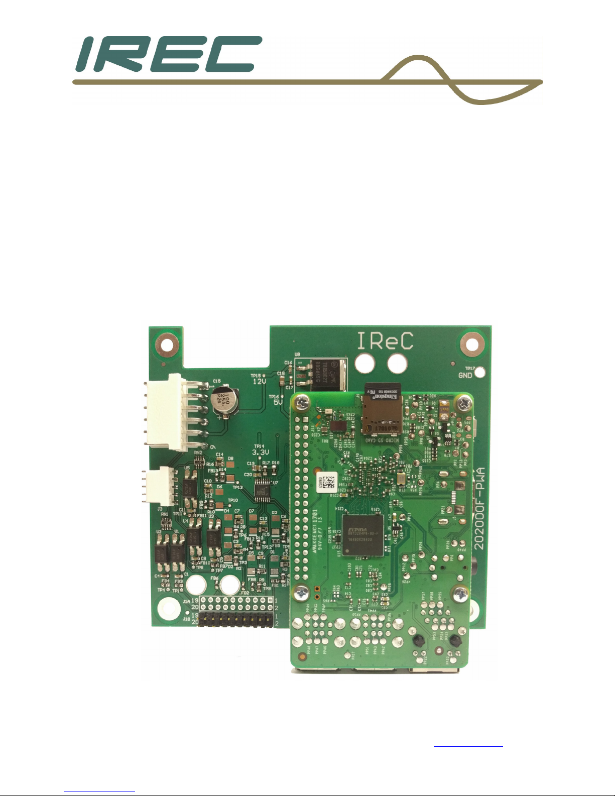
1.1 – Board, wire assemblies, and CD
Open the package to be sure the following items are included
A) Board – IReC-1
B) Wire assemblies:
1) Power, with extra header
2) Flat ribbon cable
3) RJ-45 Male to Female Ethernet cable
4) Small signal cable
C) Mounting hardware
D) Users’ Manual CD – Manual for the unit is listed as IReC-1.pdf
If any items are not included, please contact our of�ice.
Crown Broadcast Phone: 574-262-8900
2524 Toledo Road Fax: 574-970-8909
Elkhart, IN 46516 Service: 866-262-8917
U.S.A. service@irec1.com
5

1.2 – Tools needed for installation
Philips screwdriver with #1 and/or #2 tip
Drill with 1/8” drill bit
Soldering tools – including iron, solder, and solder removing tool
Needle-nose pliers
Wire stripping tool
Diagonal cutter
¼” Hex nut driver
Scissors
Vacuum
1.3 Identifying model of transmitter
The age of the unit will determine which portions of instructions will be
necessary during the process of wiring to the motherboard. Crown
Broadcast has made several different versions of motherboards over the
years, so take note of the version being wired.
Most motherboards will have its part number, version and/or date along
the right side or the front edge of the board. Silk-screening was also
used for identi�ication.
In some of the earlier versions, the version revision is part of the foil
pattern along the front edge of the board. All versions will be able to be
used. However, the earlier ones will require some modi�ications to the
wire assemblies before installation as described in detail later.
Crown Broadcast Phone: 574-262-8900
2524 Toledo Road Fax: 574-970-8909
Elkhart, IN 46516 Service: 866-262-8917
U.S.A. service@irec1.com
6

Chapter 2…………………………………………..Installation
Crown Broadcast Phone: 574-262-8900
2524 Toledo Road Fax: 574-970-8909
Elkhart, IN 46516 Service: 866-262-8917
U.S.A. service@irec1.com
7
2.1 – Preparing the unit for installation
The unit will need to be disconnected from the power source and load
and should be on a large �lat surface.
Remove the top cover and screws and set aside.
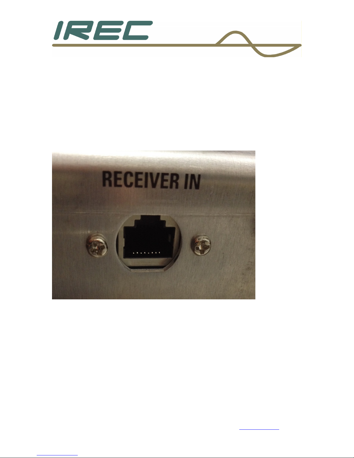
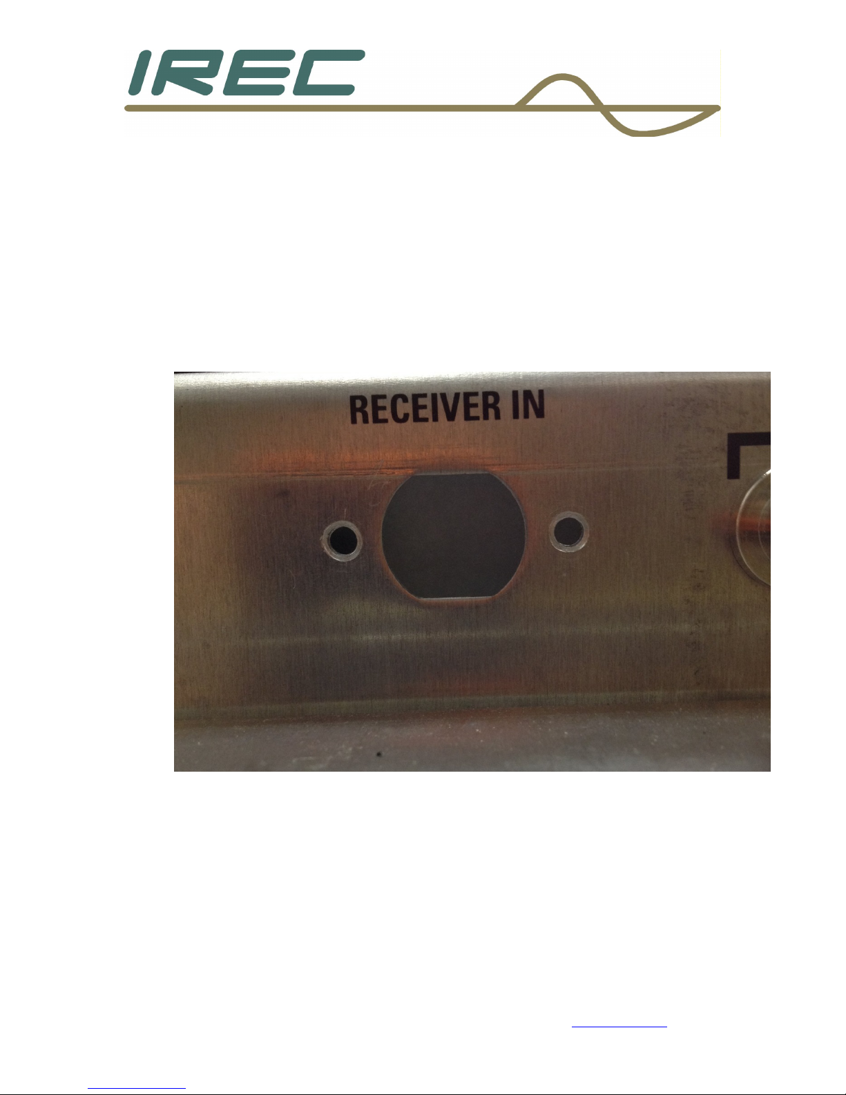
The RJ-45 cable will need to be installed �irst. This will be installed in
the hole for the tuner antenna connector on the back panel. It will be
labeled [RECEIVER IN].
Crown Broadcast Phone: 574-262-8900
2524 Toledo Road Fax: 574-970-8909
Elkhart, IN 46516 Service: 866-262-8917
U.S.A. service@irec1.com
8
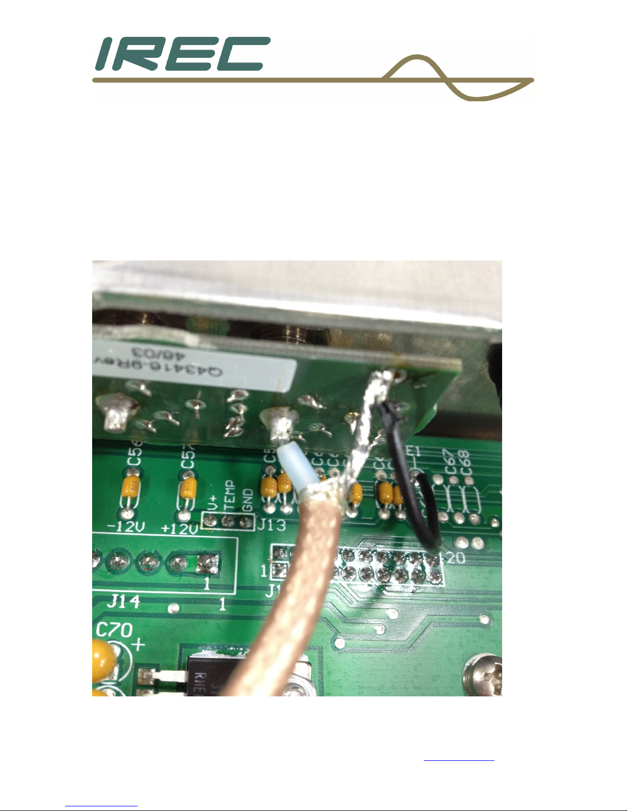
2.1.1 Modifying a unit with a tuner board
If the unit has a tuner, the tuner antenna connection will need to be
changed to one of the unused BNC connectors that are on the back
panel.
If the unit does not have a tuner, skip to section 2.2.
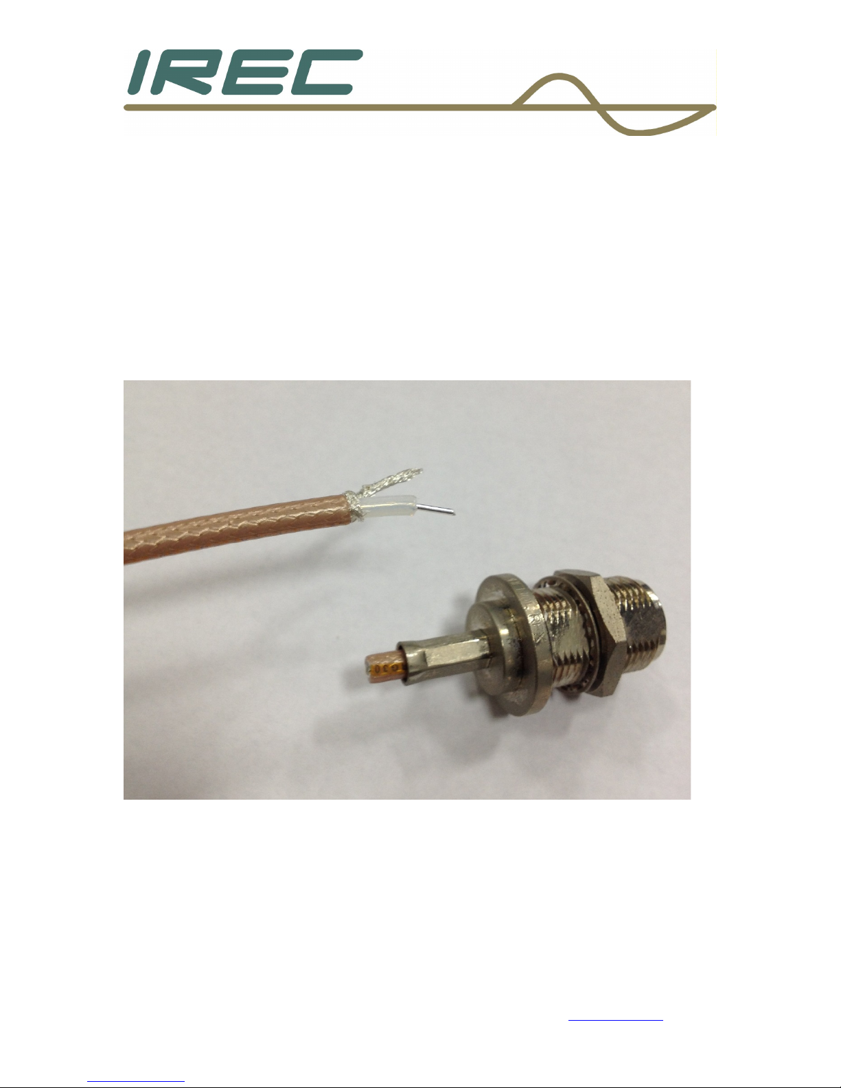
Carefully remove the “N” style connector from the back panel and cut
the connector off. Strip back the insulation ½” and pull the braid back
from one side and twist together as shown below.
Crown Broadcast Phone: 574-262-8900
2524 Toledo Road Fax: 574-970-8909
Elkhart, IN 46516 Service: 866-262-8917
U.S.A. service@irec1.com
9
If the composite connector will not be used, unsolder the wires from
that connector and ty-wrap to the others as shown below. Then solder
the tuner input wires that were prepared to the connector as shown
below.
Crown Broadcast Phone: 574-262-8900
2524 Toledo Road Fax: 574-970-8909
Elkhart, IN 46516 Service: 866-262-8917
U.S.A. service@irec1.com
10
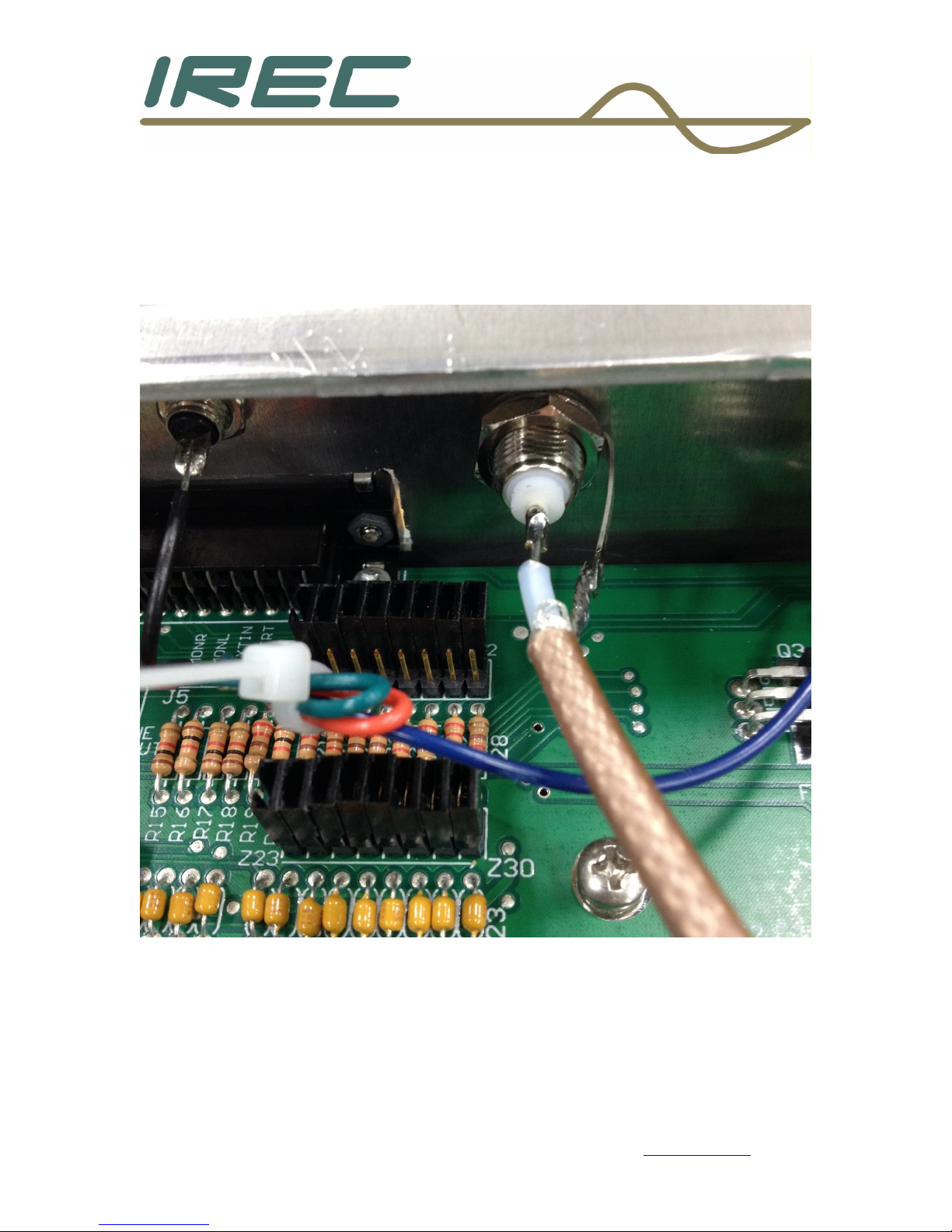
If the composite connector will be used, the only other choice of
connectors will be one of the three used for SCA inputs. It is
recommended to use the farthest one from the tuner to avoid
interference with the cabling installation later. This will require that the
SCA board be removed and the parts associated with this connector be
removed as well. Then, the antenna input wire can be soldered directly
to the board once re-installed as shown below.
Crown Broadcast Phone: 574-262-8900
2524 Toledo Road Fax: 574-970-8909
Elkhart, IN 46516 Service: 866-262-8917
U.S.A. service@irec1.com
11
2.2 Chassis and board mounting
2.2.1 Mounting the RJ-45 into the chassis
A) Locate the black colored hole plug on the back panel under the
label [RECEIVER IN] and remove it.
B) Use a 1/8” drill bit and drill two holes centered exactly 0.175”
from the edge of the hole to the left and right of the hole, centered
vertically to the hole as shown below.
C) These two holes will match the mounting holes contained on
the RJ-45 cable assembly.
D) Clean up any extra metal shavings that may have fallen into the
unit with a vacuum.
Crown Broadcast Phone: 574-262-8900
2524 Toledo Road Fax: 574-970-8909
Elkhart, IN 46516 Service: 866-262-8917
U.S.A. service@irec1.com
12
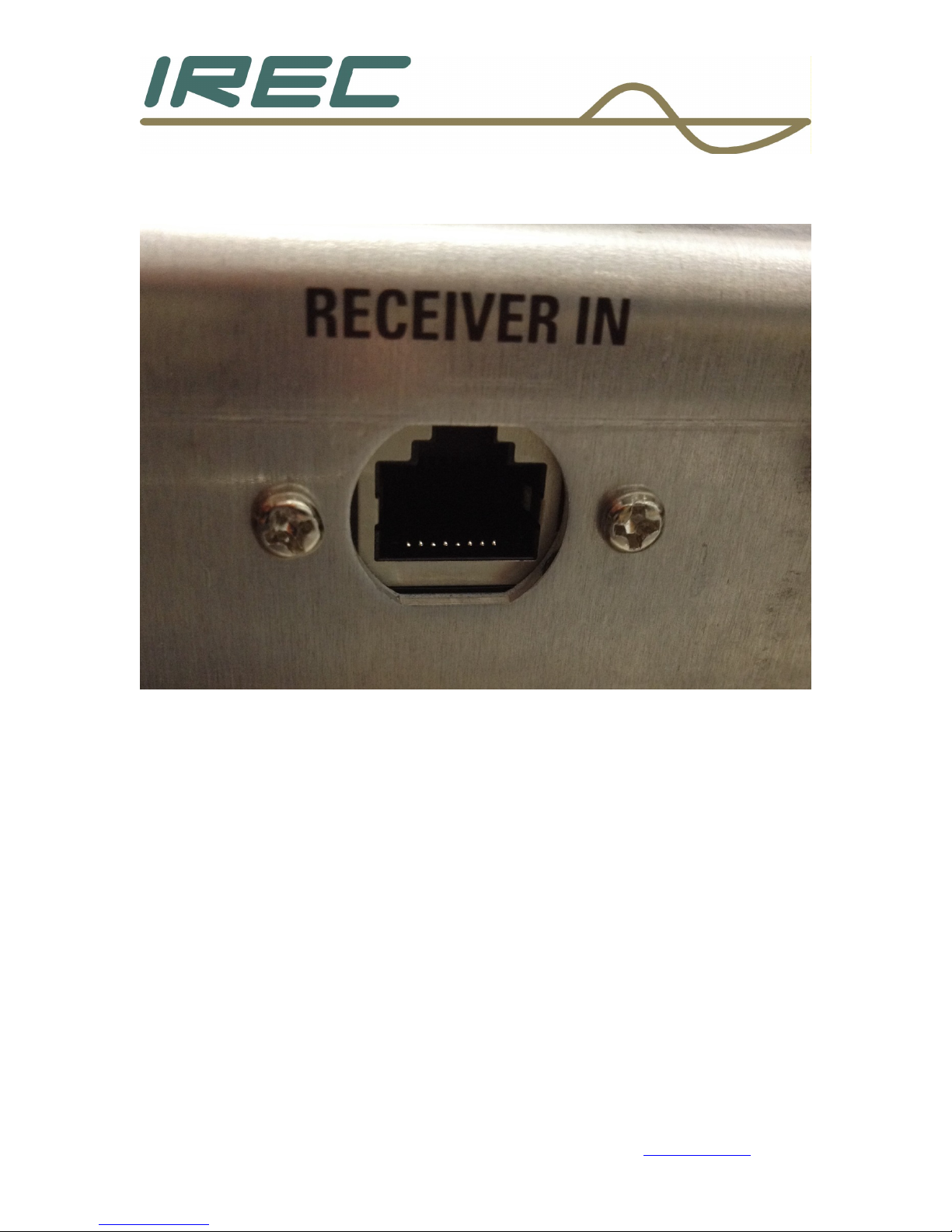
The RJ-45 cable can now be installed into the chassis as shown below
using the provided machine screws mounted in the cable end.
Crown Broadcast Phone: 574-262-8900
2524 Toledo Road Fax: 574-970-8909
Elkhart, IN 46516 Service: 866-262-8917
U.S.A. service@irec1.com
13
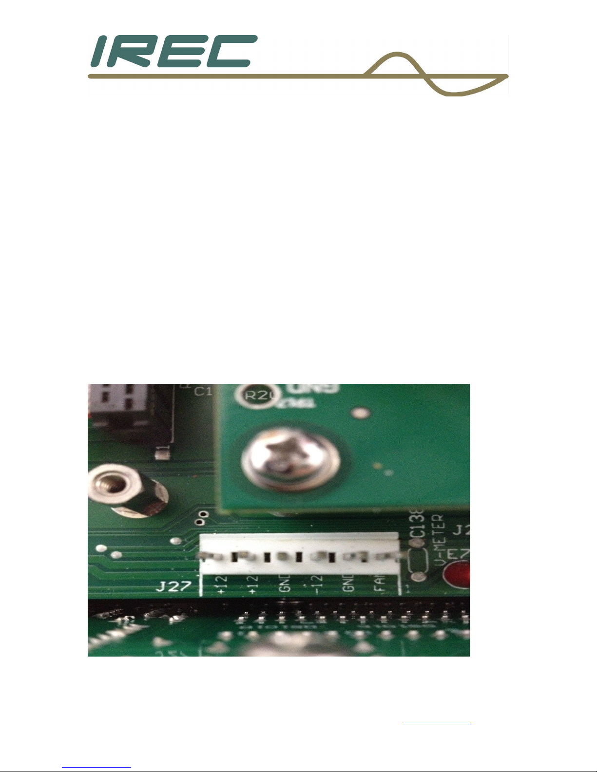
2.2.2 Installing the power connections
Obtain the power wire assembly with the extra header.
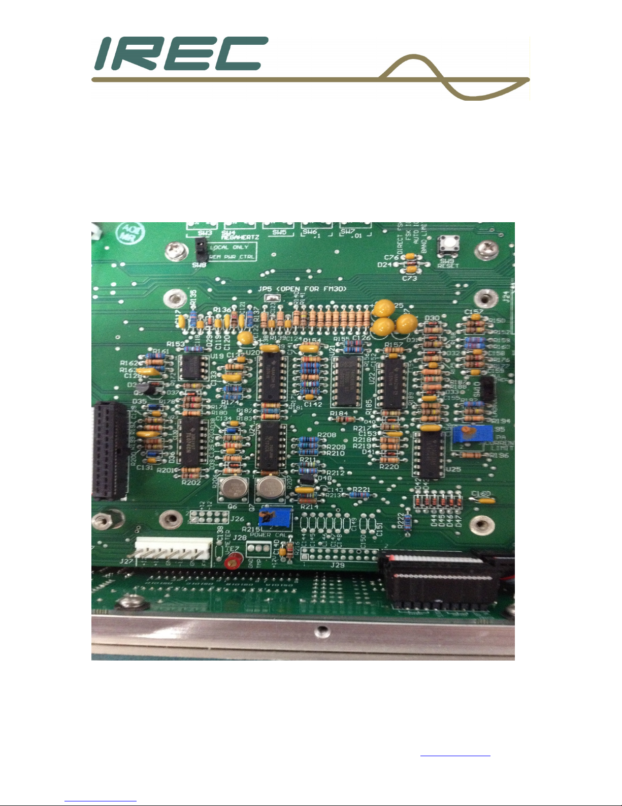
For motherboard revision level of 2007:
A) Using solder wick (or your preferred method to remove solder),
remove the solder in the holes of J27, along the front edge of the
motherboard.
B) Remove front panel assembly (two screws along top left and right
corners and 4 screws along the bottom of the front panel).
Remove the 3 cables that attach to the front panel boards. It is not
necessary to disconnect the Power wires from the switches.
C) Install the header onto the motherboard at location J27 - soldering
in place.
D) Replace front panel assembly.
Crown Broadcast Phone: 574-262-8900
2524 Toledo Road Fax: 574-970-8909
Elkhart, IN 46516 Service: 866-262-8917
U.S.A. service@irec1.com
14

For motherboard revision levels of 2005 and 2006:
A) Remove front panel assembly (two screws along top left and right
corners and 4 screws along the bottom of the front panel). Remove
the 3 cables that attach to the front panel boards. It is not necessary
to disconnect the Power wires from the switches.
B) Unsolder and remove TP2 and TP5 along the front edge of the
motherboard.
C) Remove the solder from these two points.
D) On the power wire, cut one connector off as close to the connector as
possible (black and red wires).
E) Strip and tin the two open wires.
F) Solder the black wire to TP5 (ground).
G) Solder the red wire to TP2 (+12 V).
H) Replace the front panel assembly.
Crown Broadcast Phone: 574-262-8900
2524 Toledo Road Fax: 574-970-8909
Elkhart, IN 46516 Service: 866-262-8917
U.S.A. service@irec1.com
15
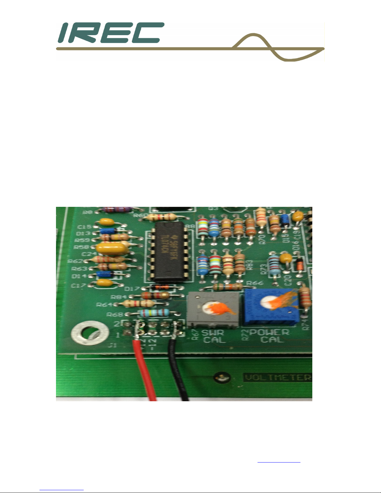
For motherboard revision levels of MAR93 and 2004:
A) On the power wire, cut one connector off as close to the connector as
possible (black and red wires).
B) Strip and tin the two open wires.
C) Solder the black wire to the control/metering board at J1 pins 9 and
10. Care should be taken to avoid melting R67, which is next to the
point of soldering.
D) Solder the red wire to the control/metering board at J1 pins 3 and 4.
Care should be taken to ensure proper soldering with no shorts to
adjacent pads (pins 1 and 2 as well as pins 5 and 6).
Crown Broadcast Phone: 574-262-8900
2524 Toledo Road Fax: 574-970-8909
Elkhart, IN 46516 Service: 866-262-8917
U.S.A. service@irec1.com
16
2.2.3 Mounting the board into the unit
The board hardware can now be mounted.
Remove the 4 screws that hold down the control/meter board. Or, if the
unit has the metering circuits as part of the motherboard, remove the 4
screws surrounding that area as shown below.
Crown Broadcast Phone: 574-262-8900
2524 Toledo Road Fax: 574-970-8909
Elkhart, IN 46516 Service: 866-262-8917
U.S.A. service@irec1.com
17
 Loading...