

Page 1
1 2
3
GBD-II
SHOCK & BREAKAGE
GLASS BREAK DETECTOR
ELECTRONIC ENGI NEERING LTD.
INSTALLATION INSTRUCTIONS
P/N 7101108 Ver. 2.0 A.Y.
The GBD -II is the ultimate answer f or all those
tired of f alse alarms. It listens for sounds of
breaking glass, which produce two sequential
signals of different frequencies. The unique
phased frequency detection circuitry of this
detector allows det ection of both shock signal
and the strong signal of glass breakage
creating a “false alarm free” glass br eak
detector.
The detector does not need to be attached to
the window, providing volume protection, and
allowing you to protect se veral windows with
one detector.
FEATURES
• Phased Frequency Detection system,
detects low frequency impact sound as well
as the glass breakage sound thereby
eliminating false alarms.
• Separate sound & shock adjustment.
• Memory funct ion.
• Volume protection.
• Ceiling or wall mounting.
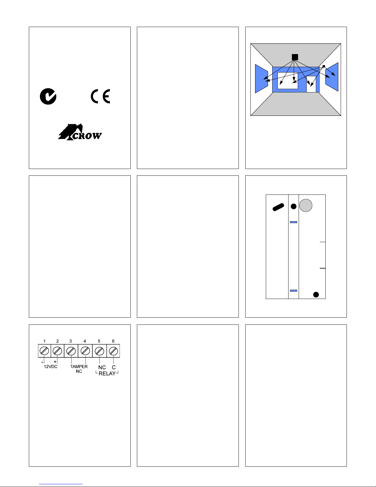
FIG. 1 - MOUNTING
The detector offer s f lexible installation. It can
be Either ceiling mounted or wall mounted as
shown in the figure above.
4 5 6
MOUNTING LOCATION ( See FIG. 1 )
• If heavy blinds or curtains cover the glass,
you must locate the detector behind the
blinds on the window frame or above it,
otherwise the blinds might block the sound.
Make sure to test t he unit thoroughly for
proper detect ion.
• Install the detector in a direct line of sight
with the protected glass.
• Do not mount the unit in fr ont of air ducts,
or close to bells (measuring 0.5m (or
larger) in diameter).
• For a few protected glasses in one room,
locate the detector in optimal distance from
them to achieve the best detection.
Note: for symmetrical cover of the detect ion
area it is recommended to place the
detector on the ceiling.
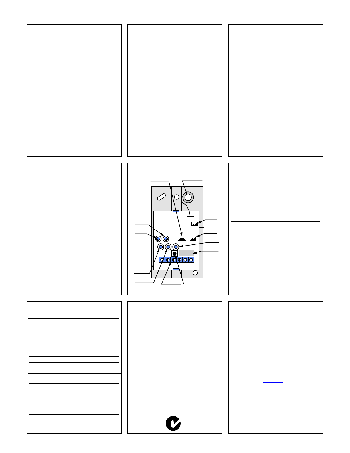
MOUNTING THE DETECTOR ( FIG. 2 )
1. Use a small screwdriver to push the prong
on top of the case and open the case.
2. There is no need to remove the PCB
(Printed Circuit Board) from the case.
3. Insert the wires through the wiring hole (B).
4. Use the mounting holes (A) to mount the
detector.
5. Connect the wires to t he terminal.(See
Terminal Connections)
6. Close the case.
JUMPERS ( FIG . 4 )
• JP1 - Shock / Glass select or f or detection
calibration.
• JP2 - Reduces the sensitivity of sound
detection by 50%.
• JP3 - Lat ch. See The Memory Function.
FIG. 2 - T HE BACK COVER
AAB
7 8 9
FIG. 3 - T ERMINAL BLOCK
TERM INAL BLO CK CONNECTIO NS
Terminal 1 - Marked - ( -12V )
Connect to the negative Voltage output or
ground of the control panel.
Terminal 2 - Marked + ( + 12V )
Connect to the positive Voltage output of 9-16
Vdc source (usually from the alarm control unit)
Terminals 3 & 4 - Marked TAMPER
If a Tamper function is required connect these
terminals to a 24hour normally closed protective
zone in the control unit. If the front cover of the
detector is opened, an immediate alarm signal will
be sent to the control unit.
Terminals 5 & 6 - Marked RELAY
These are the output relay contacts of the detector.
THE CALIBRATION TOO L ( * )
The Simulator/Tester & Calib ration to ol is
especially designed to check phased
frequency glass break detectors.
Since the detector w ill react t o t he high
frequency breakage sound only when it comes
sequentially after a low f r equency SHOCK
sound, this device is necessary to check for
proper operat ion of the GBD-II without actually
breaking the glass.
Manual mode:
In this mode, the Simulator w ill emit the high
frequency sound of breaking glass for "Glass"
adjustment.
Automatic mode:
In order to simulate breaking glass, place the
Simulator on the surface of the protected
glass, and gently hit it with your hand. The
Simulator will then emit the sound of breaking
glass. Be careful not to break the glass while
testing the detector.
∗ It is r ecommended to use simulator CROW
P/N: 0040011
TESTING THE DETECTOR
First use the Simulator in manual mode to
simulate the noise of glass breaking. Check
that the yellow LED is ON. If it does not light,
the sensitivity calibration is necessary (See
Sound Calibration).
Now use your hand or a padded object to
carefully strike the glass. If the green LED
does not light, adjust as necessary (See
Shock Calibration).
Now use the Simulator in automatic mode and
check that the red LED lights. If the red LED is
ON, your detector is wor king properly.
Otherwise try adjusting the sound and shock
setting until the red LED lights.
Page 2
10 11
12
GLASS BREAK ADJUSTMENT
To adjust the glass break setting
(increase/decrease sensitivity) place the
jumper JP1 below the GLASS marking
(connecting the middle pin with the left pin) (See Fig. 4) Gr een LED is constantly ON.
Now you can adjust the sensitivity by rotating
the right potentiometer (marked as GLASS
CALIB. - see Fig. 4).
Operate t he Sound Break Simulator and rotate
the potentiometer clock-wise to increase
sensitivity, and counter-clock-wise to decrease
sensitivity until the Yellow and Red LED’s are
illuminating for each glass break sound.
Remember that rotating the potentiometer will
have no effect upon the settings if the middle
pin of JP1 is not connected to the left p in.
Note
• When the jumper is set for G LASS
adjustment, only the high frequency sound of
breaking glass is detected.
SHOCK ADJUSTMENT
To adjust the shock setting (increase/decrease
sensitivity) place the jumper JP1 below the
SHO CK ma rking (connecti ng the middle pin
with the right pin) - (See Fig. 4) Yellow LED is
constantly ON.
Now you can adjust the sensitivity by rotating
the left potentiometer (marked as SHOCK
CALIB. - see Fig. 4).
Hit gently on the protected glass and rotate
the potentiometer clock-wise to increase
sensitivity, and counter-clock-wise to decrease
sensitivity until the Green and Red LED’s are
illuminating for ea ch hit.
Remember that rotating the potentiometer will
have no effect upon the settings if the middle
pin of JP1 is not connected to the right pin.
Note
• When the jumper is set for SHOCK
adjustment, only the low frequency of the
shock signal prior to glass breakage is
detected.
SENSITIVITY SETTING
For some installations you may find that GBDII is too sensitive. Use JUMPER JP2 to
decrease sensitivity to 50%.
JP2 OPEN - 100% sensitivity
JP2 CONNECTED - 50% sensitivity
FINAL TESTING
• Make sure to disconnect the jumper at
JP1. When the jumper is disconnected, the
detector will detect both shock and sound
frequencies.
• To ensure maximum protection against
false alarms, activate any device in the
area, which might automatically cycle
pumps, generators, heating/air conditioning
units, etc. If the cycling devices trigger an
alarm, mount the unit in a different location.
13 14 15
THE M EMORY FUNCTION
The alarm memory function allows the identification
of an alerting detector out of multiple detectors
connected to one (or the same) zone of the control
panel.
To enable this function, Set on jumper JP3
(connected on both pins - See Fig. 4)
• In case of an alarm,
the red LED will stay
ON until until memory function is reset.
To reset the memory function, switch off
(disconnect)
the voltage wire (+12V) fr om the
TERMINAL BLOCK (See Fig. 4) for minimum
15 seconds then switch on (reconnect) voltage
wire (+12V) .
(The control panel key ON/OFF can be used
for this application if it control the voltage
(+12V).
FIG. 4 - PCB Layout
MICROPHONE
- +
TAMP RELAY
12Vdc
JP1
JP3
JP2
A 50%
SHOCK
CALIB.
JUMPER
JP2
JUMPER JP1
GREEN LED
SHOCK
TAMPER
RELAY
TERMINAL
BLOCK
SOUND
ADJ.
SHOCK
ADJ.
GLASS
CALIB.
LATCH
GAIN
YELLOW LED
GLASS
RED LED
ALARM
JUMPER
JP3
WIRE SIZE REQUIREMENTS
Use #22 AWG (0.5mm) or wires w ith a larger
diameter. Use the following table to determine
required wire gauge (diameter) and length of
wire betw een the detector and the control
panel.
Wire Length m 200 300 400 800
Wire Diameter mm .5 .75 1.0 1.5
Wire Length ft 800 1200 2000 3400
Wire Gauge # 22 20 18 16
16 17 18
TECHNICAL SPECIFICATIONS
Power Input 9 - 16 Vdc
Current Consumption Standby: 22mA at
12Vdc
Active: 25mA at 12Vdc
Detection Range 10m (33ft), Adjustable
Dimensions 93mm x 55mm x 24mm
Mounting Ceiling or Wall
Alarm Output Relay N.C 50mA/24Vdc with
10 Ohm in line resistor
Tamper Switch N.C 50mA 24Vdc with
10 Ohm in line resistor
Operating Temperature -20°C to 50°C
Range (-4°F to 122°F)
Operating Humidity 95% max relative humidity
Range non condensing
Storage Temperature -30°C to 70°C
Range (-22°F to 158°F)
microphone
RFI Protection 30V/m 10 -1000MHz
EMI Protection 50,000V electrical
interference from
CROW LIMITED WARRANTY
(Crow) warr ants this product to be free from defects in materials and workm anship
under normal use and service for a period of one year from the last day of the week and
year whose numbers are printed on the printed circuit board inside this product.
Crow’s obligation is limited to repairing or r eplacing this product, at its option, free of
charge for materials or labor , if it is proved to be defective in materials or workmanship
under nor mal use and ser vice. Cr ow shall have no obligation under this Limited
Warranty or otherwise if the product is altered or improperly repaired or serviced by
anyone other then Crow.
There are no warr anties, expr essed or implied, of mer chantability or fitness for a
particular purpose or otherwise, which extend beyond the description on the face hereof.
In no case s hall Crow be liable to anyone for any consequential or incidental damages
for breach of this or any other warr anty, expr es s ed or implied, or upon any other basis
of liability whatsoever, ev en if the loss or damage is caused by Crow’s own negligence
or fault.
Crow does not repr es ent that this product can not be comprom is ed or cir c um vented;
that this product will prevent any pers on injury or property loss or damage by burglary,
robbery, fire or otherwise; or that this product will in all cases provide adequate warning
or pr otection. P urc has er under stands that a properly ins talled and maintained product
can only reduce the risk of burglary, robbery or other events occurring without providing
an alarm, but it is not insurance or a guarantee that such will not occur or that there will
be no personal injury or property loss or damage as a result. Consequently, Crow shall
have no liability for any per s onal injury; proper ty dam age or any other los s bas ed on
claim that this product failed t o gi ve any warning. However, if Crow is held liable, whether
directly or indirec tly, for any loss or dam age arising under this limited warranty or
otherwise, regardless of cause or origin, Crow’s maximum liability shall not in any case
exceed the pur c has e pric e of this product, which shall be the com plete and exclus ive
remedy against Crow.
CROW ELECTRONIC ENGINEERING LTD.
IS RAEL : 57 Hamelacha St., Holon 58855
Tel: 972-3-5569937 /8 /9
Fax: 972-3-5592981
E-mail:
support@crow.co.il
USA: 2160 North Central Road,
Fort Lee, N.J. 07024
Tel: 1-800-GET CROW
or (201) 944 0005
Fax: (201) 944 1199
E-mail:
AUST RAL IA: 429 Nepean HWY Brighton East Vic 3187
support@crowelec.com
Tel: 61-3-9596 7222
Fax: 61-3-9596 0888
E-mail:
crow@crowaust.com.au
POL AND: VIDICON S P. ZO. O.
15 Povazkow ska St.
01 – 797 Warsaw Poland
Tel: 48 22 562 3000
Fax: 48 22 562 3030
E-mail:
vidicon@vidicon.pl
LATIN AMERICA: CROW LA TIN AMERICA
5753 NW 151
ST
.Street
MIAMI LAK ES,
FL 33014 – USA
Tel: +1-305-823-8700
Fax: +1-305-823-8711
E-mail:
sales@crowlatinamerica.com
ITALY: DEATRONIC
VIA Giulianello 4/14
00178 ROMA, ITALY
Tel: +39-0676-12912
Fax: +39-0676-12601
E-mail:
info@deatronic.com
35108BE50
N345
 Loading...