

Crown FME 350W, FME 2000W, FME 750W, FME 1000W, FME 1500W User Manual
Crown E Series
User’s Manual
FME 350W to FME 2000W BROADCAST TRANSMITTER
87.5 – 108 MHz STEREO AND MULTIPLEX
International Radio & Electronics Corporation
25166 Leer Drive, Elkhart, Indiana, 46514-5425 U.S.A.
web: www.crownbroadcast.com
WITH TCP/IP MONITORING*
*depending on options
©2013 Crown Broadcast, a division of
(574) 262-8900
e-mail: crownbroadcast@irec1.com

Crown Broadcast FME 350W to 2000W User Manual– 05/2013
TABLE OF CONTENTS
1. INTRODUCTION .............................................................................................................................. 6
1.1. Crown Broadcast History ......................................................................................................... 6
1.2. Before you start ....................................................................................................................... 7
2. DESCRIPTION ................................................................................................................................. 8
2.1. General description .................................................................................................................. 8
2.2. Accessories ............................................................................................................................. 8
2.3. Crown Broadcast FME 350 W / 750 W / 1000 W / 1500 W / 2000 W Description .................... 9
2.3.1. Front panel ......................................................................................................................... 9
2.3.2. Rear panel ......................................................................................................................... 10
2.3.3. Opened cover .................................................................................................................... 12
2.3.4. Synoptic .............................................. ..................................... .......................................... 14
2.3.5. 3U Rack ............................................................................................................................. 15
2.4. Protecting the transmitter ........................................................................................................ 15
2.4.1. Surge Protector ................................................................................................................. 15
2.4.2. Protection against VSWR .................................................................................................. 16
2.4.3. Protection against high temperature .................................................................................. 16
2.4.4. Protections incorporated into the PSU ............................................................................... 16
3. TECHNICAL SPECIFICATIONS ..................................................................................................... 17
3.1. RF section .............................................................................................................................. 17
3.2. Composite operation ............................................................................................................... 17
3.3. Stereo operation ..................................................................................................................... 17
3.4. Mono operation ....................................................................................................................... 17
3.5. AF inputs ................................................................................................................................ 18
3.6. HF output ................................................................................................................................ 18
3.7. Power supply .......................................................................................................................... 18
3.1. Interface panel ........................................................................................................................ 19
3.2. Environmental ...................................................................... ........................... ........................ 19
3.3. Physical .................................................................................................................................. 19
3.4. Miscellaneous ................................................................. ........................................................ 20
4. STARTING UP YOUR TRANSMITTER ........................................................................................... 21
4.1. Connecting the transmitter ...................................................................................................... 21
4.2. Using the front panel ............................................................................................................... 22
4.2.1. Setting the transmitter ........................................................................................................ 22
4.2.2. Input selection ................................................................................................................... 23
4.2.3. Setting the MPX inputs ...................................................................................................... 24
4.2.4. MPX configuration ............................................................................................................. 25
4.2.5. Setting the analog or AES inputs ....................................................................................... 26
4.2.6. Getting on air ..................................................................................................................... 26
4.3. Using the PC application......................................................................................................... 27
4.3.1. Connecting with the control software application ............................................................... 27
4.3.2. Setting the transmitter ........................................................................................................ 27
4.3.3. Input selection ................................................................................................................... 27
4.3.4. Setting the MPX inputs ...................................................................................................... 28
4.3.5. MPX configuration ............................................................................................................. 28
4.3.6. Setting the analog or AES inputs ....................................................................................... 28
4.3.7. Getting on air ..................................................................................................................... 28
4.4. With the TCP/IP option ........................................................................................................... 29
4.4.1. Network configuration ........................................................................................................ 29
Page 2
Crown Broadcast, a division of International Radio & Electronics Corporation 25166 Leer Drive, Elkhart, Indiana, 46514-5425 USA
Ph +1 (574) 262 8900

Crown Broadcast FME 350W to 2000W User Manual– 05/2013
4.4.2. Connecting to the web interface ........................................................................................ 29
4.4.3. Configuring the transmitter................................................................................................. 30
4.4.4. Getting on air ..................................................................................................................... 30
5. FRONT SCREEN USE .................................................................................................................... 31
5.1. Overview ................................................................................................................................. 31
5.2. Working principle .................................................................................................................... 31
5.3. Structure of the menus ........................................................................................................... 33
5.3.1. Overview............................................................................................................................ 33
5.3.2. First level measurements ................................................................................................... 34
5.3.3. First level menus ............................................................................................................... 35
5.3.4. TX Parameters menu ......................................................................................................... 36
5.3.5. ALARMS menu .................................................................................................................. 36
5.3.6. Input Switch menu ............................................................................................................. 37
5.3.7. Line1 menu ........................................................................................................................ 38
5.3.8. MPX In menu ..................................................................................................................... 39
5.3.9. Audio Gene menu .............................................................................................................. 40
5.3.10.Modulation menu ............................................................................................................... 41
5.3.11.Stereo encoder menu ........................................................................................................ 42
5.3.12.RDS / SCA encoder menu ................................................................................................. 43
5.3.13.FM limiter menu ................................................................................................................. 44
5.3.14.RDS menu ......................................................................................................................... 45
5.3.15.Network menu ................................................................................................................... 46
5.3.16.COM menu ........................................................................................................................ 47
5.3.17.Power supply menu ........................................................................................................... 48
5.3.18.Temp/Fan menu ................................................................................................................ 49
5.3.19.Time/Date menu ................................................................................................................ 50
5.3.20.License menu .................................................................................................................... 51
5.3.21.About / System menu ........................................................................................................ 52
5.3.22.Easy/Expert menu ............................................................................................................. 53
5.3.23.Exit menu ........................................................................................................................... 53
5.4. Main parameters description ................................................................................................... 54
5.4.1. TX Parameters menu ......................................................................................................... 54
5.4.2. Input Switch menu ............................................................................................................. 54
5.4.3. Line1 menu (ANA) ............................................................................................................. 55
5.4.4. Line2 menu (AES) ............................................................................................................. 56
5.4.5. MPX In menu ..................................................................................................................... 57
5.4.6. Player menu ...................................................................................................................... 57
5.4.7. Audio Gene menu .............................................................................................................. 58
5.4.8. Modulation Menu ............................................................................................................... 58
5.4.9. Stereo Encoder menu ........................................................................................................ 60
5.4.10.RDS / SCA Encoder menu................................................................................................. 61
5.4.11.FM Limiter menu ................................................................................................................ 61
5.4.12.RDS Menu ......................................................................................................................... 63
6. SERIAL & TELNET COMMANDS ................................................................................................... 67
6.1. Working principle .................................................................................................................... 67
6.2. Serial commands .................................................................................................................... 68
6.2.1. System commands ............................................................................................................ 68
6.2.2. Measurement commands .................................................................................................. 69
6.2.3. Configuration commands ................................................................................................... 70
6.2.4. Transmitter commands ...................................................................................................... 71
6.2.5. Alarm commands ............................................................................................................... 72
6.2.6. Input commands ................................................................................................................ 72
6.2.7. Encoder commands ........................................................................................................... 75
Page 3
Crown Broadcast, a division of International Radio & Electronics Corporation 25166 Leer Drive, Elkhart, Indiana, 46514-5425 USA
Ph +1 (574) 262 8900

Crown Broadcast FME 350W to 2000W User Manual– 05/2013
6.2.8. RDS commands ................................................................................................................ 75
6.2.9. Status commands .............................................................................................................. 80
6.2.10.Communication board commands ..................................................................................... 80
7. CONFIGURATION WITH THE PC APPLICATION ......................................................................... 81
7.1. Overview ................................................................................................................................. 81
7.2. Using the application .............................................................................................................. 81
7.2.1. Connection ........................................................................................................................ 81
7.2.2. Configuration ..................................................................................................................... 82
7.2.3. Saving parameters ............................................................................................................. 87
8. REMOTE CONTROL AND MONITORING WITH THE GPIO BOARD ...................................... ..... . 88
8.1. Introduction ............................................................ ................................................................. 88
8.2. Standard GPIO board ............................................................................................................. 88
8.2.1. Description of control and monitoring functions ................................................................. 88
8.2.2. Remote control function pinout .......................................................................................... 89
8.2.3. Remote monitoring function pinout .................................................................................... 89
8.2.4. Physical representation of the GPIOs ................................................................................ 90
8.2.5. Management using serial commands ................................................................................ 91
9. THE EMBEDDED WEBSITE ........................ ................................................................................... 93
9.1. Introduction ............................................................ ................................................................. 93
9.2. Connecting to the embedded web site .................................................................................... 93
9.3. Viewing the Status .................................................................................................................. 95
9.3.1. Advanced measurements .................................................................................................. 95
9.3.2. Main status ........................................................................................................................ 98
9.4. Transmitter configuration ........................................................................................................ 99
9.4.1. Easy configuration ............................................................................................................. 99
9.4.2. Main configuration ........................................................................................................... 100
9.4.3. Modulation configuration .................................................................................................. 101
9.4.4. Input Selection ................................................................................................................. 103
9.4.5. Input Sources .................................................................................................................. 104
9.5. Setting the RDS data ............................................................................................................ 106
9.5.1. Basic encoder .................................................................................................................. 106
9.5.2. Advanced Encoder .......................................................................................................... 108
9.6. System configuration ............................................................................................................ 112
9.6.1. Product ID ........................................................................................................................ 112
9.6.2. Date / Time ...................................................................................................................... 113
9.6.3. Network ........................................................................................................................... 114
9.6.4. Communication ................................................................... ..................................... ........ 114
9.6.5. Users ............................................................................................................................... 115
9.6.6. SNMP Agent .................................................................................................................... 116
9.6.7. Notifications ........................................................................ ............................................. 117
9.6.8. Common traps ................................................................................................................. 118
9.6.9. IRT Traps ......................................................................................................................... 118
9.6.10.Crown Broadcast Traps ................................................................................................... 119
9.6.11.Support .................................. ......................................................................... ................. 119
9.6.12.EMR ................................................................................................................................ 120
9.7. About .................................................................................................................................... 120
10. SERVICE AND SUPPORT ........... ......... ..... .... .......... .... ..... .... ......... ..... ..... ......... .... ..... ......... .... .... 121
10.1. Service.................................................................................................................................. 121
10.2. 24–Hour Support .................................................................................................................. 121
10.3. Spare Parts ........................................................................................................................... 121
10.4. Factory Service Instructions .................................................................................................. 122
11. CROWN BROADCAST THREE YEAR LIMITED PRODUCT WARRANTY . ..... .... ..... .... ..... ..... ... 123
Page 4
Crown Broadcast, a division of International Radio & Electronics Corporation 25166 Leer Drive, Elkhart, Indiana, 46514-5425 USA
Ph +1 (574) 262 8900

Crown Broadcast FME 350W to 2000W User Manual– 05/2013
APPENDIX A: SOFTWARE OPTION MANAGEMENT ..................................................................... 124
A.1. Using the front panel application ............................................................................................. 124
A.2. Using the PC application ......................................................................................................... 125
A.3. Using serial commands ........................................................................................................... 126
APPENDIX B: ADJUSTING THE IMPEDANCE OF ANALOG INPUTS ........................................... 127
APPENDIX C: MAINTENANCE ........................................................................................................ 128
C.1. Changing the fuses ................................................................................................................. 128
C.2. Changing the fan .................................................................................................................... 129
C.3. Changing the surge protector ................................................................................................. 130
APPENDIX D: TROUBLESHOOTING............................................................................................... 131
D.1. Calibration .............................................................................................................................. 131
D.2. Complete Reset of the Crown Broadcast FME ....................................................................... 131
FOR MORE INFORMATION .......... ................................................................................................... 132
Crown Broadcast, a division of International Radio & Electronics Corporation 25166 Leer Drive, Elkhart, Indiana, 46514-5425 USA
Page 5
Ph +1 (574) 262 8900

Crown Broadcast FME 350W to 2000W User Manual– 05/2013
1. INTRODUCTION
1.1. Crown Broadcast History
Crown Broadcast is a division of International Radio & Electronics Corporation located in Elkhart, Indiana.
Crown began as International Radio and Electronics Corporation in 1947. The founder's intent was to
provide high-quality audio equipment and transmitter products to the broadcasting industry.
In the following decades, the company evolved into a world-class supplier of professional audio equipment
and, later, of industrial power supplies and medical imaging power systems. The name of the company was
changed to Crown International in 1975.
In 2000, Crown International was purchased by Harman International, primarily for Crown's Pro Audio
division. As the Crown Broadcast division was not central to the vision of Harman International, remaining
members of Crown's founding family secured the Broadcast division as a separate entity and brought it
under the newly resurrected corporate name of International Radio & Electronics Corporation (IREC).
Today, Crown Broadcast continues to fulfill its mission to provide Best-in-Class FM broadcast transmitter
equipment to its customers by providing highly robust and reliable transmitters worldwide. Crown Broadcast
and WorldCast Systems entered into an agreement allowing Crown Broadcast to add WorldCast’s Ecreso
line of transmitters for distribution, service and support domestically. We believe this will allow our valued
customers the ability to select from a very diverse and fully featured line up including our current product,
now called the Classic line, and the new “E” Series products which will meet all customers’ needs in power
levels up to 10kWs.
Page 6
Crown Broadcast, a division of International Radio & Electronics Corporation 25166 Leer Drive, Elkhart, Indiana, 46514-5425 USA
Ph +1 (574) 262 8900
Crown Broadcast FME 350W to 2000W User Manual– 05/2013
1.2. Before you start
This equipment complies with international mechanical and electrical standards. To maintain this
compliance, as well as to ensure proper and safe working conditions and avoid electrical shocks and fire
hazards, you must comply with the following recommendations:
The device should only be utilized in the conditions described in the user manual.
The device is designed for industrial usage and must only be operated by qualified personnel.
The device may be heavy; it must be lifted and handled with care, specifically during unpacking and
set up.
Electrical precautions
Unplug from mains outlet before any intervention.
Any maintenance, adjustment, or repair must be carried out by personnel specifically trained by
WorldCast Systems.
Before switching on the device, make sure the nominal voltage specified on the device matches the
mains nominal voltage.
The device should only be operated on a stable electrical network. If the electrical network is not
stable, a power conditioner, such as a UPS, must be used.
The device must only be used with a plug that incorporates a protective ground contact.
To avoid any risk of electrocution, the protection conductor must not be cut, intentionally or
accidentally, either on the device or on the power cord.
High quality shielded cables are mandatory.
Environmental precautions
It is necessary to verify that environmental conditions comply with those recommended in the
manual.
Nothing must obstruct the ventilation.
To avoid any electromagnetic interference, the device must only be used when it is closed, installed
in a cabinet and connected to the earth ground as per the instructions.
The device should not be exposed to dripping or splashing and no objects filled with liquids, such as
coffee cups, should be placed on the equipment.
Connectors may be hot on high power units.
Precautions regarding the lithium battery
This device includes a lithium battery.
If the battery is not correctly replaced, there is a risk of explosion.
Only replace it with a battery of the same type. Contact Crown Broadcast before attempting to use another
type.
Do not puncture the battery
Do not throw the battery in fire
Do not immerse the battery in water
Do not throw away the used battery, recycle it instead. You may send it back to us if needed.
If these precautions are not followed, the guarantee will be void.
Crown Broadcast, a division of International Radio & Electronics Corporation 25166 Leer Drive, Elkhart, Indiana, 46514-5425 USA
Page 7
Ph +1 (574) 262 8900

Crown Broadcast FME 350W to 2000W User Manual– 05/2013
2. DESCRIPTION
2.1. General description
Combining the very latest technologies with our proven RF experience, our 350 W, 750 W, 1000 W, 1500 W,
and 2000 W transmitters have been designed to offer an innovative and highly reliable solution.
Among the first FM transmitters based on 6
robust, they also deliver efficiency of up to 74%. Top signal quality and performance are achieved thanks to
the “FM Band Direct to Frequency” digital modulator which is at the heart of this range.
The manufacturing quality and the simplicity of use make these truly powerful transmitters to broadcast
analog FM programs.
The Crown Broadcast FME 350 W, the Crown Broadcast FME 750 W, the Crown Broadcast FME 1000 W,
the Crown Broadcast FME 1500 W, and the Crown Broadcast FME 2000 W are fully protected against
overheating and VSWR.
They also offer a number of built-in functions that can eliminate the additional cost and space requirements
of external equipment.
Fully featured for local maintenance and configuration, they also allow full remote control by Web server,
SNMP, RS232, or GPIOs*.
* Options available with the current version are:
th
Generation MOSFET, these transmitters are not only more
Basic RDS: The internal RDS encoder makes it possible to manage basic RDS parameters (PI, PS,
TP, TA, PTY, MS, DI, radiotext, PTYN, group sequence, AF, 1 PSN, 2 DSN, dynamic scrolling PS).
GPIO: This additional board allows remote control and management of your transmitter.
TCP/IP: This additional board allows remote configuration via a web site and SNMP management.
Please refer to Appendix A for more information on option management.
Project co-financed by the European Union, involved in the Aquitaine Area,
through the European Funds for local development.
2.2. Accessories
The Crown Broadcast FME is supplied with:
1 power cable
1 serial cable
1 USB cable
4 10A fuses (for Crown Broadcast FME 350 W, 750 W and 1000 W only)
1 interlock plug + locks
1 box including 1 CD (documentation + PC application) and 1 quick start notice.
Crown Broadcast, a division of International Radio & Electronics Corporation 25166 Leer Drive, Elkhart, Indiana, 46514-5425 USA
Page 8
Ph +1 (574) 262 8900
Crown Broadcast FME 350W to 2000W User Manual– 05/2013
y
2.3. Crown Broadcast FME 350 W / 750 W / 1000 W / 1500 W / 2000 W Description
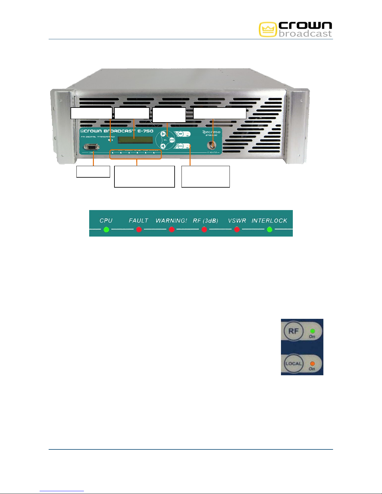
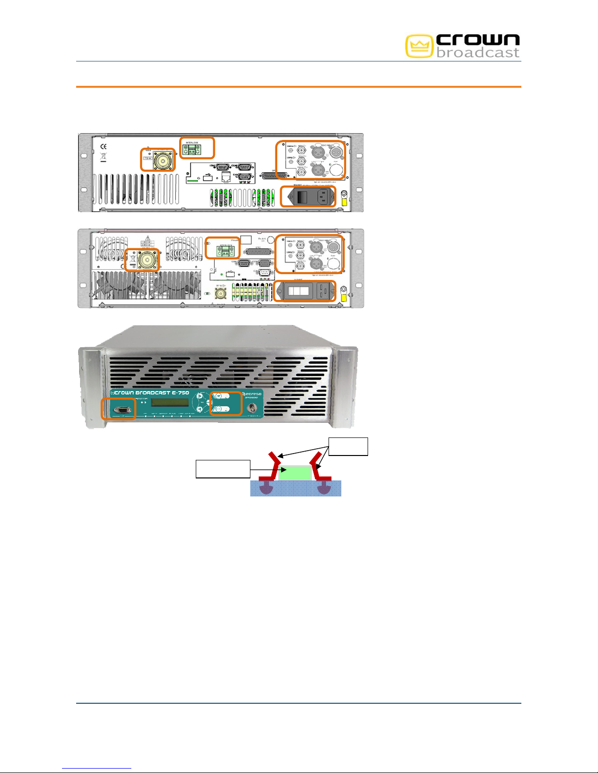
2.3.1. Front panel
LCD contrast Navigation
RS232 port RF on/off and
LCD display
Indicators: CPU, Fault,
Warning, RF (3 dB),
VSWR and Interlock
ke
s
RF monitoring output
local mode keys
and LEDs
Description of indicator LEDs:
CPU: Blinks to indicate CPU activity
FAULT: Major fault of the unit (RF / VSWR protection, Temperature, …)
WARNING: Minor fault of the unit (ambient temperature, radiator temperature, fan, current, voltage,
loss of signal).
VSWR: VSWR of the unit
RF (3dB) : 3 dB of the unit
INTERLOCK: Indicates that internal or external safety links are not activated
RF: Indicates that the unit is on RF=ON. Associated to the RF button.
LOCAL: Indicates that the unit is in local mode. Associated to the Local button.
Page 9
Crown Broadcast, a division of International Radio & Electronics Corporation 25166 Leer Drive, Elkhart, Indiana, 46514-5425 USA
Ph +1 (574) 262 8900
Crown Broadcast FME 350W to 2000W User Manual– 05/2013
(op
(op
)
(
)
(
(op
(op
)
(
)
(
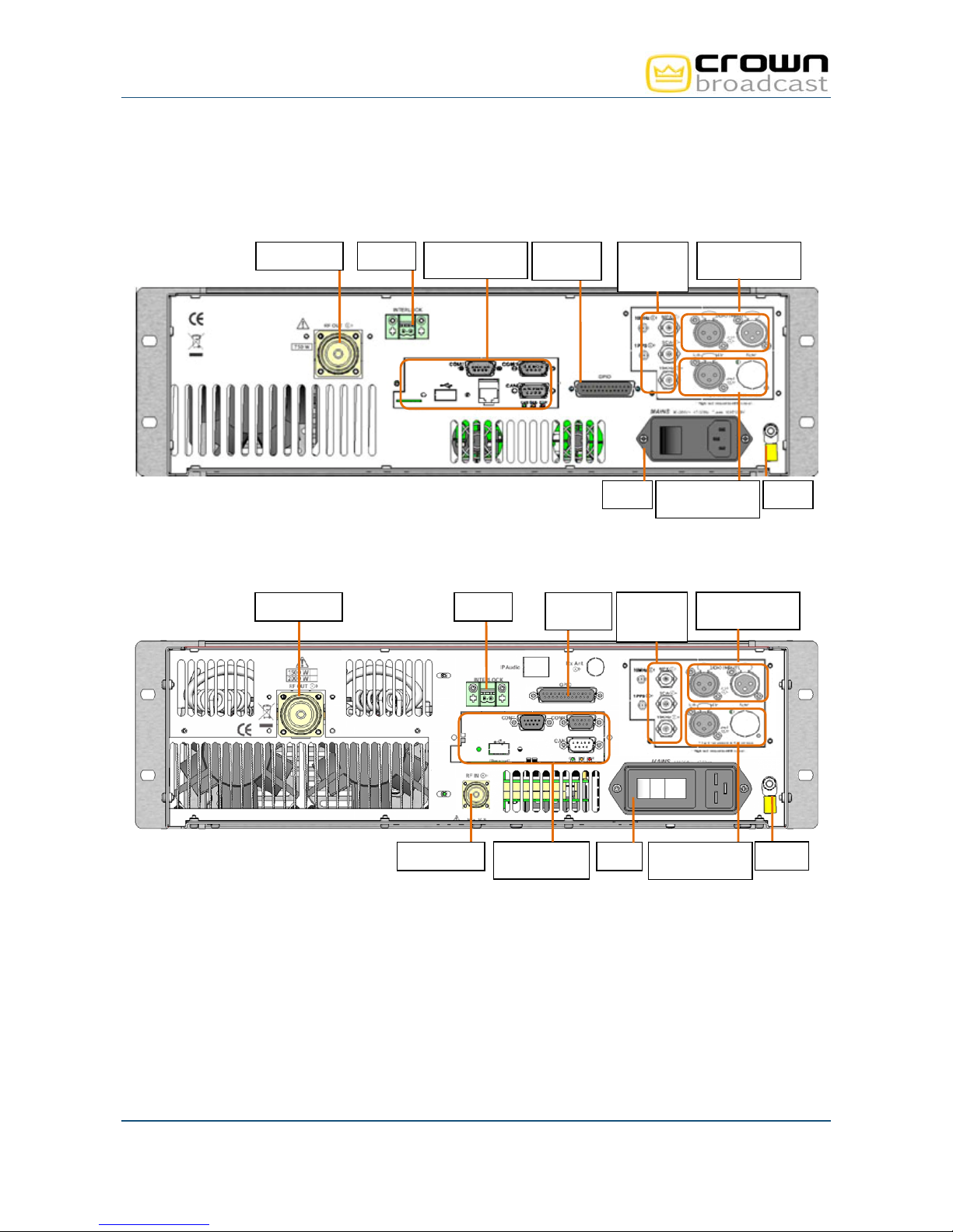
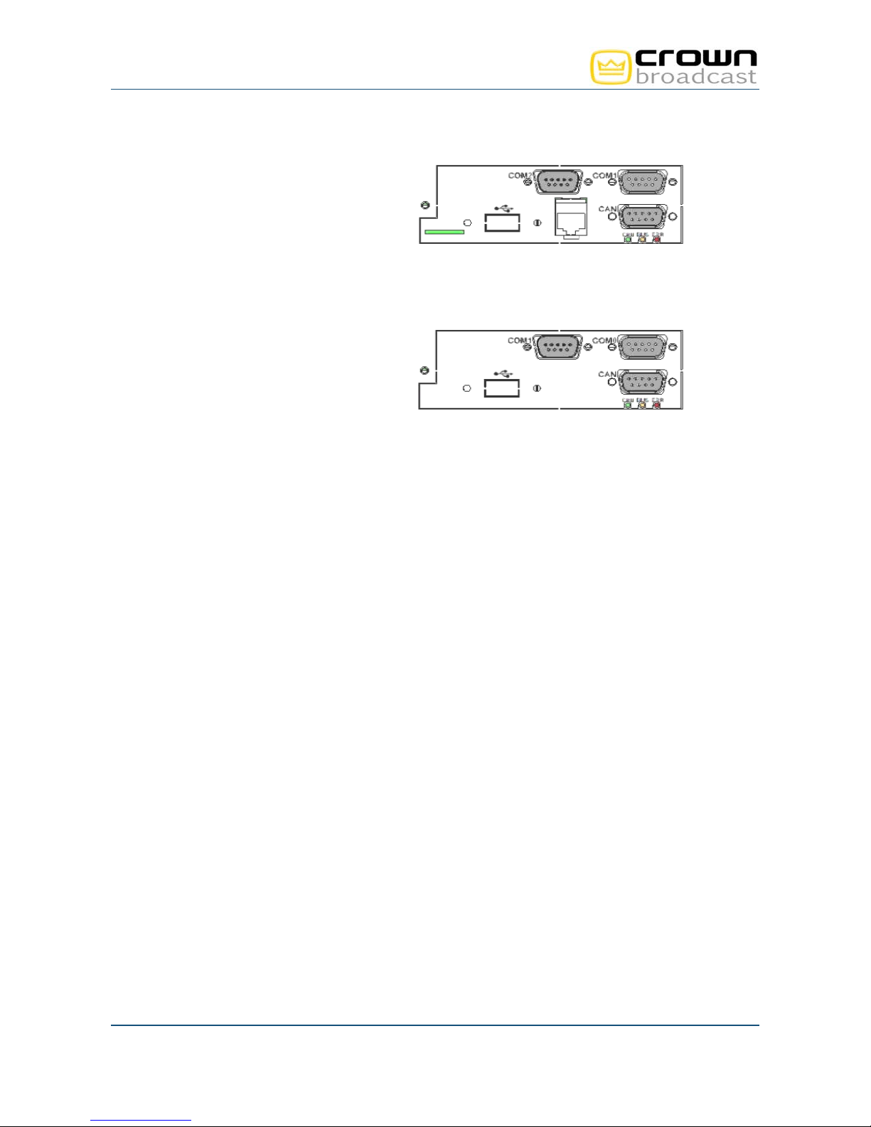
2.3.2. Rear panel
Crown Broadcast FME 350 W / 750 W / 1000 W
7/16 RF output Communication
Interlock GPIO
board
tion) *
tion
MPX/SCA1
MPX/SCA2
19 kHz
Audio input Line1
Ana or AES
Mains
Audio input Line2
Ana or AES)
Ground
Crown Broadcast FME 1500 W / 2000 W
7/16 RF output Interlock
GPIO
tion
MPX/SCA1
MPX/SCA2
19 kHz
Audio input Line1
Ana or AES
Crown Broadcast, a division of International Radio & Electronics Corporation 25166 Leer Drive, Elkhart, Indiana, 46514-5425 USA
N RF input
Page 10
Ph +1 (574) 262 8900
board
tion) *
Mains
Audio input Line2
Ana or AES)
Ground Communication
Crown Broadcast FME 350W to 2000W User Manual– 05/2013
* Two optional communication boards are available:
TCP/IP board
2 RS232 ports (COM1 and COM2)
1 µSD card
1 USB port
1 Ethernet port
1 CAN port
On the TCP/IP board, the COM1 port is used to send serial commands and the COM2 port is used for
dynamic PS tags.
CAN board
2 RS232 ports (COM0 and COM1)
1 slave USB port
1 CAN port
On the CAN board, the COM0 port is reserved for the unit’s upgrade and the COM1 port is used to send
serial commands.
Crown Broadcast, a division of International Radio & Electronics Corporation 25166 Leer Drive, Elkhart, Indiana, 46514-5425 USA
Page 11
Ph +1 (574) 262 8900
Crown Broadcast FME 350W to 2000W User Manual– 05/2013
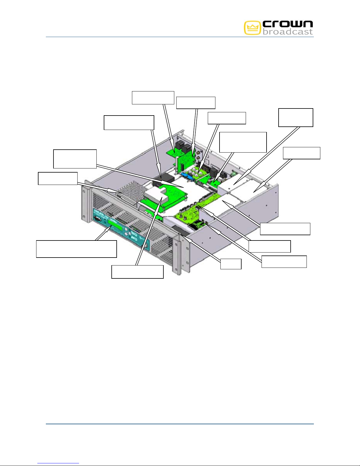
2.3.3. Opened cover
Crown Broadcast FME 350 W / 750 W / 1000 W
Mains filter
Surge protector
Audio inputs
GPIO board
RF output
detection
Communication
board
High output
Output filter
power supply
Power bloc
LCD display
on control/display board
Digital modulator
Fans
RF amplifier bloc
Control board
RF input board
Crown Broadcast, a division of International Radio & Electronics Corporation 25166 Leer Drive, Elkhart, Indiana, 46514-5425 USA
Page 12
Ph +1 (574) 262 8900
Crown Broadcast FME 350W to 2000W User Manual– 05/2013
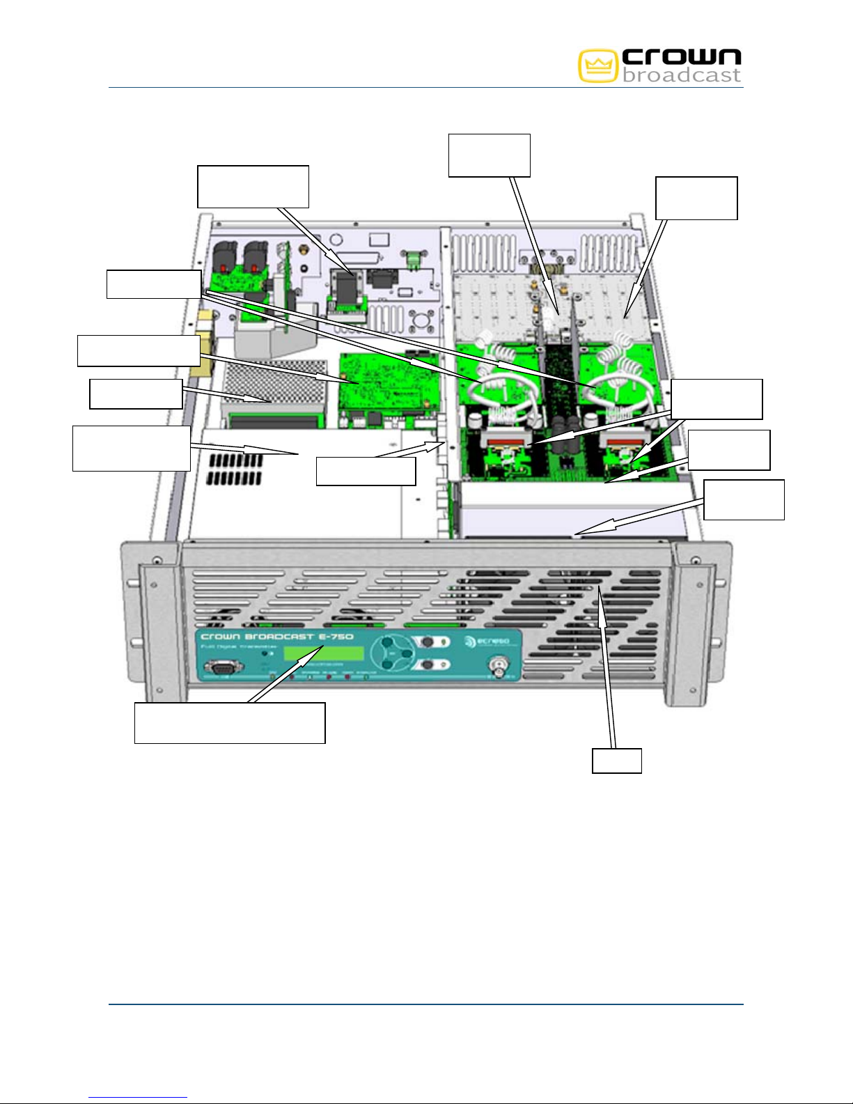
p
Crown Broadcast FME 1500 W / 2000 W
Communication
board
RF output
detection
Output
combiner
Output filters
Digital modulator
Power bloc
High output
power supply
on control/display board
LCD display
Control board
RF amplifier
blocs
Input
s
litter
RF input
board
Fans
Crown Broadcast, a division of International Radio & Electronics Corporation 25166 Leer Drive, Elkhart, Indiana, 46514-5425 USA
Page 13
Ph +1 (574) 262 8900
Crown Broadcast FME 350W to 2000W User Manual– 05/2013
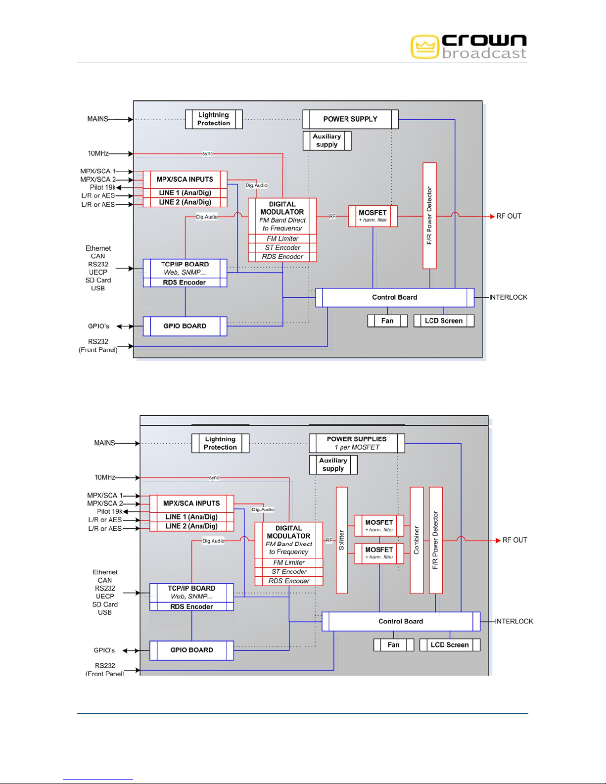
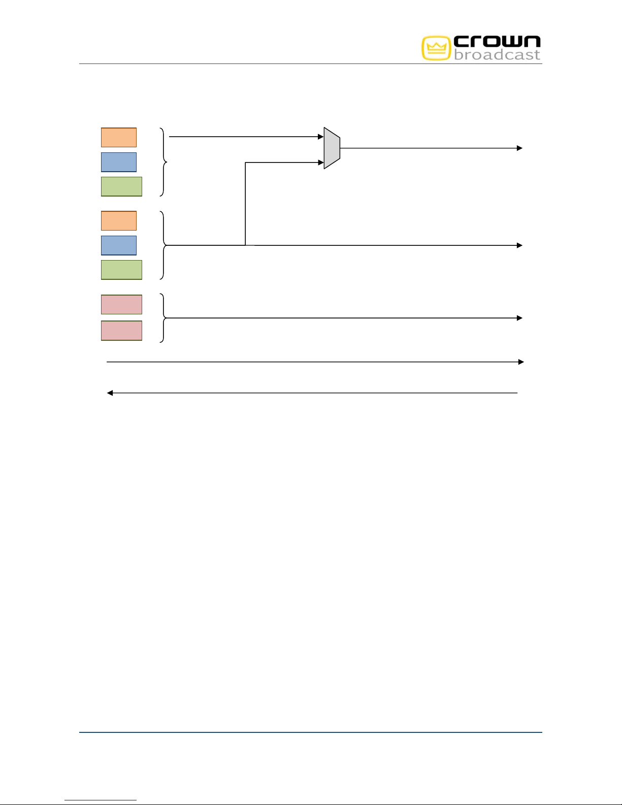
2.3.4. Synoptic
Crown Broadcast FME 350 W / 750 W / 1000 W
Crown Broadcast FME 1500 W / 2000 W
Crown Broadcast, a division of International Radio & Electronics Corporation 25166 Leer Drive, Elkhart, Indiana, 46514-5425 USA
Page 14
Ph +1 (574) 262 8900
Crown Broadcast FME 350W to 2000W User Manual– 05/2013
Audio
G1
Audio 1
D1
AES1
G2
D2
Audio 2
AES2
MPX
SCA
Internal player
19 kHz output
2.3.5. 3U Rack
The choice of stainless steel as material guarantees against corrosion. The rack structure and the structure
of the monoblock front panel reinforce the device. The rectangular outline of the front panel has an LCD
display. The transport handles are mechanically interchangeable and can be removed. The cover is fixed by
a set of M3 POZIDRIV screws and can be easily removed. The user has access to every module to set the
parameters of the device.
2.4. Protecting the transmitter
To ensure the transmitter will work with no risk of damage, a series of protections has been set.
2.4.1. Surge Protector
An optional surge protector module can be added to the chassis. The goal of this module is to limit the surge
caused by lightning. It works after the main protector usually located in the electrical board and before the
power supply protector, thus offering an optimal level of protection. The protector principle is to capture the
surge and divert it to the ground so as to protect the transmitter and its power supplies.
The surge protector used by Crown Broadcast includes multi-MOV technology and a gas discharge tube
(GDT) giving a very high protection and very low parasitic capacitance and leakage currents.
Please refer to Appendix B ‘Maintenance’ for the procedure to replace the surge protection module.
Crown Broadcast, a division of International Radio & Electronics Corporation 25166 Leer Drive, Elkhart, Indiana, 46514-5425 USA
Page 15
Ph +1 (574) 262 8900

Crown Broadcast FME 350W to 2000W User Manual– 05/2013
2.4.2. Protection against VSWR
Several systems coexist to offer the optimal protection against VSWR:
Hardware protection:
In case of open circuit or short-circuit, the RF is cut. When the situation returns to normal, it is
automatically reset.
Software protection:
The reflected power is limited to 3 W for Crown Broadcast FME 20 W, to 10 W for Crown Broadcast
FME 100 W, to 40 W for Crown Broadcast FME 350 W / 750 W / 1000 W and to 80 W for Crown
Broadcast FME 1500 W / 2000 W.
Software settings for the reflected power security management (see VSWR Trip, section 5.4.1).
2.4.3. Protection against high temperature
The Power Supply module includes its own protector against high temperature. The protector cuts off the
power supply output voltage if the temperature is abnormally high. When the situation returns to normal, it is
automatically reset. The temperature threshold value varies depending on the PSU.
The ambient temperature and the radiator temperature are monitored.
The max ambient temperature is set by software (see menu Temp/Fan, section 5.3.18) Default
value is 50°C. In case of overshoot, a Warning alarm is triggered (Alarm Amb).
The max radiator temperature is set by serial command (see serial command CONF.HEAT.MAX,
section 6.2.3). Default value is 65°C. In case of overshoot, a Warning alarm is triggered (Alarm
Heat).
The max internal temperature is set at 70°C. If the temperature exceeds 70°C, the RF is cut off and
a fault alarm is triggered (Alarm Temp).
2.4.4. Protections incorporated into the PSU
The main power supply voltage and the auxiliary power supply voltage are monitored as follows:
Main power supply:
If the difference between the measured voltage and the expected voltage is greater than 10%, a
Warning alarm is triggered (Alarm Volt1). Expected voltage is automatically computed.
Auxiliary power supply:
Voltage should be either 5, 12 or -12 V. If the difference between the measured voltage and the
nominal voltage is greater than 10%, a Warning alarm is triggered (Alarm Volt Aux).
The amperage is also measured. The threshold varies depending of the power of the Crown Broadcast FME:
2 A for the Crown Broadcast FME 20 W, 8.5 A for the Crown Broadcast FME 100 W, 20 A for the Crown
Broadcast FME 350 W, 23 A for the Crown Broadcast FME 750 W, 29 A for the Crown Broadcast FME 1000
W, 26 A per amplifier pallet for the Crown Broadcast FME 1500 W, 31 A per amplifier pallet for the Crown
Broadcast FME 2000 W. In case of overshoot, a Warning alarm is triggered (Alarm Cur) and the nominal
power is reduced.
Crown Broadcast, a division of International Radio & Electronics Corporation 25166 Leer Drive, Elkhart, Indiana, 46514-5425 USA
Page 16
Ph +1 (574) 262 8900

Crown Broadcast FME 350W to 2000W User Manual– 05/2013
3. TECHNICAL SPECIFICATIONS
3.1. RF section
Frequency range 87.5 to 108 MHz
Summary of different steps 10 kHz
Frequency stability < 10
Power range 50-350 W, 50-750 W, 50-1000 W, 150-1500 W or 200-2000 W @
Power output Continuously 0-350 W, 0-750 W, 0-1050 W, 0-1550 W or 0-2050 W
Spurious and harmonic suppression > 75 dBc
10 MHz input recommended range -10 dBm to +10 dBm
3.2. Composite operation
Bandwidth > 40 Hz to 53 kHz @ 0.1 dB
> 20 Hz to 60 kHz @ 0.2 dB
> 60 kHz to 80 kHz @ 0.4 dB
Intermodulation distortion < 0.05%
FM S/N ratio > 80 dB RMS @ 75 kHz deviation
AM noise < 0.1% (50 dB) RMS (20-20 000 Hz)
-6
per year
ROS=1.35
3.3. Stereo operation
Bandwidth > 20 Hz to 15 kHz @ 0.1 dB
38 kHz discontinuance > 50 dB
Stereophonic crosstalk > 50 dB
Pre-emphasis 0 µs, 50 µs or 75 µs
3.4. Mono operation
Bandwidth > 40 Hz to 15 kHz @ 0.1 dB
Out of band rejection > 40 dB @ 19 kHz
Pre-emphasis 0 µs, 50 µs or 75 µs
Page 17
Crown Broadcast, a division of International Radio & Electronics Corporation 25166 Leer Drive, Elkhart, Indiana, 46514-5425 USA
Ph +1 (574) 262 8900

Crown Broadcast FME 350W to 2000W User Manual– 05/2013
3.5. AF inputs
Analog (LINE1)
Connector "XLR" type
Impedance > 10 kΩ by default, adjustable to 600 Ω by jumpers, balanced
Bandwidth Software adjustable
Level Software adjustable (-18/+18 dBu range)
AES (LINE2)
Connector "XLR" type
Impedance > 110 Ω balanced
Bandwidth Software adjustable
Level Software adjustable (-20 to 0 dBFS range)
Sampling rate Auto adjusted up to 192 kHz
Bit 16, 24, 32
Multiplex (MPX/SCA)
Connector "BNC" type
Impedance > 5 kΩ unbalanced
Level Software adjustable (-18/+18 dBu range)
3.6. HF output
Connector 7/16 type
Impedance 50 Ω
Monitoring (RF Monitor)
Level
Crown Broadcast FME 350 W / 750 W / 1000 W 10 dBm 3 dB @ 750 W at main output
Crown Broadcast FME 1500 W / 2000 W 10 dBm 3 dB @ 1500 W at main output
Slope 20 x Log (F/98)
Directivity >20 dB in the band
3.7. Power supply
Voltage 184 VAC to 264 VAC
Frequency 47 Hz - 63 Hz
Max consumption 550 W @ nominal power (350 W version)
1150 W @ nominal power (750 W version)
1550 W @ nominal power (1000 W version)
2300 W @ nominal power (1500 W version)
3050 W @ nominal power (2000 W version)
Fuses (for Crown Broadcast FME 350 W / 750W / 1000 W) 10 AT
Page 18
Crown Broadcast, a division of International Radio & Electronics Corporation 25166 Leer Drive, Elkhart, Indiana, 46514-5425 USA
Ph +1 (574) 262 8900

Crown Broadcast FME 350W to 2000W User Manual– 05/2013
3.1. Interface panel
Indicators Green CPU LED: CPU activity
Red FAULT LED: major fault
Yellow WARNING LED: minor fault
Red RF (3 dB) LED: RF fault (3 dB)
Red VSWR LED: VSWR fault
Green INTERLOCK LED: safety interlock
Green RF LED: RF on
Orange LOCAL LED: local mode
Screens Back lighted LCD: displays operating parameters and menus.
Buttons RF, local, +, -- and OK
3.2. Environmental
Nominal operating temperature 5°C to 45°C
Maximum operating temperature 0°C to 50°C
Warehousing temperature -20°C to +70°C
Warehousing time < 10 years
Cooling Internal ventilation
Crown Broadcast FME 350 W: ~20 I/s
Crown Broadcast FME 750 W: ~20 I/s
Crown Broadcast FME 1000 W: ~20 I/s
Crown Broadcast FME 1500 W: ~55 l/s
Crown Broadcast FME 2000 W: ~55 l/s
3.3. Physical
Crown Broadcast FME 350 W / 750 W / 1000 W
Overall dimension 19’’ (482.6 mm) X 3U (133.5 mm) X 470 mm
Rack size without front panel 440.4 X 126.2 X 432 mm (WxHxD)
Enclosure depth required 600 mm
Mounting 19’’enclosure, with 4 M6X12 screws
Weight around 13 kg
Crown Broadcast FME 1500 W / 2000 W
Overall dimension 19’’ (482.6 mm) X 3U (133.5 mm) X 690 mm
Rack size without front panel 440.4 X 126.2 X 620 mm (WxHxD)
Enclosure depth required 700 mm
Mounting 19’’enclosure, with 4 M6X12 screws
Weight around 18 kg
Page 19
Crown Broadcast, a division of International Radio & Electronics Corporation 25166 Leer Drive, Elkhart, Indiana, 46514-5425 USA
Ph +1 (574) 262 8900

Crown Broadcast FME 350W to 2000W User Manual– 05/2013
3.4. Miscellaneous
Marking CE
Standards 1999/5/CE (R&TTE)
ETS 302 018 (EMC)
ETS 300 384 (Radio)
NF EN 60215 (Safety)
Typical performances un less otherwise noted
Crown Broadcast, a division of International Radio & Electronics Corporation 25166 Leer Drive, Elkhart, Indiana, 46514-5425 USA
Page 20
Ph +1 (574) 262 8900
Crown Broadcast FME 350W to 2000W User Manual– 05/2013
4. STARTING UP YOUR TRANSMITTER
4.1. Connecting the transmitter
1*
2
3
Rear panel
Crown Broadcast FME 350 W / 750
W / 1000 W
5
1*
3
2
Rear panel
Crown Broadcast FME 1500 W /
2000 W
5
Front panel all versions
4
6
* Secure the interlock plug if needed:
locks
Interlock plug
1. Make sure the interlock plug is present on the rear panel; secure it using the provided locks if needed.
2. Connect the transmitter RF output to a 50 load with a wattmeter.
3. The 50 charge power must be greater than 500 W for a 350 W transmitter, greater than 1000 W for a
750 W transmitter, greater than 1250 for a 1000 W transmitter, greater than 1875 W for a 1500 W
transmitter, and greater than 2500 W for a 2000 W transmitter.
When you acquired your transmitter, the RF amplifier is deactivated and power is set to 0 W. These
settings can be adjusted using the PC application, the front panel application or serial commands.
4. Connect the audio or MPX inputs.
5. To use the PC application or the serial commands, connect a PC to the serial port on the front panel of
the Crown Broadcast Transmitter.
If your PC does not have a RS-232 port, use a USB/RS-232 cable.
6. Connect to power using the provided cable; you may unscrew the cable loop and pass the power cable
through it to secure it.
7. Press the Local button on the front panel, then the RF button.
Page 21
Crown Broadcast, a division of International Radio & Electronics Corporation 25166 Leer Drive, Elkhart, Indiana, 46514-5425 USA
Ph +1 (574) 262 8900
Crown Broadcast FME 350W to 2000W User Manual– 05/2013
To configure the transmitter using the front panel: See section 4.2.
To configure the transmitter using the PC application: See section 4.3.
To set network parameters (TCP/IO option only): See section 4.4.
To use serial commands: See section 6.
4.2. Using the front panel
Please refer to section 5.2 for front panel working principle.
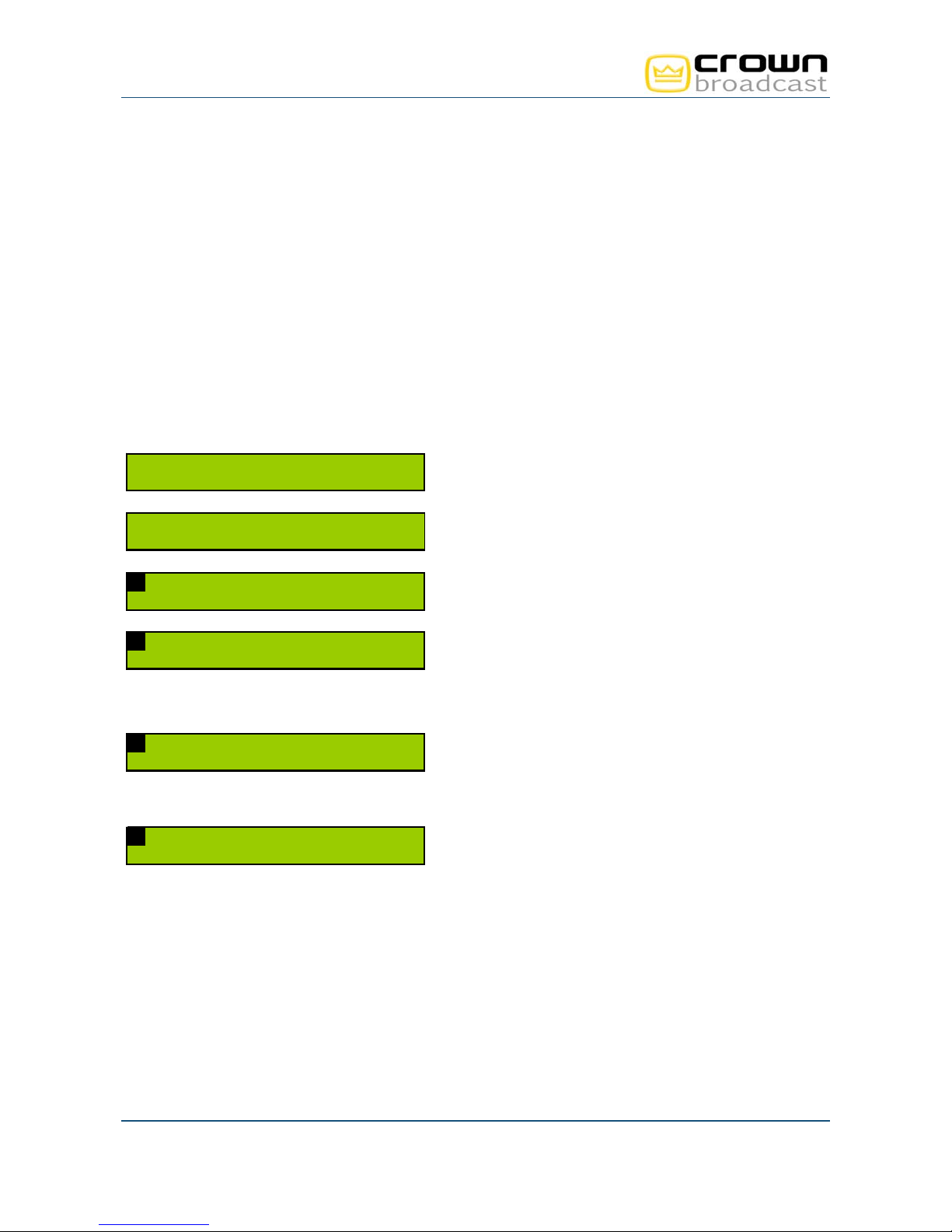
4.2.1. Setting the transmitter
Set the power (in W), the frequency (in MHz) and enable the RF:
98 . 00MHz 0W
98 . 00MHz 0W
->TX PARAMETERS>
1 FREQ PFWD
-> 9 8 . 0 0 0
From the main screen, press the "Enter” key to display
menus and then the “+” key until you see the TX
Parameters menu.
Once you see this screen, press “Enter”.
You may now set the frequency and the power. The arrow
preceding the frequency indicates that this parameter is
selected. Press “Enter” to switch to edit mode.
1 FREQ PFWD
-> 9 8 . 0 0 0
1 FREQ PFWD
104 . 05 -> 0
1 GO T O
MA I N ->RF
Using the “+” and “–” keys, adjust the frequency starting
with the last digit. Once you’ve reached the desired value,
press “Enter” to go to the next digit. Follow the same
procedure for all digits and confirm with the “Enter” key.
Use the "+" to go the next parameter.
The arrow now appears before the power. Set the power
in the same way you set the frequency.
After confirming the power value with the “Enter” key,
enable the RF using the front panel button.
Press the “+” key until you see this screen. When the RF
menu is selected, press “Enter” to return to the list of
menus.
Crown Broadcast, a division of International Radio & Electronics Corporation 25166 Leer Drive, Elkhart, Indiana, 46514-5425 USA
Page 22
Ph +1 (574) 262 8900
Crown Broadcast FME 350W to 2000W User Manual– 05/2013
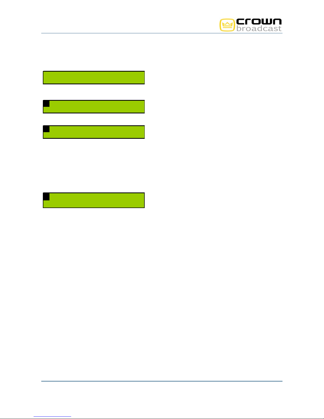
4.2.2. Input selection
G O T O
-> I N P U T S W I T C H >
Press the “+” key until you see the Input Select menu.
Then press the “Enter” key.
1 INPUT SELECT
-> M O D E : M A N U
Browse through the Input Select menu using the “+” and “–
” keys to switch to manual mode.
Select the current input:
1 INPUT SELECT
-> M A I N : L I N E 1
"LINE1" for analog (see sections 9 to 11)
"LINE2" for AES (see sections 9 to 11)
"MPX1" for MPX (see sections 8 and 11)
"MPX2" for MPX (see sections 8 and 11)
"PLAYER": internal generator
Use the “Enter” key to switch to edit mode, the “+” and “–”
keys to adjust values and the “Enter” key to confirm.
1 GO TO
MA I N -> I NPUT SE L
Press the “+” key until you see this screen. When the Input
Sel menu is selected, press “Enter” to return to the list of
menus.
Crown Broadcast, a division of International Radio & Electronics Corporation 25166 Leer Drive, Elkhart, Indiana, 46514-5425 USA
Page 23
Ph +1 (574) 262 8900
Crown Broadcast FME 350W to 2000W User Manual– 05/2013
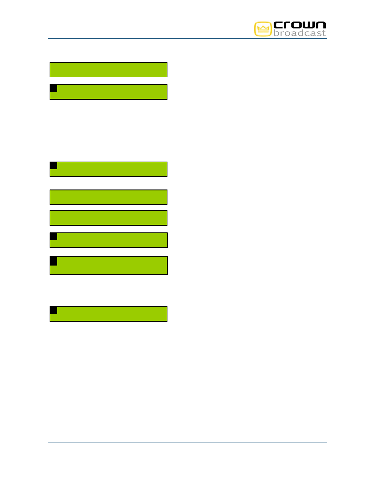
4.2.3. Setting the MPX inputs
GO TO
-> M P X I N >
Press the “+” key until you see the MPX In menu. Then
press the “Enter” key.
1 MPX I N
-> M P X 1 >
Press the “Enter” key once more to set the MPX1 input.
Browse through the MPX1 menu using the “+” and “–”
2 MPX - I N->MPX 1
-> L E V E L : + 0 6 . 0 0
keys to set the nominal level between -50 and +50 dBu,
Use the “Enter” key to switch to edit mode, the “+” and “–”
keys to adjust values and the “Enter” key to confirm.
2 GO TO
->MPX - I N MPX 1
Press the “+” key until you see this screen. When the
MPX-IN menu is selected, press “Enter” to return to main
MPX menu and set the MPX2 input in the same way.
To return to the main screen, press the “+” key until you
1 GO TO
->MA I N MPX - I N
see this screen. When the Main menu is selected, press
“Enter” to return to the list of menus.
Crown Broadcast, a division of International Radio & Electronics Corporation 25166 Leer Drive, Elkhart, Indiana, 46514-5425 USA
Page 24
Ph +1 (574) 262 8900
Crown Broadcast FME 350W to 2000W User Manual– 05/2013
4.2.4. MPX configuration
GO T O
-> S T E N C O D E R >
Press the “+” key until you see the ST Encoder menu.
Then press the “Enter” key.
1 ST ENCODER
-> M O / S T : S T E R E O
1 GO TO
MA I N ->CODER
GO T O
-> S T E N C O D E R >
GO T O
-> M O D U L A T I O N >
1 MOD U L A T I O N
->DEV MPX:127.2
1 MOD U L A T I O N
->DEV PILOT:18.4
1 GO TO
MA I N->MODU L A T I ON
Press once again the “Enter” key to set the audio type.
Select what you need using “+” and “–” keys:
STEREO
MONO
MONO_L
MONO_R
Selecting STEREO enables the internal 19 kHz; you will
therefore want to select MONO for an MPX input.
Confirm with the “Enter” key and press “+” until you see
this screen. When the CODER menu is selected, press
“Enter” to return to the list of menus.
Press the “+” key until you see the Modulation menu.
Then press the “Enter” key.
Browse through the Modulation menu using the “+” and “–”
keys to set the total deviation between 0 and 150 kHz,
Set the pilot deviation between 0 and 25.5 kHz.
For each of these values, use the “Enter” key to switch to
edit mode, the “+” and “–” keys to adjust values and the
“Enter” key to confirm.
Press the “+” key until you see this screen. When the
Modulation menu is selected, press “Enter” to return to the
list of menus.
Crown Broadcast, a division of International Radio & Electronics Corporation 25166 Leer Drive, Elkhart, Indiana, 46514-5425 USA
Page 25
Ph +1 (574) 262 8900
Crown Broadcast FME 350W to 2000W User Manual– 05/2013
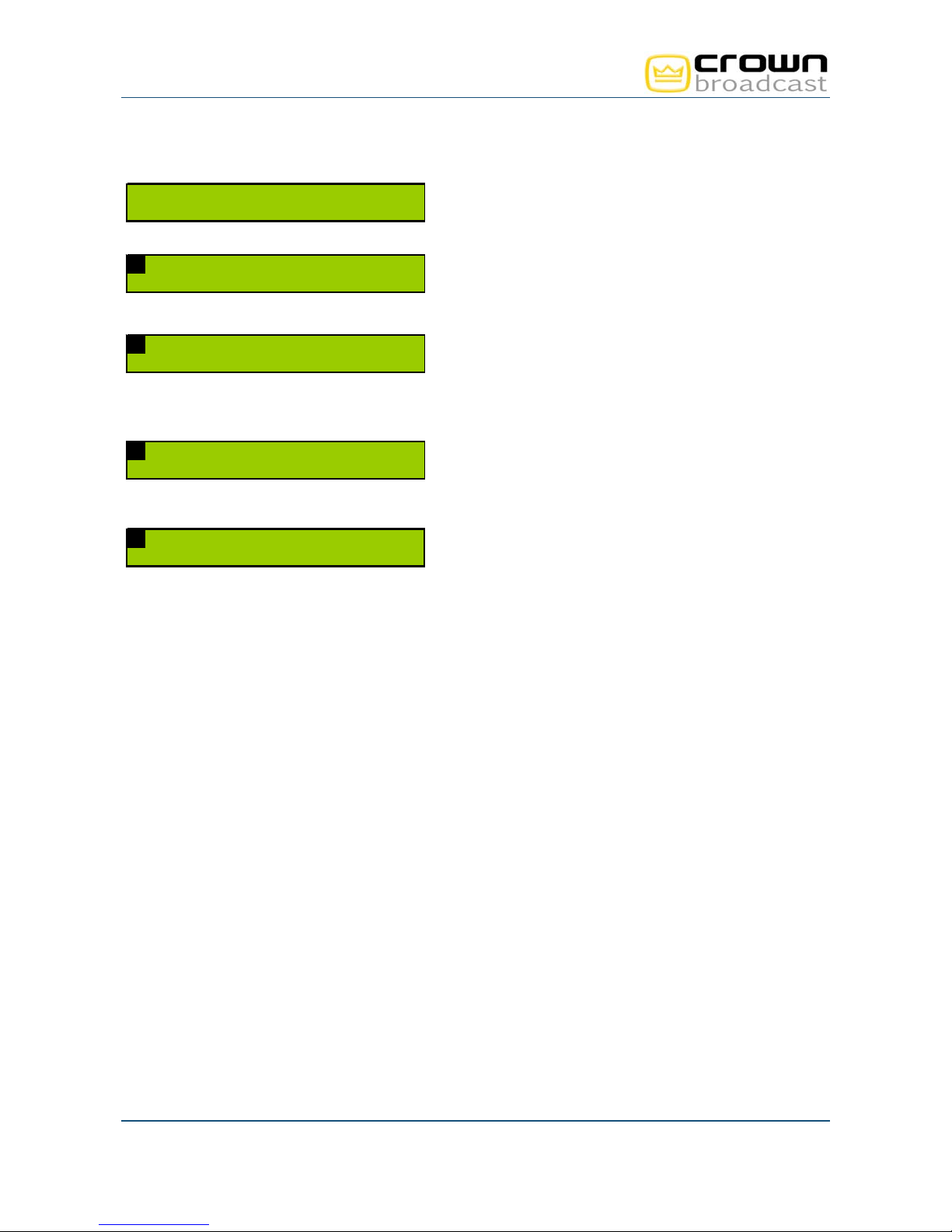
4.2.5. Setting the analog or AES inputs
GO TO
-> L I N E 1 >
Press the “+” key until you see the Line1 (or Line2) menu.
Then press the “Enter” key.
1 LINE1
-> L E V E L : + 0 6 . 0 0
Browse through the Line1 (or Line2) menu using the “+”
and “–” keys to set the nominal level between -50 and +50
dBu.
Use the “Enter” key to switch to edit mode, the “+” and “–”
keys to adjust values and the “Enter” key to confirm.
1 GO TO
MA I N ->L I NE 1
Press the “+” key until you see this screen. When the
Line1 (or Line2) menu is selected, press “Enter” to return
to the list of menus.
Default transmitter pre-accentuation is 50 µs. Depending on your country, you might need to switch it to 75
µs (in the United States, for instance). The pre-accentuation parameter is only visible in Expert mode; you
must therefore first change the front panel working mode:
98.00MHz 100W
->EASY
GO TO
-> L I N E 1 >
1 LINE1
-> P R E A C : 5 0
Press the “+” key until you see the Easy menu. Then press
the “Enter” key, “+” and “Enter” again to switch to Expert
mode.
Go back to the Line1 menu. Press the "Enter" key and
then the “+” key to change the pre-accentuation.
Use the “Enter” key to switch to edit mode, the “+” and “–”
keys to adjust values and the “Enter” key to confirm.
1 GO T O
-> M A I N -> L I N E 1
Press the “+” key until you see this screen. When the
Line1 (or Line2) menu is selected, press “Enter” to return
to the list of menus.
4.2.6. Getting on air
1. Disable the RF using the front panel RF button.
2. Make sure the RF indicator LED is off.
3. Disconnect the load and connect the antenna to the transmitter RF output.
4. Enable the RF again using the front panel RF button.
Crown Broadcast, a division of International Radio & Electronics Corporation 25166 Leer Drive, Elkhart, Indiana, 46514-5425 USA
Page 26
Ph +1 (574) 262 8900
Crown Broadcast FME 350W to 2000W User Manual– 05/2013
4.3. Using the PC application
4.3.1. Connecting with the control software application
1. On the PC, start the control software. This is a set-up tool that will allow you to quickly set and test your
transmitter. It is available on the supplied CD.
On the transmitter’s page, click the control interface link to download the zipped file to your PC.
Extract the .exe file. You do not need to install it: simply double-click on ENGI_REV_xxx.exe to
launch the application.
2. Select the serial port connected to the Crown Broadcast transmitter and the port speed (9600 for the
front panel connector).
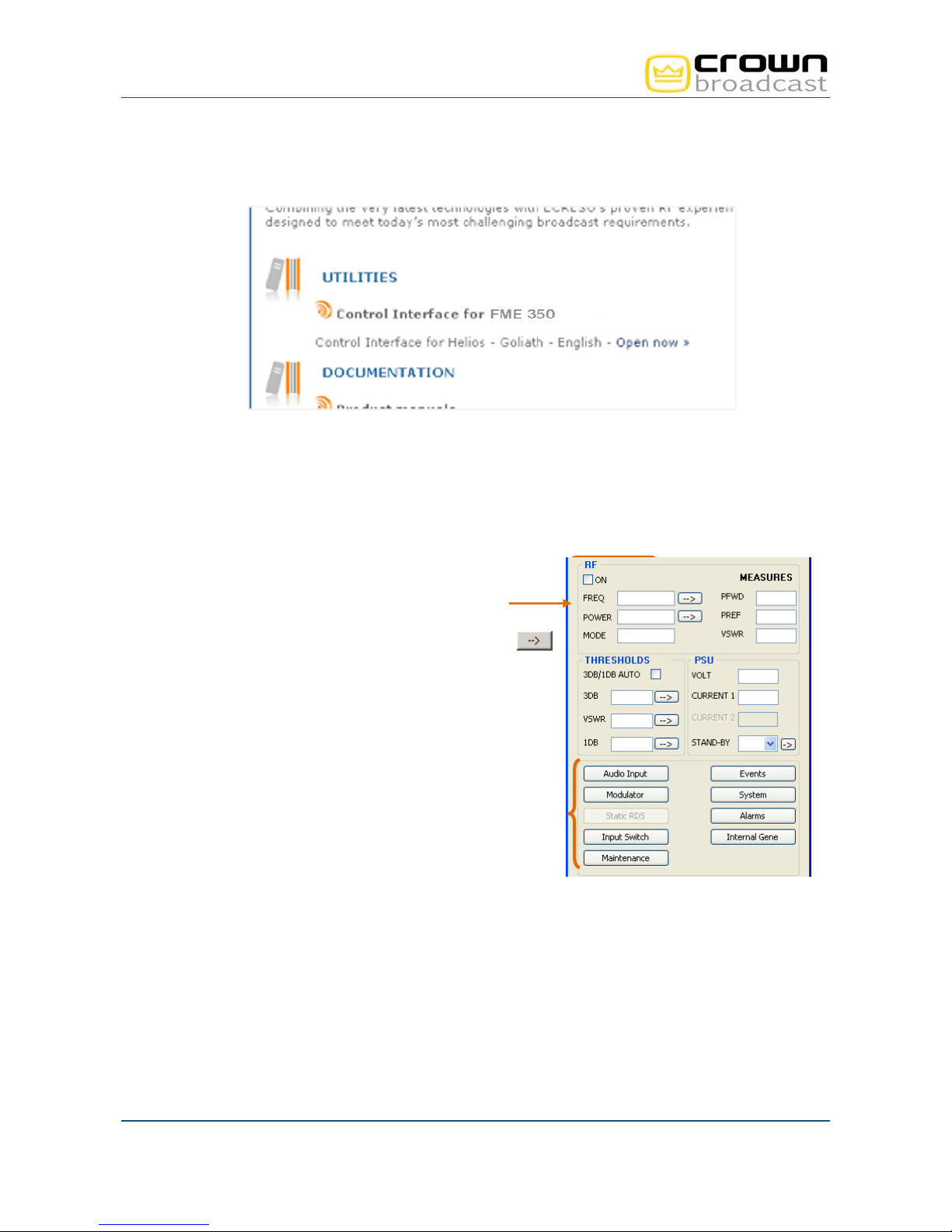
4.3.2. Setting the transmitter
1. Set the power (in W), the frequency (in MHz) and enable the
RF.
2. To send a parameter value to the transmitter, click the login
button; no password is set in the factory. Click the
button to the right of the text zone.
3. A set of buttons give access to other parameters. Click on
one of them to open a window displaying associated
parameters. The “Audio Input” and “Modulator” windows will
enable input and MPX configuration.
4.3.3. Input selection
The input can be set to:
Line1 for the analog inputs (see sections 4.3.4 to 4.3.6)
Line2 for the AES (see sections 4.3.4 to 4.3.6)
MPX1 and MPX2 inputs (see sections 4.3.3 and 4.3.6)
Internal generator
Crown Broadcast, a division of International Radio & Electronics Corporation 25166 Leer Drive, Elkhart, Indiana, 46514-5425 USA
Page 27
Ph +1 (574) 262 8900
Crown Broadcast FME 350W to 2000W User Manual– 05/2013
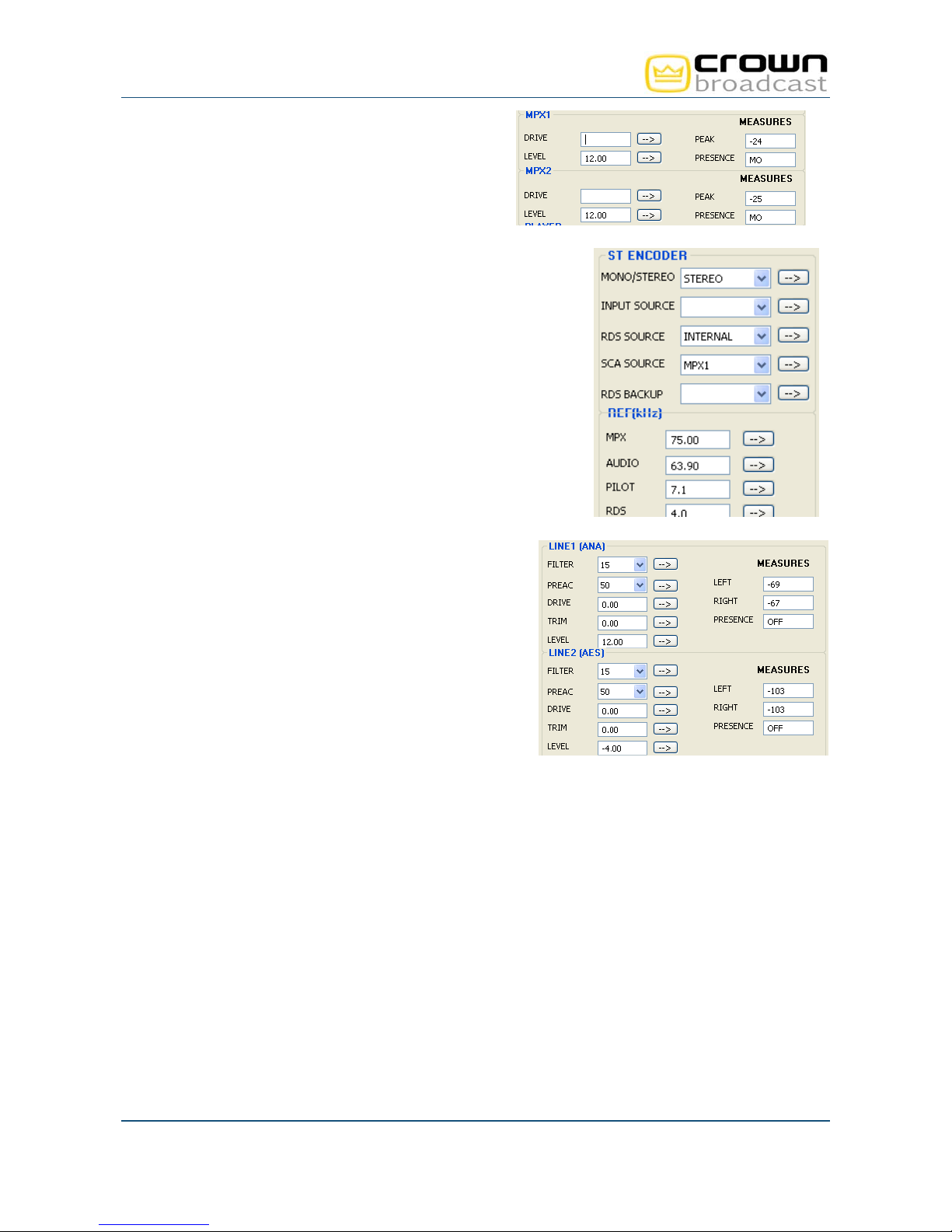
4.3.4. Setting the MPX inputs
Click the "Audio Input" button:
Set the nominal level between -50 and +50 dBu
4.3.5. MPX configuration
Click the "Modulator" button:
Set the audio type to:
o STEREO
o MONO
o MONO_L
o MONO_R
Selecting STEREO enables the internal 19 kHz; you should
therefore select MONO for an MPX input.
Set the total deviation between 0 and 150 kHz
Set the pilot deviation between 0 and 25.5 kHz
4.3.6. Setting the analog or AES inputs
Click the "Audio Input" button:
Set the nominal level between -50 and +50 dBu
Set the pre-emphasis to 0, 50 or 75 µs depending on
your country (50 µs in Europe, 75 µs in the USA).
4.3.7. Getting on air
1. Disable the RF using the front panel RF button.
2. Make sure the RF indicator LED is off.
3. Disconnect the load and connect the antenna to the transmitter RF output.
4. Enable the RF again using the front panel RF button.
Crown Broadcast, a division of International Radio & Electronics Corporation 25166 Leer Drive, Elkhart, Indiana, 46514-5425 USA
Page 28
Ph +1 (574) 262 8900
Crown Broadcast FME 350W to 2000W User Manual– 05/2013
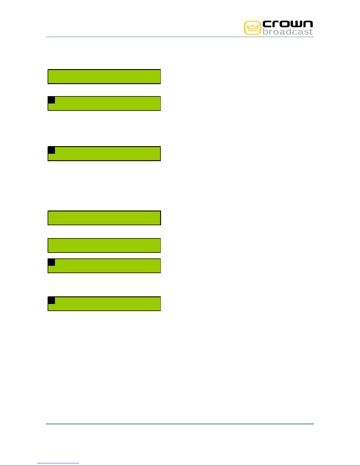
4.4. With the TCP/IP option
4.4.1. Network configuration
If the optional IP board is present on the transmitter, first set the IP address with the front panel:
98 . 00MHz 0W
98 . 00MHz 100W
-> N E T W O R K >
1 NETWORK->ADR
->192 . 168 . 012 . 103
1 NETWORK->MASK
->255 . 255 . 255 . 000
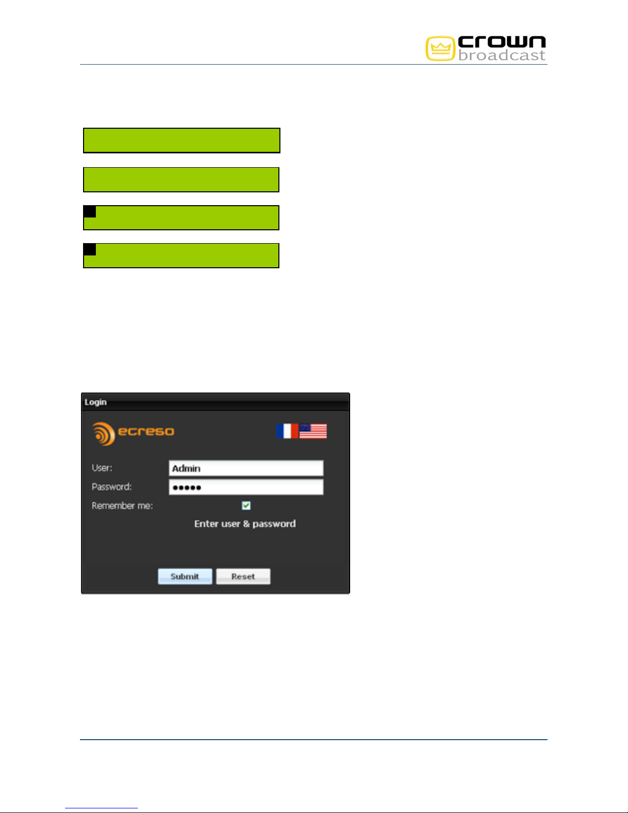
4.4.2. Connecting to the web interface
Now the transmitter is set. Connect it to the network.
Open a web browser (Google Chrome, Mozilla Firefox …) and enter in the address bar the transmitter’s
IP address such as it was set above.
Select the language if necessary.
From the main screen, press the "Enter” key to display
menus and then the “+” key until you see the Network
menu.
Once you see this screen, press “Enter”.
The IP address screen is displayed. Press “Enter” to
switch to edit mode. Use the “+” and “–” keys to adjust
values and the “Enter” key to confirm.
Press the “+” key to display the Netmask and modify it if
needed. Press the “Enter” key to confirm.
Enter the user name and password (default: Admin / admin).
You can now access the web interface.
Crown Broadcast, a division of International Radio & Electronics Corporation 25166 Leer Drive, Elkhart, Indiana, 46514-5425 USA
Page 29
Ph +1 (574) 262 8900
Crown Broadcast FME 350W to 2000W User Manual– 05/2013
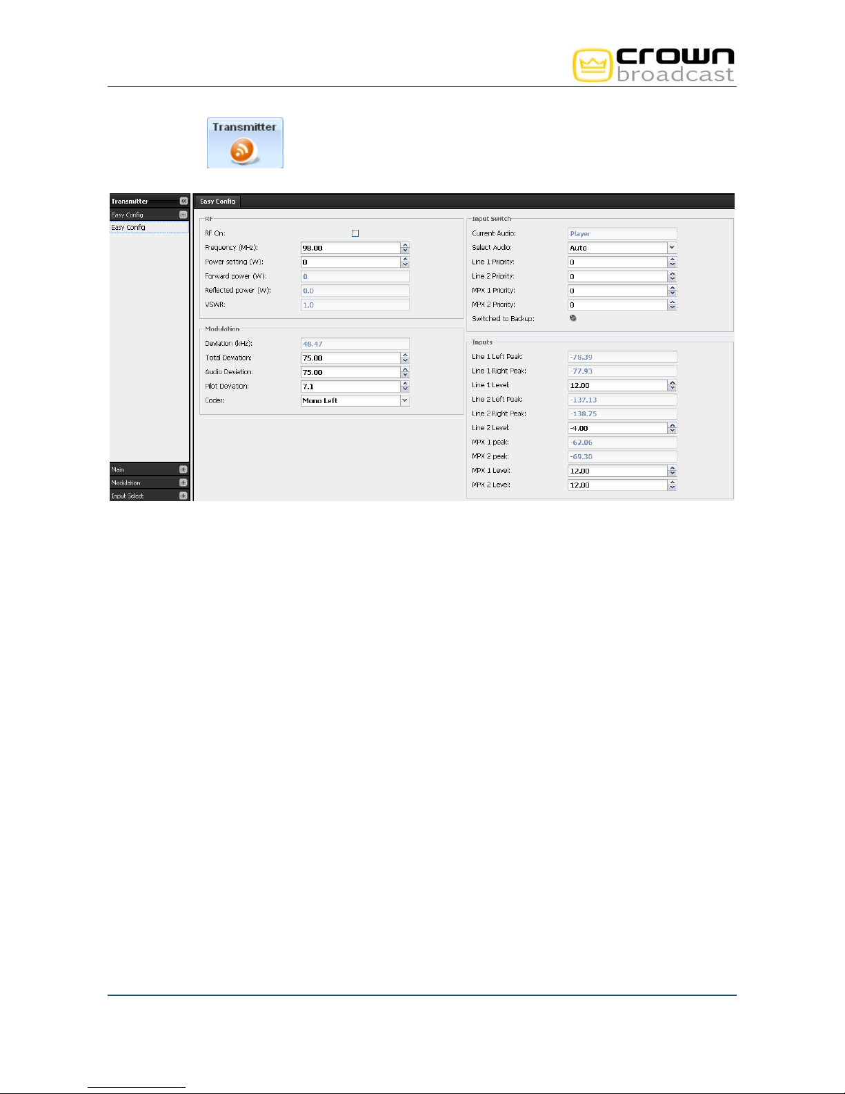
4.4.3. Configuring the transmitter
Click the button
in the tool bar to access the transmitter configuration and display the ‘Easy
Config’ page.
Basic configuration can be managed on this single page:
Power, frequency and RF on
Input priority setting
MPX configuration
Input configuration
Default transmitter pre-accentuation is 50 µs. Depending on your country, you might need to switch it to 75
µs (in the United States, for instance). The pre-accentuation parameter is available in the Input Source
section.
4.4.4. Getting on air
1. Disable the RF using the front panel RF button.
2. Make sure the RF indicator LED is off.
3. Disconnect the load and connect the antenna to the transmitter RF output.
4. Enable the RF again using the front panel RF button.
Crown Broadcast, a division of International Radio & Electronics Corporation 25166 Leer Drive, Elkhart, Indiana, 46514-5425 USA
Page 30
Ph +1 (574) 262 8900
 Loading...