

Crown FM600 User Manual
FM600 Broadcast Transmitter
User's Manual
©2008 Crown Broadcast, a division of
International Radio and Electronics Corporation
25166 Leer Drive, Elkhart, Indiana, 46514-5425 U.S.A. (574) 262-8900

Revision Control
Revision Print Date
Initial Release March 2007
Revision A January 2008
Important Notices
©2008, Crown Broadcast, a division of International Radio and Electronics Corporation.
Portions of this document were originally copyrighted by Michael P. Axman in 1994.
All rights reserved. No part of this publication may be reproduced, transmitted, transcribed,
stored in a retrieval system, or translated into any language in any form by any means without
the written permission of International Radio and Electronics, Inc.
Printed in U.S.A.
Crown Broadcast attempts to provide information that is accurate, complete, and useful.
Should you find inadequacies in the text, please send your comments to the following address:
International Radio and Electronics Corporation
P.O. Box 2000
Elkhart, Indiana, 46515-2000 U.S.A.
ii

Contents
Section 1– Getting Acquainted 1-1
1.1 Your Transmitter 1-2
1.2 Applications and Options 1-3
1.2.1 Stand Alone 1-4
1.2.2 Backup 1-4
1.2.3 Exciter 1-4
1.2.4 Translator 1-5
1.2.5 Satellator 1-6
1.3 Transmitter/Exciter Specifications 1-7
1.4 Receiver Specifications 1-9
1.5 Safety Considerations 1-9
1.5.1 Dangers 1-9
1.5.2 Warnings 1-9
1.5.3 Cautions 1-9
Section 2– Installation 2-1
2.1 Operating Environment 2-2
2.2 Power Connections 2-2
2.2.1 AC Line Voltage Setting 2-2
2.2.2 Fuses 2-3
2.3 Frequency (Channel) Selection 2-4
2.3.1 Modulation Compensator 2-6
2.4 Receiver Frequency Selection 2-7
2.5 RF Connections 2-11
2.6 Audio Input Connections 2-12
2.7 SCA Input Connections 2-13
2.8 Composite Input Connection 2-13
2.9 Audio Monitor Connections 2-14
2.10 Pre-emphasis Selection 2-14
2.11 Program Input Fault Time-out 2-15
2.12 Remote I/O Connector 2-15
iii

Section 3-Operation 3-1
3.1 Initial Power-up Procedures 3-2
3.2 Power Switches 3-4
3.2.1 Power Switch 3-4
3.2.2 Carrier Switch 3-4
3.3 Front Panel Bar-Dot Displays 3-5
3.3.1 Audio Processor Input 3-5
3.3.2 Highband and Wideband Display 3-5
3.3.3 Modulation Display 3-5
3.4 Input Gain Switches 3-6
3.5 Processing Control 3-6
3.6 Stereo-Mono Switch 3-6
3.7 RF Output Control 3-7
3.8 Digital Multimeter 3-7
3.9 Fault Indicators 3-8
Section 4-Principals of Operation 4-1
4.1 Part Numbering 4-2
4.2 Audio Processor/Stereo Generator Circuit Board 4-3
4.2.1 Audio Processor Section 4-3
4.2.2 Stereo Generator Section 4-4
4.3 RF Exciter Circuit 4-6
4.4 Metering Circuit 4-7
4.5 Motherboard 4-8
4.6 Display Circuit Board 4-10
4.7 Driver Switch logic Board 4-11
4.8 RF Driver 4-13
4.9 RF Amplifier 4.14
4.10 Chassis 4-15
4.11 RF Output Filter & Reflectometer 4-15
4.12 Receiver Circuit Board Option 4-16
iv

Section 5-Adjustments and Tests 5-1
5.1 Audio Processor Adjustments 5-2
5.1.1 Pre-Emphasis Selection 5-2
5.1.2 Pre-Emphasis Adjustment 5-2
5.2 Stereo Generator Adjustments 5-2
5.2.1 Separation 5-2
5.2.2 Composite Output 5-3
Using a Modulation Monitor 5-3
5.2.3 19kHz Level 5-3
5.2.4 19kHz Phase 5-3
5.3 Frequency Synthesizer Adjustments 5-3
5.3.1 Frequency (Channel) Selection 5-3
5.3.2 Modulation Compensator 5-4
5.3.3 Frequency Measurement and Adjustment 5-4
5.3.4 FSK Frequency Offset Control 5-4
5.4 Metering Board Adjustments 5-4
5.4.1 Power Calibrate 5-4
5.4.2 Power Set 5-4
5.4.3 SWR Calibrate 5-5
5.4.4 PA Current Limit 5-5
5.5 Motherboard Configuration 5-5
5.6 Display Modulation Calibration 5-5
5.7 Driver Switch Logic Adjustment 5-6
5.8 Bias Set (RF Power Amplifier) 5-6
5.9 Performance Verification 5-7
5.9.1 Audio Proof of Performance Measurements 5-7
5.9.2 De-Emphasis Input Network 5-7
5.10 Carrier Frequency 5-8
5.11 Output Power 5-8
5.12 RF Bandwidth and RF Harmonics 5-8
5.13 Pilot Frequency 5-8
5.14 Audio Frequency Response 5-8
5.15 Audio Distortion 5-9
5.16 Modulation Percentage 5-9
5.17 FM and AM Noise 5-9
5.18 Stereo Separation 5-9
5.19 Crosstalk 5-9
5.19.1 Main Channel Into Sub 5-9
5.19.2 Sub Channel Into Main 5-9
5.20 38kHz Subcarrier Suppression 5-10
5.21 Additional Checks 5-10
v

Section 6-Reference Drawings 6-1
6.1 Views 6-2
6.2 Board Layouts and Schematics 6-4
Section 7-Service and Support 7-1
7.1 Service 7-2
7.2 24-Hour Support 7-2
Transmitter Output Efficiency Appendix-1
Glossary G-1
Index Index-1
vi
Section 1—Getting Acquainted
This section provides a general description of the FM600 transmitter and
introduces you to safety conventions used within this document. Review
this material before installing or operating the transmitter.
1-1 Getting Acquainted
1.1 Your Transmitter
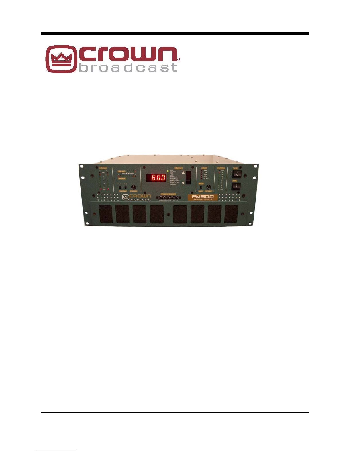
The FM600 is a member of a family of FM stereo broadcast transmitters. Crown transmitters
are known for their integration, ease-of-use, and reliability.
The integration is most apparent in the standard transmitter configuration which incorporates
audio processing, stereo generation, and RF amplification without compromised signal quality.
A single Crown transmitter can replace several pieces of equipment in a traditional system.
Ease-of-use is apparent in the user-friendly front panel interface and in the installation
procedure. Simply select your operating frequency (using 5 external switches), add an audio
source, attach an antenna, and connect AC power and you're ready to broadcast. Of course,
the FM series of transmitters also feature more sophisticated inputs and monitoring
connections if needed.
Reliability is a Crown tradition. The first Crown transmitters were designed for rigors of
worldwide and potentially portable use. The modular design, quality components, engineering
approach, and high production standards ensure stable performance.
Remote control and metering of the transmitter are made possible through a built-in I/O connector. For more direct monitoring, the front panel includes a digital multimeter display and
status indicators. Automatic control circuitry provides protection for high VSWR as well as high
current, voltage, and temperature conditions.
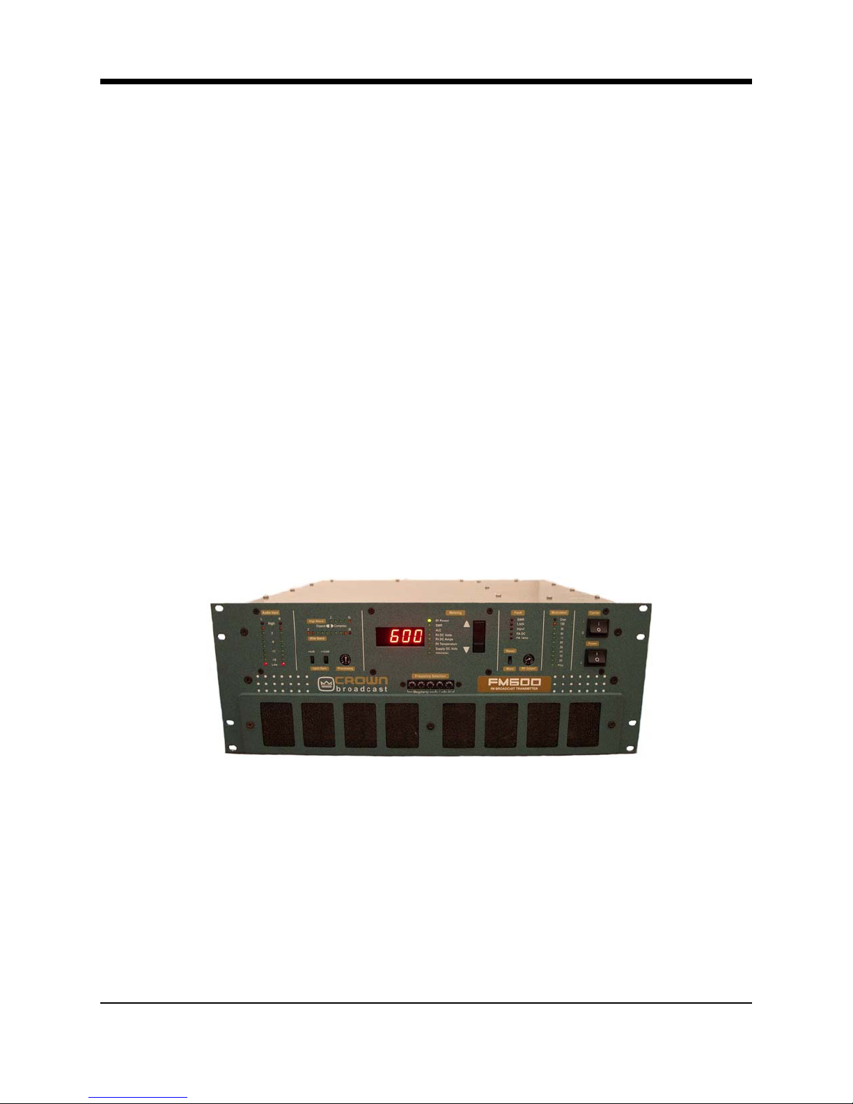
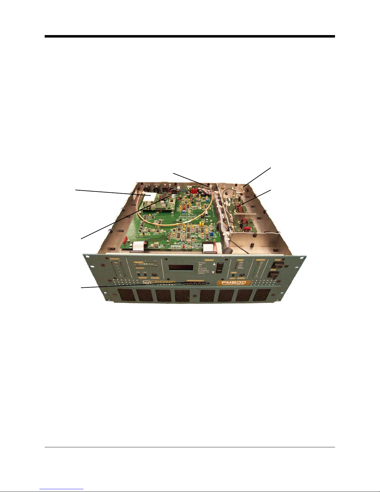
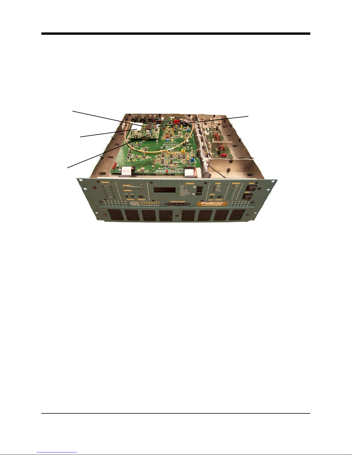
Illustration 1-1 FM600 Stereo Broadcast Transmitter
1-2 FM600 Manual
1.2 Applications and Options
Crown transmitters are designed for versatility in applications. They have been used as
stand-alone and backup transmitters and in booster, translator, satellator, and nearcast
applications. The following discussion describes these applications further.
Model numbers describe the configuration of the product (which has to do with its intended
purpose) and the RF output power which you can expect.
The number portion of each name represents the maximum RF output power. The FM600,
for example, can generate up to 600 watts of RF output power.
Suffix letters describe the configuration. The FM600T, for example, is the standard or
transmitter configuration. Except where specified, this document describes the transmitter
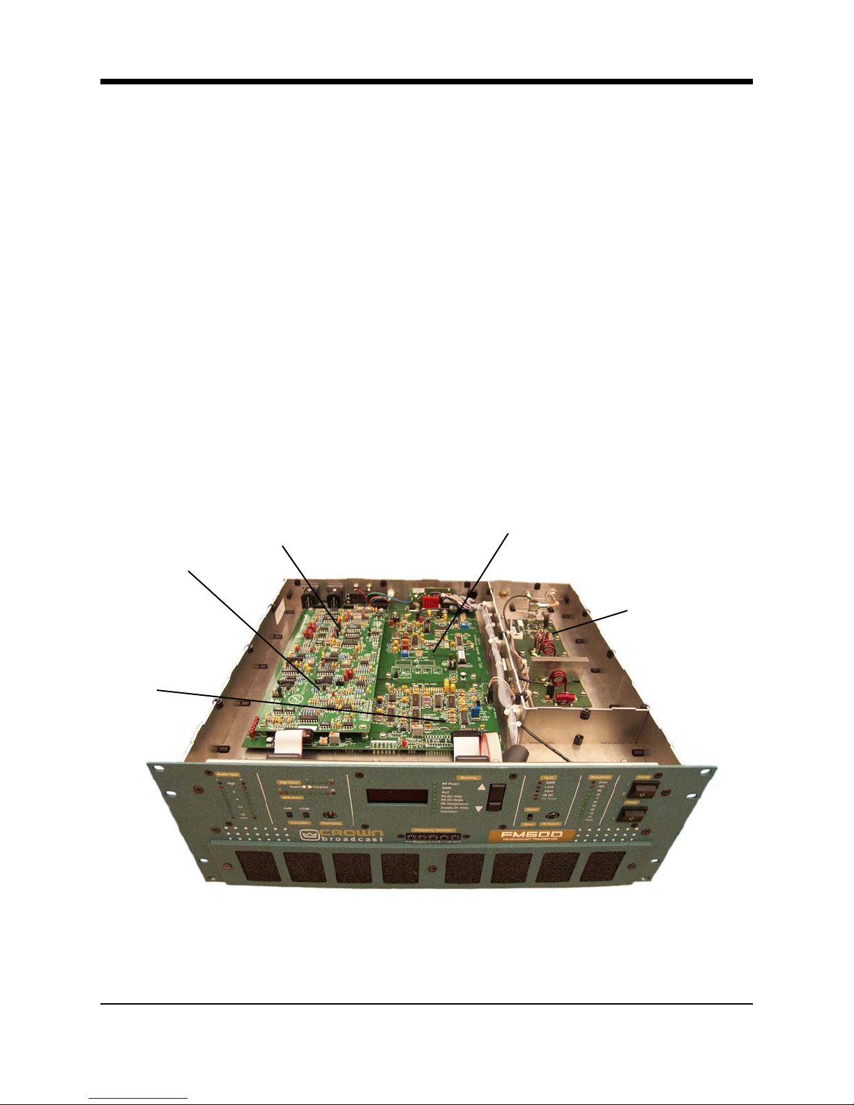
configuration. In this configuration, the product includes the following components
(functions):
• Audio Processor/Stereo Generator
• RF Exciter
• Metering
• Low-Pass filter
Audio
Processor
Circuit
Metering
Circuit
Stereo
Generator
Circuit
RF Exciter Circuit
RF Low Pass filter
Illustration 1–2 Standard (Transmitter) Configuration
1-3 Getting Acquainted

1.2.1 Stand-Alone
In the standard configuration, the FM600 is an ideal stand-alone transmitter. When you add
an audio source (monaural, L/R stereo, or composite signal), an antenna, and AC power,
the transmitter becomes a complete FM stereo broadcast station, capable of serving a
community.
As stand-alone transmitters, Crown units often replace multiple pieces of equipment in a
traditional setup (exciter, audio processor, RF amplifier).
1.2.2 Backup
In the standard configuration, Crown transmitters are also used in backup applications.
Should your primary transmitter become disabled, you can continue to broadcast while
repairs take place. In addition, the FM transmitters can replace disabled portions of your
existing system including the exciter, audio processor, or amplifier. Transfer switches on
each side of the existing and backup transmitters make the change-over possible with
minimal downtime.
1.2.3 Exciter
In addition to the standard configuration, the FM600 is available in optional configurations to
meet a variety of needs.
An "E" suffix, as in the FM600E, for example, represents an exciter-only configuration. In
this configuration, the audio processor and stereo generator boards are replaced with circuitry to bypass their function. The exciter configurations are the least expensive way to get
Crown quality components into your transmission system.
You might consider the Crown exciter when other portions of your system are performing
satisfactorily and you want to maximize your investment in present equipment.
1-4 FM600 Users Manual
1.2.4 Translator
A receiver configuration (FM600R, for example) replaces the audio processor/stereo generator
board with a receiver module. This added feature makes the FM600 ideal for translator service
in terrestrial-fed networks. These networks represent a popular and effective way to increase
your broadcasting coverage. Translators, acting as repeater emitters, are necessary links in
this chain of events.
Traditionally, network engineers have relied on multiple steps and multiple pieces of equipment
to accomplish the task. Others have integrated the translator function (receiver and exciter) to
feed an amplifier. Crown, on the other hand, starts with an integrated transmitter and adds a
solid-state Receiver Module to form the ideal translator.
Receiver
Module
(Option)
Frequency
Selection
(Receive)
Frequency
Selection
Transmit
RF Input
(Receive Antenna)
RF Output
RF Low
Pass Filter
Illustration 1–3 Crown's Integrated Translator
This option enables RF input and RF output on any of Crown’s FM series of transmitters. In
addition, the module supplies a composite output to the RF exciter portion of the transmitter.
From here, the signal is brought to full power by the built-in power amplifier for retransmission.
The Receiver Module has been specifically designed to handle SCA channel output up to 100
kHz for audio and high-speed data.
FSK ID programming is built-in to ensure compliance with FCC regulations regarding the on-air
identification of translators. Simply specify the call sign of the repeater station when ordering.
Should you need to change the location of the translator, replacement FSK chips are available.
The Receiver Module option should be ordered at the time of initial transmitter purchase. However, an option kit is available for field converting existing Crown units.
In the translator configuration there are differences in the function of the front panel. See Section 3 for a description.
1-5 Getting Acquainted
1.2.5 Satellator
One additional option is available for all configurations—an FSK Identifier (FSK IDer). This
added feature enables the FM600 to transmit its call sign or operating frequency in a Morse
code style. This option is intended for use in satellite-fed networks. Transmitters equipped in
this fashion are often known as "satellators."
Connect the transmitter to your satellite receiver and the pre-programmed FSK IDer does the
rest—shifting the frequency to comply with FCC requirements and in a manner that is unnoticeable to the listener. The FSK IDer module should be ordered at the time you order your
transmitter, but is available separately (factory programmed for your installation).
FSK Ider
Illustration 1–4 Transmitter with FSK IDer Option
Add the FSK IDer option to the exciter configuration for the most economical satellator. (A
composite input signal is required.)
1-6 FM600 User’s Manual

1.3 Transmitter/Exciter Specifications
Frequency Range 87.9 MHz–107.9 MHz (76 MHz–90 MHz
optionally available)
RF Power Output (VSWR 1.7:1 or better)
FM600 Up to 660 watts output
RF Output Impedance 50 Ohms
Frequency Stability Meets FCC specifications from 0-50
degrees C
Audio Input Impedance 50k Ω bridging, balanced, or 600 Ω
Audio Input Level Selectable for –10 dBm to +10 dBm for
75 kHz deviation at 400 Hz
Pre-emphasis Selectable for 25, 50, or 75 µsec; or flat
Audio Response Conforms to 75 µsec pre-emphasis
curve as follows:
Complete Transmitter ±0.30 dB (50 Hz–10 kHz)
±1.0 dB (10 kHz–15 kHz)
Exciter only ±0.25 dB (50 Hz–15 kHz)
Distortion (THD + Noise)
Complete Transmitter Less than 0.7% (at 15kHz)
Exciter only Less than 0.3% (50Hz-15kHz)
Stereo Separation
Complete Transmitter Better than –40dB (50Hz-15kHz)
Exciter only Better than –40dB (50Hz-15kHz)
Crosstalk Main into Sub, better than –40dB
Sub into Main, better than –40dB
Stereo Pilot 19 kHz ±2 Hz, 9% modulation
1-7 Getting Acquainted

Subcarrier Suppression 50dB below ±75 kHz deviation
FM S/N Ratio (FM noise)
Complete Transmitter Better than –60dB
Exciter only Better than –70dB
AM S/N Ratio Asynchronous and synchronous noise
better than FCC requirements
RF Bandwidth ±120 kHz, better than –35 dB
±240 kHz, better than –45 dB
RF Spurious Products Better than –71dB
Operating Environment Temperature (0
°C to 50°C)
Humidity (0 to 80% at 20°C)
9834 Feet
Maximum Altitude (3,000 Meters;
AC Power 120-240 volts* +/-10% 50/60Hz
Note: We set voltage and ampere requirements to assist you in designing your system. Depending on your operating frequency, actual requirements for maximum voltage and current
readings are 10–15% lower than stated.
Regulatory Type notified FCC parts 73 and 74
Meets FCC, DOC
Dimensions 32.38 x 59.69 x 62.23 centimeters
12.75 x 23.5 x 24.5 Inches
Weight 38 lbs
17.237 Kg
*200 volts AC input or greater, recommended for RF power output of 575W or greater. Voltage measured at the AC power input
connector to transmitter.
1-8 FM600 User’s Manual

1.4 Receiver Specifications
Monaural Sensitivity (demodulated, de-emphasized)
3.5 µ V for signal-to-noise > 50 dB
Stereo Sensitivity (19–kHz pilot frequency added)
31 µ V for signal-to-noise > 50 dB
Connector
Standard type N-Female, 50 Ω
Shipping Weight
1 lb
1.5 Safety Considerations
Crown Broadcast assumes the responsibility for providing you with a safe product and safety
guidelines during its use. “Safety” means protection to all individuals who install, operate, and
service the transmitter as well as protection of the transmitter itself. To promote safety, we use
standard hazard alert labeling on the product and in this manual. Follow the associated
guidelines to avoid potential hazard.
1.5.1 Dangers
DANGER represents the most severe hazard alert. Extreme bodily harm or death will occur if
DANGER guidelines are not followed.
1.5.2 Warnings
WARNING represents hazards which could result in severe injury or death.
1.5.3 Cautions
CAUTION indicates potential personal injury, or equipment or property damage if the associated guidelines are not followed. Particular cautions in this text also indicate unauthorized radio-frequency operation.
Illustration 1–5 Sample Hazard Alert
1-9 Getting Acquainted

Notes
1-10 FM600 User’s Manual
Section 2—Installation
This section provides important guidelines for installing your transmitter.
Review this information carefully for proper installation.
2-1 Installation
2.1 Operating Environment
You can install the FM transmitter in a standard component rack or on a suitable surface
such as a bench or desk. In any case, the area should be as clean and well ventilated as
possible. Always allow for at least 2 cm of clearance under the unit for ventilation. If you
set the transmitter on a flat surface, install spacers on the bottom cover plate. If you install
the transmitter in a rack, provide adequate clearance above and below. Do not locate the
transmitter directly above a hot piece of equipment.
2.2 Power Connections
The FM600 can operate on any voltage between 120 and 240 volts AC (50 or 60 Hz; single
phase).
2.2.1 AC Line Voltage Setting
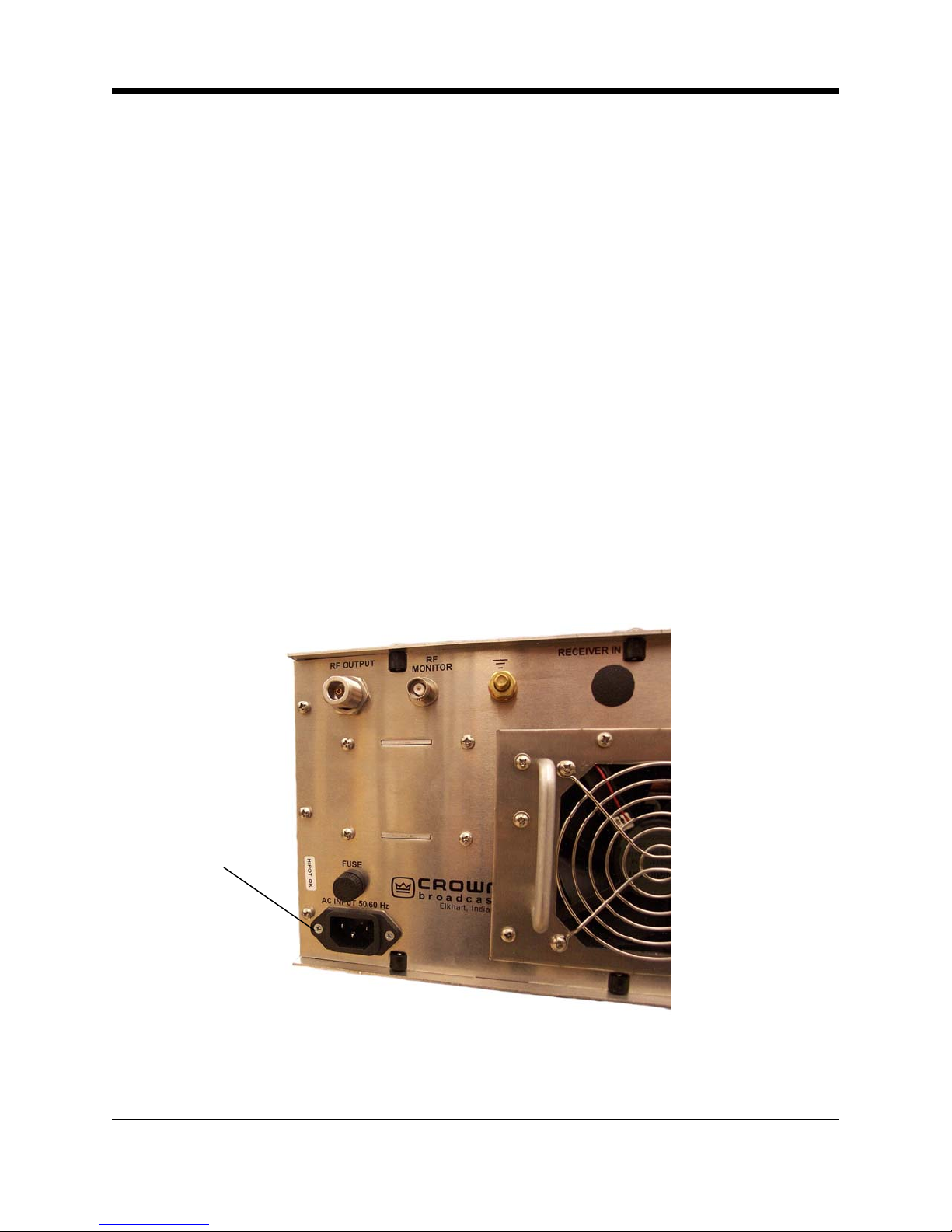
Voltage selection is automatic; configuration is not necessary.
AC Input Power
Connection
Illustration 2–2 AC Input Power Connection
2-2 FM600 User’s Manual
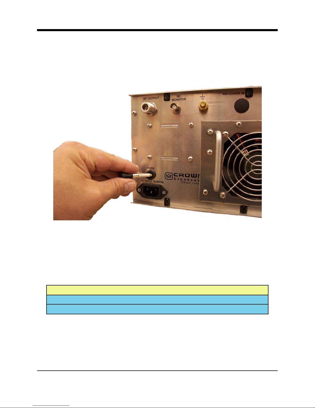
2.2.2 Fuses
The fuse holder is located on the back panel just above the power connection.
Illustration 2–3 Fuse Holder
For 120 to 200 VAC operation, use the fuse installed at the factory. For 200 to 240 VAC operation, use the slow-blow fuse located in a hardware kit within the transmitter packaging. Consult
the following table:
AC Input Voltage Fuse Rating
120-200 VAC 12 Ampere
200-240 VAC 6 Ampere
Illustration 2–4 Fuse Reference Table
2-3 Installation
2.3 Frequency (Channel) Selection
Your transmitter is capable of operating between 87.9 and 107.9 MHz in the FM band. The
transmitter can also operate between 76 and 90 MHz by shorting pins 9 and 10 of J20 on the
motherboard. See Illustration 2-6.
To adjust the operating frequency, follow these steps:
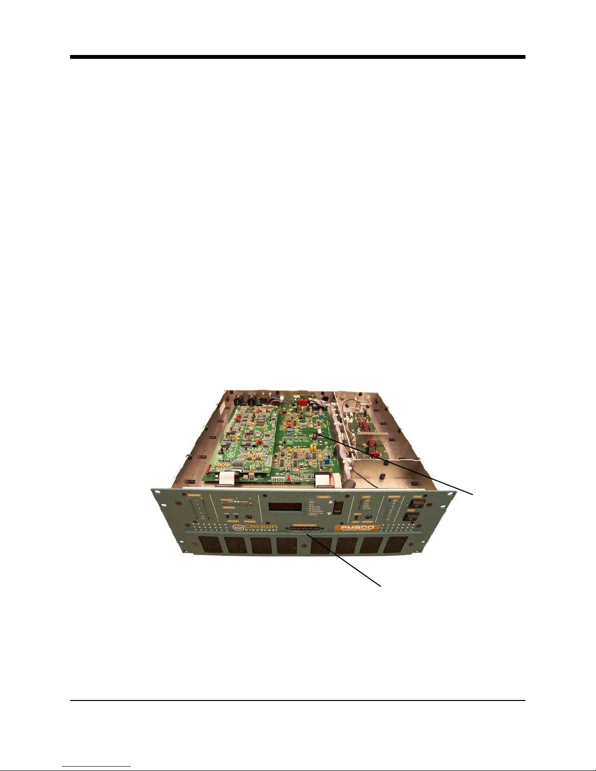
1. Locate the frequency selector switches on the front panel which will be used to change the
setting. See Illustrations 2–6 and 2–7.
2. Use small flat blade screwdriver or another suitable device to rotate the switches to the desired setting. (The selected number will appear directly above the white indicator dot on
each switch.) See examples of selected frequencies in the illustration below.
3. To change the operating band from 87.9-107.9MHz to 76-90MHz or vice versa, or to adjust
the modulation compensation pot, remove the top cover to gain access to these features.
See Illustrations 2-6 and 2-10.
2-4 FM600 User’s Manual
Frequency Selector Switches
Illustration 2–6 Top Cover Removed
J20
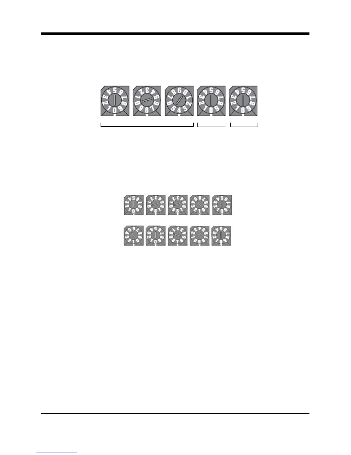
2.3 Frequency (Channel) Selection, continued
Megahertz .1 .01
Illustration 2–7 Transmitter Front Panel (Frequency Selector Switches)
= 88.10 MHz
= 107.90 MHz
Illustration 2–8 Two Sample Frequency Selections
2-5 Installation
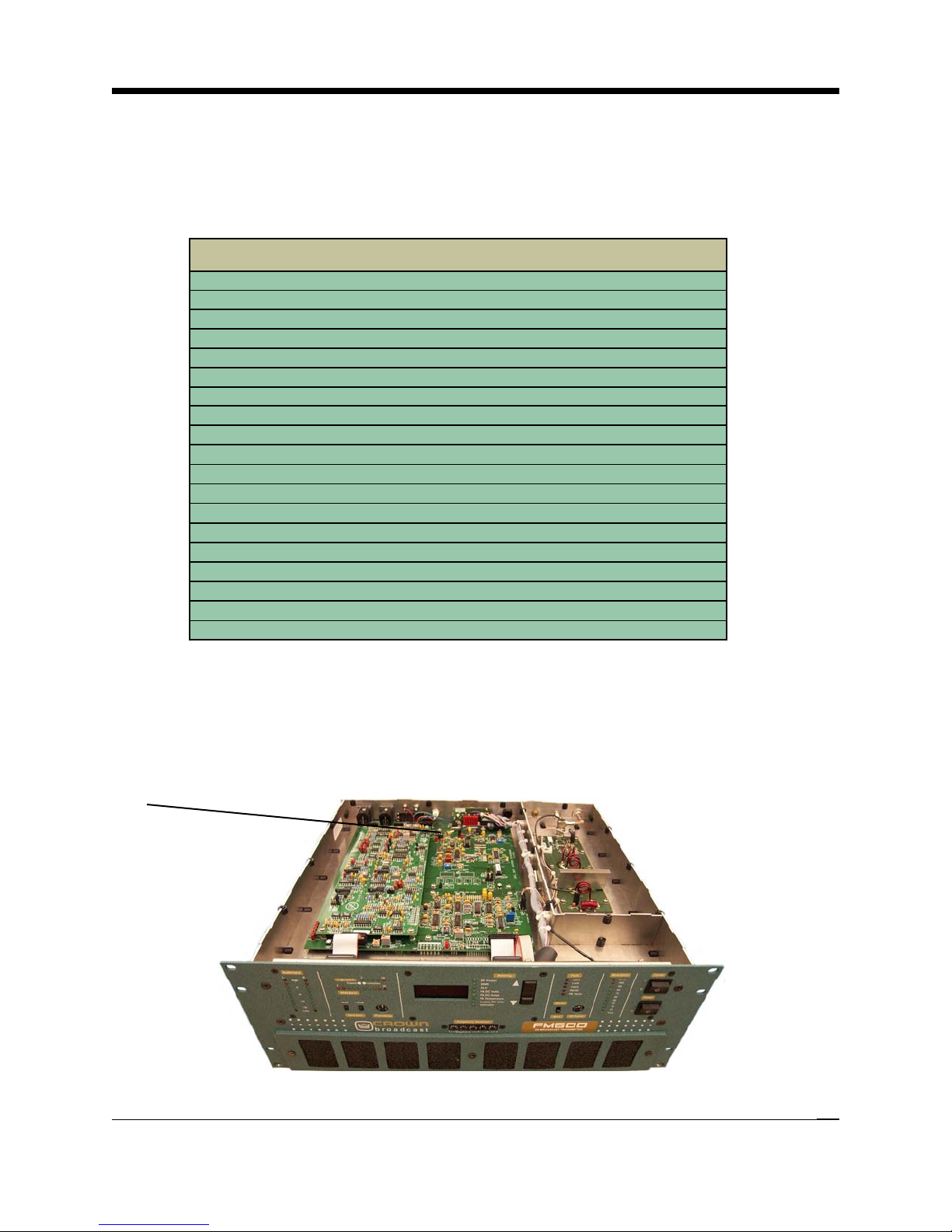
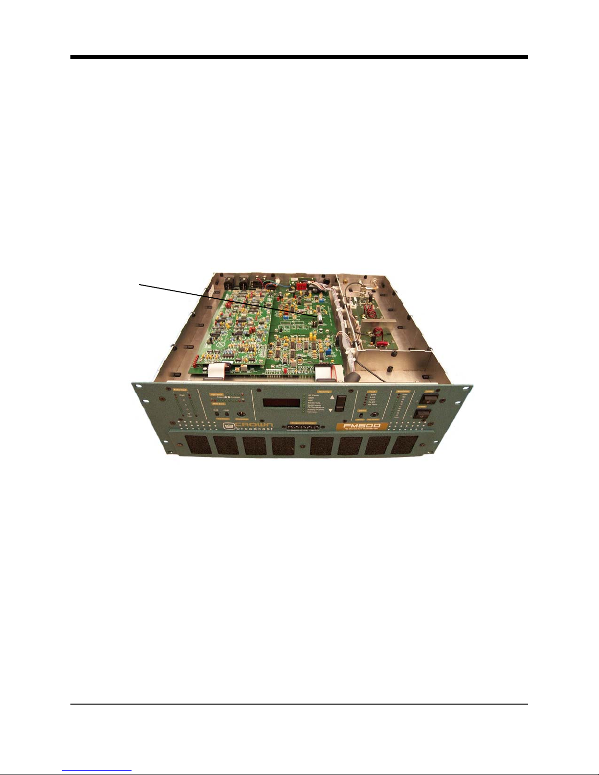
2.3.1 Modulation Compensator
The Modulation trim-potentiometer (see Illustration 2–10) compensates for slight variations in
deviation sensitivity with frequency. Set the trim-pot dial according to the following graph:
Frequency of Operation (MHz) Modulation Compensation Pot Setting
108 0
106 10
104 15
102 25
100 35
98 40
97.1 45
96 55
94 60
92 70
90 75
88 80
86 80
84 80
82.4 70
82 65
80 55
78 30
76 0
Illustration 2–9 Modulation Compensator Settings
These compensator settings are approximate. Each mark on the potentiometer represents
about 1.8% modulation compensation.
Modulation
Compensator
Pot
Illustration 2–10 Modulation Compensator Pot
2-6 FM600 User’s Manual
2.4 Receiver Frequency Selection
If you have a transmitter equipped with the receiver option, you will need to set the receiving or
incoming frequency.
1. With the top cover removed, locate the receiver module and the two switches (labeled SW1
and SW2).
J1
Receiver
Module
J2
Frequency
Switches
Illustration 2–11 Receiver Module Switches
2. Use the adjacent chart to set the switches for the desired incoming frequency.
3. For frequencies in the Japan FM band, short pins 7&8 on J1 on the receiver card.
4. For 75us pre-emphasis short pins 3&4 and 5&6 on J2 of the Receiver card.
5. For 50us pre-emphasis short pins 1&2 and 7&8 on J2 of the Receiver card.
6. After setting the frequency, replace the top cover and screws.
2-7 Installation

Freq. 74-90
MHz
Freq. 88-108
MHz
SW1 SW2 Freq. 74-90
MHz
Freq. 88-108
MHz
SW1 SW2
74.9 87.9 0 0 78.9 91.9 1 4
75.0 88.0 8 0 79.0 92.0 9 4
75.1 88.1 0 1 79.1 92.1 1 5
75.2 88.2 8 1 79.2 92.2 9 5
75.3 88.3 0 2 79.3 92.3 1 6
75.4 88.4 8 2 79.4 92.4 9 6
75.5 88.5 0 3 79.5 92.5 1 7
75.6 88.6 8 3 79.6 92.6 9 7
75.7 88.7 0 4 79.7 92.7 1 8
75.8 88.8 8 4 79.8 92.8 9 8
75.9 88.9 0 5 79.9 92.9 1 9
76.0 89.0 8 5 80.0 93.0 9 9
76.1 89.1 0 6 80.1 93.1 1 A
76.2 89.2 8 6 80.2 93.2 9 A
76.3 89.3 0 7 80.3 93.3 1 B
76.4 89.4 8 7 80.4 93.4 9 B
76.5 89.5 0 8 80.5 93.5 1 C
76.6 89.6 8 8 80.6 93.6 9 C
76.7 89.7 0 9 80.7 93.7 1 D
76.8 89.8 8 9 80.8 93.8 9 D
76.9 89.9 0 A 80.9 93.9 1 E
77.0 90.0 8 A 81.0 94.0 9 E
77.1 90.1 0 B 81.1 94.1 1 F
77.2 90.2 8 B 81.2 94.2 9 F
77.3 90.3 0 C 81.3 94.3 2 0
77.4 90.4 8 C 81.4 94.4 A 0
77.5 90.5 0 D 81.5 94.5 2 1
77.6 90.6 8 D 81.6 94.6 A 1
77.7 90.7 0 E 81.7 94.7 2 2
77.8 90.8 8 E 81.8 94.8 A 2
77.9 90.9 0 F 81.9 94.9 2 3
78.0 91.0 8 F 82.0 95.0 A 3
78.1 91.1 1 0 82.1 95.1 2 4
78.2 91.2 9 0 82.2 95.2 A 4
78.3 91.3 1 1 82.3 95.3 2 5
78.4 91.4 9 1 82.4 95.4 A 5
78.5 91.5 1 2 82.5 95.5 2 6
78.6 91.6 9 2 82.6 95.6 A 6
78.7 91.7 1 3 82.7 95.7 2 7
78.8 91.8 9 3 82.8 95.8 A 7
Illustration 2–12-1 Receiver Frequency Selection
2-8 FM600 User’s Manual
(Continued on next page)

Freq. 74-90
MHz
Freq. 88-108
MHz
SW1 SW2 Freq. 74-90
MHz
Freq. 88-108
MHz
SW1 SW2
82.9 95.9 2 8 86.6 99.6 B A
83.0 96.0 A 8 86.7 99.7 3 B
83.1 96.1 2 9 86.8 99.8 B B
83.2 96.2 A 9 86.9 99.9 3 C
83.3 96.3 2 A 87.0 100.0 B C
83.4 96.4 A A 87.1 100.1 3 D
83.5 96.5 2 B 87.2 100.2 B D
83.6 96.6 A B 87.3 100.3 3 E
83.7 96.7 2 C 87.4 100.4 B E
83.8 96.8 A C 87.5 100.5 3 F
83.9 96.9 2 D 87.6 100.6 B F
84.0 97.0 A D 87.7 100.7 4 0
84.1 97.1 2 E 87.8 100.8 C 0
84.2 97.2 A E 87.9 100.9 4 1
84.3 97.3 2 F 88.0 101.0 C 1
84.4 97.4 A F 88.1 101.1 4 2
84.5 97.5 3 0 88.2 101.2 C 2
84.6 97.6 B 0 88.3 101.3 4 3
84.7 97.7 3 1 88.4 101.4 C 3
84.8 97.8 B 1 88.5 101.5 4 4
84.9 97.9 3 2 88.6 101.6 C 4
85.0 98.0 B 2 88.7 101.7 4 5
85.1 98.1 3 3 88.8 101.8 C 5
85.2 98.2 B 3 88.9 101.9 4 6
85.3 98.3 3 4 89.0 102.0 C 6
85.4 98.4 B 4 89.1 102.1 4 7
85.5 98.5 3 5 89.2 102.2 C 7
85.6 98.6 B 5 89.3 102.3 4 8
85.7 98.7 3 6 89.4 102.4 C 8
85.8 98.8 B 6 89.5 102.5 4 9
85.9 98.9 3 7 89.6 102.6 C 9
86.0 99.0 B 7 89.7 102.7 4 A
86.1 99.1 3 8 89.8 102.8 C A
86.2 99.2 B 8 89.9 102.9 4 B
86.3 99.3 3 9 90.0 103.0 C B
86.4 99.4 B 9 X 103.1 4 C
86.5 99.5 3 A X 103.2 C C
Illustration 2–12-2 Receiver Frequency Selection
(Continued on next page)
2-9 Installation

Freq. 74-90
MHz
Freq. 88-108
MHz
SW1 SW2 Freq. 74-90
MHz
Freq. 88-108
MHz
SW1 SW2
X 103.3 4 D X 107.0 D F
X 103.4 C D X 107.1 6 0
X 103.5 4 E X 107.2 E 0
X 103.6 C E X 107.3 6 1
X 103.7 4 F X 107.4 E 1
X 103.8 C F X 107.5 6 2
X 103.9 5 0 X 107.6 E 2
X 104.0 D 0 X 107.7 6 3
X 104.1 5 1 X 107.8 E 3
X 104.2 D 1 X 107.9 6 4
X 104.3 5 2 X 108.0 E 4
X 104.4 D 2
X 104.5 5 3
X 104.6 D 3
X 104.7 5 4
X 104.8 D 4
X 104.9 5 5
X 105.0 D 5
X 105.1 5 6
X 105.2 D 6
X 105.3 5 7
X 105.4 D 7
X 105.5 5 8
X 105.6 D 8
X 105.7 5 9
X 105.8 D 9
X 105.9 5 A
X 106.0 D A
X 106.1 5 B
X 106.2 D B
X 106.3 5 C
X 106.4 D C
X 106.5 5 D
X 106.6 D D
X 106.7 5 E
X 106.8 D E
X 106.9 5 F
Illustration 2–12-3 Receiver Frequency Selection
2-10 FM600 User’s Manual
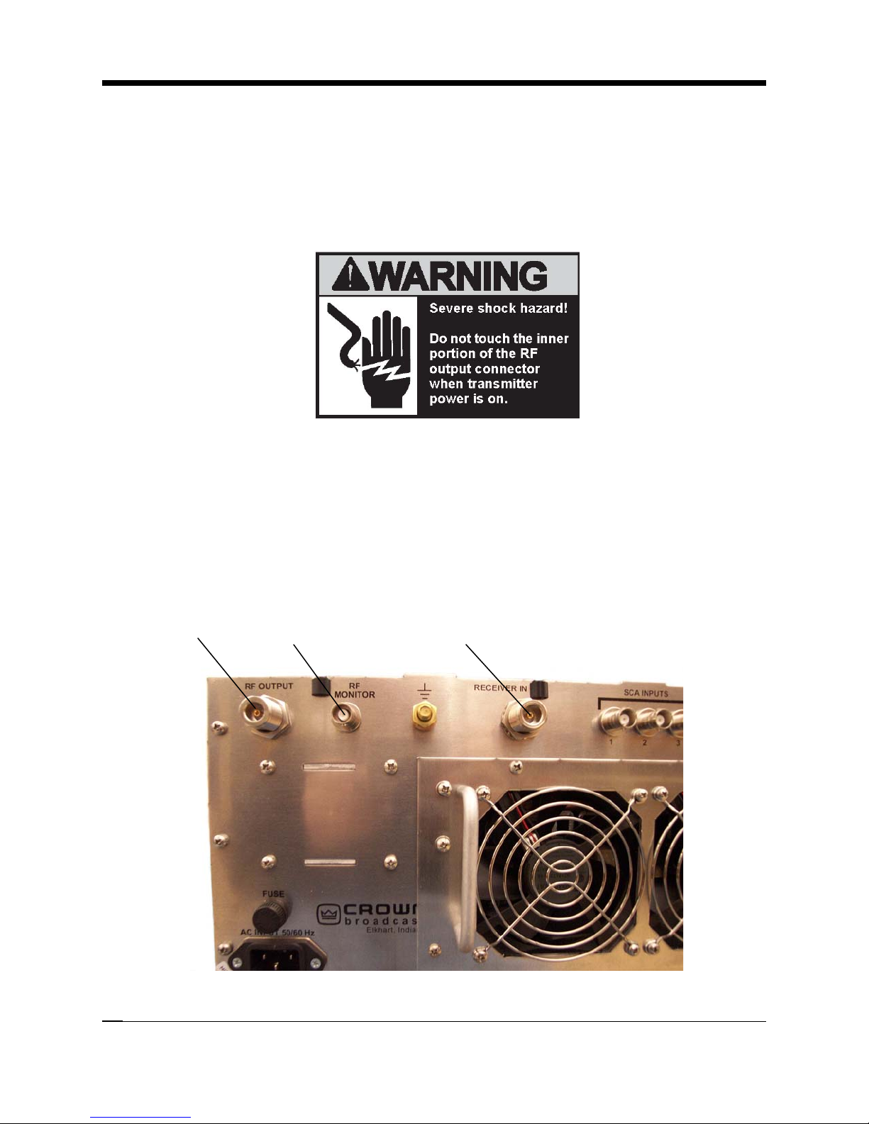
2.5 RF Connections
Connect the RF load, an antenna or the input of an external power amplifier, to the type-N, RF
output connector on the rear panel. VSWR should be 1.5:1 or better.
The RF monitor is intended primarily for a modulation monitor connection. Information gained
through this connection can supplement that which is available on the transmitter front panel
displays.
If your transmitter is equipped with the receiver option, connect the incoming RF to the Receiver IN connector.
RF Output
Connector
RF Monitor
Connector
Receiver In
(Receiver Option Only)
Illustration 2–13 RF Connections
2-11 Installation
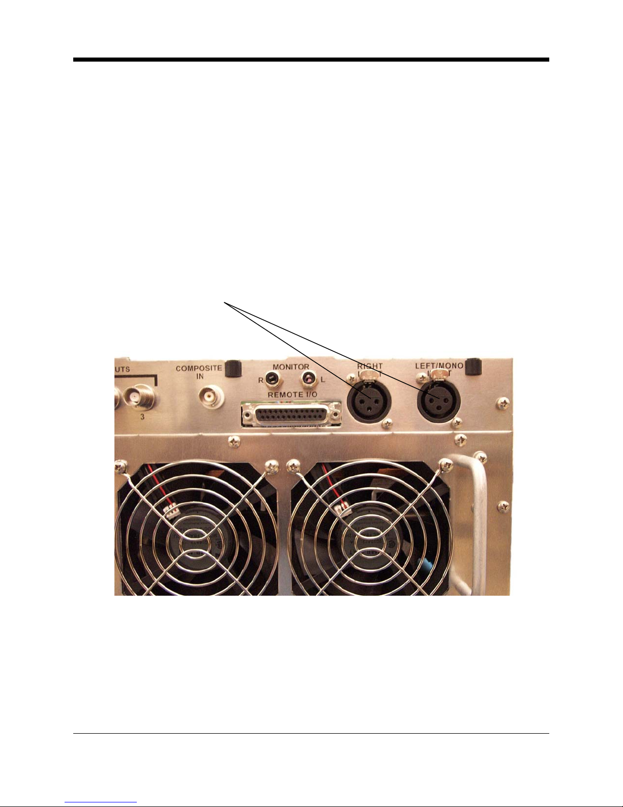
2.6 Audio Input Connections
Attach audio inputs to the Left and Right XLR connectors on the rear panel. (The Left channel
audio is used on Mono.) Pin 1 of the XLR connector goes to chassis ground. Pins 2 and 3
represent a balanced differential input with an impedance of about 50 kΩ . They may be
connected to balanced or unbalanced left and right program sources.
The audio input cables should be shielded pairs, whether the source is balanced or unbalanced. For an unbalanced program source, one line (preferably the one connecting to pin 3)
should be grounded to the shield at the source. Audio will then connect to the line going to pin
2.
Audio Inputs
(XLR)
Illustration 2–14 XLR Audio Input Connectors
By bringing the audio return line back to the program source, the balanced differential input of
the transmitter is used to best advantage to minimize noise. This practice is especially helpful
if the program lines are fairly long, but is a good practice for any distance.
If the program source requires a 600 Ω termination, see the motherboard configuration chart
on page 4-9 for the proper configuration of the jumpers.
2-12 FM600 User’s Manual
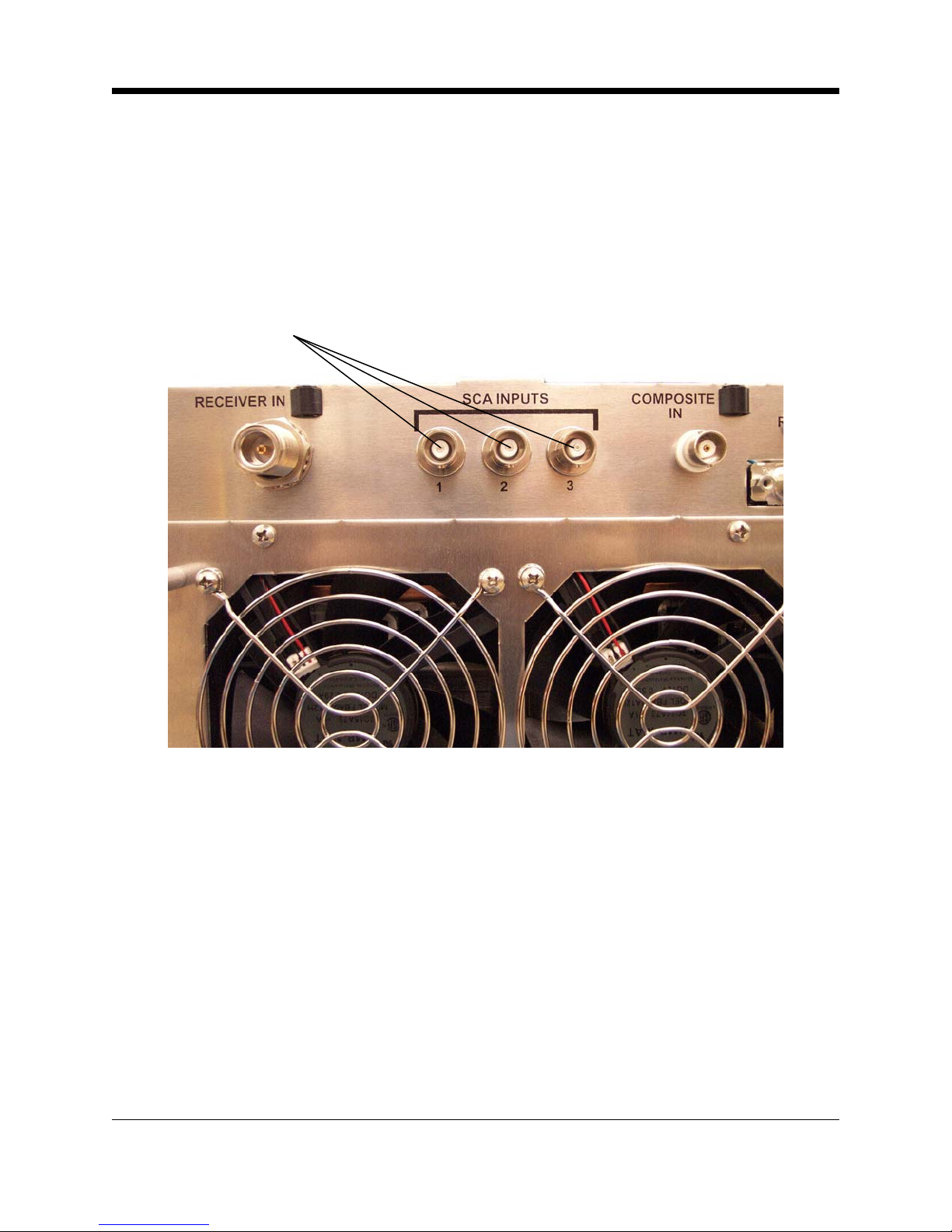
2.7 SCA Input Connections
You can connect external SCA generators to the SCA In connectors (BNC-type) on the rear
panel. The inputs are intended for the 60 kHz to 99 kHz range, but a lower frequency may be
used if the transmitter is operated in Mono mode. (The 23 to 53 kHz band is used for stereo
transmission.) For 7.5 kHz deviation (10% modulation), input of approximately 3.5–volts (peak
-to-peak) is required.
SCA Inputs
Illustration 2–15 SCA Input Connectors
2.8 Composite Input Connection
You may feed composite stereo (or mono audio) directly to the RF exciter bypassing the internal audio processor and stereo generator. To use the Crown transmitter as an RF Exciter only
("E" version or when using the "T" version with composite input), it is necessary to use the
Composite Input section of the transmitter. This will feed composite stereo (or mono audio)
directly to the RF exciter. In the "T" version, this will bypass the internal audio processor and
stereo generator.
Input sensitivity is approximately 3.5–volt P-P for 75 kHz deviation.
1. Enable the Composite Input by grounding pin 14 of the Remote I/O connector
(see Illustration 2–18).
2. Connect the composite signal using the Composite In BNC connector.
2-13 Installation
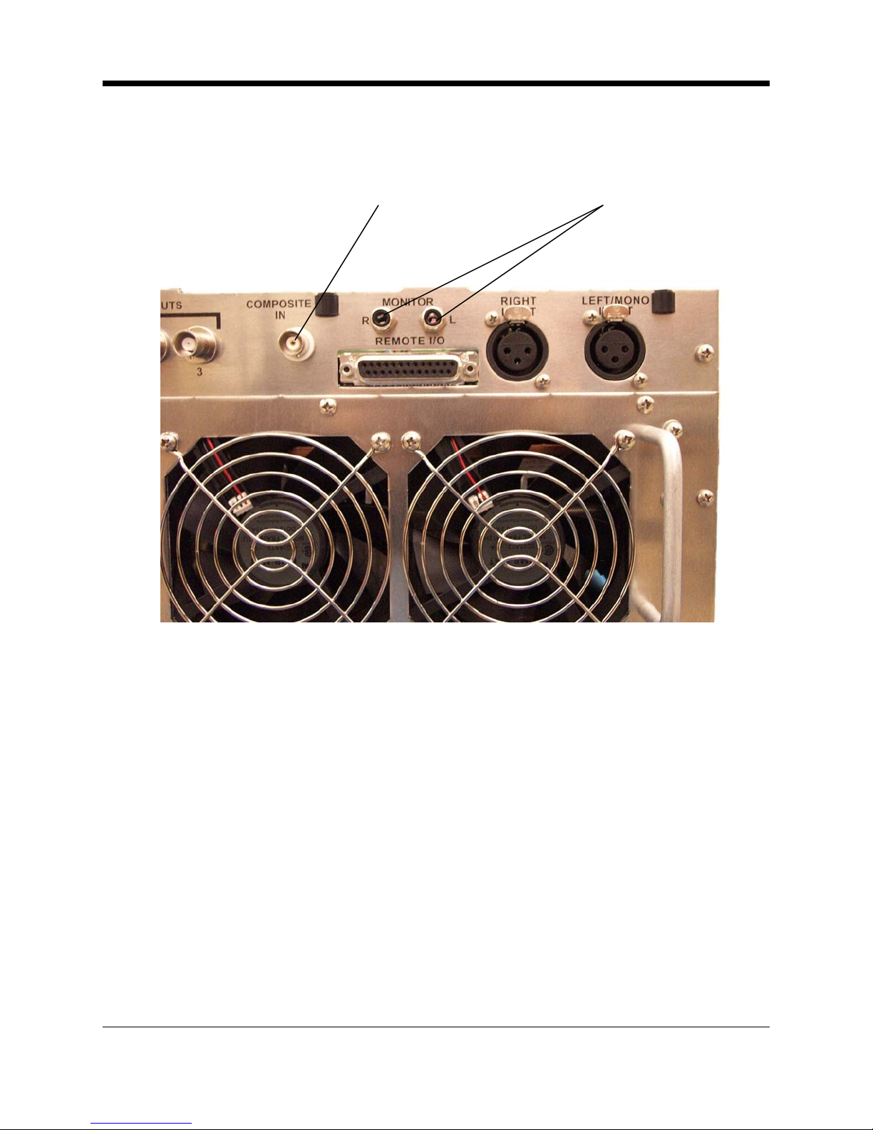
Composite IN
BNC Connector
Audio Monitor Jacks
Illustration 2–16 Composite In and Audio Monitor Connections
2.9 Audio Monitor Connections
Processed, de-emphasized samples of the left and right audio inputs to the stereo generator
are available at the Monitor jacks on the rear panel. The signals are suitable for feeding a studio monitor and for doing audio testing. De-emphasis is normally set for 75 µsec; set to 50
µsec by moving jumpers, HD201 and HD202, on the Audio Processor/Stereo Generator board.
2.10 Pre-emphasis Selection
Select the pre-emphasis curve (75 µsec, 50 µsec, 25 µsec, or Flat) by jumpering the appropriate pins of header HD1 on the Audio Processor/Stereo Generator board. If you change the
pre-emphasis, change the de-emphasis jumpers HD201 and HD202 on the Audio Processor/
Stereo Generator board to match.
2-14 FM600 User’s Manual
 Loading...