

Crown CTs 2-Channel Series, CTs 2000, CTs 600, CTs 1200, CTs 3000 Operation Manual
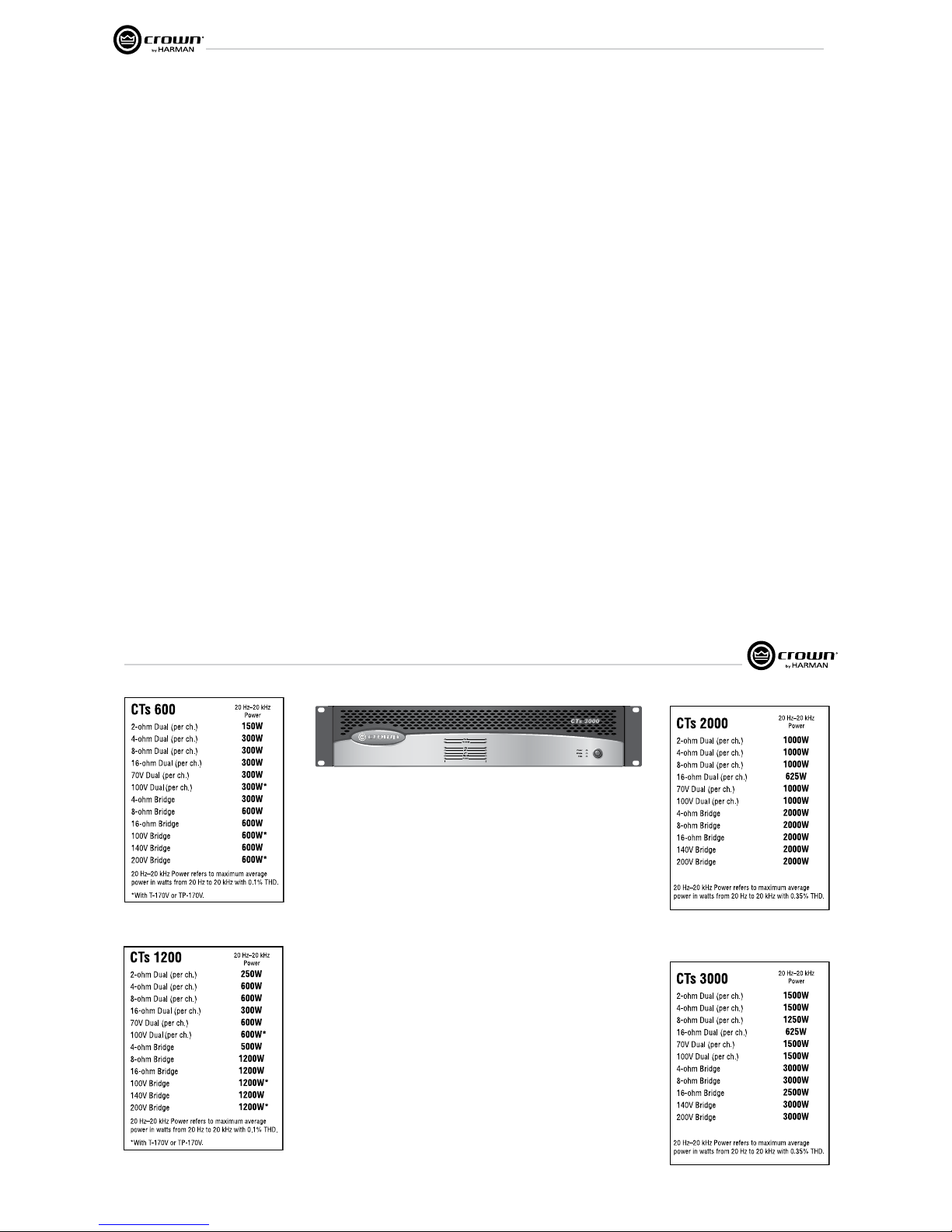
CTs 600
Obtaining Other Language Versions: To obtain information in another language about the use of this product, please contact your local
Crown Distributor. If you need assistance locating your local distributor, please contact Crown at 574-294-8000.
This manual does not include all of the details of design, production, or variations of the equipment. Nor does it cover every possible
situa tion which may arise during installation, operation or maintenance.
The information provided in this manual was deemed accurate as of the publication date. However, updates to this information may have
occurred. To obtain the latest version of this manual, please visit the Crown website at www.crownaudio.com.
Trademark Notice: Com-Tech, BCA, Crown, Crown Audio, Amcron and Multi-Mode are registered trademarks of Crown International.
IQwic, PIP and PIP2 are trademarks of Crown International. Other trademarks are the property of their respective owners.
© 2010 by Crown Audio®, Inc. 1718 W. Mishawaka Rd., Elkhart, Indiana 46517-9439 U.S.A. Telephone: 574-294-8000
141280-1
1/09
CTs 2-Channel Series Operation Manual
CTs 1200
CTs 2000
CTs 3000
Operation Manual
CTs Power Amplifiers
page 2 page 3
CTs Power Amplifiers
Operation Manual
1. Read these instructions.
2. Keep these instructions.
3. Heed all warnings.
4. Follow all instructions.
5. Do not use this apparatus near water.
6. Clean only with a dry cloth.
7. Do not block any ventilation openings. Install in accordance
with the manufacturer’s instructions.
8. Do not install near any heat sources such as radiators, heat
reg isters, stoves, or other apparatus (including amplifiers)
that produce heat.
9. Do not defeat the safety purpose of the polarized or
grounding-type plug. A polarized plug has two blades with
one wider than the other. A grounding-type plug has two
blades and a third grounding prong. The wide blade or
the third prong is provided for your safety. If the provided
plug does not fit into your outlet, consult an electrician for
replacement of the obsolete outlet.
10. Protect the power cord from being walked on or pinched,
par ticularly at plugs, convenience receptacles, and the
point where they exit from the apparatus.
11. Only use attachments/accessories specified by the manufac-
turer.
12. Use only with a cart, stand, tripod, bracket, or table
specified by the manufacturer, or sold with the apparatus.
When a cart is used, use caution when moving the cart/
apparatus combination to avoid injury from tip-over.
13. Unplug this apparatus during lightning storms or when
unused for long periods of time.
14. Refer all servicing to qualified service personnel. Servicing
is required when the apparatus has been damaged in any
way, such as power-supply cord or plug is damaged, liquid
has been spilled or objects have fallen into the apparatus,
the apparatus has been exposed to rain or moisture, does
not operate nor mally, or has been dropped.
15. Use the mains plug to disconnect the apparatus from the
mains.
16. WARNING: TO REDUCE THE RISK OF FIRE OR ELECTRIC
SHOCK, DO NOT EXPOSE THIS APPARATUS TO RAIN OR
MOISTURE.
17. DO NOT EXPOSE THIS EQUIPMENT TO DRIPPING OR
SPASHING AND ENSURE THAT NO OBJECTS FILLED
WITH LIQUIDS, SUCH AS VASES, ARE PLACED ON THE
EQUIPMENT.
18. THE MAINS PLUG OF THE POWER SUPPLY CORD SHALL
REMAIN READILY OPERABLE.
Important Safety Instructions
MAGNETIC FIELD
CAUTION! Do not locate sensitive high-gain equipment such as preamplifiers directly above or below the unit. Because this amplifier has a
high power density, it has a strong magnetic field which can induce hum
into unshielded devices that are located nearby. The field is strongest
just above and below the unit.
If an equipment rack is used, we recommend locating the amplifier(s)
in the bottom of the rack and the preamplifier or other sensitive equipment at the top.
The lightning bolt triangle is used to alert the user to the risk of
electric shock.
The exclamation point triangle is used to alert the user to
important operating or maintenance instructions.
REGARDEZ CES SYMBOLES:
La triangle avec le sigle ‘’foudre’’ est employée pour alerter
l’utilisateur au risque de décharge électrique. Le triangle avec
un point d’exclamation est employée pour alerter l’utilisateur
d’instruction importantes pour lors opérations de mainte nance.
ATENCION CON ESTOS SÍMBOLOS:
El triángulo con el símbolo de rayo eléctrico es usado para
alertar al usuario de el riesgo de un choque eléctrico.
El triángulo con el signo de admiración es usado para alertar
al usuario de instrucciones importantes de operación o mantenimiento.
WATCH FOR THESE SYMBOLS:
IMPORTANT
CTs Series amplifiers require Class 2 output wiring.
Les amplificateurs de série de CTs exigent des câbles de sortie de
classe 2.
CTs-Reihe-Verstärker verlangen Klasse die 2 Produktionsverdrah tung.
Los amplificadores de la Serie CTs requieren de un cableado de sal ida
Clase 2.
TO PREVENT ELECTRIC SHOCK DO NOT REMOVE TOP OR
BOTTOM COVERS. NO USER SERVICEABLE PARTS INSIDE.
REFER SERVICING TO QUALIFIED SERVICE PERSONNEL.
À PRÉVENIR LE CHOC ÉLECTRIQUE N’ENLEVEZ PAS LES
COUVERCLES. IL N’Y A PAS DES PARTIES SERVICEABLE
À L’INTÉRIEUR. TOUS REPARATIONS DOIT ETRE FAIRE PAR
PERSONNEL QUALIFIÉ SEULMENT.
PARA PREVENIR UN CHOQUE ELÉCTRICO, NO RETIRE LAS
CUBIERTAS SUPERIOR O INFERIOR. NO EXISTEN PARTES QUE
PUEDAN SER REPARADAS POR EL USUARIO AL INTE RIOR.
REMITA EL SERVICICO AL PERSONAL TÉCHNICAL CALIFICADO.
TO COMPLETELY DISCONNECT THIS EQUIPMENT FROM THE
AC MAINS, DISCONNECT THE POWER SUPPLY CORD PLUG
FROM THE AC RECEPTACLE. THE MAINS PLUG OF THE POWER
SUPPLY CORD SHALL REMAIN READILY OPERABLE.
POUR DÉMONTER COMPLÈTEMENT L’ÉQUIPEMENT DE
L’ALIMENTATION GÉNÉRALE, DÉMONTER LE CÂBLE D’ALIMENTATION DE SON RÉCEPTACLE. LA PRISE D’ALIMEN TATION
RESTERA AISÉMENT FONCTIONNELLE.
PARA DESCONECTAR COMPLETAMENTE EL EQUIPO DEL
SUMINSTRO ELECTRICO, DESCONECTE EL CABLE DE ALIMENTACION DE LA TOMA DE CA. LAS PATAS DEL CONEC TOR
DEL CABLE DE ALIMENTACIÓN DEBERAN MANTENERSE EN
BUEN ESTADO.
FCC COMPLIANCE NOTICE
This device complies with part 15 of the FCC rules. Operation is subject to the following
two conditions: (1) This device may not cause harmful interference, and (2) this device
must accept any interference received, including interference that may cause undesired
operation.
CAUTION: Changes or modifications not expressly approved by the party responsible for
compliance could void the user’s authority to operate the equipment.
NOTE: This equipment has been tested and found to comply with the limits for a Class B
digital device, pursuant to part 15 of the FCC Rules. These limits are designed to provide
reasonable protection against harmful interference in a residential installation. This equipment generates, uses, and can radiate radio frequency energy and, if not installed and used
in accordance with the instruction manual, may cause harmful interference to radio communications. However, there is no guarantee that interference will not occur in a particular
installation. If this equipment does cause harmful interference to radio or television reception, which can be determined by turning the equipment off and on, the user is encouraged
to try to correct the interference by one or more of the following measures:
• Reorient or relocate the receiving antenna.
• Increase the separation between the equipment and receiver.
• Connect the equipment into an outlet on a circuit different from that to which the
receiver is connected.
• Consult the dealer or an experienced radio/TV technician for help.
Importantes Instructions de Sécurité
Wichtige Sicherheitsinstruktionen
Instrucciones de Seguridad Importantes
Crown Audio, Inc.
European Representative’s Name and Address:
David Budge
10 Harvest Close
Yateley GU46 6YS
United Kingdom
Equipment Type: Commercial Audio Power Amplifiers
Family Name: CTs
Model Names: CTs 3000, CTs 2000, CTs 1200, CTs 600
EMC Standards:
EN 55103-1:1997 Electromagnetic Compatibility - Product Family Standard for Audio, Video, Audio-Visual and Entertainment Lighting Control Apparatus for Professional Use, Part 1: Emissions
EN 55103-1:1997 Magnetic Field Emissions-Annex A @ 10 cm and 1 M
EN 61000-3-2:1995+A14:2000 Limits for Harmonic Current Emissions (equipment input current £16A per phase)
EN 61000-3-3:1995 Limitation of Voltage Fluctuations and Flicker in Low-Voltage Supply Systems Rated Current £16A
EN 55022:2003 Limits and Methods of Measurement of Radio Disturbance Characteristics of ITE: Radiated, Class B Limits; Conducted, Class B
EN 55103-2:1997 Electromagnetic Compatibility - Product Family Standard for Audio, Video, Audio-Visual and Entertainment Lighting Control Apparatus for Professional Use, Part 2: Immunity
EN 61000-4-2:2003 Electrostatic Discharge Immunity (Environment E2-Criteria B, 4k V Contact, 8k V Air Discharge)
EN 61000-4-3:2003 Radiated, Radio-Frequency, Electromagnetic Immunity (Environment E2, criteria A)
EN 61000-4-4:2005 Electrical Fast Transient/Burst Immunity (Criteria B)
EN 61000-4-5:2001 Surge Immunity (Criteria B)
EN 61000-4-6:1996 Immunity to Conducted Disturbances Induced by Radio-Frequency Fields (Criteria A)
EN 61000-4-11:2004 Voltage Dips, Short Interruptions and Voltage Variation
Safety Standard:
EN 60065: 1998 Safety Requirements - Audio Video and Similar Electronic Apparatus
I certify that the product identified above conforms to the requirements of the EMC Council Directive 89/336/EEC as amended by 92/31/EEC, and the Low Voltage Directive 73/23/EES as amended by 93/68/EEC.
Signed
ISSUED BY: Crown Audio, Inc.
1718 W. Mishawaka Road
Elkhart, Indiana 46517 U.S.A.
Andrew Stump
Title: Director of Manufacturing
CTs Power Amplifiers
Operation Manual
DECLARATION of CONFORMITY
Crown Audio, Inc.
Sue Whitfield
574-294-8289
swhitfield@crownintl.com
European Representative’s Name and Address:
David Budge
10 Harvest Close
Yateley GU46 6YS
United Kingdom
Equipment Type: Commercial Audio Power Amplifiers
Family Name: CTs
Model Names: CTs 3000, CTs 2000, CTs 1200, CTs 600
EMC Standards:
EN 55103-1:1997 Electromagnetic Compatibility - Product Family Standard for Audio, Video, Audio-Visual and Entertainment Lighting Control Apparatus for Professional Use, Part 1: Emissions
EN 55103-1:1997 Magnetic Field Emissions-Annex A @ 10 cm and 1 M
EN 61000-3-2:1995+A14:2000 Limits for Harmonic Current Emissions (equipment input current £16A per phase)
EN 61000-3-3:1995 Limitation of Voltage Fluctuations and Flicker in Low-Voltage Supply Systems Rated Current £16A
EN 55022:2003 Limits and Methods of Measurement of Radio Disturbance Characteristics of ITE: Radiated, Class B Limits; Conducted, Class B
EN 55103-2:1997 Electromagnetic Compatibility - Product Family Standard for Audio, Video, Audio-Visual and Entertainment Lighting Control Apparatus for Professional Use, Part 2: Immunity
EN 61000-4-2:2003 Electrostatic Discharge Immunity (Environment E2-Criteria B, 4k V Contact, 8k V Air Discharge)
EN 61000-4-3:2003 Radiated, Radio-Frequency, Electromagnetic Immunity (Environment E2, criteria A)
EN 61000-4-4:2005 Electrical Fast Transient/Burst Immunity (Criteria B)
EN 61000-4-5:2001 Surge Immunity (Criteria B)
EN 61000-4-6:1996 Immunity to Conducted Disturbances Induced by Radio-Frequency Fields (Criteria A)
EN 61000-4-11:2004 Voltage Dips, Short Interruptions and Voltage Variation
Safety Standard:
EN 60065: 1998 Safety Requirements - Audio Video and Similar Electronic Apparatus
I certify that the product identified above conforms to the requirements of the EMC Council Directive 89/336/EEC as amended by 92/31/EEC, and the Low Voltage Directive 73/23/EES as amended by 93/68/EEC.
Signed
Date of Issue: March 1, 2002
ISSUED BY: Crown Audio, Inc.
1718 W. Mishawaka Road
Elkhart, Indiana 46517 U.S.A.
Due to line current harmonics, we recommend that you contact your supply authority before connection.
FOR COMPLIANCE QUESTIONS ONLY:
Andrew Stump
Title: Director of Manufacturing
Operation Manual
CTs Power Amplifiers
page 4 page 5
CTs Power Amplifiers
Operation Manual
Important Safety Instructions ......................................2
Declaration of Conformity ...........................................3
1 Welcome .........................................5
1.1 Features ...........................................................5
2 How to Use This Manual ........................6
3 Setup ..............................................7
3.1 Unpack Your Amplifier .....................................7
3.2 Install Your Amplifier ........................................7
3.3 Ensure Proper Cooling .....................................7
3.4 Choose Input Wire and Connectors ..................8
3.5 Choose Output Wire and Connectors ...............8
3.6 Wire Your System .............................................9
3.6.1 Dual 8/4/2 Mode ......................................9
3.6.2 Bridge-Mono 16/8/4 Mode .......................9
3.6.3 Dual 70V/100V Mode ...............................10
3.6.4 Bridge-Mono 140V/200V Mode ...............10
3.6.5 Dual Mode with “Y” Input .........................11
3.7 Connect to AC Mains .......................................12
3.8 Startup Procedure ............................................12
4 Operation .........................................12
4.1 Precautions ......................................................12
4.2 Front Panel Controls and Indicators .................13
4.3 Back Panel Controls and Connectors ...............14
5 Advanced Features and Options ...............15
5.1 Protection Systems ..........................................15
5.1.1 Thermal Level Control (TLC) ....................15
5.1.2 Junction Temperature Simulation (JTS).....15
5.1.3 Fault .........................................................15
5.1.4 High-Pass Filters .....................................15
5.1.5 Low-Pass Filters ......................................15
5.1.6 AC Under/Over Voltage Protection ...........15
5.1.7 Circuit Breaker .........................................15
5.1.8 DC Output Servo ......................................15
5.1.9 Inrush Limiting .........................................15
5.1.10 Variable-speed Fans ...............................15
5.2 Advanced Features ...........................................15
5.2.1 Switching Power Supply ..........................15
5.2.2 Input Compressor ....................................15
5.2.3 Sleep Circuit .............................................15
5.2.4 Input Sensitivity Switches ........................16
5.3 Options ............................................................16
5.3.1 Nominal Attenuation Settings ...................17
6 Troubleshooting ..................................18
7 Specifications ....................................20
8 AC Power Draw and Thermal Dissipation .....24
9 Service ............................................28
9.1. International and Canada Service ....................28
9.2 US Service .......................................................28
9.2.1 Service at a US Service Center .................. 28
9.2.2 Factory Service ........................................ 28
9.2.3 Factory Service Shipping Instructions ....... 28
9.2.4 Packing Instructions .................................28
9.2.5 Estimate Approval .....................................28
9.2.6 Payment of Non-Warranty Repairs.............28
10 Warranty ........................................29
Factory Service Information Form ............................... 31
Product Registration Form ...........................................33
Table of Contents
CTs Power Amplifiers
Operation Manual
1 Welcome
Building on the foundation of the Com-Tech®
Series, the Crown®CTs Series offers new
flexi bility and value for installed sound. The
Com-Tech Series was the first to offer
independent selection of high- and lowimpedance opera tion for a specific channel, and
CTs Series amplifiers continue that tradition,
with power levels and features carefully chosen
to perfectly integrate into fixed install design
requirements.
Modern power amplifiers are sophisticated
pieces of engineering capable of producing
extremely high power levels. They must be
treated with respect and correctly installed if
they are to provide the many years of reliable
service for which they were designed.
In addition, CTs Series amplifiers include a
number of features which require some
expla nation before they can be used to their
maxi mum advantage.
Please take the time to study this manual so that
you can obtain the best possible service from
your amplifier.
1.1 Features
• Switching Power Supply for reduced
weight.
• High power-density, with all two-channel
models in a 2U chassis.
• Direct constant-voltage
(70V/140V) or low-impedance (2/4/8 ohm)
operation. No switch required.
• Input sensitivity is independently
select able for each channel. Choose lowimped ance (4/8 ohm), constant-voltage
(70V/100V/140V/200V), or 26 dB.
• TLC protection circuitry protects the
amplifier from long-term excessive heat by
subtly and dynamically reducing the gain
only when necessary.
• JTS circuitry (CTs 600/1200 only) quickly
protects BJT output transistors from unsafe
operating conditions without shut ting the
channel down. (Not applicable to BCA
amplifiers as they are inherently pro tected.)
• PIP2™ (Programmable Input Processor)
connector accepts accessory modules that
tailor the amplifier to suit specific
applica tions.
• Removable terminal block input
connec tors, with “Y” Input Switch in the
standard PIP2-BBY module.
(Continued on next page)
Operation Manual
CTs Power Amplifiers
page 6 page 7
CTs Power Amplifiers
Operation Manual
• Legendary Crown class I (BCA®) and class
AB+B (Multi-Mode ®) output topol ogies
offer the best in amplifier reliability. CTs
600/1200 use Class AB+B; CTs 2000/3000
use Class I.
• Class I is the lowest distortion, lowest
noise, and highest performing topology
available among switch-mode amplifiers.
• Continuously-variable fans optimize
cool ing efficiency.
• Three Year, No-Fault, Fully-Transferable
Warranty completely protects your
invest ment and guarantees its specifications.
2 How to Use This
Manual
This manual provides you with the necessary
information to safely and correctly setup and
operate your amplifier. It does not cover every
aspect of installation, setup or operation that
might occur under every condition. For
addi tional information, please consult Crown’s
Amplifier Application Guide (available online at
www.crownaudio.com), Crown Tech Support,
your system installer or retailer.
We strongly recommend you read all
instruc tions, warnings and cautions contained
in this manual. Also, for your protection, please
send in your warranty registration card today.
And save your bill of sale—it’s your official
proof of purchase.
Features (continued from page 5)
• Switchable high-pass filter for each chan nel
provides low-frequency roll off to elim inate
step down transformer saturation when used
in distributed systems.
• Comprehensive array of indicators includ ing
Power, Data, and Bridge; along with Ready,
Signal, Clip, Thermal and Fault for each
channel, provide accurate diagnos tics.
• Blue Power Indicator flashes if the ampli fier
shuts off due to an under/over-voltage
condition on the AC mains.
• Advanced protection circuitry guards against:
shorted outputs, DC, mismatched loads,
general overheating, under-/over-voltage,
high-frequency overloads and internal faults.
1 Welcome
3 Setup
CTs Power Amplifiers
Operation Manual
3.1 Unpack Your Amplifier
Please unpack and inspect your amplifier for
any damage that may have occurred during
transit. If damage is found, notify the
transpor tation company immediately. Only you
can ini tiate a claim for shipping damage. Crown
will be happy to help as needed. Save the
shipping carton as evidence of damage for the
shipper’s inspection.
We also recommend that you save all packing
materials so you will have them if you ever need
to transport the unit. Never ship the unit
without the factory pack.
YOU WILL NEED (not supplied):
• Input wiring cables
• Output wiring cables
• Phillips screwdriver
Rack for mounting amplifier (or a stable surface
for stacking)
WARNING: Before you start to set up
your amplifier, make sure you read and
observe the Important Safety Instructions found at the beginning of this
manual.
3.2 Install Your Amplifier
CAUTION: Before you begin, make sure
your amplifier is disconnected from the
power source, with power switch in the
“off” position and all level controls
turned completely down (counterclockwise).
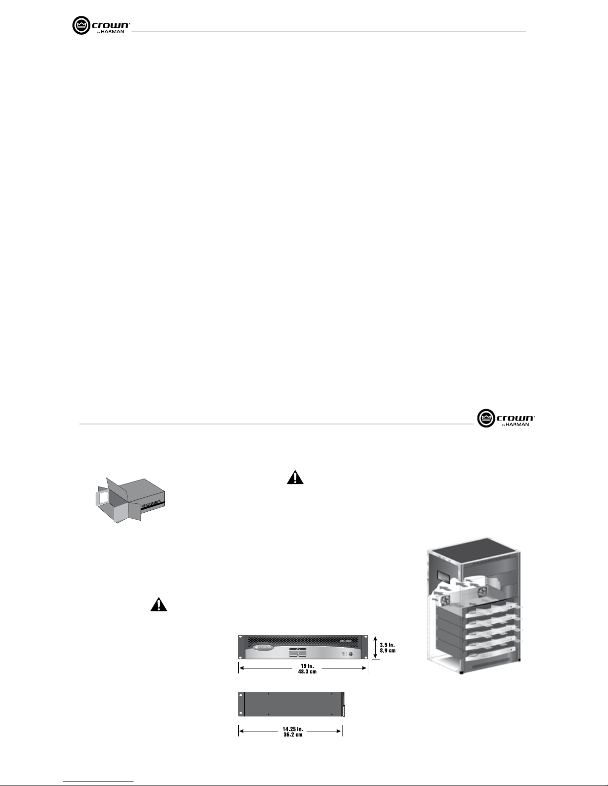
Use a standard 19-inch (48.3 cm) equipment
rack. See Figure 3.1 for amplifier dimensions.
You may also stack amps without using a
cabi net.
NOTE: When transporting, amplifiers should be
supported at both front and back.
3.3 Ensure Proper Cooling
When using an equipment rack, mount units
directly on top of each other. Close any open
spaces in rack with blank panels. DO NOT block
front or rear air vents. The side walls of the rack
should be a minimum of two inches (5.1 cm)
away from the amplifier sides, and the back of
the rack should be a minimum of four inches
(10.2 cm) from the amplifier back panel.
Figure 3.2 illustrates standard amplifier airflow.
Figure 3.1 CTs 2-Channel Series Dimensions
Figure 3.2 Airflow
3 Setup
Operation Manual
CTs Power Amplifiers
page 8 page 9
CTs Power Amplifiers
Operation Manual
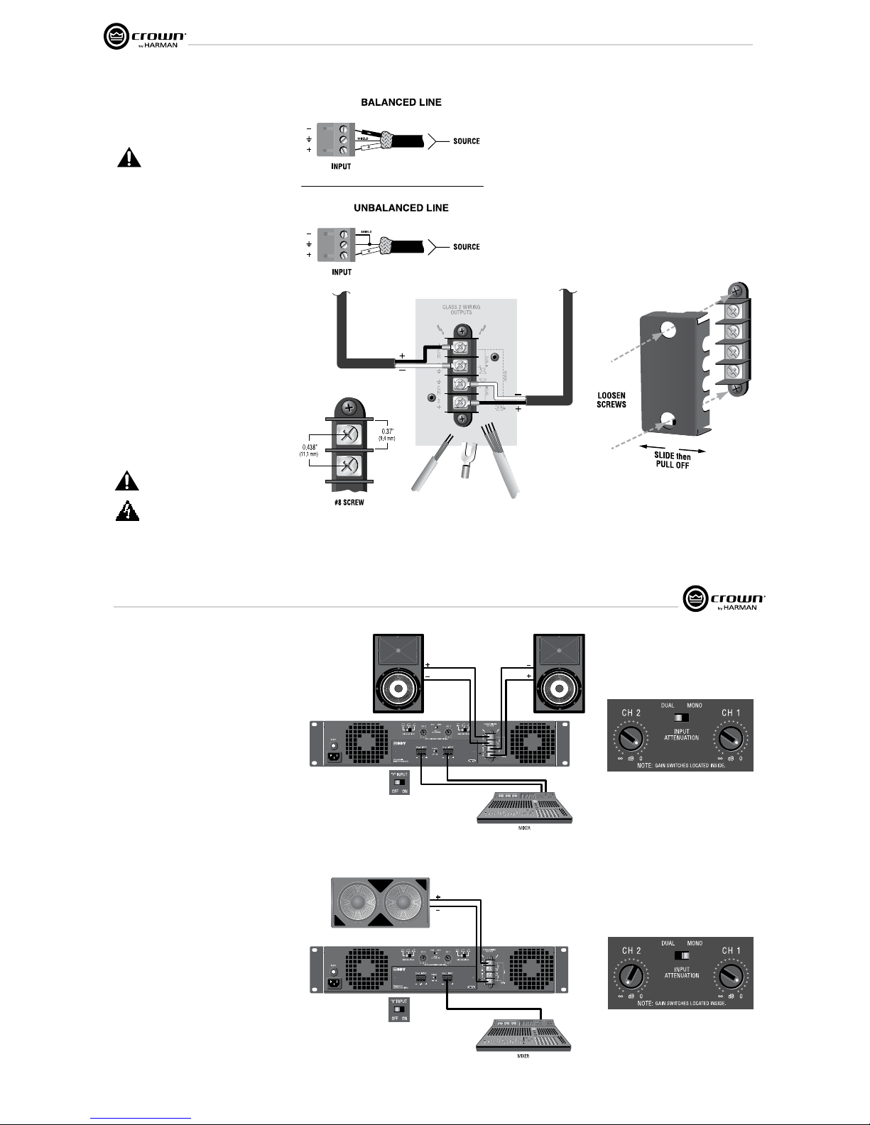
3.4 Choose Input Wire
and Connectors
Figure 3.3 shows connector pin assignments for
balanced wiring, and Figure 3.4 shows connec tor
pin assignments for unbalanced wiring.
NOTE: Custom wiring should only be
per formed by qualified personnel.
3.5 Choose Output Wire and
Con nectors
A protective cover is installed over the barrierstrip output. Some models have a cover with two
holes. To remove this type of cover:
1. Loosen screws inside top and bottom holes of
cover (see Figure 3.6).
2. Slide cover to left or right, then pull it off away
from the amplifier.
3. Tighten screws.
Crown recommends using professionally
con structed, high-quality, two- or four-conductor,
heavy gauge speaker wire and connectors. You
may use terminal forks up to 10 AWG or bare wire
for your output connectors (see Figure 3.5). To
prevent the possibility of short-circuits, wrap or
otherwise insulate exposed loudspeaker cable
connectors. For best results, Crown recom mends
Panduit part #PV10-10LF-L or equivalent
terminal fork. Screw spacing is shown in Figure
3.5.
Using the guidelines below, select the appropri ate
size of wire based on the distance from amplifier
to speaker (low-impedance loads only).
Distance Wire Size
up to 25 ft. (7.6m) 16 AWG
26-40 ft. (7.9-12.2m) 14 AWG
41-60 ft. (12.5-18.3m) 12 AWG
> 60 ft (18.3m) 10 AWG
CAUTION: Never use shielded cable for
output wiring.
Replace output cover after output wiring is
complete.
Figure 3.5 Typical Output Connector Wiring
3 Setup
Figure 3.3
Balanced Input
Connector Wiring
Figure 3.4
Unbalanced Input
Connector Wiring
Figure 3.6 How to Remove the Two-Holed
Barrier-Block Cover
3.6 Wire Your System
3.6.1 Dual 8/4/2 Mode
Typical input and output wiring, along with Attenuator
and Mode Switch settings are shown in Figures 3.6 and
3.7. Make sure the Mode switch is set to the “Dual”
posi tion when operating in Dual mode.
INPUTS: Connect input wiring for each channel. The Y
switch on the rear PIP panel can be used to parallel the
channel inputs when only mono input signals are
neces sary. The amplifier’s channel outputs are still
indepen dent.
OUTPUTS: Maintain proper polarity (+/–) on
output connectors.
Connect the Channel 1 speaker’s positive (+) lead to
amplifier Channel 1 positive terminal; repeat for negative
(–). Repeat Channel-2 wiring as for Channel 1. Refer to
Section 3.5 for output connector pin assignments.
3.6.2 Bridge-Mono 16/8/4 Mode
Typical input and output wiring, along with Attenuator
and Mode Switch settings, are shown in Figures 3.8 and
3.9. Make sure the Mode switch is set to the “Mono”
position when operating in Bridge-Mono mode.
INPUTS: Connect input wiring to Channel 1 only.
OUTPUTS: Connect the speaker across the positive
ter minals of each channel pair. Do not use the negative
ter minals of the channel pair when the pair is being
operated in Bridge-Mono mode. Refer to Section 3.5 for
output connector pin assignments.
NOTE: Crown provides a reference of wiring pin
assign ments for commonly used connector types in the
Crown Amplifier Application Guide available at
www.crownaudio.com.
NOTE: When operating in Bridge-Mono mode,
turn down (full CCW) the Input Attenuator for
Channel 2. The Channel-1 Input Atttenuator
works both channels.
See the next page for constant-voltage operation.
3 Setup
CTs Power Amplifiers
Operation Manual
3.6 Wire Your System
3.6.1 Dual 8/4/2 Mode
Typical input and output wiring, along with Attenuator
and Mode Switch settings are shown in Figures 3.6 and
3.7. Make sure the Mode switch is set to the “Dual”
posi tion when operating in Dual mode.
INPUTS: Connect input wiring for each channel. The Y
switch on the rear PIP panel can be used to parallel the
channel inputs when only mono input signals are
neces sary. The amplifier’s channel outputs are still
indepen dent.
OUTPUTS: Maintain proper polarity (+/–) on
output connectors.
Connect the Channel 1 speaker’s positive (+) lead to
amplifier Channel 1 positive terminal; repeat for negative
(–). Repeat Channel-2 wiring as for Channel 1. Refer to
Section 3.5 for output connector pin assignments.
3.6.2 Bridge-Mono 16/8/4 Mode
Typical input and output wiring, along with Attenuator
and Mode Switch settings, are shown in Figures 3.8 and
3.9. Make sure the Mode switch is set to the “Mono”
position when operating in Bridge-Mono mode.
INPUTS: Connect input wiring to Channel 1 only.
OUTPUTS: Connect the speaker across the positive
ter minals of each channel pair. Do not use the negative
ter minals of the channel pair when the pair is being
operated in Bridge-Mono mode. Refer to Section 3.5 for
output connector pin assignments.
NOTE: Crown provides a reference of wiring pin
assign ments for commonly used connector types in the
Crown Amplifier Application Guide available at
www.crownaudio.com.
NOTE: When operating in Bridge-Mono mode,
turn down (full CCW) the Input Attenuator for
Channel 2. The Channel-1 Input Atttenuator
works both channels.
See the next page for constant-voltage operation.
Figure 3.7 System Wiring, Dual Mode.
Figure 3.8 Attenuator and Mode-
Switch Settings for Dual Mode
Figure 3.9 System Wiring, Bridge-Mono Mode
Figure 3.10 Attenuator and Mode-
Switch Settings for Bridge-Mono Mode
3 Setup
Always route the input and output
wires in separate bundles.
Operation Manual
CTs Power Amplifiers
page 10 page 11
CTs Power Amplifiers
Operation Manual
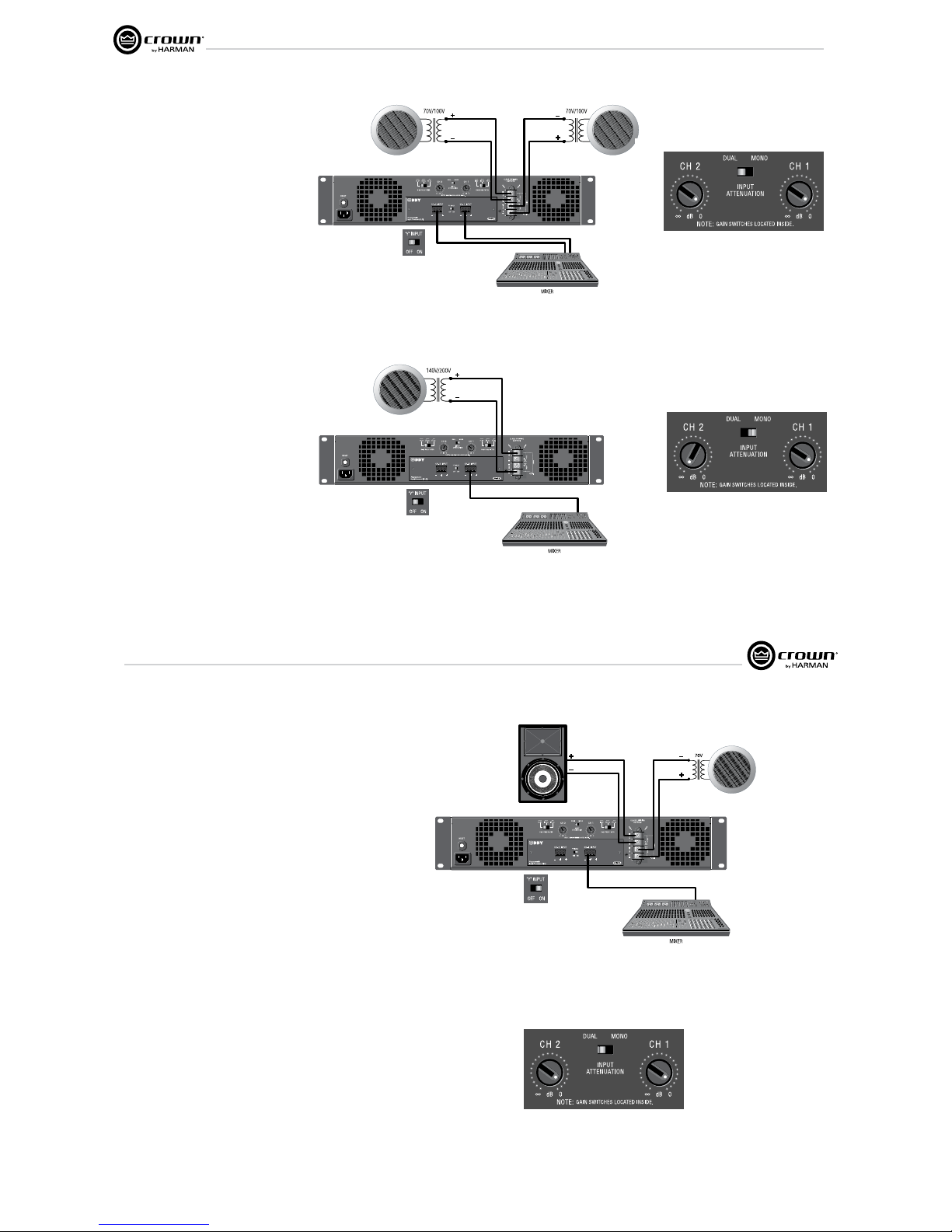
3.6.3 Dual 70V/100V Mode
Typical input and output wiring, along with
Atten uator and Mode Switch settings are shown in
Fig ures 3.10 and 3.11. Make sure the Mode
switch is set to the “Dual” position when operating
in Dual mode.
INPUTS: Connect input wiring to both channels.
OUTPUTS: In Dual Mode, the CTs 600/1200 can
power 25/50/70V lines; the CTs 2000/3000 can
power 25/50/70/100V lines. Connect each
chan nel of output connectors to speakers that
have the appropriate transformers.
.
3.6.4 Bridge-Mono 140V/200V Mode
Typical input and output wiring, along with
Atten uator and Mode Switch settings are shown in
Fig ures 3.12 and 3.13. Make sure the Mode
switch is set to the “Mono” position when
operating in Bridge-Mono mode.
INPUTS: Connect input wiring to Channel 1 only.
OUTPUTS: In Bridge-Mono mode, the CTs
600/1200 can power 140V lines; the CTs
2000/3000 can power 140V and 200V lines.
Connect speak ers with 140V or 200V
transformers across the positive terminals of the
channel pair. Do not use the negative terminals of
the channel pair when the pair is being operated in
Bridge-Mono mode. Refer to Section 3.5 for
output connector pin assignments.
NOTE: When operating in Bridge-Mono
mode, turn down (full CCW) the Input
Attenuator for Channel 2. The Channel-1
Input Attenuator works both channels.
Figure 3.11 System Wiring and Y-Switch Setting for 70V/100V Operation
Figure 3.12 Attenuator and Mode-Switch
Settings for 70V/100V Operation
Figure 3.13 System Wiring and Y-Switch Setting for 140V/200V Operation
Figure 3.14 Attenuator and Mode-Switch
Settings for 140V/200V Operation
3 Setup
Always route the input and output wires in
separate bundles.
3.6.5 Dual Mode with “Y” Input
See Figure 3.14. This configuration feeds a mono
signal to both Channel 1 and Channel 2. In the
example in Figure 3.14, Channel 1 is driving a low-
impedance loudspeaker and Channel 2 is driving a
loudspeaker with a 70V transformer.
INPUTS:
Connect the signal to the Channel 1 input. On the
back panel, set the “Y” Input Switch to ON.
OUTPUTS:
Connect the Channel 1 speaker’s positive (+) lead to
Channel 1 positive terminal of amp; repeat for
negative (–).
Connect the Channel 2 speaker’s positive (+) lead to
Channel 2 positive terminal of amp; repeat for
negative (–).
See Figure 3.15. Turn up both Input Attenuators and
set the Mode Switch to Dual.
NOTE: When the “Y” Input Switch is on, the Chan nel
2 input can be used to daisy-chain to another
amplifier.
3 Setup
CTs Power Amplifiers
Operation Manual
3.6.5 Dual Mode with “Y” Input
See Figure 3.14. This configuration feeds a mono
signal to both Channel 1 and Channel 2. In the
example in Figure 3.14, Channel 1 is driving a lowimpedance loudspeaker and Channel 2 is driving a
loudspeaker with a 70V transformer.
INPUTS:
Connect the signal to the Channel 1 input. On the
back panel, set the “Y” Input Switch to ON.
OUTPUTS:
Connect the Channel 1 speaker’s positive (+) lead to
Channel 1 positive terminal of amp; repeat for
negative (–).
Connect the Channel 2 speaker’s positive (+) lead to
Channel 2 positive terminal of amp; repeat for
negative (–).
See Figure 3.15. Turn up both Input Attenuators and
set the Mode Switch to Dual.
NOTE: When the “Y” Input Switch is on, the Chan nel
2 input can be used to daisy-chain to another
amplifier.
Figure 3.15 System Wiring for “Y” Input Mode
Figure 3.16
Attenuator and Mode-Switch
Settings for “Y” Input Mode
3 Setup
Always route the input and output wires in
separate bundles.
 Loading...