

Page 1

Crestron MM-DS-12
MediaManifold® High-Definition CATV
Distribution System
Operations & Installation Guide
Page 2

Regulatory Compliance
CAN ICES-3(B)/NMB-3(B)
As of the date of manufacture, the MM-DS-12 has been tested and found to comply with specifications for
CE marking.
Federal Communications Commission (FCC) Compliance Statement
This device complies with part 15 of the FCC Rules. Operation is subject to the following conditions:
(1) This device may not cause harmful interference and (2) this device must accept any interference received,
including interference that may cause undesired operation.
CAUTION: Changes or modifications not expressly approved by the manufacturer responsible for
compliance could void the user’s authority to operate the equipment.
NOTE: This equipment has been tested and found to comply with the li mits for a Class B digital device,
pursuant to part 15 of the FCC Rules. These limits are designed to provide reasonable protection against
harmful interference in a residential installation. This equipment generates, uses and can radiate radio
frequency energy and, i f not instal led and used in accordance with the instructions, may cause harmful
interference to radio communications. However, there is no guarantee that interference will not occur in a
particular installation. If this e quipment does cause harmful interference to radio or television reception,
which can be determined by turning the equipment off and on, the user is encouraged to try to correct the
interference by one or more of the following measures:
• Reorient or relocate the receiving antenna
• Increase the separation between the equipment and receiver
• Connect the equipment into an outlet on a circuit different from that to which the receiver is connected
• Consult the dealer or an experienced radio/TV technician for help
Industry Canada (IC) C ompliance Statement
The specific patents that cover Crestron products are list ed at patents.crestron.com.
Crestron, the Crestron logo, and MediaManifold are either trademarks or registered trademarks of Crestron Electronics, Inc. in the Un ited States and/or
other countries. FiOS is either a trademark or a registered trademark of Verizon in the United States and/or other countries. Other trademark s,
registered trademarks, and trade names may be used in this document to refer to either the entities claim ing the marks and names or their produc ts .
Crestron disclaims any proprietary interest in the marks and names of others. Crestron is not r esponsible for errors in typography or photography.
This document was written by the Technical Publications department at Crestron.
©2014 Crestron Electronics, Inc.
Page 3

Crestron MM-DS-12 MediaManifold CATV Distribution System
Contents
MediaManifold CATV Distribution System: MM-DS-12 1
Introduction ............................................................................................................................... 1
Features and Functions ................................................................................................ 1
Theory ......................................................................................................................... 2
Applications................................................................................................................. 5
Specifications .............................................................................................................. 6
Physical Description .................................................................................................... 7
Setup ........................................................................................................................................ 11
Supplied Hardware .................................................................................................... 11
Installation ................................................................................................................. 11
Hardware Hookup ..................................................................................................... 12
Operation ................................................................................................................................. 15
Operating Modes ....................................................................................................... 15
Configure a Zone ....................................................................................................... 15
Restore Factory Settings ............................................................................................ 16
Problem Solving ...................................................................................................................... 17
Troubleshooting ......................................................................................................... 17
Reference Documents ................................................................................................ 17
Further Inquiries ........................................................................................................ 17
Future Updates .......................................................................................................... 18
Return and Warranty Policies .................................................................................................. 19
Merchandise Returns / Repair Service ...................................................................... 19
CRESTRON Limited Warranty................................................................................. 19
Operations & Installation Guide – DOC. 6600C Contents • i
Page 4

Page 5

Crestron MM-DS-12 MediaManifold CATV Distribution System
• 12-zone CATV distribution system
MediaManifold CATV Distribution
System: MM-DS-12
Introduction
The Crestron® MediaManifold® MM-DS-12 is a 12-zone bidirectional CATV
distribution amplifier featuri ng individual gain and tilt adjust ment on every o utput.
The MM-DS-12 integrates all of the elements of a complete professiona l he adend
into a single compact module. High power and headroom combine with low noise
and distortion to deliver exceptional performance for distributing both analog and
digital cable TV signals.*
Features and Functions
• Expandable from 24 to 576 zones
• High-power, high-headroom, low-noise, and low-distortion
• Supports bidirectional cable runs up to 300 feet (91 meters) each
• Individual gain and tilt a djustments per zone
• Automatic setup using M M-HTDR Cable Analyzer
• Built-in cable modem output and modulator input
• Compact surface wall-mount design
Simplicity without Compromise
Designing and installing a high-perfor mance residential or small commercial cable
TV system is easy with the MM-DS-12. The MM-DS-12 eliminates the numerous
splitters, combiners, amplifiers, and cables that make up an ordinary distrib ution
system, rep lacing the m all with a single, compact surface-mount module. Each of its
12 zone outputs supports up to 300 feet (91 meters) of homerun RG6 coaxial cable
feeding a single television or set-top box. An additional output is provided for cable
modem and digital phone, and an external modulator can also be connected to enable
signals from security cameras and other video sources to be combined and
distributed along with the main cable TV channels.
* Not compatible with systems utilizing a MoCA (Multimedia over Coax Alliance) based media service
such as Veri zo n FiOS
®
.
Operations & Installation Guide – DOC. 6600C MediaManifold CATV Distribution System: MM-DS-12 • 1
Page 6

MediaManifold CATV Distribution System Crestron MM-DS-12
Frequency (MHz)
Fr eq. Response Af ter 5 f t (1.5 m) of Cable
Gain ( dB )
Automatic Adjustment
Compared to conventional CATV distribution amps, MediaManifold offers much
greater capability for proper adjustment, providing independent gain and tilt settings
for every zone. Adjusting these settings is extremely easy with MediaManifold.
Simply by entering the cable length for each zone, the MM-DS-12 sets the optimum
gain and tilt settings automatically.
Determining the cable lengths is also very simple using the optional MM-HTDR
Cable Analyzer.* The MM-HTDR employs st a t e-of-the-art "time domain
reflectometry" to determine the length and integrity of each RG6 cable run. At the
press of a button, the MM-HTDR analyzes the cable and transfers the length
measurement to the MM-DS-12, setting the appropriate gain and tilt values
automatically.
Easy Expansion
Adding the MM-DE-12 MediaManifold Expander* provides 12 additional output
zones. Housed in an identical compact module, the MM-DE-12 connects to the
MM-DS-12 using three “F” cables, supporting 24 zones total with automatic gain
and tilt adjustment for every zone output. Additional zones can be achieved by
cascading any zone connection to a second MediaManifold system, enabling
complete systems of over 500 zones.
Theory
Original Signal
The originating signal from the local cable o perator is a mostly flat signal at
approximately 0 dBmV as shown in the following diagram.
Originating Cable Signal
* Sold separately.
2 • MediaManifold CATV Distribution System: MM-DS-12 Operations & Installation Guide – DOC. 6600C
Page 7

Crestron MM-DS-12 MediaManifold CATV Distribution System
Frequency (MHz)
Cable Drop at 300 ft ( 91 m )
Gain ( dB )
Frequency (MHz)
Fr eq. ResponseAfter Tilt Corr ec tion - 13 dB
Gain ( dB )
Cable Drop
When using longer length cable runs, the overal l signal strength drops while the
signal strength at the higher frequencies has a greater decrease as shown in the
following diagram.
Frequency Response on 300 Feet of Cable without Gain or Tilt Compensation
Setting the Cable Length
Setting the cable length on the MM-DS-12 lowers the signal strength of the low-end
frequencie s to the level of the high-end frequencies (tilt) and raises the signal
strength (gain) to match the original input signal. Refer to the following diagrams.
Frequency Response on 300 Feet of Cable with Tilt Compensation (No Gain Adjustment)
Operations & Installation Guide – DOC. 6600C MediaManifold CATV Distribution System: MM-DS-12 • 3
Page 8

MediaManifold CATV Distribution System Crestron MM-DS-12
Gain ( dB )
Frequency (MHZ)
Fr eq. ResponseAfter 300 f t (91 m) Cable
and 23 dB G ain Com pens ation
Frequency Response on 300 Feet of Cable with Tilt and Gain Compensation
4 • MediaManifold CATV Distribution System: MM-DS-12 Operations & Installation Guide – DOC. 6600C
Page 9

Crestron MM-DS-12 MediaManifold CATV Distribution System
Applications
The following diagra m s hows an MM-DS-12 in a r e sidential application.
MM-DS-12 in a Residential Application
Operations & Installation Guide – DOC. 6600C MediaManifold CATV Distribution System: MM-DS-12 • 5
Page 10

MediaManifold CATV Distribution System Crestron MM-DS-12
Specifications
Specifications for the MM-DS-12 are listed in the following table.
MM-DS-12 Specifications
SPECIFICATION DETAILS
RF
Forward Bandwidth 54 MHz to 1 GHz
Reverse Bandwidth 5 MHz to 42 MHz
Minimum Output Cable
Length
Maximum Output Cable
Length
Gain 23 dB
Gain Adjust -6 dB to 25 dB
Tilt Adjust 0 dB to 31 dB
Isolation > 45 dB
Power Requirements 5 A @ 5 Vdc regulated
Power Supply (included) 120 Vac, 60 Hz
Enclosure Chromium-plated aluminum with black
Environmental
Temperature 41º to 104º F (5º to 40º C)
Humidity 10% to 90% RH (non-condensing)
Heat Dissipation 68 Btu/h
Dimensions
Height 11.05 in (281 mm)
Width 10.42 in (265 mm)
Depth 2.54 in (65 mm)
Weight 5.9 lbs (2.7 kg)
Available Accessories
CAEN Automation Enclosure
CAEN-UMP Universal Mounting Plates
MM-DE-12 MediaManifold Expander
MM-HTDR MediaManifold Cable Analyzer
5 feet (1.5 meters)
300 feet (91 meters)
powder-coated steel end panels and
polycarbonate label overlay, surface-mount
with integral heat-sinks and (2) mounting
flanges
6 • MediaManifold CATV Distribution System: MM-DS-12 Operations & Installation Guide – DOC. 6600C
Page 11

Crestron MM-DS-12 MediaManifold CATV Distribution System
Physical Description
This sectio n provides information on the connections, co ntrols, and indicators
available on the MM-DS-12.
MM-DS-12 Physical View
Operations & Installation Guide – DOC. 6600C MediaManifold CATV Distribution System: MM-DS-12 • 7
Page 12

MediaManifold CATV Distribution System Crestron MM-DS-12
7.96 in
(202 mm)
1.54 in
10.70 in
9
.87 i
n
1
0.42 i
n
2
.54 in
(65 mm)
Ø
4
P
laces
11.05
in
(281 mm)
1
2
3
4
5
6
1
4
9
1
1
12
7
8
1
0
13
0.19 in (5 mm),
(272 mm)
(39 mm)
4
(265 mm)
(251 mm)
MM-DS-12 Overall Dimensions
8 • MediaManifold CATV Distribution System: MM-DS-12 Operations & Installation Guide – DOC. 6600C
Page 13
Crestron MM-DS-12 MediaManifold CATV Distribution System
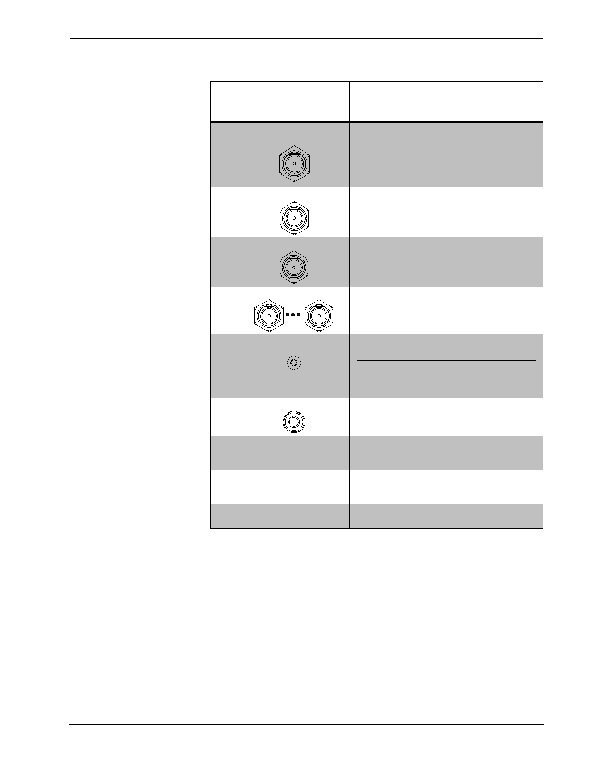
Connectors, Co n t rols, and Indicators
# CONNECTORS,
CONTROLS, AND
INDICATORS
DESCRIPTION
1 CABLE SYSTEM
INPUT
2 DATA MODEM
3 MOD INPUT
4 ZONE 1-12
5 PWR 5VDC 5A
6 TO MM-HTDR
7 ZONE
(Display and Selector
Button)
8 LENGTH/GAIN
(Display and Selector
Button)
9 FEET LED
(1) F-type coaxial, female;
Impedance: 75 Ω nominal;
Maximum Input Level: 20 dBmV;
Nominal Input Level: 0 dBmV ±5 dB
(1) F-type coaxial, female;
Impedance: 75 Ω nominal
(1) F-type coaxial, female;
Impedance: 75 Ω nominal;
Nominal Input Level: +30 dBmV
(12) F-type coaxial, female;
Bidirectional CATV distribution outputs for
use with RG6 only;
Impedance: 75 Ω nominal
(1) 3.0 mm barrel dc power jack;
5 Vdc power input (power supply included)
NOTE: Only the included power supply
should be used.
(1) 3.5 mm TRS mini-phone jack
For connection of the MM-HTDR (sold
separately) during setup
(1) Miniature push button with green LED
indicator and 2-digit display, used to select a
zone for adjustment
(1) Miniature push button with green LED
and 3-digit display, used to set the cable
length or gain for the zone selected.
(1) green LED, indicates Feet mode is
selected
(Continued on following page)
Operations & Installation Guide – DOC. 6600C MediaManifold CATV Distribution System: MM-DS-12 • 9
Page 14

MediaManifold CATV Distribution System Crestron MM-DS-12
Connectors, Co n t rols, and Indicators (Continued)
# CONNECTORS,
CONTROLS, AND
INDICATORS
DESCRIPTION
10 LENGTH/TILT
(Display and Selector
Button)
11 DB LED
12 MODE BUTTON (1) Miniature push button, selects between
13 ADJUSTMENT
BUTTONS
14 EXPANSION
* Sold separately.
(1) Miniature push button with green LED
and 3-digit display, used to set the cable
length or tilt for the zone selected.
(1) Green LED, indicates DB mode is
selected
Feet and DB modes
(2) Miniature push buttons; manually adjust
the cable length, gain, or tilt settings
(3) F-type coaxial, female
Impedance: 75 Ω nominal;
COM, OUT, and IN connections to
MM-DE-12 MediaManifold Expander;*
Maximum Cable Length: 10 feet (3 meters)
10 • MediaManifold CATV Distribution System: MM-DS-12 Operations & Installation Guide – DOC. 6600C
Page 15

Crestron MM-DS-12 MediaManifold CATV Distribution System
MM-DS-12
Screw, #8,
Qty. 4 Total
(Not Supplied)
Drill Ø 0.177 Hole,
MM-DS-12
(Center on CAEN-UMP2x2)
CAEN-UMP2x2
Keps Nut, 08-32
Qty. 4 Total
(Not Supplied)
Screw, 8-32, 3/8" L
Steel, Pan Head, Philips
Qty. 4 Total
(Not Supplied)
CAEN-2x1 Automation Enclosure
4 Places
Screw, 08-8B, 1/4"L,
Steel, Pan Head, Philips
Qty. 4 Total
Setup
Supplied Hardware
The hardware supplied with the MM-DS-12 is listed in the following table.
Supplied Hardware for the MM-DS-12
DESCRIPTION PART NUMBER QUANTITY
75 Ω Female Terminator 2017362 12
Installation
The MM-DS-12 can be mounted on a rack or on a board using the integral mo unting
flanges. Mounting hardware is not provided.
The MM-DS-12 can also be mounted in a CAEN Automation Enclosure wit h the use
of a CAEN-UMP2x2 Universal Mounting Plate for CAEN Automation Enclosures.
For more information, refer to the CAEN-UMP Installation Guide (Doc. 5981) at
www.crestron.com/manuals
.
The following diagra m s hows install ation on a board and o n a CAEN-UMP2x2.
Mounting Options for the MM-DS-12: Board Mount (Left) and CAEN-UMP2x2 (Right)
Operations & Installation Guide – DOC. 6600C MediaManifold CATV Distribution System: MM-DS-12 • 11
Page 16

MediaManifold CATV Distribution System Crestron MM-DS-12
of the unit.
paragraph. Apply power after all connections have been made.
Hardware Hookup
Ventilation
Connect the Device
The MM-DS-12 should be used in a well-ventilated area. The venting holes should
not be obstructed under any circumstances.
To prevent overheating, do not operate this product in an area that exceeds the
environmental temperature ra nge listed in the table of specifications. Consideration
must be given if installed in a close d or multi-unit rack assembly since the operating
ambient temperature of the environment may be greater than the room ambient
temperature. Contact with thermal insulating materials should be avoided on all sides
Make the necessary connections as called out in the illustration that follows this
When making connections to the MM-DS-12, consider the following:
• Use Crestron power supplies for Crestron equipment.
• Do not use any splitters to connect the cab le line to the CABLE SYSTEM
INPUT port of the MM-DS-12.
NOTE: The MM-DS-12 incorporates a high quality, passive data-grade
splitter designed for use in a calib rated system. The internal splitter
maintains a flat, 0 db feed to the system to keep the signal pure, while
providing a pass-through feed for a local cable modem. In order to deliver
pure, calibrated signals through the MediaManifold distribution system, no
splitters of any kind should be used before the MM-DS-12 system.
• Any ZONE outputs that are not used must be terminated usi ng the include d
• If the DATA MODEM output is not connected, it must be terminated using
• Each ZONE output is intended to feed a single television, cable box, or
12 • MediaManifold CATV Distribution System: MM-DS-12 Operations & Installation Guide – DOC. 6600C
terminators.
the included terminator.
other receiver connected at the end of a homerun cable. The use of splitters
or taps is not recommended. This product is for use with RG6 cable only.
Page 17

Crestron MM-DS-12 MediaManifold CATV Distribution System
CABLE SYSTEM INPUT:
From Cable Company
DATA MODEM:
To Cable Modem or
Equipment for Digital
Phone Service
(Terminate If Not Used)
MOD INPUT:
From Modulated
Video Source
ZONE 1:
Output to Zone 1
(Terminate If Not Used)
ZONE 2:
Output to Zone 2
(Terminate If Not Used)
ZONE 3:
Output to Zone 3
(Terminate If Not Used)
ZONE 4:
Output to Zone 4
(Terminate If Not Used)
ZONE 5:
Output to Zone 5
(Terminate If Not Used)
ZONE 6:
Output to Zone 6
(Terminate If Not Used)
COM:
To MM-DE-12
OUT:
To MM-DE-12
IN:
From MM-DE-12
ZONE 7:
Output to Zone 7
(Terminate If Not Used)
ZONE 8:
Output to Zone 8
(Terminate If Not Used)
ZONE 9:
Output to Zone 9
(Terminate If Not Used)
ZONE 10:
Output to Zone 10
(Terminate If Not Used)
ZONE 11:
Output to Zone 11
(Terminate If Not Used)
ZONE 12:
Output to Zone 12
(Terminate If Not Used)
PWR 5VDC 5A:
From Included
Power Supply
TO MM-HTDR: To
MM-HTDR MediaManifold
Cable Analyzer
(Sold Seperately)
or a cable up to 10 feet in length (not included).
Hardware Connections for t he MM-DS-12
Connect the MM-DE-12
(Optional)
NOTE: The MM-DS-12 does not enhance or modify the signals to the DATA
MODEM output.
If an MM-DE-12 MediaManifold Expander is to be used, make the following
connections:
• Connect the EXPANSION-OUT port on the MM-DS-12 to the
EXPANSION-IN port on the MM-DE-12. Use the 1 1/2 foot (0.5 m) cable
included with the MM-DE-12 or a cable up to 10 feet in length (not
included).
• Connect the EXPANSION-IN port on the MM-DS-12 to the
EXPANSION-OUT port on the MM-DE-12. Use the 1 1/2 foot (0.5 m)
cable included with the MM-DE-12 or a cable up to 10 feet in length (not
included).
• Connect the COM port on the MM-DS-12 to the COM port on the
MM-DE-12. Use the 1 1/2 foot (0.5 m) cable included with the MM-DE-12
Operations & Installation Guide – DOC. 6600C MediaManifold CATV Distribution System: MM-DS-12 • 13
Page 18

MediaManifold CATV Distribution System Crestron MM-DS-12
6601) at www.crestron.com/manuals.
For more information refer to the MM-DE-12 Operations & Installation Guide ( D oc.
14 • MediaManifold CATV Distribution System: MM-DS-12 Operations & Installation Guide – DOC. 6600C
Page 19

Crestron MM-DS-12 MediaManifold CATV Distribution System
Feet mode.
DB mode.
zone’s settings for cable length or gain and tilt is displayed.
3. Press the GAIN or TILT button. The GAIN and TILT LEDs illuminate.
Operation
The MM-DS-12 can optimize 12 zones. If a MM-DE-12 MediaManifold Expander is
connected, an additional 12 zones can be optimized from the MM-DS-12 control
panel.
Operating Modes
Each zone of the MM-DS-12 can be calibrated using the length of cable or gain and
tilt settings. When a zone is calibr a te d using cable length, the display units are
measured in feet. When a zone is calibrated using gain and tilt, the display units are
measured in decibels (dB). The selected unit of measure is indicated on the display.
Feet Mode
DB Mode
Select the Zone
When a zone is operating in Feet mode, the selected zone is configured with a
specific length setting that is measured in feet. The selected zone’s cable length
setting is displayed and the cable length can be adjusted with the j or k buttons.
Zones that are set in Feet mode are indicated by the FEET LED. To switch a zone to
Feet mode, press and release the buttons labeled DEFAULT CAL (the LENGTH
and TILT buttons pressed together). The FEET LED illuminates when a zone is in
When a zone is operating in DB mode, the selected zone is configured with specific
gain and tilt settings that are measured in decibels. The selected zone’s gain and tilt
settings are displayed and can be adjusted with the j or k buttons.
Zones that are set in DB mode are indicated by the DB LED. To switch a zone to DB
mode, press and release the DB button. The DB LED illuminates when a zone is in
Configure a Zone
When confi guring a zone , perform the following steps:
1. Select the zone.
2. Set the cable length.
3. Set gain and tilt (to be used only if fine tuning is required).
Before making any changes to the cable length, gain, or tilt, a zone must be selected.
The selected zone is displayed on the left side of the display. Pe rform the following
to select a zone:
1. Press the ZONE button.
2. Press the j or k buttons to change the zone number on the display. Each
Set Cable Length
Operations & Installation Guide – DOC. 6600C MediaManifold CATV Distribution System: MM-DS-12 • 15
A zone’s cable length can be set automatically with the MM-HTDR MediaManifold
Cable Analyzer (sold separately) or manuall y wit h the fr o nt p ane l. For instructions
on setting the cable length automatically, refer to the MM-HTDR Operations Guide
(Doc. 6602) at www.crestron.com/manuals
Perform the following to set the cable length manually:
1. Select the zone to be configured as described above.
2. Verify that the FEET LED is lit. If the zone is in DB mode (DB LED is lit),
press the buttons labeled DEFAULT CAL (the LENGTH and TILT
buttons pressed together) to return to Feet mode.
.
Page 20

MediaManifold CATV Distribution System Crestron MM-DS-12
three seconds after the last button press.
4. Press the j or k buttons to change the cable length shown on the display.
NOTE: Any zone that is not used must be set to 10 feet (3 meters). The
zone connector must also be terminated using the included terminators.
After setting the cable length, the displayed value is saved approximately
Set the Gain and Tilt
(Advanced Function)
Given a cab l e length, a zo ne's gain and tilt are set automatically. The gain and tilt
settings can be adjusted further to optimize the signal.
NOTE: Gain and tilt should be adjusted with a cable box’s diagnostic feature.
Perform the following to set the gain:
1. Select a zone as described on page 15.
2. Verify that the DB LED is lit. If it is not lit, select DB mode as described in
“Operating Modes” on page 15.
3. Press the button located under the displayed GAIN value.
4. Press the j or k buttons to change the gain value shown on the display.
After setting the gain, t he displayed value is saved approximately three
seconds after the last button press.
NOTE: To revert to the last specified cable length for this zone, press and
release the buttons labeled DEFAULT CAL. The FEET LED lights.
Perform the following to set the tilt:
1. Select a zone as described on page 15.
2. Verify that the DB LED is lit. If it is not lit, select the DB mode as
described in “Operating Modes” on page 15.
3. Press the button located under the displayed TILT value.
4. Press the j or k buttons to change the t i lt value shown on the dis play.
After setting the tilt, the displayed value is saved approximately three
seconds after the last button press.
NOTE: To revert to the last specified cable length, press and release the
buttons labeled DEFAULT CAL (the LENGTH and TILT buttons
pressed together). The FEET LED lights. Changes made in DB mode are
discarded.
Restore Factory Settings
To restore the factory settings, press and hold the MODE button and then pre s s the
ZONE b u tton. The cable length value for every zone is set to 10 feet (3 meters). The
corresponding ga in and tilt values (0 dB and 0 dB, respectively) are also set.
16 • MediaManifold CATV Distribution System: MM-DS-12 Operations & Installation Guide – DOC. 6600C
Page 21

Crestron MM-DS-12 MediaManifold CATV Distribution System
Problem Solving
Troubleshooting
The following table provides co rrective action for possible trouble situations. If
further assistance is required, please contact a Crestron customer service
representative.
MM-DS-12 Troubleshooting
TROUBLE POSSIBLE CAUSE(S) CORRECTIVE ACTION
Device does not
function.
The picture has
poor quality.
Certain TV
channels have
poor picture
quality.
Cable box or
cable modem is
not receiving
signal.
Device is not receiving
power from a Crestron
power source.
Cables are not securely
connected.
Cable run is not properly
calibrated.
Low signal strength. Increase the gain setting to
There is too much signal
loss at low end of the
frequency spectrum.
There is a short or open
in circuit path.
The cable box or cable
modem is not working.
Use the provided Crestron
power source. Verify
connections.
Properly connect all cables.
Verify setting for cable
length.
compensate for signal loss.
Raise the tilt setting to
accommodate for signal
loss.
Verify cabling.
Contact the local cable
operator for repair.
Reference Documents
All documents mentioned in this gu ide are available at www.crestron.com/manuals.
List of Related Reference Documents
DOCUMENT TITLE
CAEN-UMP Universal Mounting Plates for CAEN Automation Enclosures
MM-DE-12 MediaManifold Expander
MM-HTDR MediaManifold Cable Analyzer
Further Inquiries
To locate specific information or resolve questions after reviewing this guide,
contact Crestron's True Blue Support at 1-888-CRESTRON [1-888-273-7876] or, for
assistance within a particular geographic region, refer to the listing of Crestron
worldwide offices at www.crestron.com/offices
To post a question about Crestron products, log onto Crestron’s Online Help at
www.crestron.com/onlinehelp
. First-time users must establish a user account to fully
benefit from all available features.
Operations & Installation Guide – DOC. 6600C MediaManifold CATV Distribution System: MM-DS-12 • 17
.
Page 22

MediaManifold CATV Distribution System Crestron MM-DS-12
Future Updates
As Crestron improves functions, adds new features, and extends the capabilities of
the MM-DS-12, additional information may be made available as manual updates.
These updates are solely electronic and serve as intermediary supplements prior to
the release of a complete technical documentation revision.
Check the Crestron website periodically for manual update availability and its
relevance. Updates are identified as an “Addendum” in the Download column.
18 • MediaManifold CATV Distribution System: MM-DS-12 Operations & Installation Guide – DOC. 6600C
Page 23

Crestron MM-DS-12 MediaManifold CATV Distribution System
Return and Warranty Policies
Merchandise Returns / Re pa ir Ser vi c e
1. No merchandise may be returned for credit, exchange or service without prior authorization from
Crestron. To obtain warranty service for Crestron products, contact an authorized Crestron dealer.
Only authorized Crestron dealers may contact the factory and request an RMA (Return
Merchandise Authorization) number. Enclose a note specifying the nature of the problem, name
and phone number of contact person, RMA number and return address.
2. Products may be re turned for cred it, exchange or service with a Crestron Return Merchandise
Authorization (RMA) number. Authorized returns must be shipped freight prepaid to Crestron,
6 Volvo Drive, Rockleigh, N.J. or its authorized subsidiaries, with RMA number clearly marked
on the outside of all cartons. Shipments arriving freight collect or without an RMA number shall
be subject to refusal. Crestron reserves the right in its sole and absolute discretion to charge a 15%
restocking fee plus shipping costs on any products returned with a n R MA.
3. Return freight charges following repair of items under warranty shall be paid by Crestron,
shipping by standard ground carrier. In the event repairs are found to be non-warranty, return
freight costs shall be paid by the purchaser.
CRESTRON Limited Warranty
Crestron Electronics, Inc. warrants its products to be free from manufacturing defects in materials and
workmanship under normal use for a period of three (3) years from the date of purchase from Crestron,
with the following exceptions: d i s k drives and any other moving or rotating mechanical parts, pan/tilt head s
and power supplies are covered for a period of one (1) year; touch screen display and overlay components
are covered for 90 days; batteries and incandescent lamps are not covered.
This warranty extends to products purchased directly from Crestron or an authorized Crestron dealer.
Purchasers should inquire of the dealer regarding the nature and extent of the dealer's warranty, if any.
Crestron shall not be liable to honor the te rms of this warranty if the product has been used in any
application other than that for which it was intended or if it has been subj e c te d to misuse, accidental
damage, modification or improper installation procedures. Furthermore, this warranty does not cover any
product that has had the serial number altered, defaced or removed.
This warranty shall be the sole and exclusive remedy to the original pur chaser. In no event shall Crestron
be liable for incidental or consequential damages of any kind (property or economic damages inclusive)
arising from the sale or use of this eq uipment. Crestron is not liable for any claim made by a third party or
made by the purchaser for a third party.
Crestron shall, at its option, repair or replace any product found defective, without charge for parts or labor.
Repaired or replaced equipment and parts supplied under this warranty shall be covered only by the
unexpired portion of the warranty.
Except as expressly set forth in this warranty, Crestron makes no other warranties, expressed or implied,
nor authorizes any other party to offer any warranty, including any implied warranties of merchantability or
fitness for a particular purpose. A ny implied warranties that may be imposed by law are limited to the terms
of this limited warranty. This warranty statement supersedes all previous warranties.
Operations & Installation Guide – DOC. 6600C MediaManifold CATV Distribution System: MM-DS-12 • 19
Page 24

Crestron Electronics, Inc. Operations & Installation Guide – DOC. 6600C
15 Volvo Drive Rockleigh, NJ 07647 (2018378)
Tel: 888.CRESTRON 03.14
Fax: 201.767.7576 Specifications subject to
www.crestron.com change without notice.
 Loading...