

Page 1

Crestron MM-DE-12
MediaManifold™ Expander
Operations & Installation Guide
Page 2

This document was prepared and written by the Technical Documentation department at:
Crestron Electronics, Inc.
15 Volvo Drive
Rockleigh, NJ 07647
1-888-CRESTRON
All brand names, product names and trademarks are the property of their respective owners.
©2007 Crestron Electronics, Inc.
Page 3

Crestron MM-DE-12 MediaManifold™ Expander
Contents
MediaManifold™ Expander: MM-DE-12 1
Introduction ...............................................................................................................................1
Features and Functions................................................................................................ 1
Applications.................................................................................................................2
Specifications ..............................................................................................................3
Physical Description.................................................................................................... 4
Industry Compliance ...................................................................................................7
Setup .......................................................................................................................................... 8
Supplied Hardware...................................................................................................... 8
Installation................................................................................................................... 8
Hardware Hookup .......................................................................................................9
Operation .................................................................................................................................12
Problem Solving ......................................................................................................................13
Troubleshooting......................................................................................................... 13
Reference Documents................................................................................................13
Further Inquiries........................................................................................................ 14
Future Updates ..........................................................................................................14
Return and Warranty Policies.................................................................................................. 15
Merchandise Returns / Repair Service ......................................................................15
CRESTRON Limited Warranty.................................................................................15
Operations & Installation Guide – DOC. 6601A Contents • i
Page 4

Page 5

Crestron MM-DE-12 MediaManifold™ Expander
MediaManifold™ Expander:
MM-DE-12
Introduction
The MM-DE-12 is a 12-zone expander for the MM-DS-12 MediaManifold High-
Definition CATV Distribution System. Adding the MM-DE-12 Expander to the
MM-DS-12 provides a total of 24 zone outputs. Each zone includes independent gain
and tilt adjustments, and supports up to 300 feet of homerun RG6 coaxial cable
feeding a single television or set-top box. Complete setup of the MM-DE-12 is
facilitated through the MM-DS-12 front panel.
The MM-DE-12 is intended to mount to a wall surface beside or beneath the
MM-DS-12, and connects to the MM-DS-12 using three short ‘F’ cables (included).
An additional input is provided for an external modulator to enable signals from
security cameras and other video sources to be combined and distributed along with
the main cable TV channels.
NOTE: The MM-DE-12 is not designed for use with MoCA-based multimedia
networks or devices.
Features and Functions
• 12-zone MediaManifold™ expander, requires MM-DS-12 CATV
Distribution System (sold separately)
• High-power, high-headroom, low-noise, and low-distortion
• Supports bidirectional RG6 cable runs up to 300 feet each
• Individual gain and tilt adjustments per zone (from MM-DS-12)
• Automatic setup using MM-HTDR Cable Analyzer (sold separately)
• Compact surface wall-mount design
Operations & Installation Guide – DOC. 6601A MediaManifold™ Expander: MM-DE-12 • 1
Page 6

MediaManifold™ Expander Crestron MM-DE-12
Applications
The following diagram shows an MM-DE-12 in a residential application.
MM-DE-12 in a Residential Application
2 • MediaManifold™ Expander: MM-DE-12 Operations & Installation Guide – DOC. 6601A
Page 7

Crestron MM-DE-12 MediaManifold™ Expander
Specifications
Specifications for the MM-DE-12 are listed in the following table.
MM-DE-12 Specifications
SPECIFICATION DETAILS
Input Channels 1 expansion line + 1 modulator input
Output Channels 12 television
Forward Bandwidth 54 MHz to 1 GHz
Reverse Bandwidth 5 MHz to 42 MHz
Minimum Output Cable Length 5 feet (1.5 meters)
Maximum Output Cable Length 300 feet (91 meters)
Gain 23 dB, 20 dB gain for tilt
Isolation < 45 dB
Power Requirements 5 Amps @ 5 Volts, DC regulated;
Powered by PW-0550R, 120 Volts AC,
60 Hz (included)
Enclosure
Environmental
Temperature 41º to 104ºF (5º to 40ºC)
Humidity
Heat Dissipation
Dimensions
Height 11.05 in (28.07 cm)
Width 10.42 in (26.47 cm)
Depth 2.54 in (6.45 cm)
Weight 5.7 lbs (2.6 kg)
Available Accessories
MM-DS-12
MM-HTDR
CAEN
CAEN-UMP
Chromium-plated aluminum with black
powder-coated steel end panels and
polycarbonate label overlay, surfacemount with integral heat-sinks and (2)
mounting flanges
10% to 90% RH (non-condensing)
68 BTU/Hr
MediaManifold CATV Distribution System
(required)
MediaManifold Cable Analyzer
Automation Enclosure
Universal Mounting Plates
Operations & Installation Guide – DOC. 6601A MediaManifold™ Expander: MM-DE-12 • 3
Page 8

MediaManifold™ Expander Crestron MM-DE-12
Physical Description
This section provides information on the connections and indicators available on
your MM-DE-12.
MM-DE-12 Physical View
4 • MediaManifold™ Expander: MM-DE-12 Operations & Installation Guide – DOC. 6601A
Page 9

Crestron MM-DE-12 MediaManifold™ Expander
MM-DE-12 Overall Dimensions
2.54 in
(6.45 cm)
10.42 in
(26.47 cm)
9.87 in
(25.07 cm)
Ø0.19 in (0.48 cm),
4 Places
11.05 in
(28.07 cm)
7.96 in
(20.22 cm)
10.70 in
(27.18 cm)
1.54 in
(3.92 cm)
Operations & Installation Guide – DOC. 6601A MediaManifold™ Expander: MM-DE-12 • 5
Page 10

MediaManifold™ Expander Crestron MM-DE-12
MM-DE-12 Ports and Buttons
3 5
4
1
2
Connectors, Controls & Indicators
# CONNECTORS,
6
DESCRIPTION
CONTROLS &
INDICATORS
1
2
(Continued on following page)
6 • MediaManifold™ Expander: MM-DE-12 Operations & Installation Guide – DOC. 6601A
MOD INPUT
ZONE OUTPUTS 13-18 (6) Female F-type coaxial connectors
(1) Female F-type coaxial connector
receives signals from a video modulator
(i.e. nanny camera). For use with RG6
cable only.
Nominal Input: +30 dBmV
Nominal Impedance: 75 ohms
transmit cable signals to up to six zones (13
through 18). For use with RG6 cable only.
Maximum Gain: 23 dB
Nominal Impedance: 75 ohms
Page 11

Crestron MM-DE-12 MediaManifold™ Expander
Connectors, Controls & Indicators (Continued)
# CONNECTORS,
CONTROLS &
INDICATORS
3
4 PWR LED
5
ZONE OUTPUTS 19-24 (6) Female F-type coaxial connectors
6
PWR
EXPANSION
DESCRIPTION
(1) 3.0 mm barrel DC power jack. This port is
used to connect the included power supply
(PW-0550R).
Power Input: 5 VDC, 5 A
NOTE: Only the included power supply
should be used.
(1) green LED, indicates 5 Volts DC power
supplied from power supply
(3) Female F-type coaxial connectors for
connecting MM-DS-12 MediaManifold CATV
Distribution System.
Nominal Impedance: 75 ohms
Maximum Cable Length: 10 feet (3 meters)
(3) 1.5-foot connecting cables included
transmit cable signals to up to six zones (19
through 24). For use with RG6 cable only.
Maximum Gain: 23 dB
Nominal Impedance: 75 ohms
Industry Compliance
NOTE: This device complies with part 15 of the FCC rules. Operation is subject to
the following two conditions: (1) this device may not cause harmful interference and
(2) this device must accept any interference received, including interference that may
cause undesired operation.
This equipment has been tested and found to comply with the limits for a Class B
digital device, pursuant to part 15 of the FCC Rules. These limits are designed to
provide reasonable protection against harmful interference in a residential
installation. This equipment generates, uses and can radiate radio frequency energy
and if not installed and used in accordance with the instructions, may cause harmful
interference to radio communications. However, there is no guarantee that
interference will not occur in a particular installation. If this equipment does cause
harmful interference to radio or television reception, which can be determined by
turning the equipment off and on, the user is encouraged to try to correct the
interference by one or more of the following measures:
Reorient or relocate the receiving antenna.
Increase the separation between the equipment and receiver.
Connect the equipment into an outlet on a circuit different from that to
which the receiver is connected.
Consult the dealer or an experienced radio/TV technician for help.
Operations & Installation Guide – DOC. 6601A MediaManifold™ Expander: MM-DE-12 • 7
Page 12

MediaManifold™ Expander Crestron MM-DE-12
Setup
Supplied Hardware
The hardware supplied with the MM-DE-12 is listed in the following table.
Supplied Hardware for the MM-DE-12
DESCRIPTION PART NUMBER QUANTITY
75 Ohm Female Terminator 2017362 12
Cable Assy, RG6, F Male to F Male, 18” L 2019405 3
Installation
The MM-DE-12 can be mounted on a rack or on a board using the integral mounting
flanges as shown in the following diagram. Mounting hardware is not provided.
Mounting the MM-DE-12 to a Board
MM-DE-12
SCREW, #8,
QTY. 4 TOTAL
(NOT SUPPLIED)
MM-DS-12
8 • MediaManifold™ Expander: MM-DE-12 Operations & Installation Guide – DOC. 6601A
Page 13

Crestron MM-DE-12 MediaManifold™ Expander
The MM-DE-12 can also be mounted in a CAEN Automation Enclosure with the use
of a CAEN-UMP2x2 Universal Mounting Plate for CAEN Automation Enclosures.
The installation is shown in the following diagram with a MM-DS-12 installed in the
same enclosure.
Mounting the MM-DE-12 to a CAEN-UMP2x2
CAEN-4x1
CAEN-UMP2x2
MM-DE-12
(CENTER ON CAEN-UMP2x2)
MOUNTED ON CAEN-UMP2x2
KEPS NUT, 08-32
QTY. 4 TOTAL
(NOT SUPPLIED)
SCREW, 8-32, 3/8"L
STEEL, PAN HEAD, PHILIPS
QTY. 4 TOTAL
(NOT SUPPLIED)
MM-DS-12
DRILL Ø 0.177 HOLE
4 PLACES
SCREW, 08-8B, 1/4"l,
STEEL, PAN HEAD, PHILIPS
QTY. 4 TOTAL
For more information, refer to the latest version of the CAEN-UMP Installation
Guide (Doc. 5981) which is available from the Crestron website
(www.crestron.com/manuals
).
Hardware Hookup
Ventilation
Operations & Installation Guide – DOC. 6601A MediaManifold™ Expander: MM-DE-12 • 9
To prevent overheating, do not operate this product in an area that exceeds the
environmental temperature range listed in the table of specifications. Consideration
must be given if installed in a closed or multi-unit rack assembly since the operating
ambient temperature of the rack environment may be greater than the room ambient.
Contact with thermal insulating materials should be avoided on all sides of the unit.
Page 14
MediaManifold™ Expander Crestron MM-DE-12
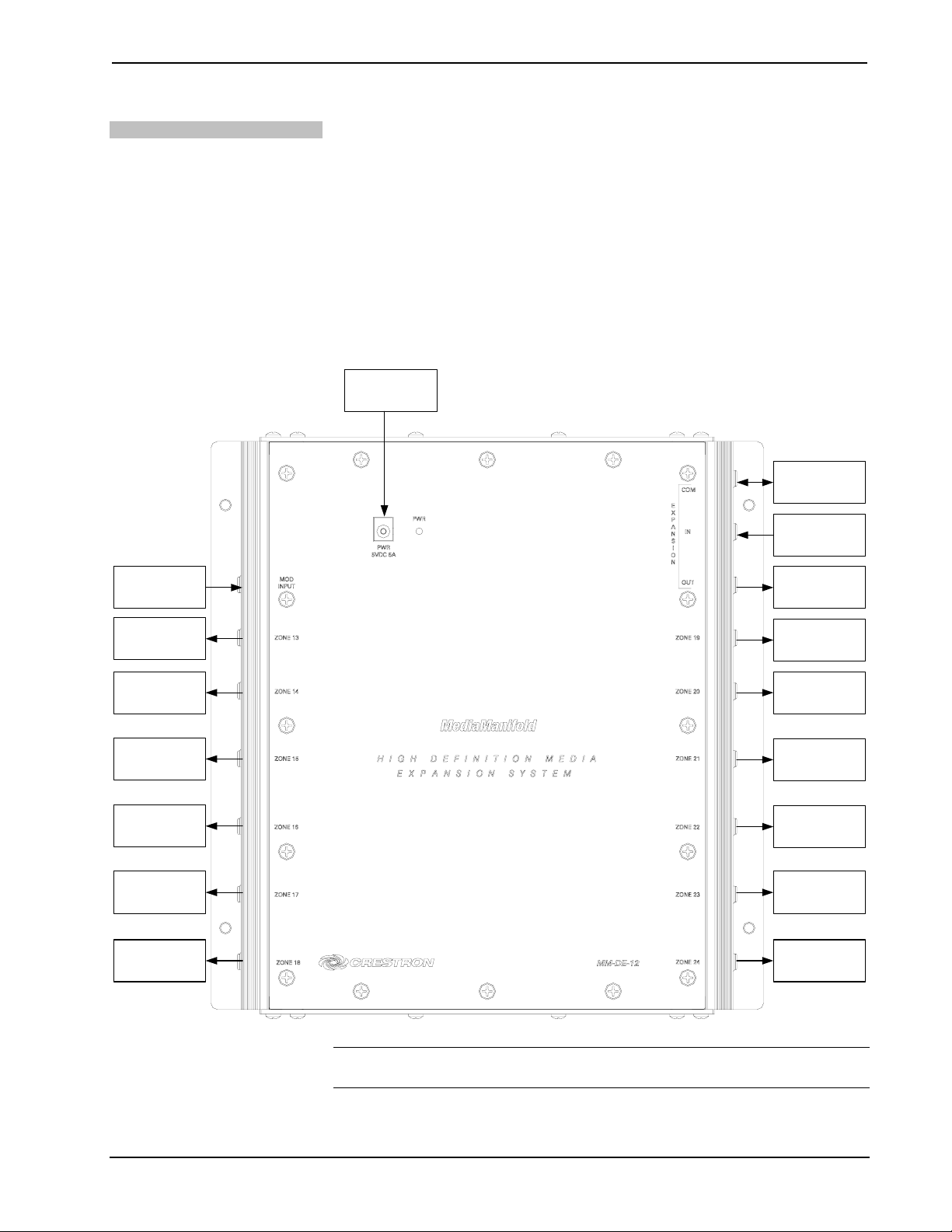
Connect the Device
Make the necessary connections as called out in the illustration that follows this
paragraph. Apply power after all connections have been made.
When making connections to the MM-DE-12, consider the following:
Hardware Connections for the MM-DE-12
MOD INPUT:
FROM MODULATED
VIDEO SOURCE
• Use Crestron power supplies for Crestron equipment.
• The included power cord cannot be extended.
• Each ZONE output is intended to feed a single television, cable box, or
other receiver connected at the end of a homerun cable. The use of splitters
or taps is not recommended. This product is for use with RG6 cable only.
POWER:
FROM INCLUDED
POWER SUPPLY
COM:
TO MM-DS-12
IN:
FROM MM-DS-12
OUT:
TO MM-DS-12
ZONE 13:
OUTPUT TO ZONE 1 3.
TERMINATE IF NOT
USED.
ZONE 14:
OUTPUT TO ZONE 1 4.
TERMINATE IF NOT
USED.
ZONE 15:
OUTPUT TO ZONE 1 5.
TERMINATE IF NOT
USED.
ZONE 16:
OUTPUT TO ZONE 1 6.
TERMINATE IF NOT
USED.
ZONE 17:
OUTPUT TO ZONE 1 7.
TERMINATE IF NOT
USED.
ZONE 18:
OUTPUT TO ZONE 1 8.
TERMINATE IF NOT
USED.
ZONE 19:
OUTPUT TO ZONE 19.
TERMINATE IF NOT
USED.
ZONE 20:
OUTPUT TO ZONE 20.
TERMINATE IF NOT
USED.
ZONE 21:
OUTPUT TO ZONE 21.
TERMINATE IF NOT
USED.
ZONE 22:
OUTPUT TO ZONE 22.
TERMINATE IF NOT
USED.
ZONE 23:
OUTPUT TO ZONE 23.
TERMINATE IF NOT
USED.
ZONE 24:
OUTPUT TO ZONE 24.
TERMINATE IF NOT
USED.
NOTE: Any ZONE outputs that are not used must be terminated using the included
terminators.
10 • MediaManifold™ Expander: MM-DE-12 Operations & Installation Guide – DOC. 6601A
Page 15

Crestron MM-DE-12 MediaManifold™ Expander
Connect the MM-DS-12
The following connections must be made to connect to the MM-DS-12:
• Connect the COM port on the MM-DE-12 to the COM port on the
MM-DS-12 MediaManifold CATV Distribution System. Use the 1.5-foot
length cable included with the MM-DE-12 or a cable up to 10 feet in length
(not included).
• Connect the EXPANSION-IN port on the MM-DE-12 to the
EXPANSION-OUT port on the MM-DS-12 MediaManifold CATV
Distribution System. Use the 1.5-foot length cable included with the
MM-DE-12 or a cable up to 10 feet in length (not included).
• Connect the EXPANSION-OUT port on the MM-DE-12 to the
EXPANSION-IN port on the MM-DS-12 MediaManifold CATV
Distribution System. Use the 1.5-foot length cable included with the
MM-DE-12 or a cable up to 10 feet in length (not included).
For more information, refer to the latest version of the MM-DS-12 Operations &
Installation Guide (Doc. 6600) which is available for download from the Crestron
website.
Operations & Installation Guide – DOC. 6601A MediaManifold™ Expander: MM-DE-12 • 11
Page 16

MediaManifold™ Expander Crestron MM-DE-12
Operation
Settings for zones connected to the MM-DE-12 are controlled by the MM-DS-12
MediaManifold CATV Distribution System. For instructions, refer to the latest
version of the MM-DS-12 Operations & Installation Guide (Doc. 6600) which is
available for download from the Crestron website.
12 • MediaManifold™ Expander: MM-DE-12 Operations & Installation Guide – DOC. 6601A
Page 17
Crestron MM-DE-12 MediaManifold™ Expander
Problem Solving
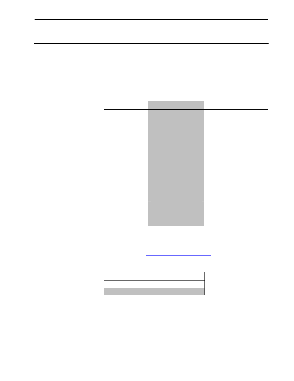
Troubleshooting
The following table provides corrective action for possible trouble situations. If
further assistance is required, please contact a Crestron customer service
representative.
MM-DE-12 Troubleshooting
TROUBLE POSSIBLE CAUSE(S) CORRECTIVE ACTION
Device does not
function.
Poor picture.
Certain TV
channels have
poor picture.
Cable box is not
receiving signal.
Device is not receiving
power from a Crestron
power source.
Cables are not securely
connected.
Cable run is not properly
calibrated.
Low signal strength.
Too much signal loss at
low end of the frequency
spectrum.
Short or open in circuit
path.
Cable box is not
working.
Use the provided Crestron
power source. Verify
connections.
Properly connect all cables.
Verify setting for cable
length.
Increase the gain setting on
the MM-DS-12 CATV
Distribution System to
compensate for signal loss.
Raise the tilt setting on the
MM-DS-12 CATV
Distribution System to
accommodate for signal
loss.
Verify cabling.
Contact the local cable
operator for repair.
Reference Documents
The latest version of all documents mentioned within the guide can be obtained from
the Crestron website (http://www.crestron.com/manuals
of product manuals arranged in alphabetical order by model number.
). This link will provide a list
List of Related Reference Documents
DOCUMENT TITLE
CAEN-UMP Installation Guide
MM-DS-12 Operations & Installation Guide
Operations & Installation Guide – DOC. 6601A MediaManifold™ Expander: MM-DE-12 • 13
Page 18

MediaManifold™ Expander Crestron MM-DE-12
Further Inquiries
If you cannot locate specific information or have questions after reviewing this
guide, please take advantage of Crestron's award winning customer service team by
calling the Crestron corporate headquarters at 1-888-CRESTRON [1-888-273-7876].
For assistance in your local time zone, refer to the Crestron website
(http://www.crestron.com/offices) for a listing of Crestron worldwide offices.
You can also log onto the online help section of the Crestron website
(http://www.crestron.com/onlinehelp
First-time users will need to establish a user account to fully benefit from all
available features.
) to ask questions about Crestron products.
Future Updates
As Crestron improves functions, adds new features and extends the capabilities of
the MM-DE-12, additional information may be made available as manual updates.
These updates are solely electronic and serve as intermediary supplements prior to
the release of a complete technical documentation revision.
Check the Crestron website periodically for manual update availability and its
relevance. Updates are identified as an “Addendum” in the Download column.
14 • MediaManifold™ Expander: MM-DE-12 Operations & Installation Guide – DOC. 6601A
Page 19

Crestron MM-DE-12 MediaManifold™ Expander
Return and Warranty Policies
Merchandise Returns / Repair Service
1. No merchandise may be returned for credit, exchange or service without prior authorization
from CRESTRON. To obtain warranty service for CRESTRON products, contact an
authorized CRESTRON dealer. Only authorized CRESTRON dealers may contact the factory
and request an RMA (Return Merchandise Authorization) number. Enclose a note specifying
the nature of the problem, name and phone number of contact person, RMA number and
return address.
2. Products may be returned for credit, exchange or service with a CRESTRON Return
Merchandise Authorization (RMA) number. Authorized returns must be shipped freight
prepaid to CRESTRON, 6 Volvo Drive, Rockleigh, N.J. or its authorized subsidiaries, with
RMA number clearly marked on the outside of all cartons. Shipments arriving freight collect
or without an RMA number shall be subject to refusal. CRESTRON reserves the right in its
sole and absolute discretion to charge a 15% restocking fee plus shipping costs on any
products returned with an RMA.
3. Return freight charges following repair of items under warranty shall be paid by CRESTRON,
shipping by standard ground carrier. In the event repairs are found to be non-warranty, return
freight costs shall be paid by the purchaser.
CRESTRON Limited Warranty
CRESTRON ELECTRONICS, Inc. warrants its products to be free from manufacturing defects in materials
and workmanship under normal use for a period of three (3) years from the date of purchase from
CRESTRON, with the following exceptions: disk drives and any other moving or rotating mechanical
parts, pan/tilt heads and power supplies are covered for a period of one (1) year; touchscreen display and
overlay components are covered for 90 days; batteries and incandescent lamps are not covered.
This warranty extends to products purchased directly from CRESTRON or an authorized CRESTRON
dealer. Purchasers should inquire of the dealer regarding the nature and extent of the dealer's warranty, if
any.
CRESTRON shall not be liable to honor the terms of this warranty if the product has been used in any
application other than that for which it was intended or if it has been subjected to misuse, accidental
damage, modification or improper installation procedures. Furthermore, this warranty does not cover any
product that has had the serial number altered, defaced or removed.
This warranty shall be the sole and exclusive remedy to the original purchaser. In no event shall
CRESTRON be liable for incidental or consequential damages of any kind (property or economic damages
inclusive) arising from the sale or use of this equipment. CRESTRON is not liable for any claim made by a
third party or made by the purchaser for a third party.
CRESTRON shall, at its option, repair or replace any product found defective, without charge for parts or
labor. Repaired or replaced equipment and parts supplied under this warranty shall be covered only by the
unexpired portion of the warranty.
Except as expressly set forth in this warranty, CRESTRON makes no other warranties, expressed or
implied, nor authorizes any other party to offer any warranty, including any implied warranties of
merchantability or fitness for a particular purpose. Any implied warranties that may be imposed by law are
limited to the terms of this limited warranty. This warranty statement supersedes all previous warranties.
Trademark Information
All brand names, product names and trademarks are the sole property of their respective owners. Windows is a registered trademark
of Microsoft Corporation. Windows95/98/Me/XP/Vista and WindowsNT/2000 are trademarks of Microsoft Corporation.
Operations & Installation Guide – DOC. 6601A MediaManifold™ Expander: MM-DE-12 • 15
Page 20

Crestron Electronics, Inc. Operations & Installation Guide – DOC. 6601A
15 Volvo Drive Rockleigh, NJ 07647 (2018379)
Tel: 888.CRESTRON 10.07
Fax: 201.767.7576 Specifications subject to
www.crestron.com change without notice.
 Loading...