

Page 1

AM-200/AM-300
AirMedia® 2.0 Presentation
Systems
Product Manual
Crestron Electronics, Inc.
Page 2
The product warranty can be found at www.crestron.com/legal/sales-terms-conditions-warranties.
The specific patents that cover Crestron products are listed at www.crestron.com/legal/patents.
Certain Crestron products contain open source software. For specific information, visit www.crestron.com/legal/open-
source-software.
Crestron, the Crestron logo, Crestron AirBoard, AirMedia, .AV Framework, Crestron Connected, Crestron Fusion, Crestron
Studio, Crestron Toolbox, Crestron XiO Cloud, DigitalMedia, DM, Pinpoint, and Zūm are either trademarks or registered
trademarks of Crestron Electronics, Inc. in the United States and/or other countries. App Store, iPad, iPhone, iTunes, and
Mac are either trademarks or registered trademarks of Apple, Inc. in the United States and/or other countries. Appspace is
either a trademark or a registered trademark of Appspace Inc. in the United States and/or other countries. Android, Chrome
OS, Google Play, and YouTube are either trademarks or registered trademarks of Google, Inc. in the United States and/or
other countries. iOS is either a trademark or registered trademark of Cisco Systems, Inc. in the United States and/or other
countries. HDMI and the HDMI logo are either trademarks or registered trademarks of HDMI Licensing LLC in the United
States and/or other countries. Microsoft, Active Directory, Microsoft Exchange Server, Outlook, PowerShell, and Windows
are either trademarks or registered trademarks of Microsoft Corporation in the United States and/or other countries. Other
trademarks, registered trademarks, and trade names may be used in this document to refer to either the entities claiming
the marks and names or their products. Crestron disclaims any proprietary interest in the marks and names of others.
Crestron is not responsible for errors in typography or photography.
This document was written by the Technical Publications department at Crestron.
©2019 Crestron Electronics, Inc.
Page 3

Contents
Introduction ................................................................................................................................... 1
Requirements ............................................................................................................................... 3
Administrator.............................................................................................................................................. 3
Operating Environment ............................................................................................................................ 4
Configuration ............................................................................................................................... 5
Requirements .............................................................................................................................................. 5
Connect to the Device ............................................................................................................................... 5
Log Out from the Device .......................................................................................................................... 6
Configure the Device ................................................................................................................................. 7
HDMI INPUT ......................................................................................................................................... 7
DM IN (AM-300 Only) ........................................................................................................................ 8
HDMI OUTPUT ..................................................................................................................................... 9
NETWORK .......................................................................................................................................... 10
DEVICE ................................................................................................................................................ 16
APPSPACE .......................................................................................................................................... 25
AMPS ................................................................................................................................................... 27
AirMedia .............................................................................................................................................. 41
Crestron AirBoard ............................................................................................................................. 42
Enterprise Deployment Options ............................................................................................. 45
Crestron XiO Cloud Service ................................................................................................................... 45
Claim a Single Device ....................................................................................................................... 45
Claim Multiple Devices ..................................................................................................................... 46
Crestron Deployment Tool for PowerShell® Software .............................................................. 47
Operation .................................................................................................................................... 48
Connect a Source .................................................................................................................................... 48
Touch Screen Operation ........................................................................................................................ 48
System Controls ................................................................................................................................ 49
Schedule a Meeting ........................................................................................................................... 49
Present Content ................................................................................................................................ 52
Keypad Operations .................................................................................................................................. 59
System Power .................................................................................................................................... 59
Volume ................................................................................................................................................. 59
Use AirMedia ............................................................................................................................................. 59
Establish a Connection ................................................................................................................... 60
Share Content ................................................................................................................................... 61
Appendix: AM-200 and AM-300 Systems ............................................................................ 64
Hookup Diagrams .................................................................................................................................... 64
Supported and Tested DigitalMedia Transmitters (AM-300 Only) .............................................. 65
Zūm™ Devices ........................................................................................................................................... 65
Product Manual – DOC. 8254F Contents • i
Page 4

Supported Devices ............................................................................................................................ 66
Add a Zūm Device to the Network ................................................................................................ 66
Monitor and Test Zūm Devices ....................................................................................................... 66
Add a Touch Screen ................................................................................................................................. 67
IP Table Entry ..................................................................................................................................... 67
Load a Touch Screen Project File ................................................................................................... 67
ii • Contents Product Manual – DOC. 8254F
Page 5

DRM Content Support
AM-200/AM-300: AirMedia
Presentation Systems
Introduction
The AM-200 and AM-300 AirMedia® Presentation Systems provide room scheduling, and
wired and wireless presenting capabilities for smaller conference rooms and huddle
spaces. For more information on features, capabilities, and specifications on the AM-200
and AM-300, visit their respective websites at www.crestron.com
Feature Comparison
FEATURE AM-101 AM-200 AM-300
AirMedia 2.0 technology
AirMedia Device Support
Windows® OS (All Versions)
Mac®
iPad®
iPhone®
iOS®
Android™
AirMedia Screen Mirroring Support
Windows® OS (All Versions)
Mac
iPad
iPhone
iOS
Android
AirMedia Video + Audio Playback
PC-Windows
(All Versions)
ChromeOS™1
Mac
iPad
iPhone
iOS
Android
AirMedia Playback Features
.
1
The AirMedia Extension for Google Chrome OS relies on web technologies for screen sharing that are built into the
web browser. Performance variations with motion video (quality and framerate) will be observed based upon the
encoding capabilities of the Chrome OS device and the nature of the content being displayed (ex. High motion video).
Product Manual – DOC. 8254F AM-200/AM-300: AirMedia Presentation Systems • 1
Page 6

(Netflix, etc)
FEATURE AM-101 AM-200 AM-300
Device Internet
Connection Required for
AirPlay Mirroring
Security
AES-128/TLS security
802.1X
Active Directory®
Authentication
Crestron® Control
.AV Framework™ Platform
Crestron XiO Cloud™
Service
Crestron Studio® software
SIMPL Windows
SIMPL#
Virtual Control
Video Inputs
HDMI® Input
HDMI Resolution
HDMI HDCP
4K DigitalMedia™ Input
4K DigitalMedia Resolution
4K DigitalMedia HDCP
Video Outputs
HDMI Output 1 1 1 – 4K
HDMI Resolution 1080p 1080p 4K30
HDMI HDCP HDCP 1.4 HDCP 1.4 HDCP 2.2
Touch Screen Support Via programming only External External
Zūm™ Sensors and/or Buttons
Other Interfaces
COM/IR Support
CEC
Power Over Ethernet
UC Features
PinPoint™ UX
Appspace® Application
Crestron Airboard™
Whiteboard Capture System
Quad view
Remote View
Moderator Mode Windows & Android
Control System Interface
AM-101 Compatibility Mode N/A
N/A N/A
1 1
1080p 1080p
HDCP 1.4 HDCP 1.4
1
4k60 4:2:0
HDCP 2.2
2 • AM-200/AM-300: AirMedia Presentation Systems Product Manual – DOC. 8254F
Page 7

FEATURE AM-101 AM-200 AM-300
YouTube® Push Mode Support
Mounting Freestanding
Dimensions
(W x H x D)
Freestanding
Surface
Rack
9.29 in. x 7.93 in. x
1.36 in.
Surface
6.15 in. x 1.10 in. x
2.39 in.
Freestanding
Surface
Rack
7.40 in. x 6.42 in. x
1.35 in.
This product manual discusses the requirements, configuration instructions, and operating
instructions for the AM-200 and AM-300. For information on installing the AM-200, refer to the
AM-200 DO Guide (Doc. 8260). For information on installing the AM-300, refer to the AM-300
DO Guide (Doc. 8253) at www.crestron.com/manuals
.
Requirements
Administrator
This document is written for use by a facility’s Information Technology (IT)
administrator. The IT administrator should have the following knowledge and skills:
• General Skills
- IP Networking
- Basic PC Operation and Administration
- Calendaring system administration (for Exchange connectivity)
• Crestron-specific skills
- Crestron Fusion® monitoring and scheduling software helps an administrator
organize and display room availability, collect data on room usage, and
monitor devices on a network. For training, visit
https://www.crestron.com/en-US/Support/Tools/Applications/TrainingOnline-Course?id=31
NOTE: You must be logged in to your Crestron.com account to access the
training course.
- Crestron XiO Cloud™ service (Cloud Provisioning) helps an administrator
quickly manage all of the devices within an environment. The platform allows
an administrator to add devices to a system in order to manage their status,
change settings, update firmware, set up new users, manage access levels
and manage automated alerts. For training, visit
https://www.crestron.com/en-US/Support/Tools/Applications/TrainingOnline-Course?id=31.
NOTE: You must be logged in to your Crestron.com account to access the
training course.
Product Manual – DOC. 8254F AM-200/AM-300: AirMedia Presentation Systems • 3
Page 8

Operating Environment
The AM-200 and AM-300 require the following to make the most of their capabilities.
• Zūm™ devices for control and occupancy sensing. The following devices can be
used with an AM-200 or AM-300.
- ZUMMESH-AVBRIDGE Wireless Control Integration Module
- ZUMMESH-KP10AMBATT AirMedia keypad
- ZUMMESH-PIR-OCCUPANCY-BATT Wireless Battery-Powered Occupancy
Sensor
For details on configuring and using Zūm devices as part of an AM-200 or
AM-300 system, refer to “Zūm™ Devices” on page 65.
• TSW touch screens for system control. The following touch screens can be used
with an AM-200 or AM-300.
- TSW-760 7 in. Touch Screen
- TSW-1060 10 in. Touch Screen
For details on configuring and using a touch screen as part of an AM-200 or
AM-300 system, refer to “Add a Touch Screen” on page 67.
• Display and HDMI cable or Crestron AirBoard™ (CCS-WB-1) device for
presentation. For details on using an HDMI connected display as part of an
AM-200 or AM-300 system, refer to “Present Via HDMI” on page 53. For details
on using a Crestron Airboard as part of an AM-200 or AM-300 system, refer to
“Present Via Crestron Airboard” on page 54.
• Crestron Fusion software allows the AM-200 or AM-300 to be monitored and
managed through a central location. When used with an optional occupancy
sensor, Crestron Fusion software also supports room scheduling, provides the
ability to integrate with many third-party calendaring applications. Crestron
Fusion software can also send pop-up messages that can display prominently on
the connected display device in the event of an emergency or other important
announcement.
• A Crestron XiO Cloud license allows the AM-200 or AM-300 to be monitored and
managed through a central location using Crestron’s XiO Cloud service.
• Microsoft® Exchange or Office 365® software allow the space’s availability and
details about the current scheduled meeting to appear on screen.
4 • AM-200/AM-300: AirMedia Presentation Systems Product Manual – DOC. 8254F
Page 9
Configuration
Requirements
Configuration requires a computer with web browser software. The computer must be
connected to the same network as the device to be configured.
Connect to the Device
To connect to the device, follow this procedure:
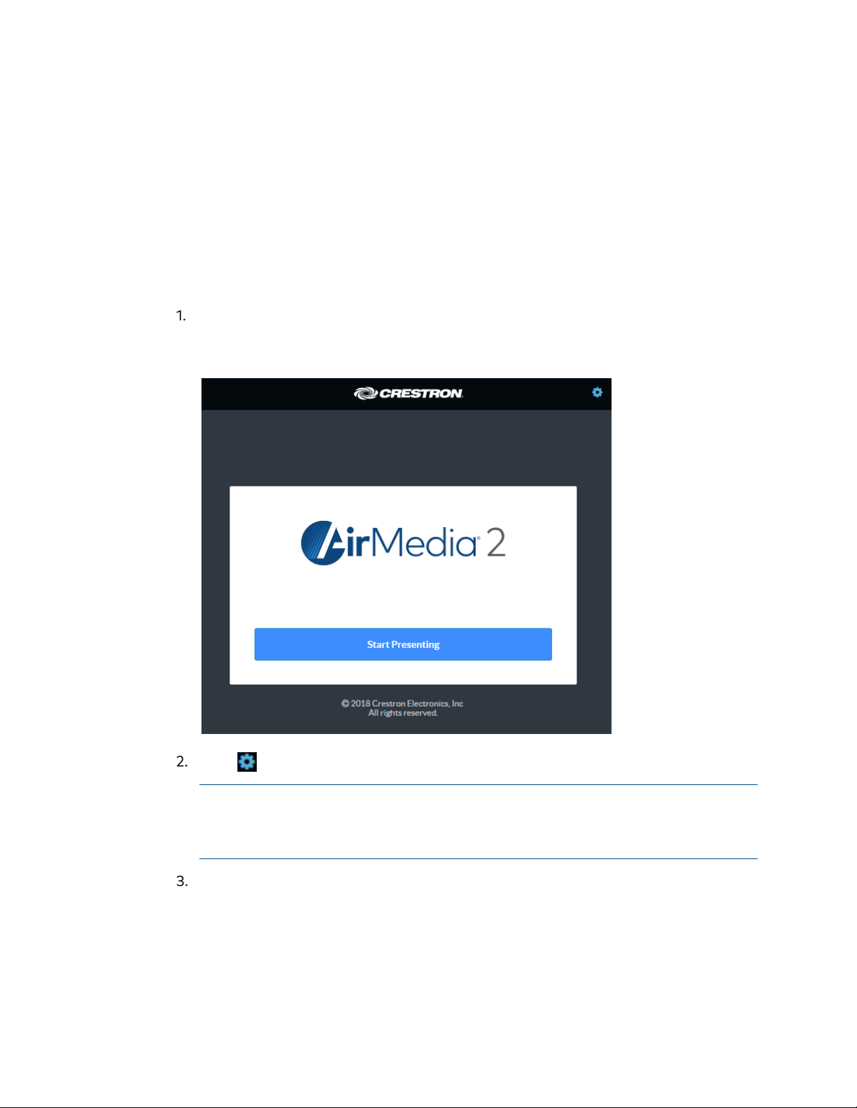
On the computer, open a web browser and navigate to the IP address or host
name that is shown on the display device. The welcome screen is displayed.
Welcome Screen
Click to continue. A prompt for the user name and password is displayed.
NOTE: Prior to displaying the prompt for login credentials, the web browser may
display a security warning message about the security certificate. It is safe to
ignore this warning as long as the user verifies that the browser’s address bar
indicates the correct IP address or host name of the device.
Enter the default user name (“admin”) and password (“admin”), and press Enter
to continue. The device’s
Product Manual – DOC. 8254F AM-200/AM-300: AirMedia Presentation Systems • 5
Status screen is displayed.
Page 10
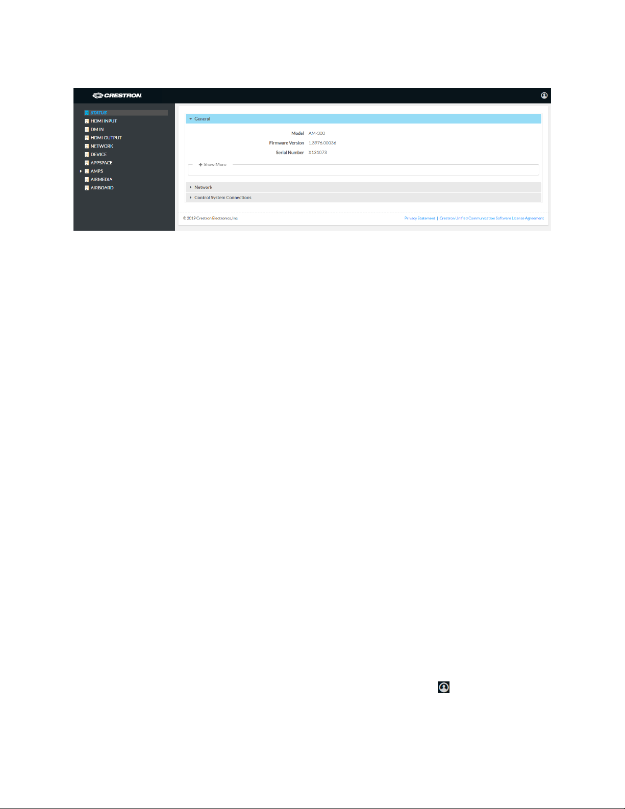
Status Screen
The Status screen displays information about the device and allows configuration of the
device’s operating parameters:
• STATUS contains general information about the device and network information.
- Click General to view general information.
- Click Network to view network information.
- Click Control System Connections to view information about the device’s
connection to a control system.
• HDMI INPUT configures the HDMI input.
• DM IN configures the DM® input (AM-300 only).
• HDMI OUTPUT displays information about the HDMI output.
• NETWORK configures the device for operation in a network environment.
• DEVICE is used to set the connected display’s standby time, upload firmware and
projects, reboot the device, view the system log, configure the control system
connection, and configure authentication management.
• APPSPACE is used to configure the device to work with the Appspace content
management application for digital signage.
• AMPS configures the settings for Crestron Fusion integration, meeting
functionality, room scheduling, and Zūm devices.
• AIRMEDIA configures the device’s AirMedia presentation gateway functionality.
• AIRBOARD configures the device’s functionality with a Crestron Airboard™.
When displayed on any screen, click + Show More to view more details or click - Show
Less to view fewer details.
Log Out from the Device
To log out from the device and return to the welcome screen, click .
6 • AM-200/AM-300: AirMedia Presentation Systems Product Manual – DOC. 8254F
Page 11
Configure the Device
Configure the device as required for the installation.
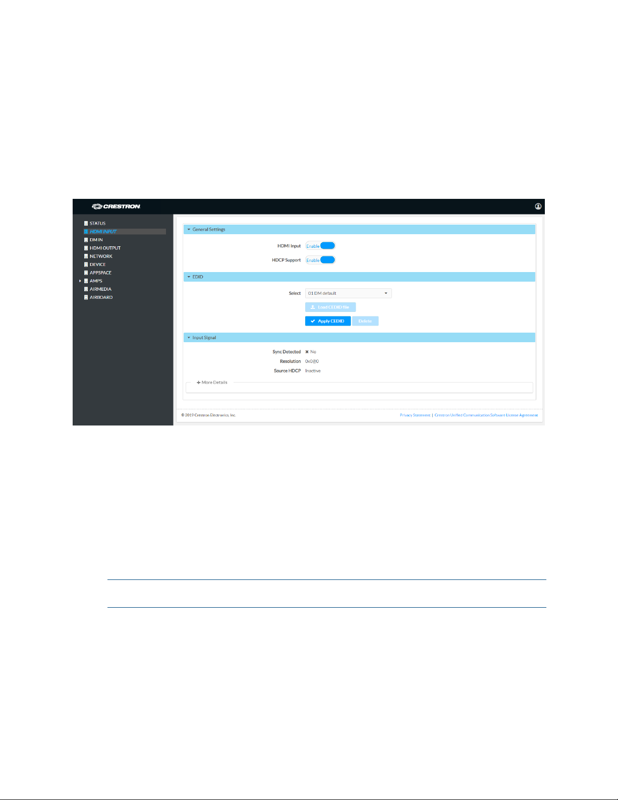
HDMI INPUT
Click HDMI INPUT to configure the HDMI input. The screen displays selectors for HDCP
support and EDID, as well as information about the input signal (if present).
HDMI INPUT Screen
General Settings
Select whether the HDMI Input should be set to Enable or Disable. When set to Enable,
sources connected to the HDMI input are received. When set to
connected to the HDMI input are not received.
Select whether HDCP Support should be set to Enable or Disable. When HDCP support
is enabled, source signals that require HDCP compliance are allowed to pass through to
the display that is connected to the HDMI output. When HDCP support is disabled,
source signals that require HDCP compliance are not allowed to pass through to the
connected display.
NOTE: When HDCP Support is set to Enable, the connected display must be HDCP
compliant as well.
Disable, sources
Product Manual – DOC. 8254F AM-200/AM-300: AirMedia Presentation Systems • 7
Page 12
EDID
EDID is a data structure provided by a digital display to describe its capabilities to a
video source (i.e., graphics card or set-top box). It is what enables a modern personal
computer to know what kinds of monitors are connected to it.
The EDID section of the HDMI INPUT screen specifies the EDID profile that is selected
for use. Only source devices that use the selected EDID profile are allowed to send
signals through the device.
To select an EDID profile to support, select one of the profiles to support from the dropdown list, and click
If a profile is not listed in the menu, a custom profile can be loaded onto the device. To
load a custom CEDID profile, follow this procedure:
From the Select drop-down list, select Custom.
Click Load CEDID file.
Click Browse and navigate to the location of the custom CEDID file.
Apply CEDID.
Select the file to use and click Open.
Click Send EDID.
Input Signal
Click Input Signal to view details about the input signal connected to the HDMI input
port.
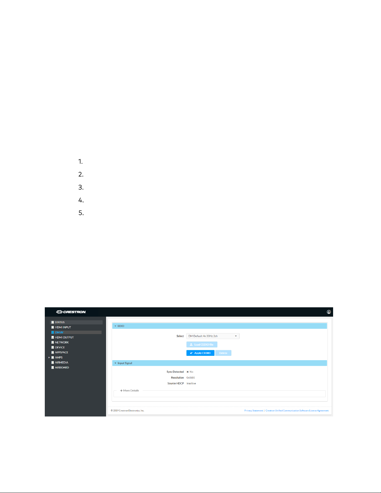
DM IN (AM-300 Only)
Click DM IN to configure the DM input. The screen displays a selector for EDID, as well as
information about the input signal (if present).
DM IN Screen
8 • AM-200/AM-300: AirMedia Presentation Systems Product Manual – DOC. 8254F
Page 13
EDID
EDID is a data structure provided by a digital display to describe its capabilities to a
video source (i.e., graphics card or set-top box). It is what enables a modern personal
computer to know what kinds of monitors are connected to it.
The EDID section of the DM INPUT screen specifies the EDID profile that is selected for
use. Only source devices that use the selected EDID profile are allowed to send signals
through the device.
To select an EDID profile to support, select one of the profiles to support from the dropdown list, and click
If a profile is not listed in the menu, a custom profile can be loaded onto the device. To
load a custom CEDID profile, follow this procedure:
From the Select drop-down list, select Custom.
Click Load CEDID file.
Click Browse and navigate to the location of the custom CEDID file.
Apply CEDID.
Select the file to use and click Open.
Click Send EDID.
Input Signal
Click Input Signal to view details about the input signal connected to the DM input port.
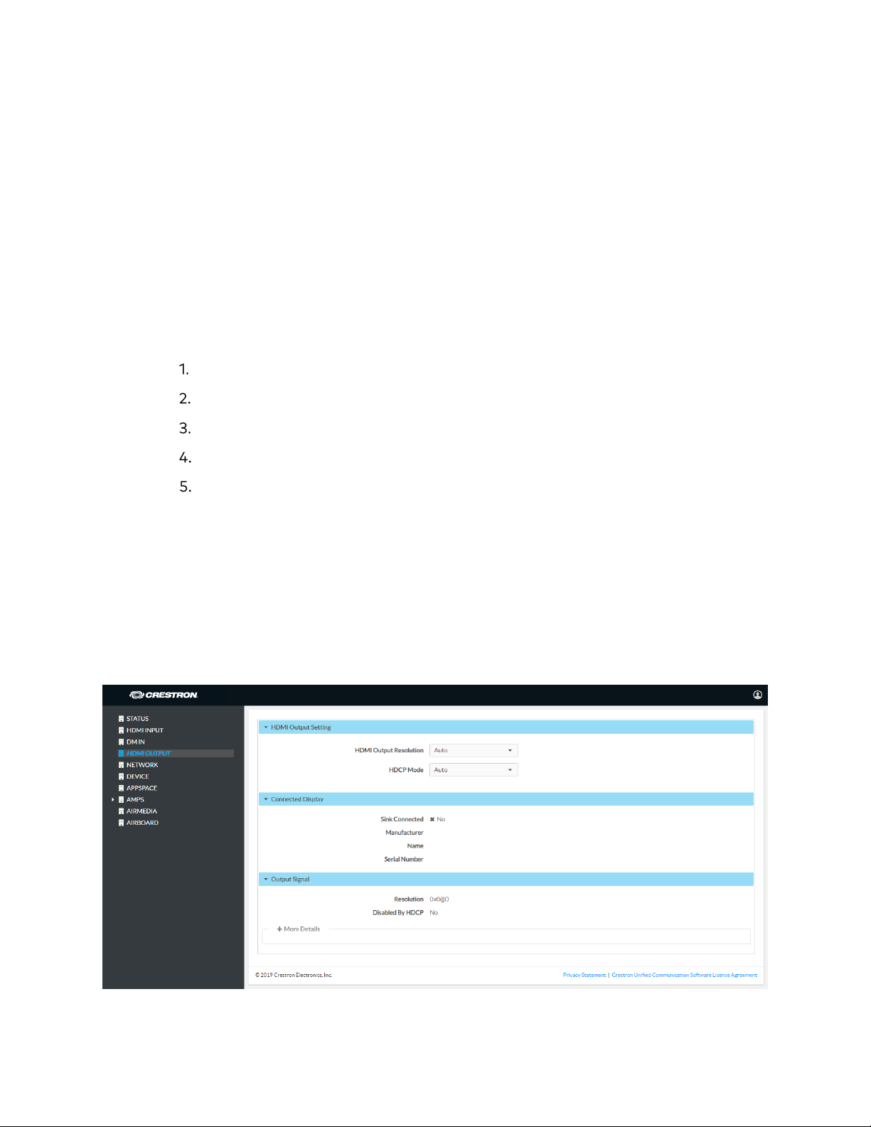
HDMI OUTPUT
Click HDMI OUTPUT to change settings for the HDMI OUTPUT port and to display
information about the connected display and output signal.
HDMI OUTPUT Screen
Product Manual – DOC. 8254F AM-200/AM-300: AirMedia Presentation Systems • 9
Page 14

HDMI Output Setting
• Select the output resolution from the HDMI Output Resolution drop-down list.
• Select the HDCP mode from the HDCP Mode drop-down list.
When
compliance on the output device if support is detected on the display device.
When
attempt to use HDCP compliance on the output even if downstream devices do
not support HDCP.
When
compliance with downstream devices, regardless of support.
HDCP Mode is set to Auto, the device will always attempt to use HDCP
HDCP Mode is set to Always (AM-300 only), the device will always
HDCP Mode is set to Never, the device will never attempt to use HDCP
Connected Display
Click Connected Display to view details about the device connected to the HDMI output
port.
Output Signal
Click Output Signal to view details about the signal sent to the HDMI output port.
NETWORK
Click NETWORK to configure the device for operating in a network environment. The
screen displays controls for configuring the network settings and 802.1x authentication.
10 • AM-200/AM-300: AirMedia Presentation Systems Product Manual – DOC. 8254F
Page 15
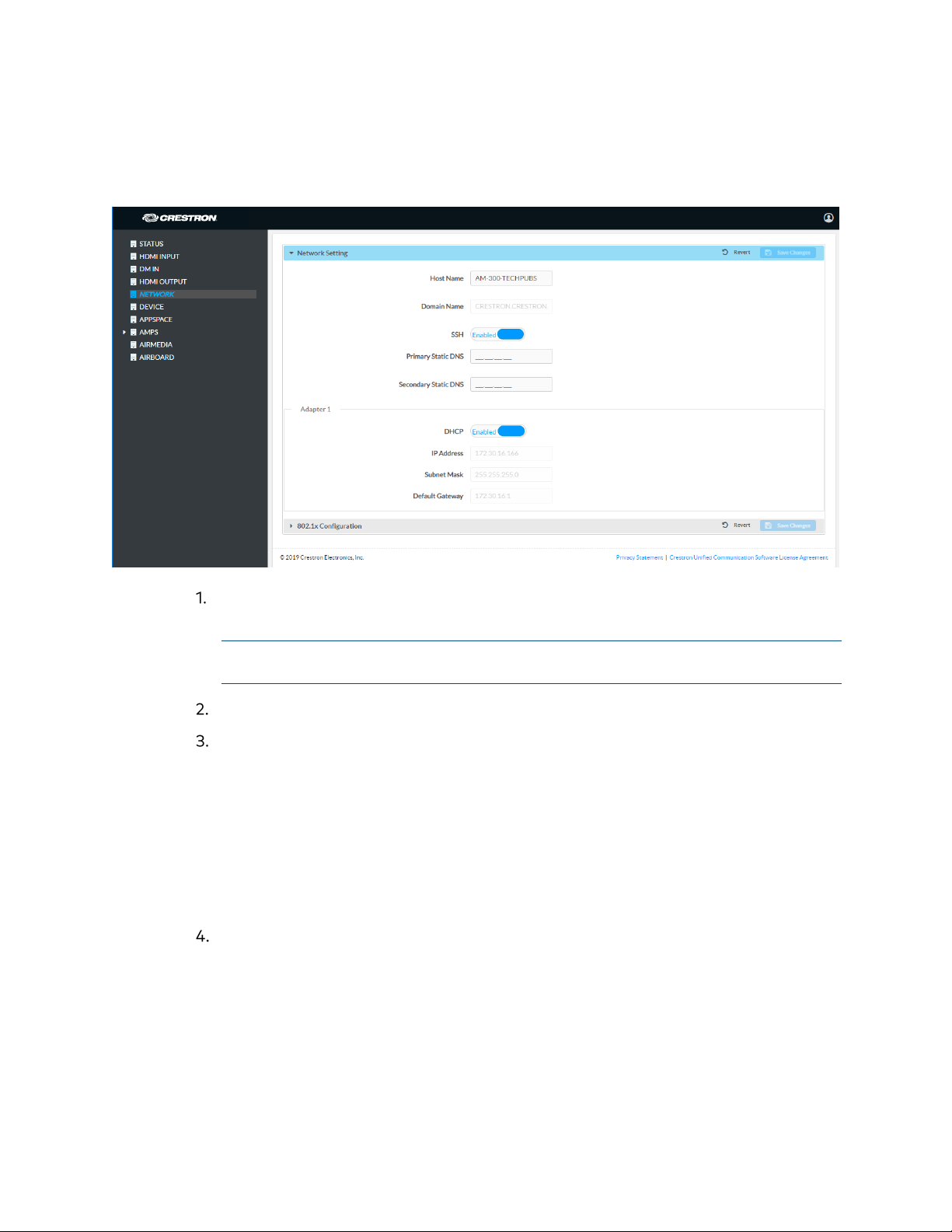
Network Setting
To configure the network settings, follow this procedure:
NETWORK Screen - Network Setting
Enter a host name (15 characters or less) in the Host Name field and a domain
name (optional) in the
Domain Name field.
NOTE: Use a host name and domain name as an alternative to IP addressing
when connecting client computers to the device.
Select whether Secure Shell protocol (SSH) should be Enabled or Disabled.
The network adapter can be set to have the DHCP server automatically provide
the IP address, subnet mask, default gateway, and DNS settings or to enable
entering these settings manually. Choose one of the following options.
- Set DHCP to Enabled to use a DHCP server to automatically provide the IP
address, subnet mask, default gateway, and DNS server.
- Set DHCP to Disabled to manually enter the Ethernet parameters. When set
to
Off, the IP address, subnet mask, default gateway, and DNS servers must
be manually entered.
Click Save Changes to apply any changes. Click Revert to revert back to the
previously used settings.
802.1x Configuration
Some networks require devices to use 802.1x port-based network access control for
access to the network.
Product Manual – DOC. 8254F AM-200/AM-300: AirMedia Presentation Systems • 11
Page 16
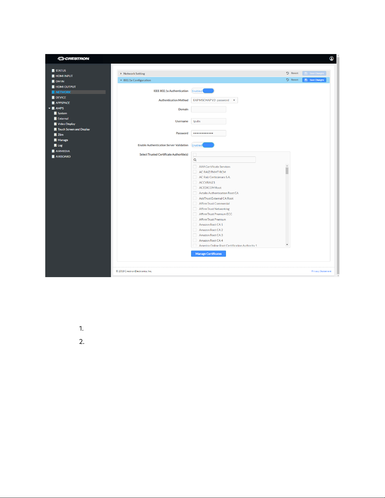
NETWORK Screen - 802.1x Configuration
To use 802.1x, set IEEE 802.1x Authentication to Enabled and select the desired method
of authentication.
Certificate Authentication
In the Authentication Method field, select EAP-TLS Certificate.
Enter the domain name of the authentication server.
12 • AM-200/AM-300: AirMedia Presentation Systems Product Manual – DOC. 8254F
Page 17
Upload a machine certificate.
a. Click Manage Certificates to manage certificates for 802.1x authentication.
A list of certificates is displayed.
Manage Certificates Dialog Box
b. Click the Machine tab. The current machine certificate is displayed.
c. Click to delete the certificate from the list of certificates.
d. Click Add Machine Certificate. The Add Certificate dialog box is displayed.
Add Certificate Dialog Box
e. Click Browse, select the certificate file, and click Open.
f. When prompted, enter the password used to encrypt the file.
g. Click Load to upload the certificate to the device. A message confirming the
upload is displayed.
h. Click OK to close the Add Certificate dialog box.
Product Manual – DOC. 8254F AM-200/AM-300: AirMedia Presentation Systems • 13
Page 18
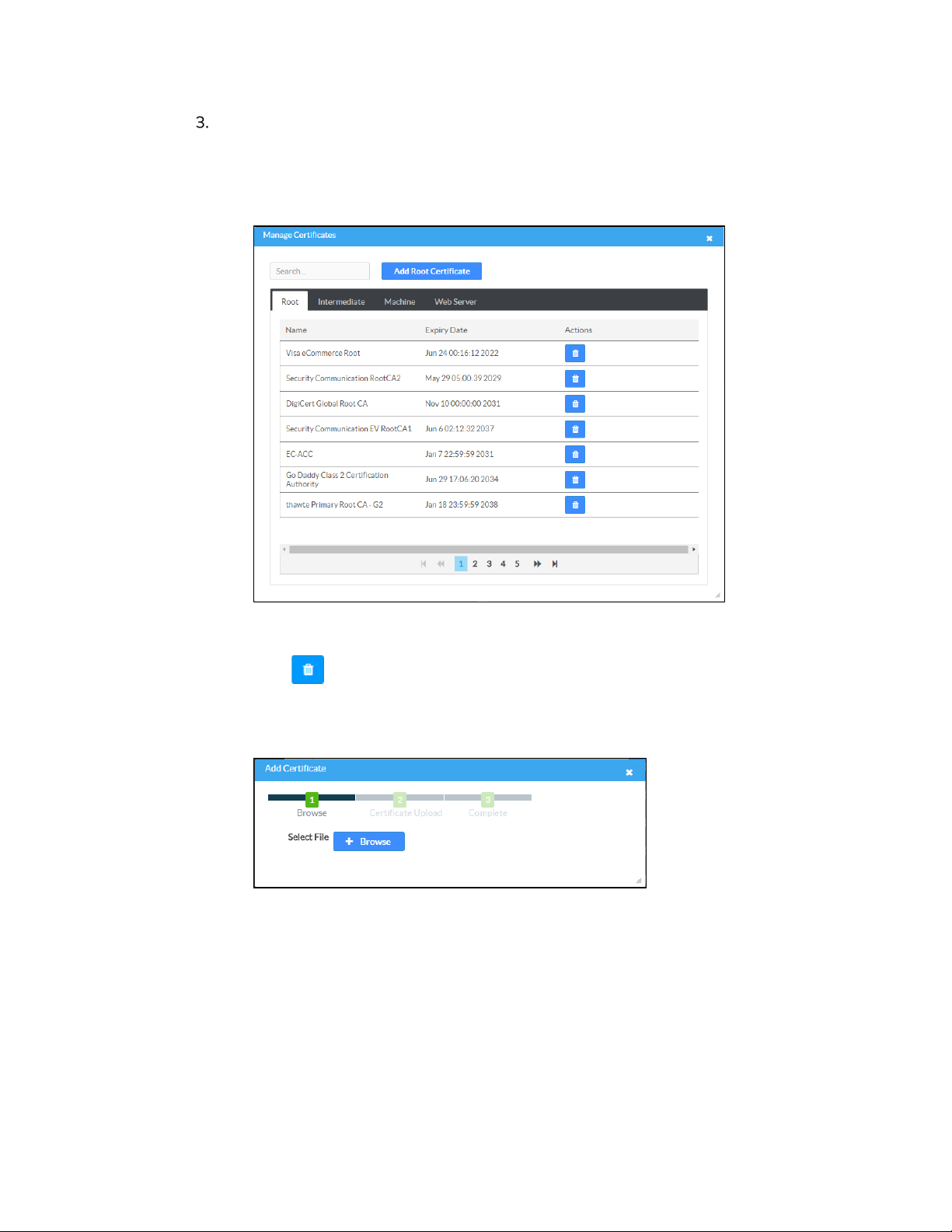
If authentication server validation is not used, set Enable Server Validation to
Disabled and continue to step 6. Otherwise, set Enable Server Validation to
Enabled and select the trusted certificate authorities to use.
- To select all of the authorities, click the check box next to the search box. To
unselect all of the authorities, click the check box again.
- To search for a specific authority, start typing the name of the authority in
the search box and check the box next to the desired authority.
Click Manage Certificates to manage certificates for 802.1x authentication. A
list of certificates is displayed.
Manage Certificates Dialog Box
a. Click to delete a certificate from the list of certificates.
b. Click Add Root Certificate. The Add Certificate dialog box is displayed.
Add Certificate Dialog Box
c. Click Browse, select the certificate file, and click Open.
d. Click Load to upload the certificate to the device. A message confirming the
upload is displayed.
14 • AM-200/AM-300: AirMedia Presentation Systems Product Manual – DOC. 8254F
Page 19
e. Click OK to close the Add Certificate dialog box.
Click Save Changes when done or Revert to return to the previous setting.
Password Authentication
In the Authentication Method field, select EAP-MSCHAP V2-password.
Enter the domain name of the authentication server, the user name, and the
password in their respective fields.
Set Enable Server Validation to Enabled and select the trusted certificate
authorities to use.
- To select all of the authorities, click the check box next to the search box. To
unselect all of the authorities, click the check box again.
- To search for a specific authority, start typing the name of the authority in
the search box and check the boxes next to the desired authorities.
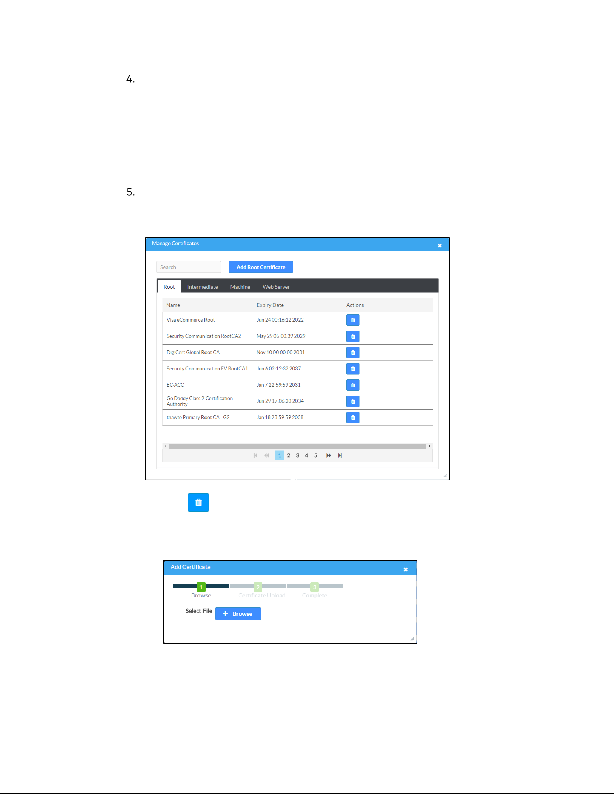
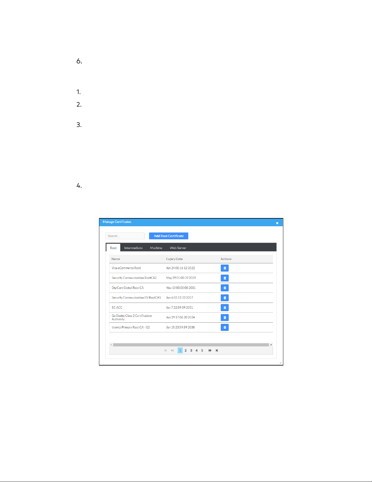
To load a custom certificate, click Manage Certificates and follow this procedure:
a. Click the Root tab to manage certificates for 802.1x authentication.
Manage Certificates: Root Tab
Product Manual – DOC. 8254F AM-200/AM-300: AirMedia Presentation Systems • 15
Page 20
b. Click Add Root Certificate. The Add Certificate dialog box is displayed.
Add Certificate Dialog Box
c. Click Browse, select the certificate file, and click Open.
d. Click Load to upload the certificate to the device. A message confirming the
upload is displayed.
e. Click OK to close the Add Certificate dialog box.
Click Save Changes when done or Revert to return to the previous setting.
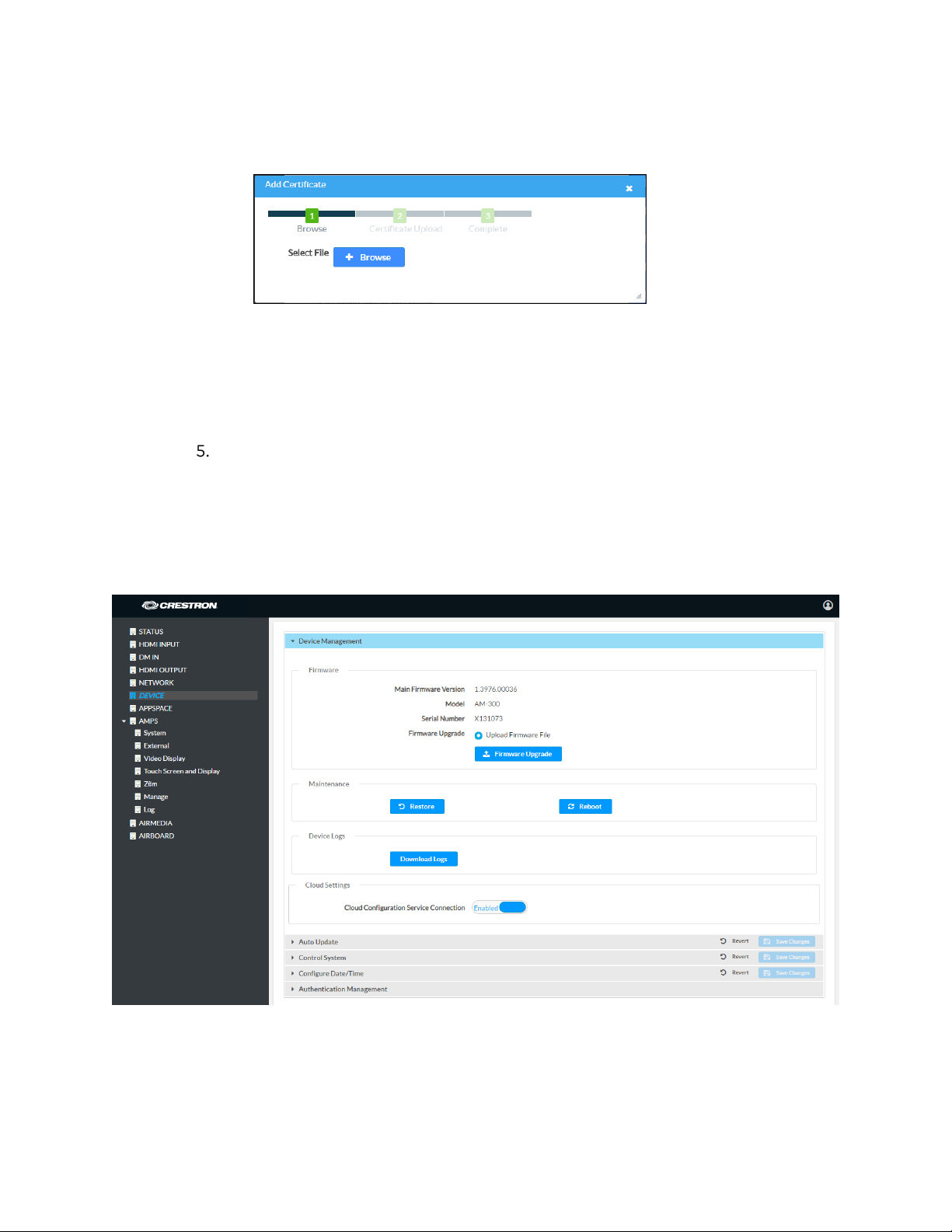
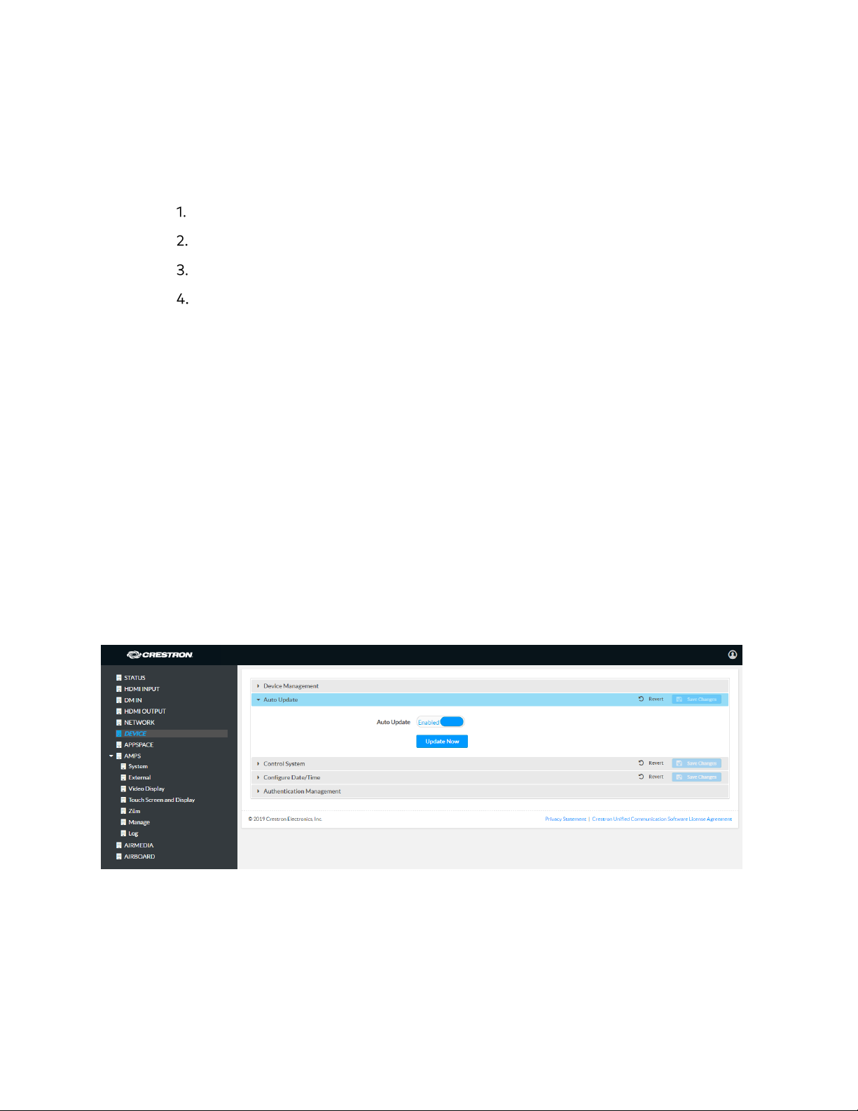
DEVICE
Click DEVICE to manage the device, enable automatic updates, identify the device to a
control system, configure date and time, and configure authentication management.
DEVICE Screen –Device Management
16 • AM-200/AM-300: AirMedia Presentation Systems Product Manual – DOC. 8254F
Page 21
Device Management
Firmware
To upload device firmware, follow this procedure:
Click Firmware Upgrade.
Click Browse and navigate to the location of the firmware file.
Select the file to use and click Open.
Click Load to load the firmware.
Maintenance
Click Restore to restore the factory settings. Click Reboot to reboot the device.
Device Logs
Click Download Logs to download the device’s system logs to the PC.
Cloud Settings
The Cloud Settings section controls the device’s connection to the Crestron XiO Cloud
service. By default, the
disable the connection, set
more information, refer to “
Auto Update
DEVICE Screen - Auto Update
Cloud Configuration Service Connection is set to Enabled. To
Cloud Configuration Service Connection to Disabled. For
Crestron XiO Cloud Service” on page 45.
The device can automatically check for firmware updates and update the device as
needed.
To allow auto updating, set Auto Update to Enabled. To turn off auto updating, set
Auto Update to Disabled.
To check for available updates, click Update Now.
Product Manual – DOC. 8254F AM-200/AM-300: AirMedia Presentation Systems • 17
Page 22
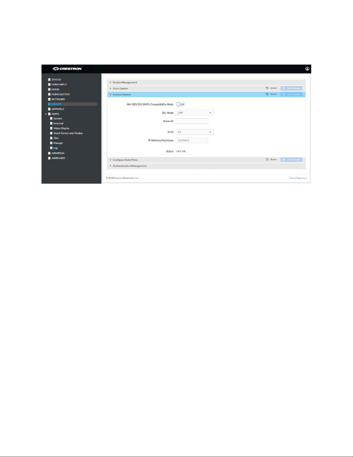
Control System
DEVICE Screen - Control System (AM-200 Shown)
The device can be controlled by a Crestron control system or virtual control system’s
SIMPL or SIMPL# program.
AM-100/AM-101 Compatibility
An AM-200 can be used as a direct replacement for an AM-100 or AM-101 AirMedia
Presentation Gateway in a SIMPL Windows program without any reprogramming. To
use the AM-200 as a replacement for an AM-100 or AM-101, set
AM-100/101 SIMPL
Compatibility Mode to On. Otherwise set the switch to Off.
SSL Mode
The device can use SSL encryption for communication with the control system. SSL can
be used with or without a CA certificate.
Select an SSL mode from the SSL Mode drop-down list.
• OFF: SSL is not used for communication between the device and the control
system
• Encrypt: SSL is used for communication between the device and the control
system. User-level authentication is optional. If using authentication, enter the
following information:
- Control System Username: The login name for the control system.
- Control System Password: The password used to log in to the control
system.
- Confirm Password: Confirm the password used to log in to the control
system.
18 • AM-200/AM-300: AirMedia Presentation Systems Product Manual – DOC. 8254F
Page 23

• Encrypt and Validate: SSL is used for communication between the device and
the control system. The control system will be validated against a root CA
certificate. User-level authentication is optional. If using authentication, enter the
following information:
- Control System Username: The login name for the control system.
- Control System Password: The password used to log in to the control
system.
- Confirm Password: Confirm the password used to log in to the control
system.
If using the Encrypt and Validate setting, a root certificate must be placed in the
/SYS directory on the device. Use FTP software to place the root certificate in
the /SYS directory on the device.
NOTE: The root certificate file name must have a
rootCA_cert.pem
.
.PEM
extension. i.e.
Control System Connection
To specify the control system connection:
Enter a descriptive name for the device in the Room ID field.
Select the IP ID of the device from the IP ID drop-down list.
NOTE: The IP ID must match the IP ID defined in the SIMPL Windows or SIMPL#
program.
Enter the control system’s IP address or host name in the IP Address/Hostname
field.
Click Save Changes to apply any changes. Click Revert to revert back to the
previously used settings.
The Status field indicates a connection to the control system program if the device is
listed in the control system’s IP table.
Product Manual – DOC. 8254F AM-200/AM-300: AirMedia Presentation Systems • 19
Page 24

Configure the Date and Time
DEVICE Screen - Configure Date/Time
The device’s internal clock can be synchronized with a time server or set manually.
NOTE: The time is automatically set when connected to Crestron Fusion. Any settings
made here do not apply.
Use Time Server Synchronization
1. Set Enable Time Synchronization to On.
2. Enter the time server’s IP address or host name in the Time Server field.
3. Click Synchronize Now to sync the device with the specified time server.
Set the Time Manually
Set Enable Time Synchronization to Off.
Select the time zone from the Time Zones list.
Enter the time (in 24 hour format) in the Time(24hr Format) field.
Click on the Date field, and then click to select a date from the calendar that is
displayed.
Click Save Changes to apply any changes. Click Revert to revert back to the
previously used settings.
20 • AM-200/AM-300: AirMedia Presentation Systems Product Manual – DOC. 8254F
Page 25

Details Edit Delete
Authentication Management
DEVICE Screen - Authentication Management
This section is used to set the password for the current user, and to manage authorized
users and user groups. By default,
Enable Authentication is set to On.
Current User
Click the Current User tab to view information about the current user and change the
password.
Click Change Current User Password to change the current user’s password.
Enter the new password in the Password field.
Confirm the new password in the Confirm Password field.
Click OK to set the new password or click Cancel to cancel.
Users
Click the Users tab to manage and create authorized users. A list of authorized users is
displayed.
DEVICE Screen - Authentication Management: Users Tab
Product Manual – DOC. 8254F AM-200/AM-300: AirMedia Presentation Systems • 21
Page 26

Search for a User
To search for a user, enter the name in the Search Users box, and press Enter.
View User Details
To view details about a user, click . Click OK when done.
Update a User
To update a user’s information, click .
Update User Dialog Box
Enter the user password in the Password field.
Confirm the password in the Confirm Password field.
Select the user’s group memberships from the Groups drop-down list.
Select whether the user is a member of the Active Directory® group with the
Active Directory User switch.
Click OK to save the changes or click Cancel to cancel.
Delete a User
To delete a user from the list of authorized users, click . Click Yes to confirm or No to
cancel.
22 • AM-200/AM-300: AirMedia Presentation Systems Product Manual – DOC. 8254F
Page 27

Details Delete
Create a User
To create a user:
Click Create User. The Create User dialog box is displayed.
Create User Dialog Box
Enter the user name in the Name field.
Enter the user password in the Password field.
Confirm the password in the Confirm Password field.
Select the user’s group memberships from the Groups drop-down list.
Select whether the user is a member of the Active Directory group with the
Active Directory User switch.
Click OK to save the user or click Cancel to cancel.
User Groups
Click the Groups tab to configure user groups. A list of user groups is displayed.
DEVICE Screen - Authentication Management: Groups Tab
Product Manual – DOC. 8254F AM-200/AM-300: AirMedia Presentation Systems • 23
Page 28

Search for a Group
To search for a group, enter the name in the Search Groups box, and press Enter.
View Group Details
To view details about a group, click . Click OK when done.
Delete a Group
To delete a group from the list of groups, click . Click Yes to confirm or No to cancel.
Create a User Group
To create a user group:
Click Create Group. The Create Group dialog box is displayed.
Create Group Dialog Box
Enter the group name in the Name field.
Select the group’s access level from the Access Level drop-down list.
- Administrator grants full access to the system settings and device functions.
- Connect grants access to the device functions.
- Operator grants read access to the system settings and full access to the
device functions.
- Programmer grants access to program/project specific settings/ReadOnly to
the rest, read/write access to the file system, no access to the setup project.
- User grants access to the device functions.
Set the Active Directory Group setting to Off or On.
Click OK to save the group or click Cancel to cancel.
24 • AM-200/AM-300: AirMedia Presentation Systems Product Manual – DOC. 8254F
Page 29

APPSPACE
The AM-200 and AM-300 can display content from an Appspace digital signage channel
onscreen when a presentation source is not active or the room is not occupied.
NOTES:
• An active Appspace account is required.
• Appspace video service is not supported.
• To use Appspace when the device is in Standby, the Power Settings must be set
to “
28
Click APPSPACE to configure the device’s operation with the Appspace platform.
APPSPACE Screen
Occupancy Based With Signage” as described in “Power Settings” on page
.
To configure the device for use with Appspace:
1. Set Appspace Integration to Enabled to enable Appspace when the device goes
to sleep based on occupancy (Standby). When enabled, the connected display will
show Appspace content.
NOTE: To use Appspace when the device is in Standby, the Power Settings must
be set to “Occupancy Based With Signage” as described in “Power Settings” on
page 28
.
2. Choose the Account Location.
− Public Cloud: Select this option to use the Appspace public web app.
− Private Instance: Select this option to use a privately hosted instance of the
Appspace web app.
3. Enter the Appspace App URL. This is the URL where a privately hosted instance
of the Appspace web app can be found. Leave blank if the
Public Cloud account
location is selected.
Product Manual – DOC. 8254F AM-200/AM-300: AirMedia Presentation Systems • 25
Page 30

4. Set Signage in Standby to Enabled to display Appspace content when the
CCS-UC-1 goes to sleep based on occupancy. Set to
feature.
5. Set Signage as a Background to Enabled to display Appspace content on the
connected display behind the calendar, date/time, system name, connection info
and branding portions of the display.
NOTE: When set to Enabled, the Enable Custom Backgrounds and Interval
Between Backgrounds options on the Room Schedule screen (described in
“Display Customization” on page 35) are disabled.
6. Click Save Changes when done or Revert to return to the previous setting.
NOTE: For best practices on configuring the AM-200/300 for use with Appspace
please visit https://docs.appspace.com/appspace/7.0/deviceadministration/basic/configure-device-integrations/crestron-mercury/
Disabled to turn off the
26 • AM-200/AM-300: AirMedia Presentation Systems Product Manual – DOC. 8254F
Page 31

AMPS
Click AMPS to configure the device’s .AV Framework™ platform functionality. This menu
contains options for configuring system settings, controlling Crestron Fusion software
operation, configuring the connected video display, configuring front panel operation,
adding and monitoring Zūm devices, managing the system’s configuration, and viewing
activity logs.
System
The System screen specifies the room name, the local language setting, the time format,
the date format, and manages the power settings.
AMPS Screen - System
Product Manual – DOC. 8254F AM-200/AM-300: AirMedia Presentation Systems • 27
Page 32

System Settings
To configure the system settings, follow this procedure:
Click System to display the AVF (System) screen.
In the Room Name field, enter the name of the room where the device is
installed.
Select the local language from the Language drop-down list.
Select the time format from the Time Format drop-down list (12 hour or 24
hour).
Select the date format from the Date Format drop-down list.
Power Settings
Configure power settings to manage the system’s power usage. To configure the power
settings, follow this procedure:
Select one of the following modes from the Standby drop-down list.
- Always On sets the following:
NOTE: Always On is the default setting.
The connected display will be on during business hours (defined in step 2).
The touch screen will always be on.
Crestron Fusion power events will be ignored.
During business hours, “Occupancy Vacant” events will be ignored.
During business hours “Occupancy Occupied” events will turn the room on
if the room is off.
Outside of business hours, Occupancy events can turn the room on and
off.
Hard button power events will be allowed.
HDMI sync and video route will turn the room on outside of business
hours.
Panel hard button will be active to turn off the connected display and the
touch screen will be blank.
- Based on Occupancy sets the following:
The connected occupancy sensor will be used to determine when the room
is occupied or vacant.
When the room is occupied the system will be on.
When the room is vacant the system will be off.
28 • AM-200/AM-300: AirMedia Presentation Systems Product Manual – DOC. 8254F
Page 33

If the connected display is configured as a controlled display, it will be on
when the room is occupied and off when the room is vacant.
The touch screen will be on when the room is occupied and off when the
room is vacant.
Crestron Fusion power events will not be ignored.
A detected video sync signal will turn on the room.
Connecting to the device by an AirMedia connection will not turn on the
room.
- Occupancy Based With Signage sets the following:
The occupancy sensor will be used to determine when the room is
occupied or vacant.
When the room is occupied the system will be on.
When the room is vacant, the system will be operating in standby mode
during defined business hours and off outside of business hours (defined
in step 2).
The connected display will be on when the system is in standby mode and
off when the system is off.
The touch screen will be on when the room is occupied and off when the
room is vacant.
When in the standby mode, digital signage that is configured to run
during standby mode will be displayed.
Crestron Fusion power events will not be ignored.
Connecting an active HDMI input source will turn on the room.
Connecting to the device by an AirMedia connection will not turn on the
room.
NOTE: The Occupancy Based With Signage setting must be selected if
Appspace is to be used.
For each day of the week, define business hours:
- Enabled sets whether the day is part of the business hours schedule. Set the
switch to
Set the switch to
Enabled to have the day included in the business hours schedule.
Disabled to remove the day from the business hours
schedule.
- Display on sets the time the connected display will turn on. To set the on
time, click the hour, then click the exact time.
- Display Off sets the time the connected display will turn off. To set the off
time, click the hour, then click the exact time.
Click Save to save the settings.
Product Manual – DOC. 8254F AM-200/AM-300: AirMedia Presentation Systems • 29
Page 34

Always On
Standby Off
Allow Crestron Fusion Power On
Allow Crestron Fusion Power Off
Allow Video Sync Power On
Allow Video Route Power On
Allow Hard Button Power Off
Allow Hard Button Power On
Allow Fixed Schedule Power Control
Allow Occupancy Power Control
*
Allow Display Back Light Control
Allow Display Touch Activity Power On
The following table shows which operations are enabled for each Standby setting.
Standby Settings and Enabled Operations
STANDBY SETTING
OPERATION
* After business hours.
ALWAYS
ON
OCCUPANCY
BASED
OCCUPANCY
BASED WITH
SIGNAGE
External
The External screen displays the settings for operating with Crestron Fusion.
AMPS Screen - External
Crestron Fusion Settings
To configure the Crestron Fusion settings, follow this procedure:
In the Crestron Fusion Room Name field, enter the name to be used by the
Crestron Fusion server.
30 • AM-200/AM-300: AirMedia Presentation Systems Product Manual – DOC. 8254F
Page 35

In the IPID field, enter the IP ID number to be used by the Crestron Fusion server.
To allow an AM-200 or AM-300 to appear in Crestron Fusion with only AirMedia
related settings, set
Report AirMedia Asset Only to Enable (optional). To enable
viewing of all settings related to the AM-200/300 and associated peripherals in
Crestron Fusion, set
Report AirMedia Asset Only to Disable.
In the Crestron Fusion Cloud URL field, click Enable to allow autodiscovery by
the Crestron Fusion server.
Click Save to save the settings or click Disable to disable the settings.
Upon completion, the device should be brought into Crestron Fusion software as a
processor. For details, refer to the Crestron Fusion help file.
Calendar Settings
To configure the calendar settings, follow this procedure:
Select the scheduling type from the drop-down list.
- Select SchedulingType Fusion to use Crestron Fusion for calendar functions.
- Select SchedulingType Exchange to use Microsoft Exchange Server®
software for calendar functions.
a. Enter the URL of the Exchange server in the Exchange EWS URL field.
b. Enter the domain name used by the Exchange server in the Domain field.
c. Enter the name of the conference room in the Username field.
d. Enter the password of the conference room in the Password field.
e. Enter the Calendar email address in the Calendar email address field.
NOTE: The Calendar email address is required only for accounts using
Impersonation.
f. (Optional) Check the Outlook Use Certificate box to use an Outlook®
certificate. Click
Upload and follow the instructions to upload a
certificate.
For more information, refer to Answer IDs 5829 and 5830 in the Online Help
on the Crestron website (www.crestron.com/onlinehelp
).
Click Save to save the settings or click Disable to disable the settings.
Product Manual – DOC. 8254F AM-200/AM-300: AirMedia Presentation Systems • 31
Page 36

Video Display
The Video Display screen configures the device for operation with the connected display.
Support for CEC, Crestron Connected®, IP, serial, and infrared profiles are built-in.
AMPS Screen - Video Display
To configure the device to work with a connected display, follow this procedure:
In the Display Name field, enter a name for the connected display.
In the Model drop-down list, select the display that is connected to the device.
NOTE: If a control system is used with the AM-200 or AM-300, select Non-
Controlled Display to use the AM-200 or AM-300’s IR and RS-232 ports and the
Control System to control the connected display.
Depending on the model selected, different controls are displayed. Complete the
required fields to use the selected display.
Click Save to save the settings.
32 • AM-200/AM-300: AirMedia Presentation Systems Product Manual – DOC. 8254F
Page 37

Touch Screen and Display
Click Touch Screen and Display to customize the function and appearance of the touch
screen and the connected display.
AMPS Screen – Touch Screen and Display
Product Manual – DOC. 8254F AM-200/AM-300: AirMedia Presentation Systems • 33
Page 38

General
The General section specifies what information is displayed on the touch screen and
connected display.
• Set Hide Meeting Subject to Disable to have the meeting’s subject shown. To
hide the meeting’s subject, set
Hide Meeting Subject to Enable.
• Select Hide Meeting Organizer to Disable to have the meeting’s organizer
shown.
To hide the meeting’s organizer, set Hide Meeting Organizer to Enable.
• Set Show Broadcast Message on Touch Screen to Enable to show broadcast
messages on the device’s touch screen (broadcast messages are automatically
displayed on the connected display). To prevent broadcast messages from
showing on the device’s touch screen, set
Show Broadcast Message on Touch
Screen to Disable.
• Enter the amount of minutes an emergency broadcast message is displayed in
the
Emergency Broadcast Timeout field.
NOTE: Emergency broadcasts are sent from Crestron Fusion. For more
information on emergency broadcasts, refer to the Crestron Fusion® Software
SSI Module Programming for SW-FUSION Reference Guide (Doc. 7898) at
www.crestron.com/manuals.
• Enter the amount of minutes a non-emergency broadcast message is displayed
in the
Non Emergency Broadcast Timeout field.
• Set Enable Touch Screen Auto Update to Enable to allow project files to be
pushed to the touch screen from the cloud automatically. To prevent the touch
screen’s project files from updating automatically, set
Enable Touch Screen Auto
Update to Disable.
When all changes are made, click Save to save the settings.
Touch Screen
Preloaded background images can be displayed on the device’s connected touch screen.
To select a background image for display:
Set Enable Custom Backgrounds to Enable. The Background drop-down list
displays.
Select an image from the Background drop-down list.
Click Save to set the image as the background image on the device’s connected
touch screen display.
NOTE: For details on adding a touch screen, refer to “Add a Touch Screen” on
page 67.
34 • AM-200/AM-300: AirMedia Presentation Systems Product Manual – DOC. 8254F
Page 39

Display Notifications
The Display Notifications section configures how notifications are displayed while the
device is in use.
• Enter the amount of time before the meeting’s remaining time is displayed in the
Time Remaining Message Starts field.
• Enter the amount of time the meeting’s time remaining message is displayed in
the
Time Remaining Message Duration field.
• Enter the amount of time before the next meeting’s information is displayed in
the
Next Meeting Information Shown field.
When all changes are made, click Save to save the settings.
Display Customization
The Display Customization section configures what is shown on the display device when
not in use.
• Set Hide Wired Cable Connection to Disable and enter information in Cable
Connection Details to display instructions for using cable connections. To hide
information on cable connections, set
Hide Wired Cable Connection to Enable.
• To show the clock and calendared events on the center of the display device, set
Show Calendar or Clock Overlay to Enable. To remove the clock and calendared
events from the center of the display device,
Show Calendar or Clock Overlay to
Disable.
• Set Show Background Overlay to Enable to place a monochrome filter over the
background images. Set
Show Background Overlay to Disable the filter and
show background images in full color.
• A custom logo can be displayed in the lower right corner of the display device
when the system is not in use. To use a logo or other graphic, set
Enable Custom
Logo Graphic to Enable, and enter the URL where the graphic is located in the
Custom Logo Graphic URL field. When set to Disable, the Crestron logo is
displayed.
NOTE: The optimal image size is 480 x 94 pixels. Custom graphics that are larger
than 480 x 94 pixels are scaled down while maintaining their aspect ratio.
Custom graphics that are smaller than 480 x 94 pixels are not scaled up and
should be resized for optimal image display.
Product Manual – DOC. 8254F AM-200/AM-300: AirMedia Presentation Systems • 35
Page 40

• A slideshow of custom backgrounds can be shown on the display device when the
system is not in use. To use custom backgrounds, set
Enable Custom
Backgrounds to Enable and enter the URL where the background images are
stored in the
that each background image is displayed, enter a time (in seconds) in the
Add Custom Background Url field. To specify the length of time
Interval
Between Backgrounds field.
NOTES:
• When Appspace is enabled, custom backgrounds cannot be used. For
information on using Appspace, refer to “APPSPACE” on page 25.
• The interface has been designed to use most of the screen area for
informational purposes. This feature is intended to for use with corporate
colors, branding, and aesthetics to the particular organization and should
not be used to add custom instructions for room users.
When all changes are made, click Save to save the settings.
A/V Routing
The A/V Routing section configures the order in which devices are routed. By default,
routing is automatic, meaning the source will immediately change once a new device is
engaged.
• Set AirMedia Auto-Route Only to Enable to have only the AM-200/AM-300
route automatically. Once enabled, any other sources (DM, HDMI, AirMedia and
AirBoard) must be manually routed via the touch screen. To route all sources
automatically when connected, set
AirMedia Auto-Route Only to Disable.
• While AirMedia Auto-Route Only is disabled, set Priority Routing to Enable to
dictate the order in which sources are routed using the chart.
To change the Display Name that appears on the touch panel, type a name
into the text field in the corresponding row of the device.
NOTE: Display Names may be changed regardless of AirMedia Auto-Route
Only setting.
To change the routing order of a device, select a number from the
corresponding dropdown box under the
Rank column. Devices with a lower
number rank will take priority over others.
Click Save to save any changes made to Display Names and Rank.
36 • AM-200/AM-300: AirMedia Presentation Systems Product Manual – DOC. 8254F
Page 41

Zūm
The AM-200 and AM-300 can use Zūm™ wireless occupancy sensors and keypads to
operate the presentation system. The
Zūm devices, and monitor Zūm devices.
AMPS Screen - Zūm
Zūm screen is used to create Zūm networks, add
Network
The Network section shows all the Zūm devices in the Zūm wireless network.
The Zūm Bridge field indicates the status of the ZUMMESH-AVBRIDGE Wireless Control
Integration Module.
The Zūm Sensor Status field indicates the status of the
ZUMMESH-PIR-OCCUPANCY-BATT Wireless Battery-Powered Occupancy Sensor.
Form a Network
The Form Network function is used whenever a new network needs to be created (i.e.,
after a ZUMMESH-AVBRIDGE is connected to the AM-200 or AM-300).
NOTES:
• Forming a network will erase any previously established network and remove and
joined devices.
• Zūm devices can be added and managed from ZUMMESH-AVBRIDGE and
supported Zūm devices. Refer to “
Add a Zūm Device to the Network” on page 66.
To form a new network:
Click Form Network. A new network is created with the ZUMMESH-AVBRIDGE
as the center of the network. The ZUMMESH-AVBRIDGE also enters the Joining
mode.
Product Manual – DOC. 8254F AM-200/AM-300: AirMedia Presentation Systems • 37
Page 42

Acquire Zūm devices to the ZUMMESH-AVBRIDGE. For details on specific Zūm
devices, refer to “
Add a Zūm Device to the Network” on page 66.
Click Stop Acquire after acquiring Zūm devices. The ZUMMESH-AVBRIDGE will
exit the Joining mode.
NOTE: The ZUMMESH-AVBRIDGE will automatically exit the Joining mode after
four minutes.
Add a Zūm Device
Supported Zūm devices can be added to an exisiting network. For a list of supported
devices, refer to “Supported Devices” on page 66.
To add a Zūm device:
Click Start Acquire. The ZUMMESH-AVBRIDGE enters the Joining mode.
Acquire Zūm devices to the ZUMMESH-AVBRIDGE. For details on specific Zūm
devices, refer to “
Add a Zūm Device to the Network” on page 66.
Click Stop Acquire after acquiring Zūm devices. The ZUMMESH-AVBRIDGE will
exit the Joining mode.
NOTE: The ZUMMESH-AVBRIDGE will automatically exit the Joining mode after
four minutes.
Manage
The Manage screen is used to enact the changes made in the web pages or revert to the
previous settings.
When changes are made to the AMPS settings, the device goes offline and the screen
below is shown.
AMPS Screen - Manage - System Offline
p
The connected display shows a message indicating that the system is currently offline.
38 • AM-200/AM-300: AirMedia Presentation Systems Product Manual – DOC. 8254F
Page 43

Additionally, if a touch screen is connected, it shows the following message.
Front Panel, System Configuration in Progress
Click Activate Configuration to carry out the changes that were made, or click Revert
Configuration to revert back to the previously saved settings. The screen below is shown.
AMPS Screen - Manage - System Online
Product Manual – DOC. 8254F AM-200/AM-300: AirMedia Presentation Systems • 39
Page 44

Log
The Log screen is used to view and download the device’s message logs for analysis.
AMPS Screen - Log
• Click the up or down arrows to scroll through the message log.
• Click Stop Scrolling to pause the message log. Click Scrolling to resume.
• Click Download to download the message log.
40 • AM-200/AM-300: AirMedia Presentation Systems Product Manual – DOC. 8254F
Page 45

AirMedia
Click AIRMEDIA to configure the device’s AirMedia functionality. The AIRMEDIA screen is
displayed.
NOTE: For additional details on deploying AirMedia, refer to the AirMedia Deployment
Guide (Doc 7693) at www.crestron.com/manuals.
AIRMEDIA Screen
Code
To enable AirMedia for wireless presentation, set AirMedia to Enabled. To turn off
AirMedia, set AirMedia to Disabled.
A code can be used to limit access to the device. The code feature can be disabled,
randomly generated, or fixed to a specific value. Select one of the following Login Code
Modes to specify how the access code is used:
• Disabled allows any user with the device’s IP address or host name to open a
client connection without entering an access code.
• Random sets the device to randomly generate an access code. A new code is
generated when the last connected presenter disconnects from the device. The
access code is displayed on the device’s screen when AirMedia is selected.
• Use the following code sets the device to display a user-specified, four-digit
access code. Enter a code in the
displayed on the device’s screen when AirMedia is selected.
To show the access code on the connected display when AirMedia is selected, set Display
Login Code to Enabled. To hide the login code, set Display Login Code to Disabled.
Login Code field and click Set. The access code is
Product Manual – DOC. 8254F AM-200/AM-300: AirMedia Presentation Systems • 41
Page 46

Connection Display Options
Select whether connection information is displayed on the connected display device as
well as what connection information is displayed.
• Set Show Connection Info to Enabled to display connection information on the
display device. Set
information.
• If Show Connection Info to Enabled, select the Connection Info Mode to
determine what connection information is presented to room visitors.
− Select IP Address to show the IP address to use for connecting to the system.
− Select Host to show the host name to use for connecting to the system.
− Select Host And Domain to show the host name and domain name to use for
connecting to the device.
− Select Custom to a custom string to use for connecting to the system. If a
custom string is to be used, enter it in the
Show Connection Info to Disabled to hide connection
Custom String field.
Crestron AirBoard
Click AIRBOARD to configure the device’s functionality with the Crestron AirBoard™
(CCS-WB-1). The
AIRBOARD Screen
Settings
To configure the settings, connect the Crestron AirBoard by following this procedure:
AIRBOARD screen is displayed.
To enable the Crestron AirBoard for use with the system, set Enable to Enabled.
To disable the Crestron AirBoard, set
Enable to Disabled.
Enter the Crestron AirBoard’s IP address or host name in the IP/Host field.
Click Save.
Connection Status is displayed below the IP/Host field.
42 • AM-200/AM-300: AirMedia Presentation Systems Product Manual – DOC. 8254F
Page 47

NOTE: After entering the IP address, it may take up to 1 minute for the connection
status to change from disconnected to connected.
Pairing the Device
Once the Crestron AirBoard is connected, it must be paired with the AM-200/AM-300.
To do this, complete the following steps:
Click Pair.
On the Crestron AirBoard’s control pad, press the blue button to pair the device.
Configuring the Device
Once the Crestron AirBoard is paired, it may be configured by completing the following
steps:
Select one of the following Code Modes to specify how the access code is used.
− Disabled allows any user with the device’s IP address or host name to open a
client connection without entering an access code.
− Random sets the device to randomly generate an access code. A new code is
generated when the last connected participant disconnects from the device.
The access code is displayed on the system’s screen.
Product Manual – DOC. 8254F AM-200/AM-300: AirMedia Presentation Systems • 43
Page 48

− Use the following code sets the device to display a user-specified, four-digit
access code. Enter a code in the
Login Code field.
Set Enable On Panel to Enable to allow Crestron AirBoard presentation on the
Present a Source screen of the touch panel. When enabled, will also appear in
the taskbar on the touch panel. Set
Enable On Panel to Disable to disallow
Crestron AirBoard presentation.
Set Show Connection Info to Enable to display connection information on the
PinPoint splash screen on the HDMI output when no source is active. Set
Show
Connection Info to Disable to stop displaying connection information.
To unpair the Crestron AirBoard and AM-200/AM-300, click Unpair.
Crestron Airboard Functional Recommendations and Notes:
• Crestron Airboard functionality requires a touch panel.
• A Crestron Airboard recording session must be initiated before it can be routed
to the display.
• If the AM-200/300 device is rebooted, the presentation routing to the display is
stopped. However, the active Crestron Airboard session is not.
• When unpairing a Crestron Airboard, it must be unpaired from the web user
interface before it can be paired again with another system.
• The Crestron AirBoard device does not distinguish between the organizer and
participants. Any allowed participant can accept or invite any other participant
into the session. Any participant who knows the login code can join an active
session and share a link with the login code to any other person
join the session without knowledge of the organizer
.
, allowing them to
44 • AM-200/AM-300: AirMedia Presentation Systems Product Manual – DOC. 8254F
Page 49

Enterprise Deployment Options
Crestron has two options for deploying multiple AM-200 and AM-300 devices across an
enterprise. These tools can assist in deploying any number of AM-200 or AM-300 devices
that an organization may need to deploy.
For more information, refer to Answer ID 5719 in the Online Help section of the Crestron
website (www.crestron.com/onlinehelp
Crestron XiO Cloud Service
The Crestron XiO Cloud service requires devices to be claimed so they can be managed
by the service. To claim a single device or multiple devices, perform one of the following
procedures.
Claim a Single Device
Record the MAC address and serial number that are labeled on the shipping box
or on a sticker attached to the device. The MAC address and serial number are
required to add the device to the Crestron XiO Cloud environment.
).
Open a web browser, and log in to the Crestron XiO Cloud service at
https://portal.crestron.io.
Click the ENVIRONMENT menu button ( ) to display the Environment menu.
Environment Menu
Click Claim Device. The Claim Device dialog box is displayed.
Claim Device Dialog Box
Product Manual – DOC. 8254F AM-200/AM-300: AirMedia Presentation Systems • 45
Page 50

MAC Address,Serial Number
00.10.7e.8b.87.c1,17284670
Enter the MAC address and serial number recorded in step 1 in the MAC Address
and Serial Number fields, respectively.
Click Claim. A message indicating a successful claiming displays.
NOTE: If an error message displays stating the device does not exist, connect the
device to a network that has access to the Internet, wait 15 minutes, and then try
again.
Click X to close the dialog box. The hostname of the claimed device appears in the
device tree under the group
The device can now be managed or assigned to a group. For information on creating
environments, managing devices, and managing users with the Crestron XiO Cloud
service, refer to the Crestron XiO Cloud Service User Guide Guide (Doc. 8214) at
www.crestron.com/manuals
Claim Multiple Devices
Record all of the MAC addresses and respective serial numbers in a comma
delimited, CSV file, and then save it to a location that is accessible to the
computer used to access the Crestron XiO Cloud service. The CSV file should be
formatted as shown in the following image:
Unassociated Devices.
.
CSV File Format
00.10.7e.8b.81.b6,17284712
00.10.7e.8b.8c.87,17284570
00.10.7e.96.83.93,1716JBG01207
00.10.7e.96.92.0a,1716JBG01550
NOTE: MAC addresses and serial numbers are labeled on the shipping box or on a
sticker attached to the device.
Open a web browser, and log in to the Crestron XiO Cloud service at
https://portal.crestron.io.
Click the ENVIRONMENT menu icon ( ) to display the Environment menu.
Environment Menu
Click Claim Multiple Devices from the drop-down menu. The Claim Multiple
Devices dialog box is displayed.
46 • AM-200/AM-300: AirMedia Presentation Systems Product Manual – DOC. 8254F
Page 51

Claim Multiple Devices Dialog Box
Click Choose and select the CSV file created in step 1.
Click Claim to claim all of the devices listed in the file. A message indicating the
claim status of each device is displayed.
NOTE: If an error message displays stating the device does not exist, connect the
device to a network that has access to the Internet, wait 15 minutes, and then try
again.
Click X to close the dialog box. The hostnames of the claimed devices appear in
the device tree under the group
The devices may now be managed or assigned to a group. For information on creating
environments, managing devices, and managing users with the Crestron XiO Cloud
service, refer to the Crestron XiO Cloud User Guide (Doc. 8214) at
www.crestron.com/manuals
.
Unassociated Devices.
Crestron Deployment Tool for PowerShell® Software
Crestron has developed a tool for customers without the ability to use CPS to assist in
deploying multiple devices without the need to configure each device individually. With
this tool, an administrator has the ability to input all of the settings to be configured on
multiple AM-200 and AM-300 devices, and then use PowerShell®
line shell and scripting language to configure the devices across a local network.
task-based command-
Product Manual – DOC. 8254F AM-200/AM-300: AirMedia Presentation Systems • 47
Page 52

Operation
On their own, the AM-200 and AM-300 can present content via the following
connections:
• A device connected to the HDMI INPUT port
• A device connected to the DM IN port (AM-300 only).
• AirMedia
• Crestron Airboard
By default, the AM-200 and AM-300 present the input that was last connected.
Optionally, a touch screen (sold separately or as part of a system) can be used to control
the system and manually determine which sources are displayed. Additionally, a keypad
(sold separately or as part of a system) can be used to adjust volume and turn the
system on or off. For instructions on using a touch screen, refer to “Touch Screen
Operation” below. For instructions on using a keypad, refer to “Keypad Operations” on
page 59. Otherwise, continue below.
Connect a Source
Connect a device to the HDMI INPUT port or any of the inputs on a connected DM
transmitter (AM-300 only). The last connected source is the device that is shown on the
display connected to the AM-200 or AM-300.
Touch Screen Operation
While the AM-200 and AM-300 always display the last connected source, a connected
touch screen can be used to switch the system power, switch between sources, and
adjust volume. The home screen is displayed upon system startup.
NOTE: Depending on the device’s configuration, some functions described here may not
be available.
Home Screen
48 • AM-200/AM-300: AirMedia Presentation Systems Product Manual – DOC. 8254F
Page 53

System Controls
The following controls are present on every screen.
System Power
Tap c to turn on system power. Tap again to turn off system power.
Home Screen
Tap m to return to the home screen.
Present
Tap to view presentation options. For details on presenting refer to “Present
Content” on page 52.
Volume Control
Tap or to raise or lower the volume.
NOTE: Volume controls are only present when the system is connected to a display that
supports volume control.
Schedule a Meeting
The Home screen is used to reserve the conference room.
Tap to display the Home screen. The Home screen displays the current status of the
room.
Home Screen - Reserved Room
Product Manual – DOC. 8254F AM-200/AM-300: AirMedia Presentation Systems • 49
Page 54

If the room is available for use, the display on the device indicates as such.
Home Screen - Available Room - Limited Time
Home Screen - Available Room - Remainder of Day
50 • AM-200/AM-300: AirMedia Presentation Systems Product Manual – DOC. 8254F
Page 55

The user can either use the room for the remaining time available or create a new
meeting for another time. To create a new meeting, follow this procedure:
Tap RESERVE NOW > to reserve the room. The New Meeting screen is displayed.
New Meeting Screen
The meeting start and end times are automatically populated for the next
available 30-minute block (
e.g
., 5:30 to 6:00, 5:45 to 6:15, 6:00 to 6:30,
etc.
).
When reserving a meeting space within a current 30-minute block, the start time
is rounded down to the nearest 5-minute increment. For example, tapping
RESERVE NOW at 5:44 pm creates a meeting with a start time of 5:40. If
RESERVE NOW is tapped at 5:46 pm, the meeting start time would be 5:45 pm.
The meeting end time may be set by the user.
NOTE: RESERVE NOW Meetings may only be scheduled for the current day from
the device.
Scroll through the available end times to select the duration of the meeting. The
room may be reserved for up to three lengths.
- Until the current half hour interval ends (If the current time is 5:44 pm, the
end time for this option is 6:00 pm.) This is the default setting.
- Until the current half hour interval ends plus 30 minutes (If the current time is
5:44 pm, the end time for this option is 6:30 pm.)
- Until the current half hour interval ends plus 60 minutes (If the current time is
5:44 pm, the end time for this option is 7:00 pm.)
NOTE: These options are available only if a meeting is not already scheduled
during that timeframe.
Tap RESERVE NOW to book the room.
Product Manual – DOC. 8254F AM-200/AM-300: AirMedia Presentation Systems • 51
Page 56

Present Content
Depending on the configuration, the system can present content from connected HDMI
and DigitalMedia sources as well as content streamed from wireless devices over
AirMedia. To view the different presentation options, tap . The
screen is displayed.
Present a Source Screen
Present a Source
Sources that have a signal present are indicated with . Sources that do not have a
signal present are indicated with .
NOTE: The AirBoard source will not be indicated in green unless the Crestron AirBoard
session has already been initiated. If you click the AirBoard button on the “Present a
Source” page and the session has not been initiated, it will automatically do so and route
the source to the display.
Present Via DM
Tap DM (AM-300 only) to display content from a device connected to a DM transmitter.
When done presenting, tap
Stop. To return to the previous screen, tap < Back.
52 • AM-200/AM-300: AirMedia Presentation Systems Product Manual – DOC. 8254F
Page 57

Now Presenting DM Screen
Present Via HDMI
Tap HDMI to display content from the device connected to the HDMI INPUT port. When
done presenting, tap
Stop. To return to the previous screen, tap < Back.
Now Presenting HDMI Screen
Product Manual – DOC. 8254F AM-200/AM-300: AirMedia Presentation Systems • 53
Page 58

Present Via Crestron Airboard
Tap AirBoard or in the taskbar at the bottom of the screen to display content from
a paired Crestron AirBoard device. The AirBoard® screen is displayed. When done
presenting, tap
AirBoard® Screen
Stop. To return to the previous screen, tap < Back.
NOTE: The session begins recording immediately upon starting a presentation. Tapping
Stop stops the presentation, but does not stop the recording session.
While presenting, three features are available from the AirBoard Screen: View
Participants, Stop Recording, and Send Snapshot.
View Participants
To see all participants currently viewing the presentation, tap View Participants. The
Participants screen is displayed. Tap to return to the AirBoard screen.
Participants Screen – In Session
54 • AM-200/AM-300: AirMedia Presentation Systems Product Manual – DOC. 8254F
Page 59

Participants can view the presentation by visiting airboard.crestron.com and
entering their name, the Crestron ID, and the code displayed on the AirBoard screen.
Once a participant has joined the session, their name will be displayed in the In
Session section of the Participants screen.
If Code Mode is disabled via the web interface, participants are not required to enter
a code into the “Enter Code” field. Instead of directly joining the session, they will be
placed into the lobby pending approval on the touch panel before being admitted.
Participants Screen – In Lobby
To admit a participant from the lobby into the session, press the beside their
name.
NOTE: The maximum number of remote participants is 10.
If a participant requests access while a presentation is not currently being recorded
and Code Mode is set to disabled, the following prompt will be displayed on the touch
panel:
Incoming Remote Connection Request Screen
Product Manual – DOC. 8254F AM-200/AM-300: AirMedia Presentation Systems • 55
Page 60

Tap Ignore to deny the request, or tap Accept to initiate a recording session and
admit the requesting participant into the new recording session.
Stop Recording
When done presenting, tap Stop Recording. The following screen is displayed.
To end the session without emailing a recording, tap Proceed without e-mailing. To send
an email recording of the session, tap
Email Recording. The following screen will be
displayed.
To send an email recording, perform the following steps:
1. Type an email address in the E-mail recording to: field. Multiple email addresses may
be entered separated by commas or semicolons.
2. Tap Send Snapshot to send an image of the Crestron AirBoard display, or tap Send
Slide Deck to send a slide deck (PDF) of all changes made to the whiteboard.
NOTE: The Send Slide Deck function requires the timeline be enabled and the
timeline length be set in the Crestron AirBoard web user interface.
56 • AM-200/AM-300: AirMedia Presentation Systems Product Manual – DOC. 8254F
Page 61

Send Snapshot
To send a snapshot of the presentation, tap Send Snapshot. The Send Snapshot
screen is displayed.
Send Snapshot Screen
Type an email address in the E-mail recording to: field. Then, tap Send Snapshot to
send an image of the whiteboard in its current state. Multiple email addresses may
be entered separated by commas or semicolons.
Meeting Conclusion Warning
When a scheduled meeting is almost over, the following prompt will appear.
Meeting Conclusion Warning
To end the recording and presenting session, select Stop recording & presenting. See
“
Stop Recording” on page 56 for information on sending recordings to participants
once the recording has been stopped. To continue recording and presenting past the
scheduled meeting length, select
Product Manual – DOC. 8254F AM-200/AM-300: AirMedia Presentation Systems • 57
Do not stop.
Page 62

Present Via AirMedia
Tap AirMedia to display content from a device connected through AirMedia. The
Connect to AirMedia® screen is displayed.
Connect to AirMedia® Screen
Refer to “Use AirMedia” on page 59 for instructions on connecting to AirMedia and
sharing content.
When sharing content over AirMedia, the following screen is displayed. When done
presenting, tap
Now Presenting AirMedia® Screen
Stop. To return to the previous screen, tap < Back.
58 • AM-200/AM-300: AirMedia Presentation Systems Product Manual – DOC. 8254F
Page 63

Keypad Operations
While the AM-200 and AM-300 always display the last connected source, a
ZUMMESH-KP10AMBATT AirMedia keypad can be used to switch the system power and
adjust volume.
NOTE: Zūm devices are available in select markets. For a list of available markets, refer
to Answer ID 1000127 in the Online Help section of the Crestron website
(
www.crestron.com/onlinehelp).
System Power
Tap ON to turn on system power. Tap OFF to turn off system power.
Volume
Tap VOLUME UP to raise the volume. Tap VOLUME DOWN to lower the volume.
NOTE: Volume controls functional when the system is connected to a display that
supports volume control.
Use AirMedia
The AM-200 and AM-300 use a client application to share a Windows or Mac (hereafter
referred to as “computer”) desktop. The computer should be able to access the system
over the network.
Crestron offers a stand-alone application for enterprise deployments. This application
features additional connection methods and device management. For details, visit
present.crestron.com
Mobile devices can share their content using the Crestron AirMedia app or the Crestron
PinPoint mobile app, which are available for iOS and Android™ devices. Both apps may
be used for full screen sharing on devices running Android 5.0 Lollipop or iOS 8 and
above. Download the latest version of these apps from the App Store® app in iTunes®
software or Google Play™ store.
NOTE: For additional details on using AirMedia, refer to the AirMedia Deployment Guide
(Doc 7693) at www.crestron.com/manuals.
.
Product Manual – DOC. 8254F AM-200/AM-300: AirMedia Presentation Systems • 59
Page 64

Establish a Connection
From a Computer
Open a web browser on the computer, and navigate to the web address or IP
address displayed on the display device. The welcome screen is displayed.
Welcome Screen
Click Start Presenting. The AirMedia 2 screen will display.
AirMedia 2 Screen
60 • AM-200/AM-300: AirMedia Presentation Systems Product Manual – DOC. 8254F
Page 65

Share Content
From a Windows Computer
Once the client application is downloaded, content can be shared.
Click the icon for the computer’s operating system to download the client
application. The client application requires no installation. The application will be
downloaded and run locally.
NOTE: When used on a Mac, the AirMedia client application must be run from
within the disk image file. Do not drag the application out of the disk image file.
Run the client application. The Enter Code dialog box is displayed.
Enter Code Dialog Box
.
NOTE: If a code is not displayed, the presentation controls are displayed.
Enter the code displayed on the display device and click OK. The client establishes
a connection between the computer and the AM-200/AM-300. The client also
displays the presentation controls on the computer while the contents of the
computer screen are shown on the display connected to the AM-200/AM-300.
Presentation Controls
Direct the presentation with the following controls:
- A Stop showing the computer’s screen.
- H Start showing the computer’s screen.
- b Freeze the computer’s screen.
- Mute the audio output to the device.
Product Manual – DOC. 8254F AM-200/AM-300: AirMedia Presentation Systems • 61
Page 66

- - Minimize the presentation control screen.
- X Close the client application and the connection between the computer and
the device.
- Click Details for additional controls and information.
The Video Source control allows the user to select between the primary
desktop, additionally attached desktops, or an extended desktop (if
available).
Information about the connected user, the name of the receiver, the IP
address, and access code are displayed.
- Click Options > Settings to customize AirMedia settings. Adjust the settings
below and click
AirMedia Settings Dialog Box
OK to save the changes or click Cancel to cancel.
Auto Update should be set to On.
Auto Discovery should be set to On.
When User Locks the Screen sets the operation of the client software
when the connected computer is locked. Choose from
stops sharing),
Pause (the client pauses sharing), and Nothing (nothing
Stop (the client
happens).
Show Connection Dialog on Startup selects whether connection
information is displayed when the client starts.
Latency selects the amount of latency in transmitting the signal from the
computer to the AM-200/AM-300. Select
for the least amount of latency (best for slides) or
Application Mode (shortest)
Video Mode (PreBuffer) for a longer amount of latency, but suitable for buffering shared
video.
Set the Quality of the projected signal (0 to 100 percent).
Set the Max FPS (frames per second) refresh rate (1 to 30).
Select the Language displayed by the client application.
NOTE: The application must be restarted when switching languages.
62 • AM-200/AM-300: AirMedia Presentation Systems Product Manual – DOC. 8254F
Page 67

From a Mac
Once the client application is downloaded, content can be shared.
Run the client application.
Follow the on-screen instructions.
From a Wireless Device
After a connection to the AM-200 or AM-300 has been established using the AirMedia
client application on a computer, content can be presented from a wireless device using
the Crestron AirMedia app or the Crestron Pinpoint app. Open the app, then follow the
on-screen instructions for sharing content.
Product Manual – DOC. 8254F AM-200/AM-300: AirMedia Presentation Systems • 63
Page 68

Appendix: AM-200 and AM-300 Systems
The AM-200 and AM-300 can be used as the centerpiece of an open presentation space.
Crestron offers the CE-600 (AM-200-based solution) and the CE-700 (AM-300-based
solution). Each solution contains an AM-200 or AM-300, a Zūm™ AV bridge, an infrared
probe, a wireless occupancy sensor, and required cables. The CE-700 adds a
DigitalMedia transmitter.
Optionally, a customized solution may be assembled for application-specific needs.
Hookup Diagrams
The following diagrams show connections to the AM-200 and AM-300.
AM-200, Top
NOTE: The AM-200 can be powered by the included power pack or by Power over
Ethernet (PoE).
AM-200, Bottom
64 • AM-200/AM-300: AirMedia Presentation Systems Product Manual – DOC. 8254F
Page 69

AM-300, Top
AM-300, Bottom
Supported and Tested DigitalMedia Transmitters (AM-300 Only)
A variety of DigitalMedia transmitters can be used with the AM-300. For a complete list
of fully compatible DM transmitters, refer to Answer ID 1000107 in the Online Help
section of the Crestron website (www.crestron.com/onlinehelp
).
CAUTION: When using a DM transmitter equipped with a LAN port, do not connect the
LAN port to the network or a network loop will be created that can disable the network.
Only the AM-300 should have a network connection.
Zūm™ Devices
NOTE: Zūm™ devices are available in select markets. For a list of available markets, refer
to Answer ID 1000127 in the Online Help section of the Crestron website
(
www.crestron.com/onlinehelp).
AM-200 and AM-300 systems can use a Zūm occupancy sensor and keypad for system
control. A ZUMMESH-AVBRIDGE Wireless Control Integration Module (sold separately)
is required to integrate the occupancy sensor and keypad into a system.
Product Manual – DOC. 8254F AM-200/AM-300: AirMedia Presentation Systems • 65
Page 70

Supported Devices
The AM-200 and AM-300 support the following occupancy sensor and keypad:
• ZUMMESH-PIR-OCCUPANCY-BATT Zūm Wireless Battery-Powered Occupancy
Sensor
• ZUMMESH-KP10AMBATT AirMedia Keypad
Add a Zūm Device to the Network
A Zūm device must be added to the system before operation.
NOTE: Zūm devices can be added and managed from the Zūm AMPS page. Refer to
“Zūm” on page 37.
Connect the ZUMMESH-AVBRIDGE to the USB port on the AM-200 or AM-300.
Refer to “
Apply power to the AM-200 or AM-300.
Insert batteries into the Zūm device(s) that are to be added to the network.
Refer to the device’s installation guide for instructions.
Hookup Diagrams” on page 64 for details.
Create a Zūm space with the ZUMMESH-AVBRIDGE.
Press SETUP 5 times, then press and hold SETUP until the LED on the device
lights (about 10 seconds). After approximately 3 seconds, the device LED begins
slowly flashing, indicating that it is in Joining mode.
Add a device to the network.
- ZUMMESH-PIR-OCCUPANCY-BATT
Press the TEST button 3 times, then press and hold the TEST button until the
LED on the device lights (up to 10 seconds). The
ZUMMESH-PIR-OCCUPANCY-BATT is joined to the ZUMMESH-AVBRIDGE.
- ZUMMESH-KP10AMBATT
Press the top button on the keypad 3 times, then press and hold the top
button until the LED on the keypad lights (up to 10 seconds). The LED on the
keypad will start to flash slowly to indicate that the
ZUMMESH-KP10AMBATT is joined to the ZUMMESH-AVBRIDGE.
Press a button on any of the devices to exit the Joining mode.
Monitor and Test Zūm Devices
For instructions on monitoring and testing Zūm devices, refer to either “Zūm” on page 37
or Answer ID 1000107 in the Online Help section of the Crestron website
(www.crestron.com/onlinehelp
).
66 • AM-200/AM-300: AirMedia Presentation Systems Product Manual – DOC. 8254F
Page 71

Add a Touch Screen
The AM-200 and AM-300 support the use of a TSW-760 or TSW-1060 touch screen for
system control. Adding a touch screen to the system requires an entry in the touch
screen’s IP table and loading a touch screen project file to the touch screen.
NOTE: The touch screen must be accessible to the AM-200 or AM-300 over the network.
IP Table Entry
An IP table entry must be created to direct the touch screen to the IP address or host
name of the AM-200 or AM-300. For instructions on creating an IP table entry, refer to
the TSW-560/TSW-760/TSW-1060 Supplemental Guide (Doc. 7927) at
www.crestron.com/manuals
Load a Touch Screen Project File
Load a touch screen project file to the system’s touch screen.
For information on downloading the touch screen project file, refer to Answer ID
1000107 in the Online Help section of the Crestron website
(www.crestron.com/onlinehelp
.
).
For details on loading a touch screen project file, refer to the
TSW-560/TSW-760/TSW-1060 Supplemental Guide (Doc. 7927) at
www.crestron.com/manuals.
Product Manual – DOC. 8254F AM-200/AM-300: AirMedia Presentation Systems • 67
Page 72

Crestron Electronics, Inc. Product Manual – DOC. 8254F
15 Volvo Drive, Rockleigh, NJ 07647 (2050348)
Tel: 888.CRESTRON 07/09/2019
Fax: 201.767.7576 Specifications subject to
www.crestron.com change without notice.
 Loading...