

Page 1

Crestron Adagio™ AES
Entertainment System
Operations Guide
Page 2

Important Safety Instructions
This document was prepared and written by the Technical Documentation department at:
Crestron Electronics, Inc.
15 Volvo Drive
Rockleigh, NJ 07647
1-888-CRESTRON
• Read these instructions.
• Keep these instructions.
• Heed all warnings.
• Follow all instructions.
• Do not use this apparatus near water.
• Clean only with dry cloth.
• Do not block any ventilation openings. Install in accordance
with the manufacturer’s instructions.
• Do not install near any heat sources such as radiators, heat
registers, stoves, or other apparatus (including amplifiers) that
produce heat.
• Do not defeat the safety purpose of the polarized or groundingtype plug. A polarized plug has two blades with one wider than
the other. A grounding-type plug has two blades and a third
grounding prong. The wide blade or the third prong are
provided for your safety. If the provided plug does not fit into
your outlet, consult an electrician for replacement of the
obsolete outlet.
• Protect the power cord from being walked on or pinched
particularly at plugs, convenience receptacles, and the point
where they exit from the apparatus.
• Only use attachments/accessories specified by the
manufacturer.
• Unplug this apparatus during lightning storms or when unused
for long periods of time.
• Refer all servicing to qualified service personnel. Servicing is
required when the apparatus has been damaged in any way,
such as power-supply cord or plug is damaged, liquid has been
spilled or objects have fallen into the apparatus, the apparatus
has been exposed to rain or moisture, does not operate
normally, or has been dropped.
• Disconnect power prior to connecting or disconnecting
equipment.
• Do not install in direct sunlight.
• The apparatus must be installed in a way that the power cord
can be removed either from the wall outlet or from the device
itself in order to disconnect the mains power.
WARNING:
TO REDUCE THE RISK OF FIRE OR ELECTRIC SHOCK,
DO NOT EXPOSE THIS APPARATUS TO RAIN OR
MOISTURE. THE APPARATUS SHALL NOT BE
EXPOSED TO DRIPPING OR SPLASHING. OBJECTS
FILLED WITH LIQUIDS, SUCH AS VASES, SHOULD
NOT BE PLACED ON THE APPARATUS.
WARNING:
TO PREVENT ELECTRIC SHOCK, DO NOT REMOVE
COVER. THERE ARE NO USER SERVICEABLE PARTS
INSIDE. ONLY QUALIFIED SERVICE PERSONNEL
SHOULD PERFORM SERVICE.
The lightning flash with arrowhead symbol, within an
equilateral triangle, is intended to alert the user to the
presence of uninsulated “dangerous voltage” within the
product’s enclosure that may be of sufficient magnitude to
constitute a risk of electric shock to persons.
The exclamation point within an equilateral triangle is
intended to alert the user to the presence of important
operating and maintenance (servicing) instructions in the
literature accompanying the appliance.
WARNING:
THIS IS AN APPARATUS WITH CLASS I
CONSTRUCTION. IT SHALL BE CONNECTED TO AN
ELECTRICAL OUTLET WITH AN EARTHING GROUND
TERMINAL.
IMPORTANT:
The AES can be used with Class 2 output wiring.
• Prevent foreign objects from entering the device.
All brand names, product names and trademarks are the property of their respective owners.
©2007 Crestron Electronics, Inc.
Page 3

Crestron Adagio™ AES Entertainment System
Contents
Entertainment System: Adagio AES 1
Introduction ...............................................................................................................................1
Features and Functions................................................................................................ 1
Multi-Room Audio........................................................................................2
High-End Performance..................................................................................2
Enhanced Front Panel Control ......................................................................2
Preset Groups ................................................................................................2
Versatile Room Controls............................................................................... 2
Satellite Radio and MP3 Audio Servers........................................................2
2-Series Ethernet Control System .................................................................3
Home Automation and Integration................................................................3
Applications.................................................................................................................3
Specifications ..............................................................................................................4
Physical Description.................................................................................................... 8
Industry Compliance .................................................................................................16
Setup ........................................................................................................................................ 17
Network Wiring......................................................................................................... 17
Hardware Hookup .....................................................................................................17
Configuration...........................................................................................................................24
Configure the AES for Operation.............................................................................. 24
Configure Sources .....................................................................................................32
Configure Rooms ......................................................................................................32
Configure Preset Groups ...........................................................................................36
Operation .................................................................................................................................37
Source Mode..............................................................................................................37
Controlling a Tuner.....................................................................................37
Controlling an iPod .....................................................................................51
Controlling an Adagio Audio Server (AAS)...............................................53
Route a Source ............................................................................................58
Room Mode............................................................................................................... 59
Recall a Preset Group ................................................................................................ 62
Turn off the System...................................................................................................62
Programming Software............................................................................................................63
Earliest Version Software Requirements for the PC ................................................. 63
Programming with Adagio Composer.......................................................................64
Programming with Crestron SystemBuilder.............................................................. 64
Programming with SIMPL Windows........................................................................ 64
Programming with VisionTools Pro-e....................................................................... 65
Switching Programs...................................................................................................65
Saving Settings .......................................................................................................... 66
Example Program...................................................................................................... 66
Uploading and Upgrading........................................................................................................ 67
Establishing Communication.....................................................................................67
Programs and Firmware ............................................................................................68
Problem Solving ......................................................................................................................70
Troubleshooting......................................................................................................... 70
Operations Guide – DOC. 6456B Contents • i
Page 4

Entertainment System Crestron Adagio™ AES
Check Network Wiring..............................................................................................71
Reference Documents................................................................................................72
Further Inquiries........................................................................................................ 72
Future Updates ..........................................................................................................72
Software License Agreement................................................................................................... 73
Return and Warranty Policies.................................................................................................. 75
Merchandise Returns / Repair Service ......................................................................75
CRESTRON Limited Warranty.................................................................................75
ii • Contents Operations Guide – DOC. 6456B
Page 5

Crestron Adagio™ AES Entertainment System
b
Entertainment System: Adagio AES
Introduction
Features and Functions
• Whole-house audio distribution system
• Out-of-the-box functionality (no programming required):
⇒ ⇒ Audio distribution for six rooms at 45 watts per channel;
expandable to 12 rooms when used with Adagio Audio Expander
(AAE)
Control from front panel or any combination of six (up to 12 if
used with AAE) APAD LCD controllers or C2N-DBF12 12room keypads
⇒
Built-in support for (2) optional ATC tuner cards, (1) Interface for
Apple iPod
(AAS)
• 45 watts per channel for six rooms, expandable to 24 rooms with
additional Adagio Audio Expanders
• Enhanced front panel provides control of whole-house audio
• Room Grouping function allows easy routing of one source to multiple
rooms at once
• Control audio functions from the built-in LCD-driven front panel,
12-button room keypads, or APAD LCD controllers. Other control
devices can be used with additional programming
• Accepts up to three (optional) tuner cards for XM
SIRIUS®2 Satellite Radio, or AM/FM radio
• Plug-and-play support for Adagio Audio Servers (AAS-1, AAS-2,
AAS-4) and Interface for Apple iPod (CEN-IDOC)
• 2-Series Ethernet control system — programmable to support
Crestron
stats, and more!
thermo
®
(CEN-IDOC), (1) AAE and (1) Adagio Audio Server
®1
Satellite Radio,
®
touchpanels, wireless remotes, lighting dimmers,
utton
1. Hardware and required basic monthly subscription sold separately. Premium Channel available at
additional monthly cost. Installation costs and other fees and taxes, including a one-time activation
fee may apply. Subscription fee is consumer only. All fees and programming subject to change.
Subscriptions subject to Customer Agreement available at xmradio.com. Only available in the 48
contiguous United States. ©2007 XM Satellite Radio Inc. All rights reserved. All other trademarks
are the property of their respective owners.
2. © SIRIUS Satellite Radio Inc. “SIRIUS” and the SIRIUS dog logo are registered trademarks of
SIRIUS Satellite Radio Inc.
Operations Guide – DOC. 6456B Entertainment System: Adagio AES • 1
Page 6

Entertainment System Crestron Adagio™ AES
Multi-Room Audio
The AES supports up to six sets of stereo room speakers, allowing listeners in each
room to listen selectively to any of 10 different stereo sources. Its integrated multichannel power amplifier delivers a robust 45 watts per channel to all rooms. Without
requiring any programming, the AES can easily be expanded to support a total of 12
rooms by adding an AAE Audio Expander. Or, as many as 24 rooms can be handled
using three AAEs with simple setup provided by Crestron Adagio Composer
software.
High-End Performance
An advanced Class G amplifier topology produces the great sound of a classic Class
AB design with near-digital efficiency. A massive MOH-core toroidal power
transformer directs pure, continuous power to each channel, achieving exceptional
dynamic range and low distortion sound quality in every room. Gentle power-up is
achieved through a "soft-start" inrush current limiting circuit, and quick-response
output protection on each channel prevents failure caused by speaker line faults and
overheating.
Enhanced Front Panel Control
With its large backlit LCD display, room and group select buttons, four softkeys and
dual rotary encoders, the AES front panel provides a very powerful, yet friendly user
interface for controlling audio to a houseful of speakers. Custom naming of rooms,
groups, and sources is facilitated on the LCD display, and also on the custom label
strip using Crestron Engraver software.
Preset Groups
The "Group" feature makes it simple to combine speakers in adjacent rooms, or
switch into whole-house party mode, by letting the user link any number of rooms to
function as one. Grouping lets you easily route one source to multiple rooms at once
without the sync problems common to streaming-based systems. Up to six groups
can be defined using the front panel preset group buttons.
Versatile Room Controls
A choice of basic 12-button keypads or the advanced APAD Wall Mount LCD
Controller enables versatile control of the AES in every room. A keypad provides the
essential controls for adjusting volume, selecting sources, and toggling up and down
through tracks and radio channels. For more elegant control, the APAD actually
extends the many functions of the AES front panel to each room, providing true
feedback for display of audio sources, radio stations, CD titles, artists, and tracks by
name, plus audio settings and many other parameters.
Satellite Radio and MP3 Audio Servers
Up to three dual radio tuner cards can be installed in the AES to enable combinations
of up to six AM/FM, XM and SIRIUS Satellite Radio tuners, letting listeners in
different rooms each enjoy their own choice of music, news, sports and talk. With
satellite's digital signal, plus RDS/RBDS data on the FM signal, the AES enables the
display of the full radio station name and other detailed information about the song
or program that is selected. The AES comes with one tuner card included.
In addition to radio, ten line-level inputs are provided (Inputs 1-6 are shared with the
tuner card slots) to accommodate external audio sources including Crestron's AAS
Audio Server and CEN-IDOC Interface for Apple iPod
2 • Entertainment System: Adagio AES Operations Guide – DOC. 6456B
®
. Plug-and-play
Page 7

Crestron Adagio™ AES Entertainment System
compatibility with the AAS and CEN-IDOC delivers instant access to an entire
collection of music from any room in the house with fully bidirectional
communications for browsing by album, artist, and song title.
2-Series Ethernet Control System
Adagio brings Crestron's industry-leading Total Home Technology to homes of any
size and budget. At the heart of the AES is the 2-Series control engine. With both
Cresnet
SystemBuilder™ software, the AES allows customization using Crestron's entire line
of touchpanels, wireless remotes, and hundreds of other devices. The built-in Web
server with native e-Control®2 XPanel support enables full remote control over IP
from computers and PDA devices, as well as remote diagnostics and updates. Builtin IR, RS-232, relay and digital input ports are included to interface the AES with
non-Crestron devices ranging from CD changers to security systems.
Home Automation and Integration
More than just an audio distribution system, the AES can actually grow as part of a
complete home automation solution supporting all of Crestron's Cresnet and
infiNET™ controllable dimmers, shade controllers, thermostats, and so much more.
®
and Ethernet connectivity, plus custom programmability using Crestron
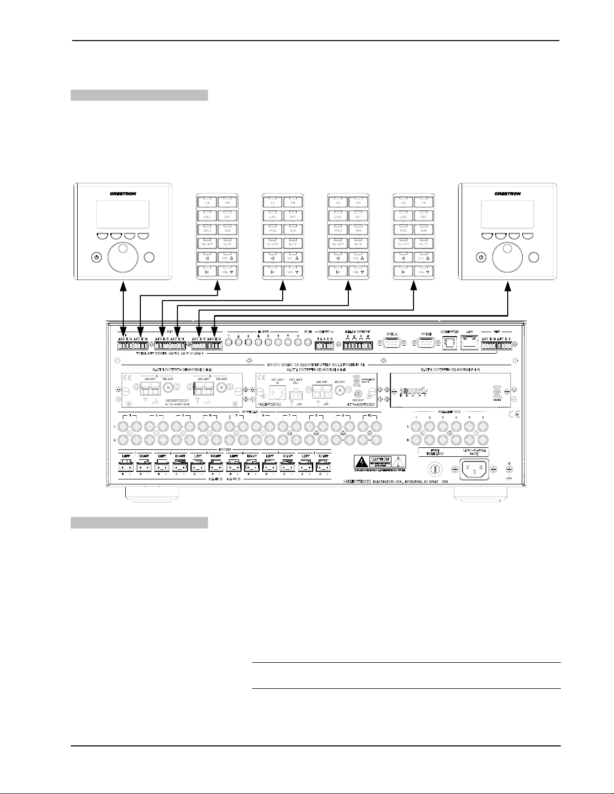
Applications
The following diagram shows an AES as the centerpiece of an Adagio system using
out-of-the-box functionality.
AES as the Centerpiece of an Adagio System
Operations Guide – DOC. 6456B Entertainment System: Adagio AES • 3
Page 8

Entertainment System Crestron Adagio™ AES
Available models are:
• AES: AES with ATC-AMFM2 Tuner Card
• AES-XM: AES with ATC-AMFMXM Tuner Card
• AES-SR: AES with ATC-AMFMSR Tuner Card (available soon)
• AESI: AES for International (230 VAC) use with ATC-AMFM2 Tuner
Card
Out of the box, the AES can support one AAS (Adagio Audio Server), one AAE
(Adagio Audio Expander) for control of up to 12 zones, one CEN-IDOC (Interface
for Apple iPod®), and a combination of up to 12 C2N-DBF12 (12-button keypads) or
APAD controllers for local control of each zone.
With custom programming (via Adagio Composer, Crestron SystemBuilder™ , or
SIMPL™ Windows
®
) and additional AAEs, the AES can control up to 24 zones of
audio. Additional APADS, C2N-DBF12s, CEN-IDOCs and AAS devices can also be
added as well as other Crestron peripherals.
Specifications
Specifications for the AES are listed in the following table.
AES Specifications
SPECIFICATION DETAILS
Processor
CPU
Processing Speed
Memory 8MB Flash, 32MB SDRAM, 256KB NVRAM
Operating System
Ethernet
Audio Specifications
(Typical of six room outputs)
Controls
Preamplifier Output
Frequency Response
Volume Range
Bass Range (100Hz)
Treble Range (10kHz)
Total Harmonic Distortion
(THD)
32-bit Freescale ColdFire
66 MIPS (Dhrystone 2.1 Benchmark)
Real-time, preemptive, multitasking kernel,
multi-threaded, FAT32 file system with long
names; supports SIMPL Windows and
SIMPL+
10/100BaseT, static IP or DHCP/DNS, SSL,
autonegotiating, full duplex TCP/IP,
UDP/IP, SMTP, SNMP, built-in Web server
and e-mail client; supports Crestron
e-Control®2 XPanel and RoomView®
applications
Volume, Balance, Bass, Treble, Loudness,
Mute, Mono, Input Compensation
(6) unbalanced line-level audio outputs;
Selectable for variable or fixed level;
20Hz to 20kHz ±0.2dB
-80dB to +20dB, 1dB steps
±12dB @100Hz, 2dB steps
±12dB @10kHz, 2dB steps
< 0.05%
®
®
Microprocessor
(Continued on following page)
4 • Entertainment System: Adagio AES Operations Guide – DOC. 6456B
Page 9

Crestron Adagio™ AES Entertainment System
AES Specifications (Continued)
SPECIFICATION DETAILS
Audio Specifications (Continued)
Signal-to-Noise Ratio
(SNR)
Stereo Separation
Mute
Maximum Output
Output Impedance:
Amplifier Output
Power
Frequency Response
Signal-to-Noise Ratio
(SNR)
Total Harmonic Distortion
(THD)
Stereo Separation
Inputs
Audio
Maximum Input
Input Impedance
Input Compensation
Tuner Card Slots
Infrared
Digital
Input Impedance
Logic Threshold
Outputs
Infrared/Serial
IR output
> 100dB
>80dB
-100dB (electronic),
-120dB (relay)
2.5 V
100 Ohms
45 Watts into 8 Ohms
60 Watts into 4 Ohms
20Hz to 20kHz ±0.75dB
100dB
0.05%
> 75dB
(10) unbalanced stereo line-level audio
inputs with parallel loop-thrus; connect to
outputs of sources, with loop-thru to AAE;
Inputs 1 through 6 reserved for optional
tuner cards (if installed)
3.2 V
47k Ohms
±10dB
(3) Reserved for optional:
(1) mini-phone jack; For connection of the
CNXRMIRD IR detector (sold separately);
Allows IR wireless control from third-party
universal remotes using RC-5 IR
commands
(4) digital inputs; Rated for 0-24V DC,
referenced to GND;
2.2k ohms pulled up to 5V DC
2.5V DC nominal
(8) mini-phone jack, IR/Serial port;
Up to 1.2 MHz
rms
(flat)
rms
• ATC-AMFM2 Adagio Dual AM/FM
Tuner Card
• ATC-AMFMXM Adagio AM/FM and
XM Satellite Radio Tuner Card
• ATC-AMFMSR Adagio AM/FM and
SIRIUS Satellite Radio Tuner Card
(Continued on following page)
Operations Guide – DOC. 6456B Entertainment System: Adagio AES • 5
Page 10

Entertainment System Crestron Adagio™ AES
AES Specifications (Continued)
SPECIFICATION DETAILS
Outputs (continued)
Serial output
Relay
Rating
Communication
Cresnet®
Serial
Console
Ethernet
Power
Internal Power Supply
AES/AES-XM/AES-SR
AESI
Available Cresnet Power
Heat Dissipation*
8-ohm impedance
4-ohm impedance
LCD Display
Environmental
Temperature
Humidity
Enclosure
Dimensions
Height
Width
Depth
Weight 43 lb (19.5 kg)
One-way serial TTL/RS-232 (0-5V) up to
9600 baud
(4) Normally open, isolated relays;
1A, 30V AC/DC; MOV arc suppression
across contacts
(6) Cresnet Master ports, provide data and
power for C2N-DBF12 keypads and APAD
devices
(2) Cresnet Master ports, paralleled with six
Cresnet ports previously described, provide
data to connected Adagio Audio Expanders
(AAE)
(2) DB9, male, bidirectional RS-232 ports;
Up to 115.2k baud, hardware and software
handshaking support for communication
with serial devices
(1) RJ-11 female, bidirectional RS-232
computer console port for connection to PC
(1) USB 1.1 (Type B female) computer
console port for connection to PC
(1) RJ-45 port for Ethernet communications
7 Amps, 120 Volts AC @ 60Hz
3.5 Amps, 230 Volts AC @ 50Hz
20 Watts (0.83 Amps @ 24 Volts DC)
650 BTU/hr
750 BTU/hr
Green LCD dot matrix, 128 x 64 resolution,
adjustable LED backlight
41° to 104°F (5° to 40°C)
10% to 90% RH (non-condensing)
Black metal with molded ABS/PC front
panel
7.39 in (18.78 cm)
17.16 in (43.58 cm)
18.60 in (47.24 cm)
* BTU/hr ratings made while all channels loaded to 1/8 full power with specified impedance.
(Continued on following page)
6 • Entertainment System: Adagio AES Operations Guide – DOC. 6456B
Page 11

Crestron Adagio™ AES Entertainment System
AES Specifications (Continued)
SPECIFICATION DETAILS
Available Models
AES
AES-XM
AES-SR
AESI
Available Accessories:
APAD
ATC-AMFM2
ATC-AMFMXM
ATC-AMFMSR
AAE
AAS
CEN-IDOC
C2N-DBF12
CNXRMIRD
STIRP
CNSP-XX
C2N-TXM-C50
AES with ATC-AMFM2 Dual AM/FM Tuner
Card
AES with ATC-AMFMXM AM/FM and XM
Satellite Radio Tuner Card
AES with ATC-AMFMSR AM/FM and
SIRIUS Satellite Radio Tuner Card
AES for International (230 VAC) use with
ATC-AMFM2 Dual AM/FM Tuner Card
Wall Mount LCD Controller
Adagio Dual AM/FM Tuner Card
Adagio AM/FM and XM Satellite Radio
Tuner Card
Adagio AM/FM and SIRIUS® Satellite Radio
Tuner Card
Adagio Audio Expander
Adagio Audio Server
Interface for Apple iPod®
12-Button Decorator Keypad
IR Receiver
IR Probe
Custom Serial Interface Cable
XM Antenna Extension Cable
Operations Guide – DOC. 6456B Entertainment System: Adagio AES • 7
Page 12

Entertainment System Crestron Adagio™ AES
Physical Description
This section provides information on the connections, controls, and indicators
available on your AES.
AES Physical View (Front)
AES Physical View (Rear), Shown with ATC-AMFM2 Adagio AM/FM Dual Tuner Card and ATC-AMFMXM Adagio AM/FM
and XM Satellite Radio Tuner Card
8 • Entertainment System: Adagio AES Operations Guide – DOC. 6456B
Page 13

Crestron Adagio™ AES Entertainment System
AES Overall Dimensions
17.09 in
(43.41 cm)
(43.58 cm)
17.56 in
(44.60 cm)
18.60 in
(47.24 cm)
17.16 in
6.78 in
(17.22 cm)
7.39 in
(18.78 cm)
18.23 in
(46.30 cm)
17.93 in
(45.55 cm)
NOTE: Cable connections can extend the overall depth of the AES by
approximately two to three inches.
Operations Guide – DOC. 6456B Entertainment System: Adagio AES • 9
Page 14

Entertainment System Crestron Adagio™ AES
AES Buttons and Ports
8
1
2
3
4
5
6
23 27 28 29 30 31
7
9
10
14
11
15
12 20
13
16
19
17
18
32 33
21
22
34
24
25
26
Connectors, Controls, & Indicators
# CONNECTORS,
CONTROLS, &
INDICATORS
1
SELECTION KNOB
35
36
DESCRIPTION
Used to select rooms, sources, and radio
stations (when using tuner).
(Continued on following page)
10 • Entertainment System: Adagio AES Operations Guide – DOC. 6456B
Page 15

Crestron Adagio™ AES Entertainment System
Connectors, Controls, & Indicators (Continued)
# CONNECTORS,
CONTROLS, &
INDICATORS
2 ENTER BUTTON
3 STANDBY BUTTON
4 LABEL ACCESS
5 HARDWARE RESET
6 SOFTWARE RESET
7 LABEL STRIP COVER
8 SOURCE BUTTON
9 ROOM BUTTON
10 HOUSE BUTTON
11 MENU BUTTON
12 ROOM BUTTONS
13
14 SOFT BUTTONS
LIQUID CRYSTAL
DISPLAY
DESCRIPTION
The ENTER button confirms changes
made to AES settings.
The STANDBY button places the unit in
Standby. The button is lit when the AES is
in use. When in Standby, the button will
not be lit, all switching connections are
broken, and all of the amplifier and preamplifier outputs are powered off. Turning
on a room turns on the AES.
A notch in the front panel allows removal
of the label cover (and access to the USB
port, # 15) with a flat-head screwdriver.
Recessed below the front panel. Press
this button to initiate a system hardware
reset. This has the same effect as
disconnecting and reconnecting power.
Recessed below the front panel. Press
this button while the system is running to
restart the program without rebooting the
processor. Hold during reboot to bypass
the custom program and run the built-in
out-of-the-box functionality.
Covers the engraved label strip and the
USB port (#15).
The SOURCE button places the AES in
the Source mode.
The ROOM button places the AES in the
Room mode.
Functions controlled by the HOUSE button
are determined in a custom program
created by SystemBuilder.
The MENU button returns the display
(#13) to the previous screen.
Room buttons select and indicate the
room(s) controlled by the AES. Room
buttons also indicate rooms contained in a
room group.
The Liquid Crystal Display (LCD) shows
system information such as audio controls,
tuner controls, and room controls.
Function of soft buttons are dependent on
operation of AES.
(Continued on following page)
Operations Guide – DOC. 6456B Entertainment System: Adagio AES • 11
Page 16

Entertainment System Crestron Adagio™ AES
Connectors, Controls, & Indicators (Continued)
# CONNECTORS,
CONTROLS, &
INDICATORS
15 USB PORT
16 BKLT
17 SCHED
18 DISPLAY
19 MORE
20
21
22 MUTE BUTTON
PRESET GROUP
BUTTONS
VOLUME CONTROL
KNOB
DESCRIPTION
Hidden behind the label cover is a USB
port for PC communications. Requires a
standard PC-to-USB-device cable
(included).
The BKLT button adjusts the display and
key backlighting to one of 3 levels (high,
medium, low).
The SCHED button places the AES in the
Schedule mode which is programmed in
SystemBuilder.
The DISPLAY button toggles the
information shown on the display (i.e.
artist and/or song title).
The MORE button displays additional
controls for the SOFT BUTTONS (if
available).
Used to select preset groups.
Turn clockwise to raise the volume of a
room; turn counterclockwise to lower the
volume of a room. Turning the volume
control slowly will adjust the volume level
in fine increments while turning the volume
control quickly will adjust the volume level
in larger increments. Volume level is
displayed on the LCD. Operates in Room
mode only.
The MUTE button is used to mute or
unmute the currently selected room. When
lit, the selected room is muted.
23 NET 1-6
24
(Continued on following page)
12 • Entertainment System: Adagio AES Operations Guide – DOC. 6456B
CARD SLOTS 1-3
(SLOT 1 SHOWN WITH
ATC-AMFM2 INSTALLED)
(6) Four-pin terminal blocks provide home
run Cresnet
power and Cresnet data to rooms for
keypads and/or APADs. Four-pin terminal
block interface connectors are included for
each port.
(3) Slots for optional ATC-AMFM2,
ATC-AMFMXM, and ATC-AMFMSR tuner
cards. A card installed in slot 1 will drive
source input ports 1 and 2. A card
installed in slot 2 will drive source input
ports 3 and 4. A card installed in slot 3 will
drive source input ports 5 and 6. Any input
sources driven by a tuner card cannot be
connected to other input devices.
®
connections to distribute
Page 17

Crestron Adagio™ AES Entertainment System
Connectors, Controls, & Indicators (Continued)
# CONNECTORS,
CONTROLS, &
INDICATORS
25 SOURCES
26 ROOMS
27 IR OUT
DESCRIPTION
(10) Sets of unbalanced, line-level audio
inputs with loop through output. Inputs 1
through 6 are driven by tuner cards
installed in slots 1 through 3 (#24) and
cannot be used by external sources when
tuner cards are installed. Refer to “Adagio
Tuner Cards” on page 20 for information
on which input ports are reserved for
which card slot.
(6) Sets of speaker-level, mono/stereo
outputs provide 45 watts per channel into
8-ohm impedance speakers (60 watts into
4-ohm impedance speakers). Two-pin
terminal block interface connectors which
accept up to 12 AWG (4.0 mm2) speaker
wire are included for each speaker
terminal.
(8) 3.5 mm tip-ring-sleeve (TRS) miniphone ports enable serial communication
in a variety of formats including infrared
and one-way RS-232; Use Crestron
Infrared Emitter Probe (part number
STIRP, sold separately) for controlling
infrared devices. For information on other
serial control cables, contact Crestron.
28 IR IN
29 INPUT
(Continued on following page)
Tip
Ring
Sleeve
Tip: IR Data Out
Ring: No Connection
Sleeve: Ground
(1) 3.5 mm TRS mini-phone port allows IR
wireless control from third-party universal
remotes (via Crestron IR Receiver
CNXRMIRD) using RC-5 IR commands.
Tip
Ring
Sleeve
Tip: IR Data In
Ring: +5 VDC
Sleeve: Ground
(4) Digital inputs. Connect to 24 VDC
(max) logic output or contact closure from
external devices. A five-pin terminal block
interface connector is included.
Operations Guide – DOC. 6456B Entertainment System: Adagio AES • 13
Page 18

Entertainment System Crestron Adagio™ AES
Connectors, Controls, & Indicators (Continued)
# CONNECTORS,
CONTROLS, &
INDICATORS
30 RELAY OUTPUT
31 COM A & COM B
32 COMPUTER
33 LAN
34 NET
DESCRIPTION
(4) Normally open isolated relays; rated to
1A, 30V (AC/DC) with MOV arc
suppression across contacts for control of
“real world” loads. An eight-pin terminal
block interface connector is included.
(2) DB9, male, bidirectional RS-232 ports;
Up to 115.2k baud with hardware and
software handshaking support for
communication with serial devices. Can
also be used for modem communications.
The following table lists the pin
assignments of the serial ports.
PIN DIRECTION DESCRIPTION
1 To AES (DCD) Data Carrier
2 To AES (RXD) Receive Data
3 From AES (TXD) Transmit Data
4 From AES (DTR) Data Terminal
5 Common (GND) Ground
6 To AES (DSR) Data Set
7 From AES (RTS) Request To
8 To AES (CTS) Clear To Send
9 To AES (RI) Ring Indicator
One 6-pin RJ-11 female, computer
console port. Use with included serial
cable.
Pin 1: CTS
Pin 2: GND
Pin 3: RXD
Pin 4: TXD
Pin 5: RTS
Pin 6: N/C (Not connected)
One 8-wire, RJ-45 female connector with
two LED indicators. The green LED
indicates link status while the yellow LED
indicates Ethernet activity. The port
supports 10BaseT/100BaseTX Ethernet
communications.
(2) Four-pin terminal block connectors
provide Cresnet connections to AAE
devices. A four-pin terminal block interface
connector is included for each port.
Detect
Ready
Ready
Send
(Continued on following page)
14 • Entertainment System: Adagio AES Operations Guide – DOC. 6456B
Page 19

Crestron Adagio™ AES Entertainment System
Connectors, Controls, & Indicators (Continued)
# CONNECTORS,
DESCRIPTION
CONTROLS, &
INDICATORS
35 PRE-AMP OUT
36 POWER INPUT
1. Refer to “Fuse Replacement” on page 21 for additional details.
2. Refer to “Hardware Hookup”, which begins on page 17 for additional cord details.
(6) Unbalanced, line-level audio output
ports associated with each room (RCA
connector). Each port has selectable
electronic volume, tone, balance and
loudness control.
Fuse terminal and power connector.
The AES requires a T8AH-type fuse rated
at 250 Volts1. The AES requires 120 VAC,
50-60 Hz, 7 Amps.
The AESI requires a T4AH-type fuse rated
at 250 Volts1. The AESI requires 230
VAC, 50-60 Hz, 3.5 Amps2.
Operations Guide – DOC. 6456B Entertainment System: Adagio AES • 15
Page 20

Entertainment System Crestron Adagio™ AES
Industry Compliance
This product is Listed to applicable UL Standards and requirements by Underwriters
Laboratories Inc.
(E302724)
As of the date of manufacture, the AES has been tested and found to comply with
specifications for CE marking and standards per EMC and Radiocommunications
Compliance Labelling.
NOTE: This device complies with part 15 of the FCC rules. Operation is subject to
the following two conditions: (1) this device may not cause harmful interference, and
(2) this device must accept any interference received, including interference that may
cause undesired operation.
This equipment has been tested and found to comply with the limits for a Class B
digital device, pursuant to part 15 of the FCC Rules. These limits are designed to
provide reasonable protection against harmful interference in a residential
installation. This equipment generates, uses and can radiate radio frequency energy
and, if not installed and used in accordance with the instructions, may cause harmful
interference to radio communications. However, there is no guarantee that
interference will not occur in a particular installation. If this equipment does cause
harmful interference to radio or television reception, which can be determined by
turning the equipment off and on, the user is encouraged to try to correct the
interference by one or more of the following measures:
Reorient or relocate the receiving antenna.
Increase the separation between the equipment and receiver.
Connect the equipment into an outlet on a circuit different from that to
which the receiver is connected.
Consult the dealer or an experienced radio/TV technician for help.
16 • Entertainment System: Adagio AES Operations Guide – DOC. 6456B
Page 21

Crestron Adagio™ AES Entertainment System
Setup
Network Wiring
When wiring the AAE Adagio Audio Expander, APAD controller, or C2N-DBF12
keypad to the AES, consider the following:
• Use Crestron Certified Wire.
• Use Crestron power supplies for Crestron equipment.
• Provide sufficient power to the system.
CAUTION: Insufficient power can lead to unpredictable results or damage
to the equipment. Please use the Crestron Power Calculator to help calculate
how much power is needed for the system
(http://www.crestron.com/calculators
• For larger networks, Use a Cresnet Hub/Repeater (CNXHUB) to maintain
signal quality
).
Ventilation
Out-of-the-box Connections
For more details, refer to “Check Network Wiring” on page 71.
Hardware Hookup
The AES should be used in a well-ventilated area. Do not block any ventilation
openings. The venting holes should not be obstructed under any circumstances. If the
AES is hot to the touch, consider using forced air ventilation and/or incrementing the
spacing between units.
To prevent overheating, do not operate this product in an area that exceeds the
environmental temperature range listed in the table of specifications. Consideration
must be given if installed in a closed or multi-unit rack assembly since the operating
ambient temperature of the rack environment may be greater than the room ambient.
Contact with thermal insulating materials should be avoided on all sides of the unit.
WARNING: To prevent injury and / or equipment damage due to electric shock,
disconnect power from the AES prior to making any wiring connections.
When using the out-of-the-box functionality, the AES can support up to two tuner
cards, one AAE, one CEN-IDOC, one AAS-1/-2/-4, and any combination of six
APAD or C2N-DBF12 control devices (plus an additional six on the AAE if
connected). Observe the following when connecting hardware to the AES.
• Tuner Cards (Optional): Tuner cards must be installed in slots 1 and 2. In
the out-of-the-box configuration, a card cannot be installed in slot 3. Source
input ports 1 and 2 are unavailable for other sources when a tuner card is
installed in slot 1. Source input ports 3 and 4 are unavailable for other
sources when a tuner card is installed in slot 2. For information on
connecting antennas to a tuner card, refer to the respective tuner card’s
guide.
NOTE: If the AES is powered down and the tuner card(s) are changed, the
previously saved source names will be assigned to the new card when the
Operations Guide – DOC. 6456B Entertainment System: Adagio AES • 17
Page 22

Entertainment System Crestron Adagio™ AES
AES is powered. For example, if an ATC-AMFMXM card has been
replaced with an ATC-AMFMSR card, the AES will retain the source
names (i.e. AM, FM, XM, or custom) that were assigned to the
ATC-AMFMXM card. To have the AES recognize the new cards and use
the default source names (S1 AM/FM, S1 XM, etc.), restore the default
settings as described on page 31.
• CEN-IDOC (Optional): The audio output of the CEN-IDOC must be
connected to source input port 5 on the AES when using the out-of-the-box
configuration. The CEN-IDOC and AES must be connected to the same
DHCP router.
• AAS Devices (Optional): Source input ports 7 through 10 are reserved for
the different variations of the AAS. The AAS and AES must be connected
to the same DHCP router.
⇒
AAS-1: The audio output of the AAS-1 must be connected to source
input port 7.
⇒
AAS-2: Audio output A of the AAS-2 must be connected to source
input port 7 and audio output B must be connected to source input port
8.
⇒
AAS-4: Audio output A of the AAS-4 must be connected to source
input port 7. Audio output B must be connected to source input port 8.
Audio output C must be connected to source input port 9, and audio
output D must be connected to source input port 10.
• Control Devices (Optional): Any combination of six APADs or
C2N-DBF12 devices can be connected to any of the six NET ports on the
rear of the AES. If an AAE is connected, six more APADs or C2N-DBF12
devices can be connected.
• AAE (Optional): One AAE can be connected to the AES’ loop-through
ports.
NOTE: The AAE must be set to its default Net ID value (31). For
information on setting the AAE’s Net ID, refer to the latest version of the
AAE guide (Doc. 6460) which is available from the Crestron website.
The connections shown in the following diagram must be made for the AES to
properly control and switch connected devices when using the out-of-the-box
functionality.
CAUTION: Speakers must be rated to full available output.
CAUTION: Do not bridge speaker outputs.
CAUTION: All tuner cards should be securely installed in the AES.
CAUTION: Devices such as the AAS and the AAE must be fully grounded to the
AES. Additionally, any other source devices should be grounded to the AES as well.
NOTE: The AES can only be powered by the included power cord. Power cannot
be supplied from network devices that are connected to the mini-terminal block
connectors.
18 • Entertainment System: Adagio AES Operations Guide – DOC. 6456B
Page 23

Crestron Adagio™ AES Entertainment System
NOTE: The AESI (International version) requires a power cord that is harmonized
to the country’s national and local electrical code. Each inner wire in the cord should
be at least 16 AWG or (1.5 mm
of the cord should be at least 60ºC. The cord length should be 1.5 meters to 2 meters.
Hardware Connections for Out-of-the-Box Functionality (Shown with Tuner Cards in Slots 1 & 2)
INPUT(S)
FROM AAS (OPTIONAL):
AAS-1: SOURCE 7
AAS-2: SOURCES 7 & 8
AAS-4: SOURCES 7-10
INPUT FROM
CEN-IPOD
(OPTIONAL)
OUTPUT TO
CORRESPONDING
SOURCE INPUTS
ON AAE
(IF INSTALLED)
APAD
EACH PAIR OF SPEAKER OUTPUTS CORRESPONDS TO A ROOM NU MBER.
C2N-DBF12 C2N-DBF12 C2N-DBF12 C2N-DBF12
TO ROOM SPEAKERS:
2
) and rated for at least 500V.The temperature rating
APAD
NET:
TO AAE
(OPTIONAL)
LAN:
CONNECT TO DHCP ROUTER;
REQUIRED FOR USE WITH
CEN-IPOD and AAS
GROUND:
TIE ALL SOURCE AND AAE
GROUNDS TO AES
GROUND TERMINAL
POWER:
FROM LINE
VOLTAGE
Custom Program
Refer to the following when not using the out-of-the-box functionality:
Connections
WARNING: To prevent injury and / or equipment damage due to electric shock,
disconnect power from the AES prior to making any wiring connections.
Make the necessary connections as called out in the illustration that follows this
paragraph. Refer to “Network Wiring” on page 17 before attaching the 4-position
terminal block connectors. Apply power after all connections have been made.
CAUTION: Speakers must be rated to full available output.
CAUTION: Do not bridge speaker outputs.
CAUTION: All tuner cards should be securely installed in the AES.
CAUTION: Devices such as the AAS and the AAE must be fully grounded to the
AES. Additionally, any other source devices should be grounded to the AES as well.
Operations Guide – DOC. 6456B Entertainment System: Adagio AES • 19
Page 24

Entertainment System Crestron Adagio™ AES
NOTE: The AES can only be powered by the included power cord. Power cannot
be supplied from network devices that are connected to the mini-terminal block
connectors.
NOTE: The AESI (International version) requires a power cord that is harmonized
to the country’s national and local electrical code. Each inner wire in the cord should
be at least 16 AWG or (1.5 mm
of the cord should be at least 60ºC. The cord length should be 1.5 meters to 2 meters.
Custom Program Connections for the AES (Shown with Tuner Cards in Slots 1 & 2)
IR OUT:
TO STIRP IR EMITTER PROBE
or ONE-WAY SERI AL
CONTROLLED DEVICES
NET:
POWERED PASS-
THROUGH TO APAD and
C2N-DBF12 DEVICES
IR IN:
FROM
CNXRMIRD IR
RECEIVER
INPUT:
FROM DEVICE OUTPUTS
CONTACT OR RELAY CLOSURES
(24 VOLTS MAX)
RELAY OUTPUT:
TO CONTROLLABLE
DEVICES
2
) and rated for at least 500V.The temperature rating
COM A & COM B:
BI-DIRECTIONAL RS-232 WITH
HARDWARE & SOFTWARE
HANDSHAKING AND MODEM CONTROL
COMPUTER:
TO PC
LAN:
10/100 BASE-T
ETHERNET TO LAN
NET:
TO AAE(s)
SOURCES:
FROM AUDIO SOURCES
Adagio Tuner Cards
ROOMS:
45 WATTS/CHANNEL TO
8 OHM SPEAKERS
PRE-AMP OUT (RCA):
CARRIES LINE-LEVEL
UNBALANCED AUDIO.
FOLLOWS SPEAKER OUTPUTS
POWER:
FROM LINE
VOLTAGE
GROUND:
TIE ALL SOURCE AND AAE
GROUNDS TO AES
GROUND TERMINAL
NOTE: A USB port is concealed behind the label cover on the front panel. The USB
port is used to connect with a PC and provides a console connection to the AES.
If optional Adagio tuner cards are installed, refer to the latest version of the
respective tuner card’s Installation Guide for information on connecting the required
antenna(s).
WARNING: Tuner cards must not be installed or removed when the AES is
connected to AC power. Failure to disconnect AC power prior to installing or
removing tuning cards may damage the AES or the tuner card(s).
NOTE: If using the AES’ out-of-the-box functionality, only two tuner cards can be
installed. The tuner cards must be installed in slots 1 and 2.
Source input ports 1 and 2 are unavailable for other sources when a tuner card is
installed in slot 1. Source input ports 3 and 4 are unavailable for other sources when
a tuner card is installed in slot 2. Source input ports 5 and 6 are unavailable for other
sources when a tuner card is installed in slot 3.
When tuner cards are installed in an AES that is connected to an AAE, loop-through
output ports 1 through 6 on the AES are connected to source input ports 1 through 6
on the AAE.
20 • Entertainment System: Adagio AES Operations Guide – DOC. 6456B
Page 25
Crestron Adagio™ AES Entertainment System
AES Control Devices
AES with Control Devices
Any combination of six AES control devices such as the APAD or the C2N-DBF12
can be simultaneously connected to the powered NET ports located on the upper-left
side of the rear panel. Refer to the following diagram and “Network Wiring” on page
17 for wiring information when connecting either APAD devices or C2N-DBF12
keypads.
APADAPAD
C2N-DBF12 C2N-DBF12 C2N-DBF12 C2N-DBF12
Fuse Replacement
If the AES does not power up when it is plugged into an AC outlet, the fuse may
need to be replaced. The fuse holder is located on bottom-right of the rear panel
(next to the power cord connector). To replace the fuse:
• Press STANDBY to place the unit in Standby.
• Disconnect power to the AES.
• Use a flat-head screwdriver to push in the fuse holder.
• While pushing in the fuse holder, turn screwdriver counterclockwise until
the fuse holder pops out.
• Remove the fuse from the fuse holder and insert a new fuse.
CAUTION: Only use the specified type of fuse when replacing a blown
fuse. Failure to do so may cause damage to the AES.
Operations Guide – DOC. 6456B Entertainment System: Adagio AES • 21
Page 26

Entertainment System Crestron Adagio™ AES
Room & Preset Group Button
Labels
AES MODEL REQUIRED FUSE TYPE
AES
(US & Canada)
AESI
(International/230VAC)
T8AH (¼” x 1¼”, 250V, 8A,
time-lag, high-rupture rated)
T4AH (5mm x 20mm, 250V, 4A,
time-lag, high-rupture rated)
• Insert the fuse holder into the AES.
• Push in the fuse holder with a flat head screwdriver. While pushing in the
fuse holder, turn the screwdriver clockwise until the fuse holder sinks in.
• Push in the fuse holder a little further and turn the screwdriver clockwise
until the fuse holder locks in place.
• Connect power to the AES.
Use Adagio Composer or Crestron Engraver software to create and print custom
labels on overhead transparency film for the AES’ room buttons and preset group
buttons.
NOTE: When printing custom labels, some experimentation may be required for
optimum results.
Custom-engraved labels can also be ordered from Crestron. Contact Crestron for
more information.
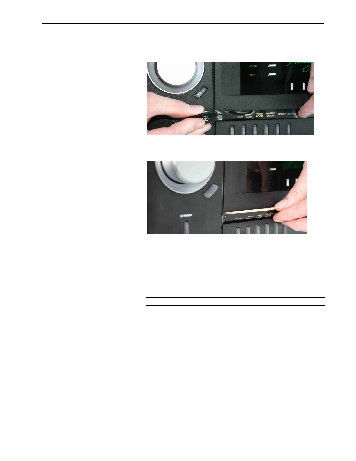
To remove the label:
1. Remove the label cover with a small, flat-head screwdriver. The label cover
is magnetically attached to the front panel of the Adagio component. The
label strip will be exposed.
2. Insert the screwdriver behind the label strip as shown in the diagram below.
22 • Entertainment System: Adagio AES Operations Guide – DOC. 6456B
Page 27
Crestron Adagio™ AES Entertainment System
3. Continue sliding the screwdriver behind the label strip until the top of the
label strip slides out as shown below.
4. Continue sliding the screwdriver until the entire top of the label strip is
visible. Remove the label strip by pulling the top of the label strip up from
the Adagio component as shown in the following picture.
To install the new label:
• Engraved Label Cover: Place the engraved label cover over the label area of
the Adagio component until the label cover’s integrated magnets snap the
label cover into place.
• Printed Label: Place the bottom of the label strip into the Adagio
component. Bend the label strip and position the top of the label strip into
the Adagio component. Replace the label cover over the new label strip.
NOTE: Observe proper orientation so the letters are right-side up.
Operations Guide – DOC. 6456B Entertainment System: Adagio AES • 23
Page 28

Entertainment System Crestron Adagio™ AES
Configuration
After making all hardware connections to the AES, the system must be configured
for operation.
Configuring the system is broken down into four processes:
• Configure the AES for Operation
• Configure Sources
• Configure Rooms
• Configure Preset Groups
Configure the AES for Operation
The AES must be configured for operation prior to configuring sources, rooms, or
groups. Use the Installer Tools to configure the AES for operation.
NOTE: If a custom program was created with Adagio Composer or SystemBuilder,
the following is not required.
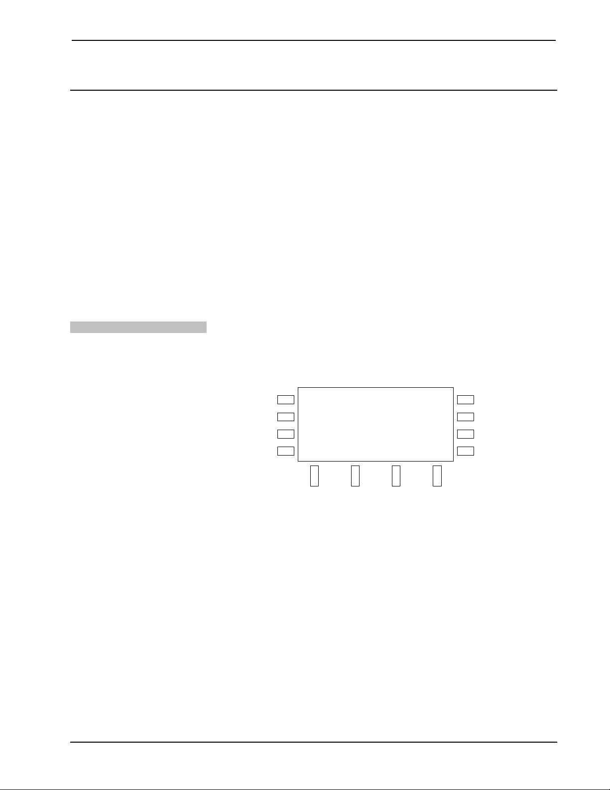
Open Installer Tools
• Press and hold the ROOM and SOURCE buttons for 10 seconds to open
the Installer Tools menu.
Installer Tools Menu
SOURCE
ROOM
HOUSE
MENU
Installer Tools
Select Tuner Format
Configure Network
Set Number of Rooms
BKLT
SCHED
DISPLAY
MORE
• Scroll through the list of available options using the selection knob. The
selected option will be underlined. Available options are:
⇒
Select Tuner Format – Specifies the North American or European
tuning format when using a tuner card.
⇒
Configure Network – Configures the AES to communicate with
devices that are connected to the AES over Ethernet.
⇒
Set Number of Rooms – Sets the number of rooms to be controlled
by the AES.
⇒
Name Rooms – Allows custom naming of rooms controlled by the
AES.
⇒
Name Sources – Allows custom naming of audio sources
connected to the AES.
⇒
Hide Sources – Allows sources to be removed from the source list.
⇒
Identify Keypads – Registers APAD devices and C2N-DBF12
keypads that are connected to the system.
24 • Entertainment System: Adagio AES Operations Guide – DOC. 6456B
Page 29

Crestron Adagio™ AES Entertainment System
⇒ Load APADs – Programs all connected APAD devices to work
with the AES.
⇒
Configure Keypads – Configures the source assignments of the top
six buttons of every C2N-DBF12 keypad that is connected to the
system.
⇒
Restore Defaults – Restores default settings.
⇒
About – Provides information about the AES such as IP data,
firmware version, and program information.
To configure the selected option, press the ENTER button.
To exit Installer Tools and save changes to the AES’ configuration, press
the MENU button.
Select Tuner Format
Select the tuning format to specify the tuning method used by an installed AM/FM
tuner. When using the North American tuner format, the tuner will tune FM
frequencies in 100 kHz steps and AM frequencies in 10 kHz steps. When using the
European tuner format, the tuner will tune FM frequencies in 50 kHz steps and AM
frequencies in 9 kHz steps.
• Open Installer Tools as described on page 24, select Select Tuner Format,
and press the ENTER button
Select Tuner Format Menu
SOURCE
ROOM
HOUSE
MENU
Select Tuner Format
North American
European
BKLT
SCHED
DISPLAY
MORE
• Use the selection knob to select a tuner format. To cancel and return to the
Installer Tools menu, press the MENU button.
• To confirm, press the ENTER button and return to the Installer Tools
menu.
Configure the Network
The AES must be configured to recognize devices that communicate over Ethernet
(i.e. AAS, CEN-IDOC).
• Open Installer Tools as described on page 24, select Configure Network,
and press the ENTER button.
Operations Guide – DOC. 6456B Entertainment System: Adagio AES • 25
Page 30

Entertainment System Crestron Adagio™ AES
Configure Network
SOURCE
ROOM
HOUSE
MENU
Configure Network
Do you want to install
a CEN-IDOC in your
system?
Yes No
BKLT
SCHED
DISPLAY
MORE
• To install a CEN-IDOC, press the soft button labeled Yes and follow the
instructions onscreen. Otherwise, press the soft button labeled No. The
name of the CEN-IDOC will be used in place of “Source 5” in the list of
sources.
• To install an AAS, press the soft button labeled Yes and follow the
instructions onscreen. Otherwise, press the soft button labeled No. The
source names will be renamed as follows:
1,2
1,2
2
⇒
Source 7 becomes “Server 1”
⇒
Source 8 becomes “Server 2”
⇒
Source 9 becomes “Server 3”2
⇒
Source 10 becomes “Server 4”
1: AAS-2 model
2: AAS-4 model
Set the Number of Rooms
NOTE: When installing an AAS, only one AAS can be present on the
network.
• Press MENU to return to the Installer Tools menu.
Set the number of rooms so the AES does not display unused rooms during
configuration and operation.
• Open Installer Tools as described on page 24, select Set Number of
Rooms, and press the ENTER button.
Set the Number of Rooms
SOURCE
ROOM
HOUSE
MENU
Set the Number of Rooms
Select the number of
Rooms that you will
be using:
6
BKLT
SCHED
DISPLAY
MORE
• Use the selection knob to select the number of rooms. To cancel and return
to the Installer Tools menu, press MENU.
• To confirm, press the ENTER button and return to the Installer Tools
menu.
26 • Entertainment System: Adagio AES Operations Guide – DOC. 6456B
Page 31

Crestron Adagio™ AES Entertainment System
Name Rooms
This screen allows you to customize the name of each room displayed on the LCD.
• Open Installer Tools as described on page 24, select Name Rooms, and
press the ENTER button.
Name Rooms
SOURCE
ROOM
HOUSE
MENU
Select Room to Name
1: Room 1
2: Room 2
3: Room 3
Edit
BKLT
SCHED
DISPLAY
MORE
• Turn the selection knob to select the room to be named and press the soft
button labeled Edit (or press the ENTER button). To cancel and return to
the Installer Tools menu, press MENU.
• To use one of the factory-installed names, turn the selection knob clockwise
or counterclockwise to display the desired room name and press ENTER.
• To enter a custom name, turn the selection knob until [Custom Name] is
displayed and press ENTER.
Edit Room Name
Name Sources
SOURCE
ROOM
HOUSE
MENU
Enter Name for Room 1
1: Room 1
2: Room 2
3: Room 3
Del < >
Done
BKLT
SCHED
DISPLAY
MORE
⇒ Select letters (upper and lower-case), numbers, or other characters by
turning the selection knob until the desired letter, number, or other
character is displayed on the LCD. Move the cursor to another position
by pressing the soft buttons labeled g and h. To delete a character,
press the soft button marked Del.
NOTE: The maximum length for any room name is 16 characters.
After entering the new room name, press Done to save the name and
⇒
return to the list of room names.
• If all of the rooms have been named/renamed, press MENU to return to the
Installer Tools menu.
This screen allows you to customize the name of each source displayed on the LCD.
• Open Installer Tools as described on page 24, select Name Sources, and
press the ENTER button.
Operations Guide – DOC. 6456B Entertainment System: Adagio AES • 27
Page 32

Entertainment System Crestron Adagio™ AES
Name Sources
SOURCE
ROOM
HOUSE
MENU
Select Source to Name
1: S1 AM/FM
2: S1 XM
3: Source 3
Edit
BKLT
SCHED
DISPLAY
MORE
• Turn the selection knob to select the source to be named and press the soft
button labeled Edit (or press the ENTER button). To cancel and return to
the Installer Tools menu, press MENU.
• To use one of the factory-installed names, turn the selection knob clockwise
or counterclockwise to display the desired source name and press ENTER.
• To enter a custom name, turn the selection knob until [Custom Name] is
displayed and press ENTER.
Edit Source Name
SOURCE
ROOM
HOUSE
MENU
Enter Name for Src. 1
1: S1 AM/FM
2: S1 XM
3: Source 3
Del < >
Done
BKLT
SCHED
DISPLAY
MORE
Hide Sources
⇒ Select letters (upper and lower-case), numbers, or other characters by
turning the selection knob until the desired letter, number, or other
character is displayed on the LCD. Move the cursor to another position
by pressing the soft buttons labeled g and h. To delete a character,
press the soft button marked Del.
NOTE: The maximum length for any source name is 16 characters.
After entering the new source name, press Done to save the name and
⇒
return to the list of sources.
• If all of the sources have been named/renamed, press MENU to return to
the Installer Tools menu.
This screen allows you to hide sources from the list of available sources. This screen
also allows you to reveal sources that were previously hidden.
• Open Installer Tools as described on page 24, select Hide Sources, and
press the ENTER button.
28 • Entertainment System: Adagio AES Operations Guide – DOC. 6456B
Page 33

Crestron Adagio™ AES Entertainment System
Hide Sources
Identify Keypads
SOURCE
ROOM
HOUSE
MENU
Hide Sources
1: S1 AM/FM
2: S1 XM
3: S2 AM/FM
BKLT
SCHED
DISPLAY
ShowHide
MORE
• To hide a source, turn the selection knob to select the source to be hidden
and press the soft button labeled Hide. Hidden sources are indicated with an
asterisk (*). After all of the sources to be hidden are designated as such,
press MENU to return to the Installer Tools menu.
• To make a source visible, turn the selection knob to select the source to be
made visible and press the soft button labeled Show. After all of the sources
to be shown are designated as such, press MENU to return to the Installer
Tools menu.
This screen allows you to identify keypads and APAD devices that are connected to
the AES.
• Open Installer Tools as described on page 24, select Identify Keypads, and
press the ENTER button.
NOTE: Any attached AAE will automatically be identified by the AES
during this step.
Identify Keypads Warning
SOURCE
ROOM
HOUSE
MENU
Identify Keypads
Warning: All keypads will
need to be re-identified
Continue?
Yes
No
BKLT
SCHED
DISPLAY
MORE
• Press the soft button labeled Yes to proceed and clear previously stored
keypad identification data or press No to cancel.
Select Keypad Type
SOURCE
ROOM
HOUSE
MENU
Identify Keypads
Select keypad type
for Room 1
APAD 12But None
BKLT
SCHED
DISPLAY
MORE
Operations Guide – DOC. 6456B Entertainment System: Adagio AES • 29
Page 34

Entertainment System Crestron Adagio™ AES
• Press the appropriate soft button to select the control device type (APAD or
keypad) for the first room controlled by the AES (Room Output 1). If there
is no control device for that room, press the soft button labeled None.
• Follow the onscreen instructions for identifying the device. After
identifying the device, the AES will prompt for the next room’s control
device.
NOTE: If a device is not identified within two minutes, the AES will
indicate that the keypad was not found. Try again by pressing the soft
button labeled Yes or cancel the process by selecting the soft button labeled
Abort.
• Repeat the procedure until control devices for all of the specified rooms
(refer to page 26) have been identified.
Load APADs
Configure Keypads
APAD devices may need to be programmed to work with the AES. If a connected
APAD does not display controls for the AES, perform the following:
• Open Installer Tools as described on page 24, select Load APADs, and
press the ENTER button.
Load APADs Warning
SOURCE
ROOM
HOUSE
MENU
Warning:
All APADs will be
loaded with default
functionality. Continue?
Yes No
BKLT
SCHED
DISPLAY
MORE
• Press the soft button labeled Yes to proceed and load the required files to
connected APADs or press No to cancel.
This screen allows you to assign sources to the top six keys of a C2N-DBF12
keypad. The source assignment is applied to every C2N-DBF12 keypad that is
connected to the system. The functions of the bottom six keys cannot be changed
when using the out-of-the-box program.
• Open Installer Tools as described on page 24, select Configure Keypads,
and press the ENTER button.
Select Button To Map
SOURCE
ROOM
HOUSE
MENU
Select Button To Map
Btn1: S1 AM/FM
Btn2: S1 XM
Btn3: Source 3
Edit
BKLT
SCHED
DISPLAY
MORE
30 • Entertainment System: Adagio AES Operations Guide – DOC. 6456B
Page 35

Crestron Adagio™ AES Entertainment System
• Turn the selection knob to select the button to be mapped and press the
ENTER button or the soft button labeled Edit. To cancel and return to the
Installer Tools menu, press MENU.
Select Source for Button and Button Layout
SOURCE
ROOM
HOUSE
MENU
Select Src. For Button 1
Btn1: [S1 AM/FM]
Btn2: S1 XM
Btn3: Source 3
BKLT
SCHED
DISPLAY
MORE
BUTTON 1
BUTTON 3
BUTTON 5
BUTTON 2
BUTTON 4
BUTTON 6
• Select the source for the button by turning the selection knob until the
desired source is displayed on the LCD. If a button is not to be used, select
Not Used.
• After selecting the source, press the ENTER button to save the assignment
and return to the list of buttons. If all of the buttons have been
assigned/reassigned, press MENU to return to the Installer Tools menu.
Restore Default Settings
The AES can be restored to its default factory settings from the front panel. All
settings that have been made with Installer Tools, as well as room and source audio
settings will be reset to their factory defaults.
• Open Installer Tools as described on page 24, select Restore Defaults, and
press the ENTER button.
Restore Defaults Warning
SOURCE
ROOM
HOUSE
MENU
Restore Defaults:
All Installer Mode and
room/source audio settings
will be reset. Continue?
Yes No
BKLT
SCHED
DISPLAY
MORE
Operations Guide – DOC. 6456B Entertainment System: Adagio AES • 31
Page 36

Entertainment System Crestron Adagio™ AES
• Press the soft button labeled Yes to proceed and restore the default settings
or press No to cancel.
About
Adjust the Gain of a Source
This screen allows you to view information about the AES.
• Open Installer Tools as described on page 24, select About, and press the
ENTER button. The IP address, IP mask, and Hostname of the AES are
displayed on the LCD.
About
SOURCE
ROOM
HOUSE
MENU
System Information
Addr: 195.168.121.248
Mask: 255.255.255.0
Hostname: AES00107f050025
BKLT
SCHED
DISPLAY
MORE
• Turn the selection knob to display additional information.
Configure Sources
The gain of each source can be customized from the AES control panel.
To adjust a source’s gain:
• Select a source to adjust by pressing SOURCE and using the selection
knob to select a source.
• Press and hold the SOURCE and MORE buttons at the same time to open
the Gain control. The soft button labels will change to show the available
control option.
Source Setup Menu
SOURCE
ROOM
HOUSE
MENU
iPod
Gain 0dB
Reset
BKLT
SCHED
DISPLAY
MORE
• Adjust the gain level with the selection knob. Turn clockwise to raise the
gain level or counterclockwise to lower the gain level. Press the soft button
labeled Reset to set the gain level to 0dB.
• Press MENU to exit.
Configure Rooms
The sound quality, minimum volume, maximum volume and startup volume settings,
of each room can be customized from the AES control panel.
32 • Entertainment System: Adagio AES Operations Guide – DOC. 6456B
Page 37

Crestron Adagio™ AES Entertainment System
Access the Room Setup
Mode
• Select a room to configure by pressing a room button. Alternatively, press
ROOM and select the room with the selection knob.
• Press the ROOM and MORE buttons at the same time to open the Room
Setup menu. The soft button labels will change to show the available
control options.
Room Setup Menu
SOURCE
ROOM
HOUSE
MENU
Room 3
Select Parameter
to Adjust
MinV MaxV StartV Mono
BKLT
SCHED
DISPLAY
MORE
Parameters that can be adjusted include:
⇒
Minimum Volume
⇒
Maximum Volume
⇒
Startup Volume
⇒
Mono/Stereo
Adjust the Minimum Volume
The minimum volume establishes the lowest volume level setting for a room. The
minimum volume settings of each room can be adjusted independently.
• Access the Room Setup mode as described on page 33.
• Press the soft button labeled MinV to open the Minimum Volume control.
Minimum Volume Control
SOURCE
ROOM
HOUSE
MENU
Room 3
Min Volume 30%
Reset
BKLT
SCHED
DISPLAY
MORE
• Adjust the minimum volume with the selection knob. Turn clockwise to
raise the minimum volume or counterclockwise to lower the minimum
volume. The highest minimum volume setting is 30%. Press the soft button
labeled Reset to set the volume level to 0%.
NOTE: Other rooms can be adjusted by pressing a different room button.
• Press MENU to return to the Room Setup menu.
Operations Guide – DOC. 6456B Entertainment System: Adagio AES • 33
Page 38

Entertainment System Crestron Adagio™ AES
Adjust the Maximum Volume
The maximum volume establishes the highest volume level setting for a room. The
maximum volume settings of each room can be adjusted independently.
• Access the Room Setup mode as described on page 33.
• Press the soft button labeled MaxV to open the Maximum Volume control.
Maximum Volume Control
SOURCE
ROOM
HOUSE
MENU
Room 3
Max Volume 70%
Reset
BKLT
SCHED
DISPLAY
MORE
• Adjust the maximum volume with the selection knob. Turn clockwise to
raise the maximum volume or counterclockwise to lower the maximum
volume. The lowest maximum volume setting is 70%. Press the soft button
labeled Reset to set the volume level to 100%.
NOTE: Other rooms can be adjusted by pressing a different room button.
• Press MENU to return to the Room Setup menu.
Adjust the Startup Volume
The startup volume establishes the volume level setting for a room when a room is
turned on. The startup volume settings of each room can be adjusted independently.
• Access the Room Setup mode as described on page 33.
• Press the soft button labeled StartV to open the Startup Volume control.
Startup Volume Control
SOURCE
ROOM
HOUSE
MENU
Room 3
Startup Volume 50%
Reset
BKLT
SCHED
DISPLAY
MORE
• Adjust the startup volume with the selection knob. Turn clockwise to raise
the startup volume or counterclockwise to lower the startup volume. The
maximum startup volume setting is 50%. Press the soft button labeled
Reset to set the volume level to 30%.
NOTE: Other rooms can be adjusted by pressing a different room button.
• Press MENU to return to the Room Setup menu.
34 • Entertainment System: Adagio AES Operations Guide – DOC. 6456B
Page 39

Crestron Adagio™ AES Entertainment System
Set Mono or Stereo Mode
The audio sent to the speakers in each room can be set for either stereo or mono.
When set to stereo, the audio signal is separated into left and right channels for
distribution to left and right speakers. When set to mono, the audio signal is
combined into one signal for use in larger rooms where stereo separation is not
practical. The mono/stereo settings of each room can be adjusted independently.
• Access the Room Setup mode as described on page 33.
• Press the soft button labeled Mono to open the Stereo/Mono control.
Stereo/Mono Control
SOURCE
ROOM
HOUSE
MENU
Room 3
Stereo/Mono
Stereo
Mono
BKLT
SCHED
DISPLAY
MORE
• The selected mode is underlined on the lower-right side of the LCD. Press
the soft button labeled Stereo to select the stereo mode. Press the soft
button labeled Mono to select the mono mode.
NOTE: Other rooms can be adjusted by pressing a different room button.
• Press MENU to return to the Room Setup menu.
Operations Guide – DOC. 6456B Entertainment System: Adagio AES • 35
Page 40

Entertainment System Crestron Adagio™ AES
Configure Preset Groups
Preset groups can be created to group speakers in adjacent rooms with a specified
source, or switch into a whole-house “party” mode, by letting the user link a source
with any number of rooms. Changing the source in any one room changes the source
in all of the rooms in the preset group.
Edit a Preset Group
To edit a preset group:
• Press and hold a preset group button for approximately five seconds to view
the Edit Group controls shown below. The selected preset group button will
flash.
Edit Group Controls
SOURCE
ROOM
HOUSE
MENU
Source: No Source Sele
Name: Group 1
Edit Group 1
BKLT
SCHED
DISPLAY
DoneNameSourceCancel
MORE
• Select the rooms in the preset group by pressing the corresponding room
buttons on the AES or AAE (if connected). Each room button’s LED will
turn on. Press again to remove the room from the preset group. The room
button’s LED will turn off.
• Select a source for the preset group by pressing the soft button labeled
Source. Turn the selection knob clockwise or counterclockwise until the
desired source is displayed on the LCD.
• Press the soft button labeled Name to change the name of the preset group.
The group name controls will be displayed. Select letters (upper and lowercase) by turning the selection knob until the desired letter is displayed.
Move the cursor to another position by pressing the soft buttons labeled g
and h. To delete a character, press the soft button marked Del.
NOTE: The maximum length for any preset group name is 16 characters.
Edit Group Name Controls
SOURCE
ROOM
HOUSE
MENU
Source: No Source Sele
Name: Group 1
Edit Group 1
BKLT
SCHED
DISPLAY
Done><Del
MORE
• After editing the preset group, press Done to save the changes and return to
the previous operating mode.
36 • Entertainment System: Adagio AES Operations Guide – DOC. 6456B
Page 41
Crestron Adagio™ AES Entertainment System
Operation
Prior to using this section, refer to the QuickStart Guide (Doc. 6457) that is included
with the AES.
For instructions on using the APAD and the C2N-DBF12 with the AES refer to the
latest version of the Out-Of-The-Box Functionality Guide (Doc. 6493).
Operating the AES is broken down into three modes:
• Source Mode
• Room Mode
• Turn Off the System
Source Mode
Source mode is used to select and control sources that are connected to the AES. A
selected source can also be routed to any room or rooms connected to the AES or a
connected AAE.
Select a Source
To select a source:
• Press Source to put the AES in Source mode. The current controlled source
is displayed on the LCD.
Source Mode
SOURCE
ROOM
HOUSE
MENU
Control
S1 AM/FM
101.90 FM
Stereo
BKLT
SCHED
DISPLAY
MORE
• Turn the selection knob until the desired source is displayed on the LCD.
Rooms that are connected to the displayed source are indicated on the room
buttons.
• Press the ENTER button (or the soft button labeled Control if it is a device
that can be controlled by the AES) to select and control the source.
When using the out-of-the-box functionality, the AES can control tuner cards
installed in slots 1 and 2, an iPod connected to a CEN-IDOC, and an AAS (when
connected).
Controlling a Tuner
A tuner card installed in either slot one or two can be controlled by the AES front
panel.
The following assumes that a tuner card has been installed in slot one or two (or
both) as described in the tuner card’s guide.
Operations Guide – DOC. 6456B Entertainment System: Adagio AES • 37
Page 42

Entertainment System Crestron Adagio™ AES
Find the Tuner Controls
• Place the AES in the Source mode (see “Select a Source” on page 37).
• Turn the selection knob to the desired tuner source (sources 1 and 2 for a
tuner card installed in slot one, sources 3 and 4 for a tuner card installed in
slot two). The frequency/channel and other information will be displayed.
FM Radio Source
SOURCE
ROOM
HOUSE
MENU
Control
S1 AM/FM
101.90 FM
Stereo
BKLT
SCHED
DISPLAY
MORE
XM Radio Source
SOURCE
ROOM
HOUSE
MENU
Control
S1 XM
The 40's
I can’t believe
BKLT
SCHED
DISPLAY
MORE
SIRIUS Radio Source
SOURCE
ROOM
HOUSE
MENU
Control
S1 SIRIUS
Elvis Radio
All Shook Up
• Press the soft button labeled Control or press ENTER to open the tuner
controls.
BKLT
SCHED
DISPLAY
MORE
38 • Entertainment System: Adagio AES Operations Guide – DOC. 6456B
Page 43
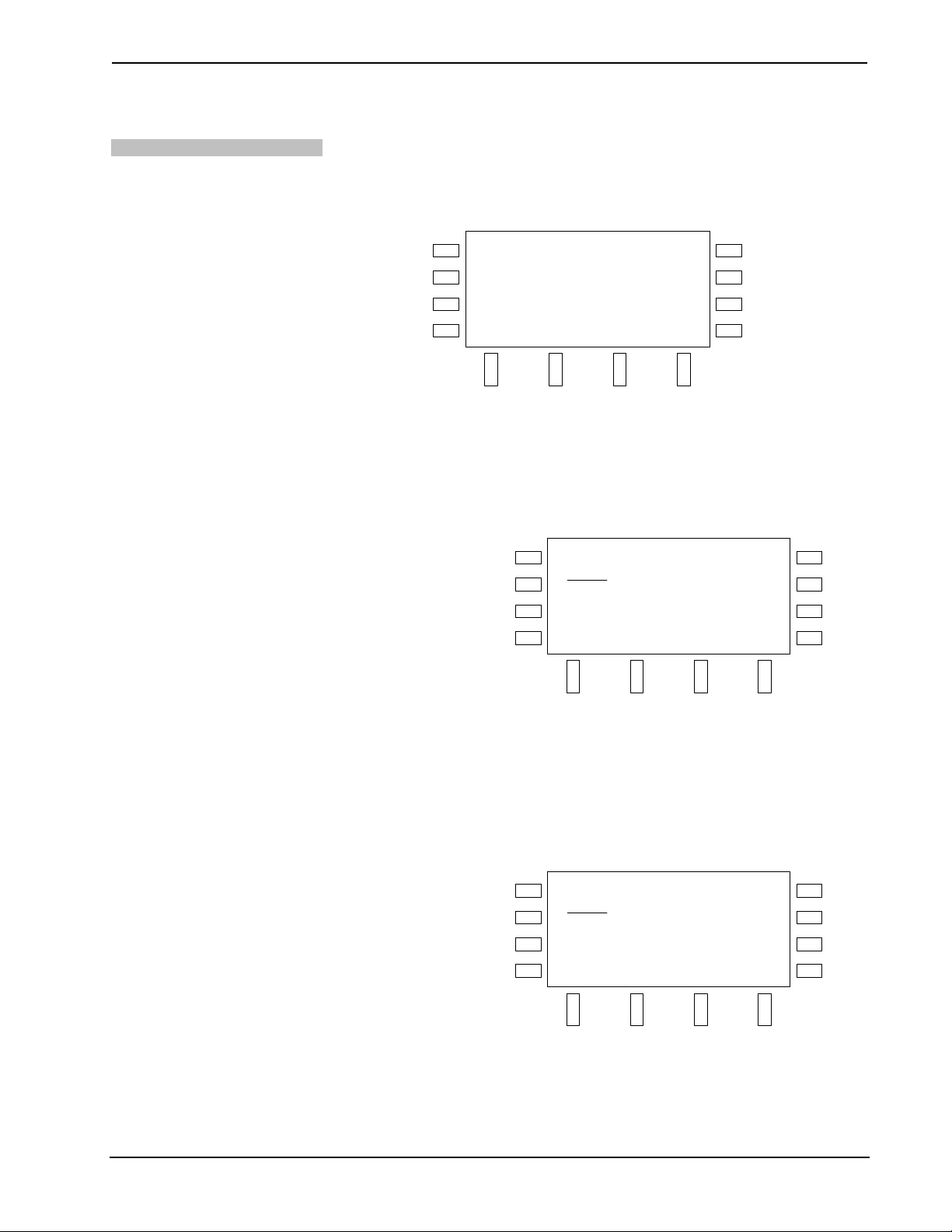
Crestron Adagio™ AES Entertainment System
Control the AM/FM Tuner
The AM/FM tuner controls allow access to the AM/FM tuner functions. The tuner
controls can recall and store presets, tune and scan stations on the frequency band, or
change frequency bands (AM or FM).
AM/FM Controls
SOURCE
ROOM
HOUSE
MENU
101.90 FM Stereo
S1 AM/FM
Preset Manual Tech
BKLT
SCHED
DISPLAY
MORE
• Presets:
Use presets to recall and store favorite stations.
⇒ To recall a preset:
Press the soft button labeled Preset.
Preset Controls
SOURCE
ROOM
HOUSE
MENU
FM Presets
1. 95.50
2. 104.30
3. 101.10
Save
BKLT
SCHED
DISPLAY
MORE
Select a preset location with the selection knob and press the
ENTER button.
⇒ To store a preset:
Tune the desired station using the Manual tuning mode.
Press the soft button labeled Preset.
Preset Controls
SOURCE
ROOM
HOUSE
MENU
FM Presets
1. 95.50
2. 104.30
3. 101.10
Save
Select a preset location with the selection knob and press the
soft button labeled Save.
BKLT
SCHED
DISPLAY
MORE
Operations Guide – DOC. 6456B Entertainment System: Adagio AES • 39
Page 44
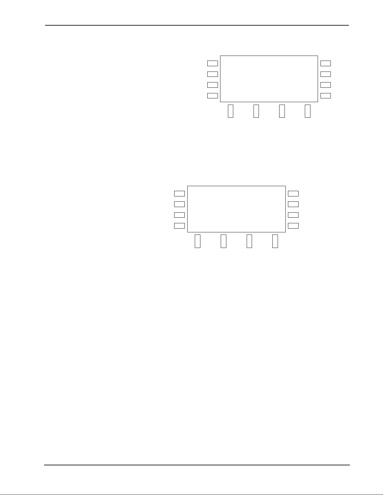
Entertainment System Crestron Adagio™ AES
Replace Preset Prompt
SOURCE
ROOM
HOUSE
MENU
Replace preset with...
100.50 FM
CancelOK
Press the soft button labeled OK to confirm or the soft button
labeled Cancel to cancel.
• Manual Mode:
Press the soft button labeled Manual to operate in the Manual mode.
Manual Mode
SOURCE
ROOM
HOUSE
MENU
101.90 FM Stereo
S1 AM/FM
DCBand
BKLT
SCHED
DISPLAY
MORE
BKLT
SCHED
DISPLAY
MORE
When operating in Manual mode, the tuner can be manually tuned or it can
scan each clear frequency for five seconds before seeking the next clear
frequency. When in Manual mode, the frequency band can also be changed.
⇒
Manual Tuning
Turn the selection knob clockwise to manually increase the
frequency; or turn counterclockwise to manually decrease the
frequency.
⇒
Scanning:
Press the soft button labeled C to start a scan that increases in
frequency; or press the soft button labeled D to start a scan
that decreases in frequency to the next clear frequency.
Stop the scan by pressing either of the scan control buttons.
The scan automatically stops when the tuner reaches the
frequency where the scan originally started.
⇒
Band selection:
To switch between the AM and FM frequency band, press the soft
button labeled Band.
• Signal Strength:
To view the signal strength of the tuned frequency:
⇒
Press the soft button labeled Tech to view the signal strength.
40 • Entertainment System: Adagio AES Operations Guide – DOC. 6456B
Page 45

Crestron Adagio™ AES Entertainment System
Signal Strength (FM Shown)
Control the XM Tuner
SOURCE
FM Signal Strength: 75%
ROOM
HOUSE
MENU
S1 AM/FM
MonoStereo
⇒ To return to the tuner controls, press the MENU button.
The XM tuner controls allow access to XM tuner functions such as presets,
categories, and channels, as well as viewing radio signal strength.
XM Radio Controls
SOURCE
ROOM
The 40's 54
Buddy Clark
BKLT
SCHED
Linda
HOUSE
MENU
S1 XM
Preset Cat Chan Tech
DISPLAY
MORE
BKLT
SCHED
DISPLAY
MORE
• Presets:
Use presets to quickly recall favorite stations.
⇒ To recall a preset:
Press the soft button labeled Preset.
Preset Controls
SOURCE
ROOM
HOUSE
MENU
Presets
12. X Country
6. The 60s
8. The 80s
Select a preset location with the selection knob and press the
ENTER button.
⇒ To store a preset:
Tune the desired station using the Category or Channel
modes.
Press the soft button labeled Preset.
Save
BKLT
SCHED
DISPLAY
MORE
Operations Guide – DOC. 6456B Entertainment System: Adagio AES • 41
Page 46

Entertainment System Crestron Adagio™ AES
Preset Controls
SOURCE
ROOM
HOUSE
MENU
Presets
12. X Country
6. The 60s
8. The 80s
Save
BKLT
SCHED
DISPLAY
MORE
Select a preset location with the selection knob and press the
soft button labeled Save.
Replace Preset Prompt
SOURCE
ROOM
HOUSE
MENU
Replace preset with...
Nashville!
BKLT
SCHED
DISPLAY
CancelOK
MORE
Press the soft button labeled OK to confirm or the soft button
labeled Cancel to cancel.
• Category Mode:
The Category mode lets you select a channel based on a category.
⇒ Press the soft button labeled Cat to view available channel
categories:
Category Controls
SOURCE
ROOM
HOUSE
MENU
⇒
Turn the selection knob to view the list of available categories.
⇒
Press the ENTER button to select a category.
⇒
Turn the selection knob to view the list of channels in the category.
⇒
Press the ENTER button to select a channel.
Categories
Decades
Country
Hits
• Channel Mode:
The Channel mode lets you select a channel based on the channel name.
BKLT
SCHED
DISPLAY
MORE
⇒
Press the soft button labeled Chan to view available channels.
42 • Entertainment System: Adagio AES Operations Guide – DOC. 6456B
Page 47

Crestron Adagio™ AES Entertainment System
Channel Controls
SOURCE
ROOM
HOUSE
MENU
Channels
1. XM Preview
4. The 40s
5. The 50s
⇒ Turn the selection knob to view the list of available channels.
NOTE: Channel 0 displays the radio ID which is required for
subscription to the XM radio service.
Press the ENTER button to select a channel.
⇒
• Technical Section:
The technical section displays repeater and satellite signal strength in
graphic form as well as the radio ID.
Press the soft button labeled Tech to view technical information
⇒
about the XM receiver.
Technical Information
SOURCE
Repeater Signal:
Satellite Signal:
ROOM
HOUSE
MENU
Radio ID: JU12345
S1 XM
BKLT
SCHED
DISPLAY
MORE
BKLT
SCHED
DISPLAY
MORE
⇒ Press the MENU button to return to the XM Radio controls.
Control the SIRIUS Tuner
The SIRIUS tuner controls allow access to SIRIUS tuner functions such as presets,
categories, and channels, as well as viewing radio signal strength.
SIRIUS Radio Controls
SOURCE
ROOM
Elvis Radio 13
Elvis Presley
BKLT
SCHED
All Shook Up
HOUSE
MENU
S1 SIRIUS
Preset Cat Chan Tech
DISPLAY
MORE
• Presets:
Use presets to quickly recall favorite stations.
⇒ To recall a preset, press the soft button labeled Preset.
Operations Guide – DOC. 6456B Entertainment System: Adagio AES • 43
Page 48
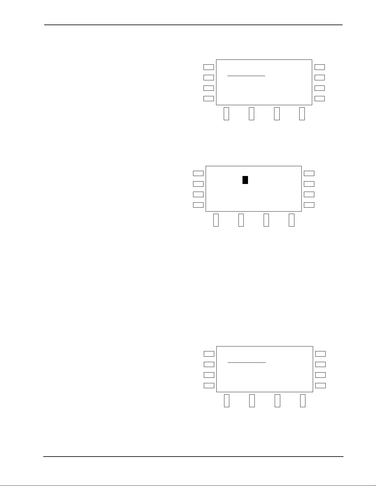
Entertainment System Crestron Adagio™ AES
Preset Controls
SOURCE
ROOM
HOUSE
MENU
Presets
12. Super Shuffle
6. `60s Vibrations
8. Big `80s
SaveClear
⇒ Select a preset location with the selection knob and press the
ENTER button. If the channel is locked, you will be prompted to
enter a Personal Identification Number (PIN).
Enter PIN
SOURCE
ROOM
HOUSE
MENU
S2 SIRIUS
Please Enter PIN
0000
<>
Enter
BKLT
SCHED
DISPLAY
MORE
Enter the first digit of the PIN (the factory default is 1234) by
turning the selection knob clockwise or counterclockwise until
the desired digit is displayed.
BKLT
SCHED
DISPLAY
MORE
Press the soft buttons labeled < or > to move the cursor to the
previous or next digit and enter the rest of the PIN.
When the PIN is displayed, press the soft button labeled
ENTER to unlock the channel.
⇒ To store a preset:
Tune the desired station using the Category or Channel
modes.
Press the soft button labeled Preset.
Preset Controls
SOURCE
ROOM
HOUSE
MENU
Presets
12. Super Shuffle
6. `60s Vibrations
8. Big `80s
Save
Select a preset location with the selection knob and press the
soft button labeled Save.
BKLT
SCHED
DISPLAY
MORE
44 • Entertainment System: Adagio AES Operations Guide – DOC. 6456B
Page 49

Crestron Adagio™ AES Entertainment System
Replace Preset Prompt
SOURCE
ROOM
HOUSE
MENU
Replace preset with...
Classic Vinyl
CancelOK
Press the soft button labeled OK to confirm or the soft button
labeled Cancel to cancel.
⇒ To clear a preset location:
Select a preset with the selection knob and press the soft
button labeled Clear.
Clear Preset
SOURCE
ROOM
HOUSE
MENU
Are you sure
want to clear this
preset?
CancelOK
BKLT
SCHED
DISPLAY
MORE
BKLT
SCHED
DISPLAY
MORE
Press the soft button labeled OK to clear the preset location or
press the soft button labeled Cancel to cancel.
• Category Mode:
The Category mode lets you select a channel based on a category.
⇒ Press the soft button labeled Cat to view available channel
categories:
Category Controls
SOURCE
ROOM
HOUSE
MENU
⇒
Turn the selection knob to view the list of available categories.
⇒
Press the ENTER button to select a category.
⇒
Turn the selection knob to view the list of channels in the category.
Categories
Pop
Rock
Electronic/Dance
BKLT
SCHED
DISPLAY
MORE
Operations Guide – DOC. 6456B Entertainment System: Adagio AES • 45
Page 50

Entertainment System Crestron Adagio™ AES
NOTE: Some channels may be locked or hidden from view. To
select which channels are locked or hidden from view, refer to
“Technical Section” on page 47.
Press the ENTER button to select a channel. If the channel is
⇒
locked, you will be prompted to enter a Personal Identification
Number (PIN).
Enter PIN
SOURCE
ROOM
HOUSE
MENU
S2 SIRIUS
Please Enter PIN
0000
<>
Enter
Enter the first digit of the PIN (the factory default is 1234) by
turning the selection knob clockwise or counterclockwise until
the desired digit is displayed.
Press the soft buttons labeled < or > to move the cursor to the
previous or next digit and enter the rest of the PIN.
When the PIN is displayed, press the soft button labeled
ENTER to unlock the channel.
• Channel Mode:
The Channel mode lets you select a channel based on the channel name.
⇒ Press the soft button labeled Chan to view available channels.
Channel Controls
SOURCE
ROOM
HOUSE
MENU
Channels
1. SIRIUS Hits 1
4. StarLite
5. SIRIUS Love
BKLT
SCHED
DISPLAY
MORE
BKLT
SCHED
DISPLAY
MORE
⇒ Turn the selection knob to view the list of available channels.
NOTE: Some channels may be locked or hidden from view. To
select which channels are locked or hidden from view, refer to
“Technical Section” on page 47.
NOTE: Channel 0 displays the radio ID which is required for
subscription to the SIRIUS radio service.
46 • Entertainment System: Adagio AES Operations Guide – DOC. 6456B
Page 51

Crestron Adagio™ AES Entertainment System
⇒ Press the ENTER button to select a channel. If the channel is
locked, you will be prompted to enter a Personal Identification
Number (PIN).
Enter PIN
SOURCE
ROOM
HOUSE
MENU
S2 SIRIUS
Please Enter PIN
0000
<>
Enter
BKLT
SCHED
DISPLAY
MORE
Enter the first digit of the PIN (the factory default is 1234) by
turning the selection knob clockwise or counterclockwise until
the desired digit is displayed.
Press the soft buttons labeled < or > to move the cursor to the
previous or next digit and enter the rest of the PIN.
When the PIN is displayed, press the soft button labeled
ENTER to unlock the channel.
• Technical Section:
The technical section displays repeater and satellite signal strength in
graphic form as well as the radio ID. The technical information section also
contains controls for viewing SIRIUS tuner information, locking channels
(accessible by entering a Personal Identification Number), hiding/exposing
channels from the channel list (accessible by entering a Personal
Identification Number), and resetting the Personal Identification Number
(PIN).
⇒ Press the soft button labeled Tech to view information about the
repeater signal strength, satellite signal strange, and the radio ID.
Buttons for viewing tuner card information and tuner setup will
also be displayed.
Technical Information
SOURCE
Repeater Signal:
BKLT
Satellite Signal:
ROOM
HOUSE
MENU
Radio ID: 012345678901
S1 SIRIUS
About Setup
SCHED
DISPLAY
MORE
⇒ To view firmware and other information about the tuner card:
Press the soft button labeled About.
Operations Guide – DOC. 6456B Entertainment System: Adagio AES • 47
Page 52

Entertainment System Crestron Adagio™ AES
About
SOURCE
ROOM
HOUSE
MENU
00: 01.07.00 G26 SSP
S2 SIRIUS
About
<>
Press the soft buttons labeled < or > to scroll through the
available information.
Press the MENU button to return to the SIRIUS technology
section controls.
⇒ To hide or unhide channels from the channel listing:
Press the soft button labeled Setup. A prompt to enter a
Personal Identification Number (PIN) will be displayed.
Enter PIN
SOURCE
ROOM
HOUSE
MENU
S2 SIRIUS
Please Enter PIN
0000
<>
Enter
BKLT
SCHED
DISPLAY
MORE
BKLT
SCHED
DISPLAY
MORE
Enter the first digit of the PIN (the factory default is 1234) by
turning the selection knob clockwise or counterclockwise until
the desired digit is displayed.
Press the soft buttons labeled < or > to move the cursor to the
previous or next digit and enter the rest of the PIN.
When the PIN is displayed, press the soft button labeled
ENTER to open the Setup controls.
Setup Controls
SOURCE
ROOM
HOUSE
MENU
Setup
Setup Channels
Change PIN
BKLT
SCHED
DISPLAY
MORE
Turn the selection knob clockwise or counterclockwise to
highlight “Setup Channels” and press the ENTER button to
display a list of all of the SIRIUS channels.
48 • Entertainment System: Adagio AES Operations Guide – DOC. 6456B
Page 53

Crestron Adagio™ AES Entertainment System
Setup Controls—Channel Listing
SOURCE
ROOM
HOUSE
MENU
Setup Channels
1. SIRIUS Hits 1
2. StarLite
3. SIRIUS Love
BKLT
SCHED
DISPLAY
MORE
Turn the selection knob to highlight the channel that is to be
hidden or unhidden and press the ENTER button to open the
Lock/Hide channel controls
Lock/Hide Channel Controls
SOURCE
ROOM
HOUSE
MENU
SIRIUS Hits 1 1
Parental Lock: Off
Hide Channel: No
Lock Hide
BKLT
SCHED
DISPLAY
MORE
If a channel is to be hidden, press the soft button labeled Hide.
If a hidden channel is to be unhidden, press the soft button
labeled Hide.
Press the MENU button to return to the SIRIUS technology
section controls.
⇒ To lock or unlock channels:
Press the soft button labeled Setup. A prompt to enter a
Personal Identification Number (PIN) will be displayed. Enter
the PIN as described on page 48 to open the Setup controls.
Setup Controls
SOURCE
ROOM
HOUSE
MENU
Setup
Setup Channels
Change PIN
Turn the selection knob clockwise or counterclockwise to
highlight “Setup Channels” and press the ENTER button to
display a list of all of the SIRIUS channels.
BKLT
SCHED
DISPLAY
MORE
Operations Guide – DOC. 6456B Entertainment System: Adagio AES • 49
Page 54

Entertainment System Crestron Adagio™ AES
Setup Controls—Channel Listing
SOURCE
ROOM
HOUSE
MENU
Setup Channels
1. SIRIUS Hits 1
2. StarLite
3. SIRIUS Love
BKLT
SCHED
DISPLAY
MORE
Turn the selection knob to highlight the channel that is to be
hidden or unhidden and press the ENTER button to open the
Lock/Hide channel controls
Lock/Hide Channel Controls
SOURCE
ROOM
HOUSE
MENU
SIRIUS Hits 1 1
Parental Lock: Off
Hide Channel: No
Lock Hide
BKLT
SCHED
DISPLAY
MORE
If a channel is to be locked, press the soft button labeled Lock.
If a hidden channel is to be unlocked, press the soft button
labeled Lock.
Press the MENU button to return to the SIRIUS technology
section controls.
⇒ To change the Personal Identification Number (PIN):
Press the soft button labeled Setup. A prompt to enter a
Personal Identification Number (PIN) will be displayed. Enter
the PIN as described on page 48 to open the Setup controls.
Setup Controls
SOURCE
ROOM
HOUSE
MENU
Setup
Setup Channels
Change PIN
Turn the selection knob clockwise or counterclockwise to
highlight “Change PIN” and press the ENTER button to
display the Change PIN controls.
BKLT
SCHED
DISPLAY
MORE
50 • Entertainment System: Adagio AES Operations Guide – DOC. 6456B
Page 55

Crestron Adagio™ AES Entertainment System
Change PIN Controls
SOURCE
Current PIN: 1234
BKLT
Enter New PIN
ROOM
HOUSE
1234
SCHED
DISPLAY
S2 SIRIUS
MENU
<>
EnterCancel
MORE
Enter the first digit of the PIN by turning the selection knob
clockwise or counterclockwise until the desired digit is
displayed.
Press the soft buttons labeled < or > to move the cursor to the
previous or next digit and enter the rest of the PIN.
When the new PIN is displayed, press the soft button labeled
ENTER to open the Setup controls. To cancel, press the soft
button labeled Cancel.
⇒ ⇒ To reset the Personal Identification Number (PIN) to the factory
default (1234):
Press and hold the left-most and right-most soft buttons. After
approximately three seconds, the display will indicate that the
PIN has been reset to the factory default.
Find the iPod Controls
Press the soft button labeled OK.
Press the MENU button to return to the SIRIUS Radio controls.
Controlling an iPod
An Apple iPod can be controlled from the AES front panel with an optional
CEN-IDOC Interface for Apple iPod
The following assumes that the CEN-IDOC has been installed and an iPod has been
connected as described in the CEN-IDOC guide.
• Place the AES in the Source mode (refer to “Select a Source” on page 37).
• Turn the selection knob to the iPod source (source #5). The playback status,
current track, and artist playing on the iPod will be displayed.
iPod Source
SOURCE
ROOM
HOUSE
MENU
B
Control
®
.
Source 5
Oh, Pretty Woman
Roy Orbison
BKLT
SCHED
DISPLAY
MORE
• Press the soft button labeled Control to open the iPod controls.
Operations Guide – DOC. 6456B Entertainment System: Adagio AES • 51
Page 56
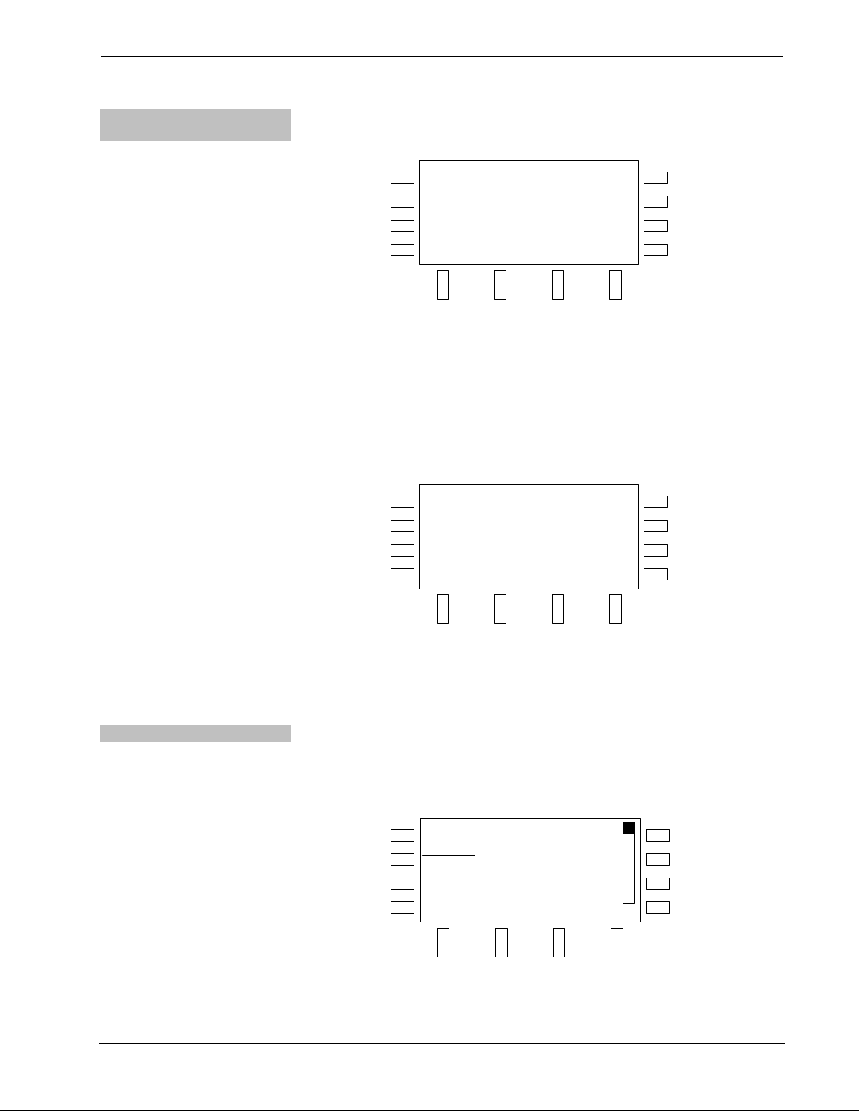
Entertainment System Crestron Adagio™ AES
Play iPod Tracks with the
AES
Use the AES front panel to control playback of tracks on the iPod.
iPod Playback Controls
SOURCE
ROOM
HOUSE
MENU
B
MY IPOD
Roy Orbison
Oh, Pretty Woman
FHE
Music
1/15
BKLT
SCHED
DISPLAY
MORE
• Press the soft button labeled F to return to the beginning of the current
track or skip to the previous track. If the iPod is paused, press the soft
button labeled h to resume playback. If the iPod is currently playing, press
the soft button labeled B to pause playback. Press the soft button labeled E
to skip to the next track. Press the soft button labeled Music to open the
iPod track menu (for details, refer to “Select Tracks with the AES” below).
Press the DISPLAY button to toggle between the artist name and the album
name. Press the MORE button to view more playback options.
iPod Playback Controls, Page 2
SOURCE
ROOM
B
Roy Orbison
Oh, Pretty Woman
1/15
BKLT
SCHED
Select Tracks with the AES
HOUSE
MENU
MY IPOD
Shuffle Repeat
DISPLAY
MORE
• Press the soft button labeled Shuffle to change the Shuffle mode of the
iPod. Press the soft button labeled Repeat to change the repeat mode of the
iPod. Press the MORE button to return to the main playback controls.
The AES front panel can be used to select a specific playlist, artist, album, or track
on an iPod.
• Press the soft button labeled Music to open the iPod Music menu.
Music Menu
SOURCE
ROOM
HOUSE
MENU
Music
Playlists
Artists
Albums
Menu Bottom
BKLT
SCHED
DISPLAY
MORE
52 • Entertainment System: Adagio AES Operations Guide – DOC. 6456B
Page 57

Crestron Adagio™ AES Entertainment System
• Turn the selection knob to highlight an item (Playlists, Artists, Albums,
etc.) and press the ENTER button. The scroll bar indicates the position of
the cursor on the displayed list. To jump to the first item in the list, turn the
selection knob counterclockwise and press the soft button labeled Top. To
jump to the last item in the list, turn the selection knob clockwise and press
the soft button labeled Bottom. If a track name is selected, pressing the
ENTER button will begin playback.
Playlist Items
Find the AAS Controls
SOURCE
ROOM
HOUSE
MENU
My Favorites
As Tears Go By
Baba O’Riley
Bad
Back Bottom
BKLT
SCHED
DISPLAY
MORE
• When viewing a list of tracks, press the ENTER button to play the selected
track. To jump to the first item in the list, turn the selection knob
counterclockwise and press the soft button labeled Top. To jump to the last
item in the list, turn the selection knob clockwise and press the soft button
labeled Bottom. To return to the previous topic (playlist, album, etc.) press
the soft button labeled Back.
Controlling an Adagio Audio Server (AAS)
An AAS can be controlled from the AES front panel.
The following assumes that the AAS has been installed and connected as described
in the AAS guide.
• Place the AES in the Source mode (refer to “Select a Source” on page 37).
• Turn the selection knob to an AAS source (source 7 for an AAS-1, sources
7 or 8 for an AAS-2, or sources 7, 8, 9, or 10 for an AAS-4 if using out-ofthe-box functionality). The playback status, current track, and artist playing
on the AAS source will be displayed.
AAS Source
SOURCE
ROOM
HOUSE
MENU
A
Control
Server 1
Aerosmith
Angel
BKLT
SCHED
DISPLAY
MORE
• Press the soft button labeled Control to open the AAS controls which
displays the playback status, current track, song position in a playlist or
queue and operating controls.
Operations Guide – DOC. 6456B Entertainment System: Adagio AES • 53
Page 58

Entertainment System Crestron Adagio™ AES
AAS Controls
SOURCE
ROOM
HOUSE
MENU
B
Server 1
FHE
Aerosmith
Angel
1/15
Music
BKLT
SCHED
DISPLAY
MORE
⇒
Press the soft button labeled F to return to the beginning of the current
track or skip to the previous track in the queue.
⇒
If the AAS output is paused, press the soft button labeled h to resume
playback of the current track. If the AAS output is playing, press the soft
button labeled B to pause playback of the current track.
⇒
Press the soft button labeled E to skip to the next track in the queue.
⇒
Press the soft button labeled Music to open the AAS library and select
albums, artists, tracks, etc. to play or add to the queue. Refer to page 56 for
details.
⇒
Press the DISPLAY button to toggle between the artist name and the
album name.
⇒
Press the MORE button to view other controls.
AAS Controls (Other Controls)
Shuffle Control
SOURCE
ROOM
HOUSE
MENU
B
Server 1
Shuffle Repeat Queue
Aerosmith
Angel
1/15
BKLT
SCHED
DISPLAY
MORE
Press the soft button labeled Shuffle to access the AAS
output’s shuffle controls.
Press the soft button labeled Repeat to access the AAS
output’s repeat controls.
Press the soft button labeled Queue to view items in the queue
or save a queue as a playlist.
Press the MORE button to return to the main playback
controls.
Use the AES front panel to control the shuffle mode of an AAS output. Each
output’s shuffle mode can be controlled independently.
• Open the AAS playback controls as described on page 53, press the MORE
button, and press the soft button labeled Shuffle to open the shuffle
controls.
54 • Entertainment System: Adagio AES Operations Guide – DOC. 6456B
Page 59

Crestron Adagio™ AES Entertainment System
AAS Shuffle Controls
Repeat Control
SOURCE
ROOM
HOUSE
MENU
Shuffle Mode
Off
Selections
Tracks
BKLT
SCHED
DISPLAY
MORE
• Turn the selection knob to highlight a shuffle mode.
⇒
Off plays all queued items in sequence.
⇒
Selections will randomize all items in the play queue. Group items
such as Playlists will be played in order. However, the order of
group items will be shuffled.
⇒
Tracks will shuffle all of the tracks in the play queue.
• Press the ENTER button to select the highlighted mode.
Use the AES front panel to control the repeat mode of an AAS output. Each output’s
repeat mode can be controlled independently.
• Open the AAS playback controls as described on page 53, press the MORE
button, and press the soft button labeled Repeat to open the repeat controls.
Queue Management
AAS Repeat Controls
SOURCE
ROOM
HOUSE
MENU
Repeat Mode
Off
Track
Queue
BKLT
SCHED
DISPLAY
MORE
• Turn the selection knob to highlight a repeat mode.
⇒
Off plays all queued items once.
⇒
Track will repeat the track that is currently playing.
⇒
Queue will repeat all of the tracks in the play queue.
• Press the ENTER button to select the highlighted mode.
The AES front panel can be used to manage items in the play queue and save a queue
as a playlist on the AAS.
• Open the AAS playback controls as described on page 53, press the MORE
button, and press the soft button labeled Queue to view the play queue
controls.
Operations Guide – DOC. 6456B Entertainment System: Adagio AES • 55
Page 60

Entertainment System Crestron Adagio™ AES
Play Queue Controls
SOURCE
ROOM
HOUSE
MENU
Play Queue
1. Artist: Adam Ant
2. Track: Dream On
3. Track: Lump
Save BottomClear
BKLT
SCHED
DISPLAY
MORE
The scroll bar indicates the position of the cursor on the displayed list. To
jump to the first item in the list, turn the selection knob counterclockwise
and press the soft button labeled Top. To jump to the last item in the list,
turn the selection knob clockwise and press the soft button labeled Bottom.
• To clear an item, turn the selection knob to highlight an item (Artist, Track,
etc.) and press the ENTER button.
• To clear the play queue, press the soft button labeled Clear.
• To save the play queue as a playlist, press the soft button labeled Save and
create a name for the playlist.
Enter New Playlist Name
SOURCE
ROOM
HOUSE
MENU
Enter New Playlist Name
ABCDEFGHIJKLM
NOPQRSTUVWXYZ
EnterBack
BKLT
SCHED
DISPLAY
MORE
Browse the AAS Library with
the AES
⇒
Select a letter with the selection knob and press the ENTER
button.
⇒
To move back a space, press the soft button labeled Back.
⇒
To save the playlist name, press the soft button labeled Enter.
The AES front panel can be used to select a category (playlist, artist, album, era, etc.)
or song in the AAS library. Categories and individual tracks can either be played or
added to the play queue.
• Press the soft button labeled Music to open the Browse menu.
56 • Entertainment System: Adagio AES Operations Guide – DOC. 6456B
Page 61

Crestron Adagio™ AES Entertainment System
Browse Menu
SOURCE
ROOM
HOUSE
MENU
Browse
Genres
Artists
Albums
Bottom
BKLT
SCHED
DISPLAY
MORE
The scroll bar indicates the position of the cursor on the displayed list. To
jump to the first item in the list, turn the selection knob counterclockwise
and press the soft button labeled Top. To jump to the last item in the list,
turn the selection knob clockwise and press the soft button labeled Bottom.
• To select an item (Genre, Artists, Albums, track, etc.), turn the selection
knob to highlight the item and press the ENTER button.
For more information on the library structure, refer to the latest version of
the AAS guide.
Track List
SOURCE
ROOM
HOUSE
MENU
Tracks
(All Tracks)
8. Bette Davis Eyes
11. If This Is It
Back Bottomh Search
BKLT
SCHED
DISPLAY
MORE
Search the AAS Library with
the AES
• Press the soft button labeled H to play the current selection and replace the
current queue. If “All Tracks” or an individual track is selected, press the
ENTER button to choose between playing the current selection (thereby
replacing the queue) or adding the selected item to the current queue.
Choose Action
SOURCE
ROOM
HOUSE
MENU
Choose One
BKLT
SCHED
DISPLAY
CancelPlay Add
MORE
• Press the soft button labeled Search to search for a specific item.
NOTE: Searches are performed within a category. For example, searching
for a song title while browsing artists will not yield any results.
Operations Guide – DOC. 6456B Entertainment System: Adagio AES • 57
Page 62

Entertainment System Crestron Adagio™ AES
Search
SOURCE
ROOM
HOUSE
MENU
Select the desired letter
to jump to that point in the list.
ABCDEFGHIJKLM
NOPQRSTUVWXYZ
BKLT
SCHED
DISPLAY
EnterBack
MORE
⇒
Select a letter with the selection knob and press the ENTER
button.
⇒
To move back a space, press the soft button labeled Back.
⇒
To begin the search, press the soft button labeled Enter.
Route a Source
Rooms that are connected to the source are indicated on the room buttons.
• Select a source as described on page 37.
• Press room buttons on the AES or AAE to route the selected source to a
room.
NOTE: Volume adjustment is not available when the AES is in Source mode. When
a source is routed to a room that is not already on, the room will be turned on at the
startup volume specified on page 34.
58 • Entertainment System: Adagio AES Operations Guide – DOC. 6456B
Page 63

Crestron Adagio™ AES Entertainment System
Room Mode
Room mode is used to select and control a room that is connected to the AES. If a
room button LED is on, then the room is connected to an audio source. If a room
button LED is off, then the room is turned off.
Select a Room
Control a Room
To select a room:
• Press Room to put the AES in the Room mode. The current selected room
is displayed on the LCD.
Room Mode
SOURCE
ROOM
HOUSE
MENU
Control Source Global
Room 1
S1 AM/FM
Off
BKLT
SCHED
DISPLAY
MORE
• Turn the selection knob until the desired room is displayed on the LCD.
Alternatively, press a room button on the AES or AAE (if connected).
After a room is selected, a source can be selected, the room can be turned “off”,
room and global volume can be adjusted, or the room output can be muted.
• Select a source by pressing the soft button labeled Source and turning the
selection knob until the desired source is displayed on the LCD. Press the
ENTER button to select the source. Press the soft button labeled Control
(if available) to control the source. Press the MORE button to view options
for adjusting audio parameters (bass, treble, balance, and loudness).
• Turn on the room by pressing the soft button labeled On.
• Turn off the room by pressing the soft button labeled Off.
• Adjust the room’s volume by turning the volume knob. The volume level
will be displayed on the LCD.
• Adjust the volume in all rooms that are on by pressing the soft button
labeled Global and turning the volume knob. The global volume level will
be displayed on the LCD. Press MENU to return to the room menu.
Adjusting the global volume adjusts the volume in every room that is
currently turned on. The volumes are adjusted proportionately so the room
volume levels do not jump to the same level when the global volume
control is used.
Operations Guide – DOC. 6456B Entertainment System: Adagio AES • 59
Page 64

Entertainment System Crestron Adagio™ AES
Global Volume
Adjust the Bass
SOURCE
ROOM
HOUSE
MENU
Global Volume
Level 50%
BKLT
SCHED
DISPLAY
MORE
• Mute the room output by pressing the MUTE button (the MUTE LED will
light). Unmute the room by pressing the MUTE button again.
The bass level of each room can be adjusted independently.
• While in Room mode, press the MORE button.
• Press the soft button labeled Bass to open the Bass control.
Bass Control
SOURCE
ROOM
HOUSE
MENU
Room 3
Bass -12dB
Flat
BKLT
SCHED
DISPLAY
MORE
Adjust the Treble
• Adjust the bass level with the selection knob. Turn clockwise to raise the
bass level or counterclockwise to lower the bass level. Press the soft button
labeled Flat to set the bass level to 0dB.
NOTE: Other rooms can be adjusted by pressing a different room button.
• Press MENU to save changes and return to the previous screen.
The treble levels of each room can be adjusted independently.
• While in Room mode, press the MORE button.
• Press the soft button labeled Treble to open the Treble control.
Treble Control
SOURCE
ROOM
HOUSE
MENU
Room 3
Treble -12dB
Flat
BKLT
SCHED
DISPLAY
MORE
60 • Entertainment System: Adagio AES Operations Guide – DOC. 6456B
Page 65

Crestron Adagio™ AES Entertainment System
• Adjust the treble level with the selection knob. Turn clockwise to raise the
treble level or counterclockwise to lower the treble level. Press the soft
button labeled Flat to set the treble level to 0dB.
NOTE: Other rooms can be adjusted by pressing a different room button.
• Press the MENU button to save changes and return to the previous screen.
Adjust the Balance
The balance of each room can be adjusted independently.
• While in Room mode, press the MORE button.
• Press the soft button labeled Balance to open the Balance control.
Balance Control
SOURCE
ROOM
HOUSE
MENU
Room 3
Balance 0
Center
BKLT
SCHED
DISPLAY
MORE
• Adjust the balance with the selection knob. Turn clockwise to set the
balance to the right or counterclockwise to set the balance to the left. Press
the soft button labeled Center to center the balance.
NOTE: Other rooms can be adjusted by pressing a different room button.
• Press MENU to save changes and return to the previous screen.
Set Loudness
The loudness settings of each room can be adjusted independently.
• While in Room mode, press the MORE button.
• Press the soft button labeled Loud to open the Loudness control.
Loudness Control
SOURCE
ROOM
HOUSE
MENU
Loudness
Room 3
On
Off
BKLT
SCHED
DISPLAY
MORE
• The current setting is underlined. To turn loudness on, press the soft button
labeled On. To turn loudness off, press the soft button labeled Off.
NOTE: Other rooms can be adjusted by pressing a different room button.
Operations Guide – DOC. 6456B Entertainment System: Adagio AES • 61
Page 66

Entertainment System Crestron Adagio™ AES
• Press MENU to save changes and return to the previous screen.
Recall a Preset Group
Press any preset group button to recall a preset group. If a room is shared by two or
more preset groups, the source from the most recently selected preset group will be
routed to all of the selected groups.
Lock and Unlocking the Front Panel Controls
The front panel controls can be locked by pressing the MENU and DISPLAY
buttons simultaneously for five seconds.
The front panel controls can be unlocked by pressing the MENU and DISPLAY
buttons simultaneously for five seconds.
Turn off the System
Press STANDBY to turn off all of the rooms.
62 • Entertainment System: Adagio AES Operations Guide – DOC. 6456B
Page 67

Crestron Adagio™ AES Entertainment System
Programming Software
Refer to this section only if a custom program for the AES is to be created.
A built-in program containing the out-of-the-box functionality resides in a protected
area of the AES’ flash memory. The program cannot be erased and can be recalled at
any time by holding the software reset button during a hardware reset.
The built-in-program cannot be modified using the tools described in this section.
Have a question or comment about Crestron software?
Answers to frequently asked questions (FAQs) can be viewed in the Online Help
section of the Crestron website. To post a question or view questions you have
submitted to Crestron’s True Blue Support, log in at http://support.crestron.com.
First-time users will need to establish a user account.
Earliest Version Software Requirements for the PC
NOTE: Crestron recommends that you use the latest software to take advantage of
the most recently released features. The latest software is available from the Crestron
website.
NOTE: Crestron software and any files on the website are for authorized Crestron
dealers and Crestron Authorized Independent Programmers (CAIP) only. New users
may be required to register to obtain access to certain areas of the site (including the
FTP site).
Crestron has developed an assortment of Windows-based software tools to develop
a Cresnet system. The following are the minimum recommended software versions
for the PC:
Software
TASK REQUIRED SOFTWARE VERSION
Simplified programming with
wizards for Adagio systems
(optional but recommended)
Program the AES functions
Uploading program and firmware Crestron Toolbox 1.02.17 or later
Adagio Composer; part of Crestron
SystemBuilder™ version 3.0 (3.1.18 if using
ATC-AMFMSR or AES-SR) or later with
SystemBuilder Templates version 3.0 (3.2 if
using ATC-AMFMSR or AES-SR) or later;
Refer to software release notes or Crestron
website for other required Crestron
software packages
SIMPL Windows version 2.07.20 or later
with SIMPL+ Cross Compiler version 1.1 or
later; Also requires Crestron Database
version 18.0 or later (18.6 if using
ATC-AMFMSR or AES-SR)
(Continued on following page)
Operations Guide – DOC. 6456B Entertainment System: Adagio AES • 63
Page 68

Entertainment System Crestron Adagio™ AES
Software (Continued)
TASK REQUIRED SOFTWARE VERSION
Create custom LCD screens and
page flips for custom programs
Create labels for room and preset
group buttons
Vision Tools® Pro-e version 3.5 or later (add
AES Front Panel Patch 1.0 if using
ATC-AMFMSR or AES-SR); Requires
Crestron Database version 18.0 or later
(18.6 if using ATC-AMFMSR or AES-SR)
Crestron Engraver 2.7.0.1 or later; Requires
Crestron Database version 18.0 or later
Programming with Adagio Composer
To add additional Crestron sources, third-party sources, and interfaces use Adagio
Composer. Adagio Composer is part of the Crestron SystemBuilder application
which can be downloaded from the Crestron website.
Adagio Composer provides a quick method of configuring a custom audio
distribution system without prior programming knowledge. For additional details,
download Adagio Composer from the Crestron website and examine the extensive
help file.
To create more advanced systems that include non-audio distribution devices such as
lighting and HVAC, use Crestron SystemBuilder or SIMPL Windows.
Programming with Crestron SystemBuilder
The easiest method of programming a Crestron system. For additional details,
download SystemBuilder from the Crestron website and examine the extensive help
file.
Any program created for the AES with SystemBuilder will include the out-of-thebox functionality in addition to any additional programming created with
SystemBuilder.
For lower level control and additional programming flexibility, use SIMPL
Windows.
Programming with SIMPL Windows
NOTE: While SIMPL Windows can be used to program the AES, it is
recommended to use Adagio Composer or SystemBuilder for configuring a system.
SIMPL Windows is Crestron’s premier software for programming Crestron control
systems. It is organized into two separate, but equally important “Managers”.
Any SIMPL Windows program written for an AES will contain all of the AES’ outof-the-box functions in a protected area of the program. The parts of the program that
contain the out-of-the-box functions are locked and cannot be changed or deleted.
When a program is compiled, the custom program plus the out-of-the-box program’s
logic, default front panel operation, and control device (APAD or keypad) logic are
loaded.
NOTE: When programming an AES in SIMPL Windows, always begin with the
example program and modify as required. To find example programs, refer to
“Example Program” on page 67. Also visit Crestron’s True Blue Support on the web
for more programming tips.
64 • Entertainment System: Adagio AES Operations Guide – DOC. 6456B
Page 69

Crestron Adagio™ AES Entertainment System
Configuration Manager
Programming Manager
Configuration Manager is the view where programmers “build” a Crestron control
system by selecting hardware from the Device Library.
• To incorporate the AES into the system, drag the AES from the Control
Systems folder of the Device Library and drop it in the System Views.
Locating the AES in the Device Library
Programming Manager is the view where programmers "program" a Crestron control
system by assigning signals to symbols.
Signals that are part of the AES’ out-of-the-box functionality are locked and cannot
be modified or deleted. Locked signals are grayed out in the AES’ SIMPL Windows
symbols. To prevent corruption of the out-of-the-box functionality, locked signals
names should not be copied or driven to other destinations in the SIMPL Windows
program.
NOTE: If using SIMPL Windows version 2.08.19 or later, signals that are part of
the out-of-the-box functionality may be hidden from view. To view hidden signals in
a program containing out-of-the-box functionality, select Display Out Of The Box
Functionality (OOTBF) Programming in the “SIMPL Windows Preferences”
window (Options | Preferences…).
The symbol can be viewed by double clicking on the icon or dragging it into Detail
View. A description for each signal in the symbol is described in the SIMPL
Windows help file (F1).
Programming with VisionTools Pro-e
LCD screens and page flips can be created in VisionTools Pro-e (VT Pro-e) for
custom programs using the HOUSE button on the AES front panel. For more
information, refer to the VT Pro-e help file (F1).
Switching Programs
If a custom program is loaded into the AES, the AES will run the custom program
when it boots up. To switch to the out-of-the-box program:
1. Press and release HW-R.
2. Press and hold SW-R until "Bypassing Custom Program, Running OOTBF"
is displayed on the LCD.
3. To return to the custom program simply press HW-R or cycle power.
Operations Guide – DOC. 6456B Entertainment System: Adagio AES • 65
Page 70

Entertainment System Crestron Adagio™ AES
Saving Settings
Settings such as tone/volume levels (out-of-the-box and custom programs) and
input/output names (out-of-the-box programs) are stored in an xml and text file that
can be recalled should a AES program need to be updated.
To save settings for later use, use the Crestron Toolbox File Manager utility to
retrieve the *.xml (where * can be “ootbf” for settings made when running the outof-the-box functionality program or “custom” for settings made when running a
custom program) and System Configuration.txt files from the NVRAM Disk
directory. After the new out-of-the-box functionality program or custom program has
been loaded, use Windows Explorer and Crestron Toolbox’ File Manager utility to
place the appropriate *.xml and System Configuration.txt files in the NVRAM Disk
directory and reboot the processor. For instructions on using Crestron Toolbox’ File
Manager utility, refer to the Crestron Toolbox help file.
NOTE: If switching to a different type of program (i.e. from out-of-the-box
functionality to custom or vice-versa), the retrieved xml file can be renamed
(ootbf.xml becomes custom.xml and custom.xml becomes ootbf.xml). The running
program will import any relevant settings. Verify that all of the required settings are
correct.
Example Program
An example program for the AES is available from the Crestron website
(http://www.crestron.com/exampleprograms).
66 • Entertainment System: Adagio AES Operations Guide – DOC. 6456B
Page 71

Crestron Adagio™ AES Entertainment System
Uploading and Upgrading
Crestron recommends using the latest programming software and that each device
contains the latest firmware to take advantage of the most recently released features.
However, before attempting to upload or upgrade it is necessary to establish
communication. Once communication has been established, files (for example,
programs, or firmware) can be transferred to the control system (and/or device).
Finally, program checks can be performed (such as changing the device ID or
creating an IP table) to ensure proper functioning.
While the next section provides an overview for communication, refer to
“Establishing Communications with the Control System” in the Crestron 2-Series
Control Systems Reference Guide (Doc. 6256) for connection details. If
communications cannot be established, refer to “Troubleshooting Communications”
in the same guide.
Establishing Communication
Use Crestron Toolbox for communicating with the AES; refer to the Crestron
Toolbox help file for details. There are three methods of communication.
Direct Serial Communication
USB Communication
NOTE: Serial Communication or USB communication (see below) must be used
for initial setup of Ethernet parameters when the out-of-the-box functionality is not
used.
Direct Serial Communication
PC RUNNING
CRESTRON TOOLBOX
SERIAL VIA CRESTRON
CABLE STCP-502
OR EQUIVALENT
AES
• The COMPUTER port on the AES connects to the serial port on the PC via
the included serial cable (Crestron STCP-502PC or equivalent).
• Use the Address Book in Crestron Toolbox to create an entry using the
expected serial communication protocol (RS232, auto-detect baud rate, no
parity, 8 data bits, 1 stop bit, XON/XOFF disabled, RTS/CTS enabled).
• Display the AES’ “System Info” window (click the
icon);
communications are confirmed when the device information is displayed.
NOTE: USB Communication or Serial communication (shown above) must be used
for initial setup of Ethernet parameters when the out-of-the-box functionality is not
used.
USB Communication
PC RUNNING
CRESTRON TOOLBOX
Operations Guide – DOC. 6456B Entertainment System: Adagio AES • 67
USB COMMUNICATIONS
VIA USB CABLE
AES
Page 72

Entertainment System Crestron Adagio™ AES
• The USB port on the AES connects to the USB port on the PC via the
included USB cable.
• Use the Address Book in Crestron Toolbox to create an entry using the
expected communication protocol (USB). When multiple USB devices are
connected, identify the AES by entering “AES” in the Model textbox, the
unit’s serial number in the Serial textbox or the unit’s hostname in the
Hostname textbox. The hostname can be found in the “System Info”
window in the section marked Ethernet however, communications must be
established in order to see this information in the “System Info” window.
TCP/IP Communication
• Display the AES’ “System Info” window (click the
icon);
communications are confirmed when the device information is displayed.
NOTE: A connection to an Ethernet network is required for operation with a
CEN-IDOC, AAS, or any other TCP/IP enabled device.
Ethernet Communication
PC RUNNING
CRESTRON TOOLBOX
ETHERNET
AES
• Establish serial or USB communication between AES and PC.
• Enter the IP address, IP mask, and default router of the AES via Crestron
Toolbox (Functions | Ethernet Addressing); otherwise enable DHCP.
NOTE: When taken out of the box, the AES is configured for DHCP
operation. If a DHCP server is available and the AES is connected to the
network, the IP address can be obtained from the About screen as described
on page 32.
• Confirm Ethernet connections between AES and PC. If connecting through
a hub, use CAT5 straight through cables with 8-pin RJ-45 connectors.
Alternatively, Use a CAT5 crossover cable to connect the two LAN ports
directly, without using a hub.
• Use the Address Book in Crestron Toolbox to create an entry for the
AES with the AES’ TCP/IP communication parameters.
• Display the “System Info” window (click the
icon) and select the
AES entry. Communications are confirmed when the device information is
displayed.
Programs and Firmware
Program or firmware files may be distributed from programmers to installers or from
Crestron to dealers. Firmware upgrades are available from the Crestron website as
new features are developed after product releases. One has the option to upload
programs via the programming software or to upload and upgrade via the Crestron
Toolbox. For details on uploading and upgrading, refer to the SIMPL Windows help
file or the Crestron Toolbox help file.
68 • Entertainment System: Adagio AES Operations Guide – DOC. 6456B
Page 73

Crestron Adagio™ AES Entertainment System
SIMPL Windows
Firmware
If a SIMPL Windows program is provided, it can be uploaded to the control system
using SIMPL Windows or Crestron Toolbox.
Check the Crestron website to find the latest firmware. (New users may be required
to register to obtain access to certain areas of the site, including the FTP site.)
Upgrade AES firmware via Crestron Toolbox.
• Establish serial, USB, or TCP/IP communications with the AES and display
the “System Info” window.
• Select Functions | Firmware… to upgrade the AES firmware.
For details on uploading and upgrading, refer to the SIMPL Windows help file or the
Crestron Toolbox help file.
Operations Guide – DOC. 6456B Entertainment System: Adagio AES • 69
Page 74

Entertainment System Crestron Adagio™ AES
Problem Solving
Troubleshooting
The following table provides corrective action for possible trouble situations. If
further assistance is required, please contact a Crestron customer service
representative.
AES Troubleshooting
TROUBLE POSSIBLE CAUSE(S) CORRECTIVE ACTION
AES does not
function.
C2N-DBF12 or
APAD does not
function.
AES only allows
six rooms
(maximum) when
using the out-ofthe-box
functionality.
Buttons on AAE
do not light or do
anything.
Tuner cards are
not listed on the
LCD or APAD as
available sources.
CEN-IDOC or
AAS devices not
listed on the LCD
or APAD as
available sources.
AES is not receiving
power.
AES is not
communicating with
C2N-DBF12 or APAD
devices.
AAE is not properly
connected to the AES.
AAE is not registered
with AES.
AAE is not properly
connected to the AES.
AAE is not registered
with AES.
Tuner card is not
properly installed.
CEN-IDOC or AAS are
not receiving power.
CEN-IDOC or AAS are
not communicating with
AES over Ethernet.
Use the provided power cord.
Verify connection.
Verify that C2N-DBF12 and
APAD devices are properly
connected to the AES and
are identified by the AES as
described on page 29.
Verify that the AAE is
properly connected to the
AES.
Open Installer Tools and
select “Identify Keypads”.
Identify all keypads in the
system.
Use Crestron Toolbox to
manually set the AAEs Net ID
to 31.
Verify that the AAE is
properly connected to the
AES.
Open Installer Tools and
select “Identify Keypads”.
Identify all keypads in the
system.
Use Crestron Toolbox to
manually set AAE Net ID to
31.
Refer to the tuner card’s
guide for installation
instructions.
Verify that each device is
receiving power.
Verify each device’s TCP/IP
settings.
(Continued on following page)
70 • Entertainment System: Adagio AES Operations Guide – DOC. 6456B
Page 75
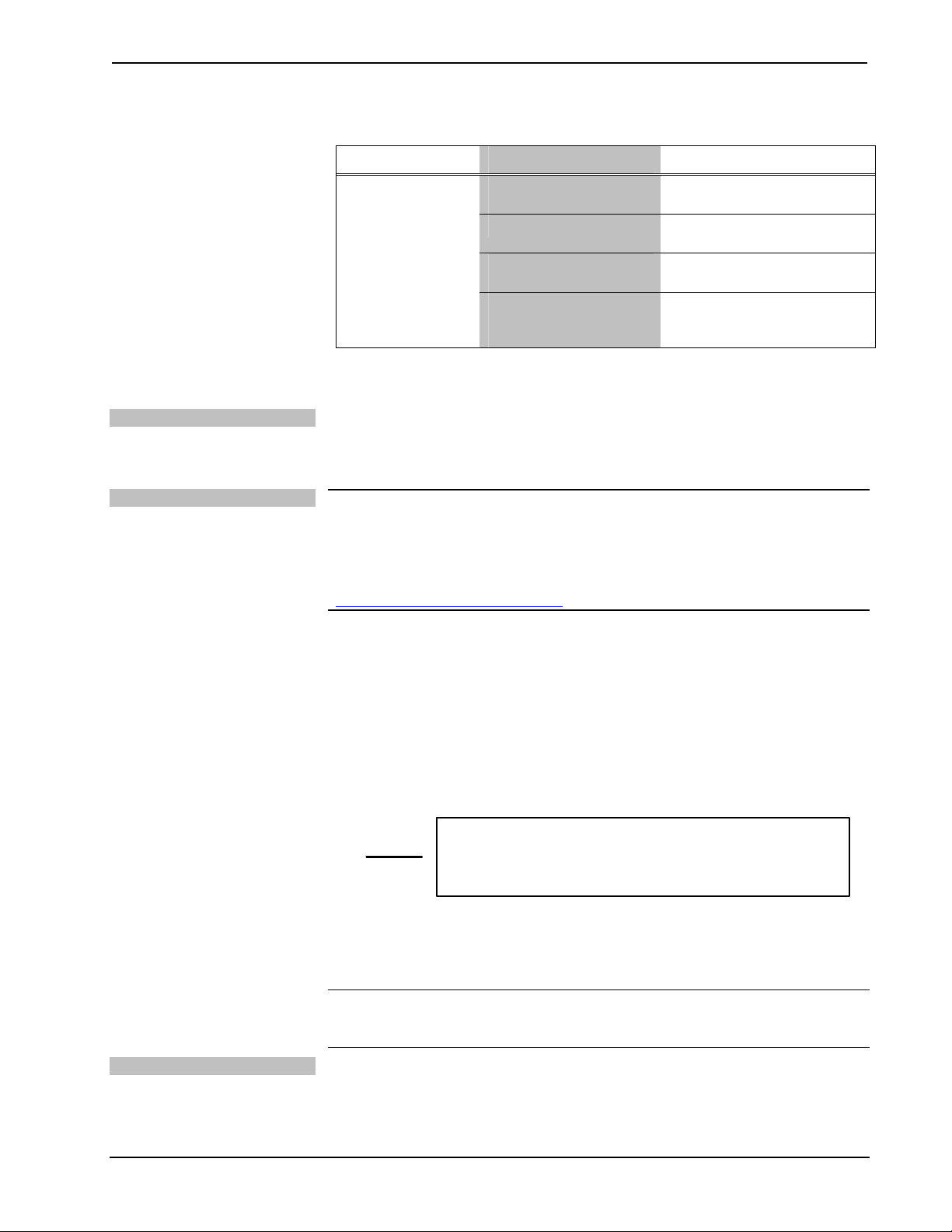
Crestron Adagio™ AES Entertainment System
AES Troubleshooting (Continued)
TROUBLE POSSIBLE CAUSE(S) CORRECTIVE ACTION
Use the Right Wire
Calculate Power
Sound is not
heard.
Room is muted or
turned off.
Volume is turned down.
Speakers are not
properly connected.
Source is not
selected/properly
connected.
Turn off mute function or
route a source to the room.
Raise volume to an audible
level.
Verify speaker connections.
Verify that source is selected
and properly connected.
Check Network Wiring
In order to ensure optimum performance over the full range of your installation
topology, Crestron Certified Wire, and only Crestron Certified Wire, may be used.
Failure to do so may incur additional charges if support is required to identify
performance deficiencies because of using improper wire.
CAUTION: Use only Crestron power supplies for Crestron equipment. Failure to do
so could cause equipment damage or void the Crestron warranty.
CAUTION: Provide sufficient power to the system. Insufficient power can lead to
unpredictable results or damage to the equipment. Please use the Crestron Power
Calculator to help calculate how much power is needed for the system
(http://www.crestron.com/calculators
When calculating the length of wire for a particular Cresnet run, the wire gauge and
the Cresnet power usage of each network unit to be connected must be taken into
consideration. Use Crestron Certified Wire only. If Cresnet units are to be daisychained on the run, the Cresnet power usage of each network unit to be daisy-chained
must be added together to determine the Cresnet power usage of the entire chain. If
the unit is home-run from a Crestron system power supply network port, the Cresnet
power usage of that unit is the Cresnet power usage of the entire run. The wire gauge
and the Cresnet power usage of the run should be used in the following equation to
calculate the cable length value on the equation’s left side.
Cable Length Equation
).
L = Length of run (or chain) in feet
R = 6 Ohms (Crestron Certified Wire: 18 AWG (0.75 MM ))
or 1.6 Ohms (Cresnet HP: 12 AWG (4 MM ))
P = Cresnet power usage of entire run (or chain)
2
2
L <
40,000
Where:
R x P
Make sure the cable length value is less than the value calculated on the right side of
the equation. For example, a Cresnet run using 18 AWG Crestron Certified Wire and
drawing 20 watts should not have a length of run more than 333 feet. If Cresnet HP is
used for the same run, its length could extend to 1250 feet.
NOTE: All Crestron certified Cresnet wiring must consist of two twisted pairs. One
twisted pair is the +24V conductor and the GND conductor and the other twisted pair
is the Y conductor and the Z conductor.
Strip and Tin Wire
When daisy-chaining Cresnet units, strip the ends of the wires carefully to avoid
nicking the conductors. Twist together the ends of the wires that share a pin on the
network connector, and tin the twisted connection. Apply solder only to the ends of
the twisted wires. Avoid tinning too far up the wires or the end becomes brittle. Insert
Operations Guide – DOC. 6456B Entertainment System: Adagio AES • 71
Page 76

Entertainment System Crestron Adagio™ AES
the tinned connection into the Cresnet connector and tighten the retaining screw.
Repeat the procedure for the other three conductors.
Add Hubs
For larger networks (i.e., greater than 28 network devices), it may become necessary
to add a Cresnet Hub/Repeater (CNXHUB) to maintain signal quality throughout the
network. Also, for networks with lengthy cable runs, it may be necessary to add a
Hub/Repeater after only 20 devices.
Reference Documents
The latest version of all documents mentioned within the guide can be obtained from
the Crestron website (http://www.crestron.com/manuals). This link will provide a list
of product manuals arranged in alphabetical order by model number.
List of Related Reference Documents
DOCUMENT TITLE
2-Series Control Systems Reference Guide
AAE Audio Expander
AAS Audio Server
APAD Wall Mount LCD Controller
ATC-AMFM2 Dual AM/FM Tuner Card
ATC-AMFMXM AM/FM/XM Tuner Card
ATC-AMFMSR AM/FM/SIRIUS Tuner Card
C2N-DBF12 Decorator Wall Panels
CEN-IDOC Interface for Apple iPod®
Crestron e-Control Reference Guide
User Interface Device Out-Of-The-Box Functionality Guide
Further Inquiries
If you cannot locate specific information or have questions after reviewing this
guide, please take advantage of Crestron's award winning customer service team by
calling the Crestron corporate headquarters at 1-888-CRESTRON [1-888-273-7876].
For assistance in your local time zone, refer to the Crestron website
(http://www.crestron.com/
You can also log onto the online help section of the Crestron website to ask
questions about Crestron products. First-time users will need to establish a user
account to fully benefit from all available features.
) for a listing of Crestron worldwide offices.
Future Updates
As Crestron improves functions, adds new features, and extends the capabilities of
the AES, additional information may be made available as manual updates. These
updates are solely electronic and serve as intermediary supplements prior to the
release of a complete technical documentation revision.
Check the Crestron website periodically for manual update availability and its
relevance. Updates are identified as an “Addendum” in the Download column.
72 • Entertainment System: Adagio AES Operations Guide – DOC. 6456B
Page 77

Crestron Adagio™ AES Entertainment System
Software License Agreement
This License Agreement (“Agreement”) is a legal contract between you (either an individual or a single business entity) and
Crestron Electronics, Inc. (“Crestron”) for software referenced in this guide, which includes computer software and as applicable,
associated media, printed materials and “online” or electronic documentation (the “Software”).
BY INSTALLING, COPYING OR OTHERWISE USING THE SOFTWARE, YOU REPRESENT THAT YOU ARE AN
AUTHORIZED DEALER OF CRESTRON PRODUCTS OR A CRESTRON AUTHORIZED INDEPENDENT PROGRAMMER
AND YOU AGREE TO BE BOUND BY THE TERMS OF THIS AGREEMENT. IF YOU DO NOT AGREE TO THE TERMS OF
THIS AGREEMENT, DO NOT INSTALL OR USE THE SOFTWARE.
IF YOU HAVE PAID A FEE FOR THIS LICENSE AND DO NOT ACCEPT THE TERMS OF THIS AGREEMENT,
CRESTRON WILL REFUND THE FEE TO YOU PROVIDED YOU (1) CLICK THE DO NOT ACCEPT BUTTON, (2) DO NOT
INSTALL THE SOFTWARE AND (3) RETURN ALL SOFTWARE, MEDIA AND OTHER DOCUMENTATION AND
MATERIALS PROVIDED WITH THE SOFTWARE TO CRESTRON AT: CRESTRON ELECTRONICS, INC., 15 VOLVO
DRIVE, ROCKLEIGH, NEW JERSEY 07647, WITHIN 30 DAYS OF PAYMENT.
LICENSE TERMS
Crestron hereby grants You and You accept a nonexclusive, nontransferable license to use the Software (a) in machine
readable object code together with the related explanatory written materials provided by Creston (b) on a central processing unit
(“CPU”) owned or leased or otherwise controlled exclusively by You and (c) only as authorized in this Agreement and the related
explanatory files and written materials provided by Crestron.
If this software requires payment for a license, you may make one backup copy of the Software, provided Your backup copy
is not installed or used on any CPU. You may not transfer the rights of this Agreement to a backup copy unless the installed copy of
the Software is destroyed or otherwise inoperable and You transfer all rights in the Software.
You may not transfer the license granted pursuant to this Agreement or assign this Agreement without the express written
consent of Crestron.
If this software requires payment for a license, the total number of CPU’s on which all versions of the Software are installed
may not exceed one per license fee (1) and no concurrent, server or network use of the Software (including any permitted back-up
copies) is permitted, including but not limited to using the Software (a) either directly or through commands, data or instructions from
or to another computer (b) for local, campus or wide area network, internet or web hosting services or (c) pursuant to any rental,
sharing or “service bureau” arrangement.
The Software is designed as a software development and customization tool. As such Crestron cannot and does not
guarantee any results of use of the Software or that the Software will operate error free and You acknowledge that any development
that You perform using the Software or Host Application is done entirely at Your own risk.
The Software is licensed and not sold. Crestron retains ownership of the Software and all copies of the Software and
reserves all rights not expressly granted in writing.
OTHER LIMITATIONS
You must be an Authorized Dealer of Crestron products or a Crestron Authorized Independent Programmer to install or use
the Software. If Your status as a Crestron Authorized Dealer or Crestron Authorized Independent Programmer is terminated, Your
license is also terminated.
You may not rent, lease, lend, sublicense, distribute or otherwise transfer or assign any interest in or to the Software.
You may not reverse engineer, decompile or disassemble the Software.
You agree that the Software will not be shipped, transferred or exported into any country or used in any manner prohibited
by the United States Export Administration Act or any other export laws, restrictions or regulations (“Export Laws”). By downloading
or installing the Software You (a) are certifying that You are not a national of Cuba, Iran, Iraq, Libya, North Korea, Sudan, Syria or
any country to which the United States embargoes goods (b) are certifying that You are not otherwise prohibited from receiving the
Software and (c) You agree to comply with the Export Laws.
If any part of this Agreement is found void and unenforceable, it will not affect the validity of the balance of the Agreement,
which shall remain valid and enforceable according to its terms. This Agreement may only be modified by a writing signed by an
authorized officer of Crestron. Updates may be licensed to You by Crestron with additional or different terms. This is the entire
agreement between Crestron and You relating to the Software and it supersedes any prior representations, discussions, undertakings,
communications or advertising relating to the Software. The failure of either party to enforce any right or take any action in the event
of a breach hereunder shall constitute a waiver unless expressly acknowledged and set forth in writing by the party alleged to have
provided such waiver.
Operations Guide – DOC. 6456B Entertainment System: Adagio AES • 73
Page 78

Entertainment System Crestron Adagio™ AES
If You are a business or organization, You agree that upon request from Crestron or its authorized agent, You will within
thirty (30) days fully document and certify that use of any and all Software at the time of the request is in conformity with Your valid
licenses from Crestron of its authorized agent.
Without prejudice to any other rights, Crestron may terminate this Agreement immediately upon notice if you fail to comply
with the terms and conditions of this Agreement. In such event, you must destroy all copies of the Software and all of its component
parts.
PROPRIETARY RIGHTS
Copyright. All title and copyrights in and to the Software (including, without limitation, any images, photographs,
animations, video, audio, music, text and “applets” incorporated into the Software), the accompanying media and printed materials
and any copies of the Software are owned by Crestron or its suppliers. The Software is protected by copyright laws and international
treaty provisions. Therefore, you must treat the Software like any other copyrighted material, subject to the provisions of this
Agreement.
Submissions. Should you decide to transmit to Crestron’s website by any means or by any media any materials or other
information (including, without limitation, ideas, concepts or techniques for new or improved services and products), whether as
information, feedback, data, questions, comments, suggestions or the like, you agree such submissions are unrestricted and shall be
deemed non-confidential and you automatically grant Crestron and its assigns a non-exclusive, royalty-free, worldwide, perpetual,
irrevocable license, with the right to sublicense, to use, copy, transmit, distribute, create derivative works of, display and perform the
same.
Trademarks. CRESTRON and the Swirl Logo are registered trademarks of Crestron Electronics, Inc. You shall not remove
or conceal any trademark or proprietary notice of Crestron from the Software including any back-up copy.
GOVERNING LAW
This Agreement shall be governed by the laws of the State of New Jersey, without regard to conflicts of laws principles.
Any disputes between the parties to the Agreement shall be brought in the state courts in Bergen County, New Jersey or the federal
courts located in the District of New Jersey. The United Nations Convention on Contracts for the International Sale of Goods shall not
apply to this Agreement.
CRESTRON LIMITED WARRANTY
CRESTRON warrants that: (a) the Software will perform substantially in accordance with the published specifications for a
period of ninety (90) days from the date of receipt and (b) that any hardware accompanying the Software will be subject to its own
limited warranty as stated in its accompanying written material. Crestron shall, at its option, repair or replace or refund the license fee
for any Software found defective by Crestron if notified by you within the warranty period. The foregoing remedy shall be your
exclusive remedy for any claim or loss arising from the Software.
CRESTRON shall not be liable to honor warranty terms if the product has been used in any application other than that for
which it was intended or if it as been subjected to misuse, accidental damage, modification or improper installation procedures.
Furthermore, this warranty does not cover any product that has had the serial number or license code altered, defaced, improperly
obtained or removed.
Notwithstanding any agreement to maintain or correct errors or defects, Crestron shall have no obligation to service or
correct any error or defect that is not reproducible by Crestron or is deemed in Crestron’s reasonable discretion to have resulted from
(1) accident; unusual stress; neglect; misuse; failure of electric power, operation of the Software with other media not meeting or not
maintained in accordance with the manufacturer’s specifications or causes other than ordinary use; (2) improper installation by anyone
other than Crestron or its authorized agents of the Software that deviates from any operating procedures established by Crestron in the
material and files provided to You by Crestron or its authorized agent; (3) use of the Software on unauthorized hardware or (4)
modification of, alteration of or additions to the Software undertaken by persons other than Crestron or Crestron’s authorized agents.
ANY LIABILITY OF CRESTRON FOR A DEFECTIVE COPY OF THE SOFTWARE WILL BE LIMITED
EXCLUSIVELY TO REPAIR OR REPLACEMENT OF YOUR COPY OF THE SOFTWARE WITH ANOTHER COPY OR
REFUND OF THE INITIAL LICENSE FEE CRESTRON RECEIVED FROM YOU FOR THE DEFECTIVE COPY OF THE
PRODUCT. THIS WARRANTY SHALL BE THE SOLE AND EXCLUSIVE REMEDY TO YOU. IN NO EVENT SHALL
CRESTRON BE LIABLE FOR INCIDENTAL, CONSEQUENTIAL, SPECIAL OR PUNITIVE DAMAGES OF ANY KIND
(PROPERTY OR ECONOMIC DAMAGES INCLUSIVE), EVEN IF A CRESTRON REPRESENTATIVE HAS BEEN ADVISED
OF THE POSSIBILITY OF SUCH DAMAGES OR OF ANY CLAIM BY ANY THIRD PARTY. CRESTRON MAKES NO
WARRANTIES, EXPRESS OR IMPLIED, AS TO TITLE OR INFRINGEMENT OF THIRD-PARTY RIGHTS,
MERCHANTABILITY OR FITNESS FOR ANY PARTICULAR PURPOSE, OR ANY OTHER WARRANTIES, NOR
AUTHORIZES ANY OTHER PARTY TO OFFER ANY WARRANTIES, INCLUDING WARRANTIES OF
MERCHANTABILITY FOR THIS PRODUCT. THIS WARRANTY STATEMENT SUPERSEDES ALL PREVIOUS
WARRANTIES.
74 • Entertainment System: Adagio AES Operations Guide – DOC. 6456B
Page 79

Crestron Adagio™ AES Entertainment System
Return and Warranty Policies
Merchandise Returns / Repair Service
1. No merchandise may be returned for credit, exchange, or service without prior authorization
from CRESTRON. To obtain warranty service for CRESTRON products, contact an
authorized CRESTRON dealer. Only authorized CRESTRON dealers may contact the factory
and request an RMA (Return Merchandise Authorization) number. Enclose a note specifying
the nature of the problem, name and phone number of contact person, RMA number, and
return address.
2. Products may be returned for credit, exchange, or service with a CRESTRON Return
Merchandise Authorization (RMA) number. Authorized returns must be shipped freight
prepaid to CRESTRON, 6 Volvo Drive, Rockleigh, N.J. or its authorized subsidiaries, with
RMA number clearly marked on the outside of all cartons. Shipments arriving freight collect
or without an RMA number shall be subject to refusal. CRESTRON reserves the right in its
sole and absolute discretion to charge a 15% restocking fee, plus shipping costs, on any
products returned with an RMA.
3. Return freight charges following repair of items under warranty shall be paid by CRESTRON,
shipping by standard ground carrier. In the event repairs are found to be non-warranty, return
freight costs shall be paid by the purchaser.
CRESTRON Limited Warranty
CRESTRON ELECTRONICS, Inc. warrants its products to be free from manufacturing defects in materials
and workmanship under normal use for a period of three (3) years from the date of purchase from
CRESTRON, with the following exceptions: disk drives and any other moving or rotating mechanical
parts, pan/tilt heads and power supplies are covered for a period of one (1) year; touchscreen display and
overlay components are covered for 90 days; batteries and incandescent lamps are not covered.
This warranty extends to products purchased directly from CRESTRON or an authorized CRESTRON
dealer. Purchasers should inquire of the dealer regarding the nature and extent of the dealer's warranty, if
any.
CRESTRON shall not be liable to honor the terms of this warranty if the product has been used in any
application other than that for which it was intended, or if it has been subjected to misuse, accidental
damage, modification, or improper installation procedures. Furthermore, this warranty does not cover any
product that has had the serial number altered, defaced, or removed.
This warranty shall be the sole and exclusive remedy to the original purchaser. In no event shall
CRESTRON be liable for incidental or consequential damages of any kind (property or economic damages
inclusive) arising from the sale or use of this equipment. CRESTRON is not liable for any claim made by a
third party or made by the purchaser for a third party.
CRESTRON shall, at its option, repair or replace any product found defective, without charge for parts or
labor. Repaired or replaced equipment and parts supplied under this warranty shall be covered only by the
unexpired portion of the warranty.
Except as expressly set forth in this warranty, CRESTRON makes no other warranties, expressed or
implied, nor authorizes any other party to offer any warranty, including any implied warranties of
merchantability or fitness for a particular purpose. Any implied warranties that may be imposed by law are
limited to the terms of this limited warranty. This warranty statement supersedes all previous warranties.
Trademark Information
All brand names, product names, and trademarks are the sole property of their respective owners. Windows is a registered trademark
of Microsoft Corporation. Windows95/98/Me/XP and WindowsNT/2000 are trademarks of Microsoft Corporation. The XM name and
XM Ready are registered trademarks of XM Satellite Radio Inc. “SIRIUS” and the SIRIUS dog logo are registered trademarks of
SIRIUS Satellite Radio Inc. iPod is a trademark of Apple Computer, Inc., registered in the U.S. and other countries.
Operations Guide – DOC. 6456B Entertainment System: Adagio AES • 75
Page 80

Crestron Electronics, Inc. Operations Guide – DOC. 6456B
15 Volvo Drive Rockleigh, NJ 07647 (2014564)
Tel: 888.CRESTRON 02.07
Fax: 201.767.7576 Specifications subject to
www.crestron.com change without notice.
 Loading...