

Page 1
Xboard 1
Page 2

Owner’s Manual
© 2006 E-MU Systems
All Rights Reserved
E-MU World Headquarters
E-MU Systems
1500 Green Hills Road
Scotts Valley, CA 95066
USA
Asia Pacific Africa, Middle East
Creative Technology Ltd
31 International Business Park
Creative Resource, Singapore 609921
SINGAPORE
2E-MU Systems
Europe
Creative Labs (Ireland) Ltd
Ballycoolin Business Park
Blanchardstown, Dublin 15
IRELAND
Japan
Creative Media K. K.
Kanda Eight Bldg., 3F
4-6-7 Soto-Kanda
Chiyoda-ku, Tokyo 101-0021
JAPAN
Page 3

Table of Contents
Introduction .................................................................7
Requirements .................... ..................... ....................... ..................... ................. 8
On a PC: ..................................................................................................................8
On a Mac: ................................................................................................................ 8
Hardware Installation ........................................................................................ 8
Connecting the Xboard to your Computer ....................................................... 9
USB Connection ..................................................................................................... 9
MIDI Connection .... ........................................ ....................................................... 9
MIDI Interface .......................................................................................................10
Software Installation ........................................................................................ 11
Macintosh OS X .................... ................................................................................ 11
Windows 2000 ......................................................................................................11
Windows XP ..........................................................................................................12
Uninstalling all Audio Drivers and Applications ..............................................12
Note About Windows Logo Testing ....................................................................12
Troubleshooting ................... .............................................. .............................. 13
Lost Communication ..... ............................................ .......................................... 13
Wrong Driver in Windows XP or Windows 2000 ............................................. 13
Main Panel Controls .................................................... 17
Controller Knobs ........................................................20
Normal mode ....................................... ....................................... ..........................20
16 Channel Controller mode ................................. ............................................ . 20
3D MIDI and NRPN mode ................................. .. .......................................... .....20
Xboard 3
Page 4

Xboard 61 Panel Controls ........................................... 21
Using the Numeric Keypad ..................................................................................22
Back Panel Description ............................................... 23
Powering the Xboard ................................................. 24
Inserting Batteries into the Xboard .....................................................................24
Basic Operations ........................................................ 25
Entering Data ......................................................... ........................................ .. . 25
Selecting and Storing Patches .................................................... ......................25
Changing the MIDI Channel ............................................................................26
Transposing the Keyboard ...............................................................................27
Changing Controller CC Channel Numbers ...................................................27
16 Channel Control Mode ...............................................................................27
Working With Zones ........................................... .......................................... ...28
Note Latch Mode ...... .........................................................................................29
Latch Mode, Zones Disabled ........... ....................................................................29
Latch Mode, Zones Enabled ............................. ............................................ .......30
Snap Shot ..................................................... .....................................................30
Bypass Mode .....................................................................................................31
Editing Patch and Device Settings ...................................................................31
Scrolling Text Display ....... ............................................................................... .....32
Edit Parameters ................................................................................ .................33
PGM Send on Recall .......................................... .. .......................................... .......33
Send Program Change ..................................... .......................................... .. .........34
Bank Sel MSB .........................................................................................................34
Bank Sel LSB ..........................................................................................................35
Program Change (PGM) Browse Mode ............................................... ...............35
CC Send On Recall ...............................................................................................36
Save CC Value in Patch ......................................... .......................................... .....36
Aftertouch On/Off ................................................................................................37
Semitone Transpose ..............................................................................................37
Velocity Curve Select ...................... ......................................................................38
16 Channel CC Number ......................................................................................38
Latch High/Low Note ...........................................................................................38
X1 and X2 Functions ............................................................................................39
4E-MU Systems
Page 5

E-MU Xboard Control ..................................................44
Definitions ............... ........................................ ........................................ .........44
Xboard Control Window .................................................................................. 45
Bank View .......................... ....................................... .............................................46
Device .................................................................................................................... 47
Basic Operation ................................................................................................ 47
Patch Editor Tab ........................................................... .................................... 4 9
MIDI Controller Knob Settings .................. .........................................................49
Keyboard Settings .................................................................................................51
Program Change per MIDI Channel ...................................................... .. ...........54
Zones Tab ........................................ .................................................................. 55
Zones Graphical Display ......................................................................................55
Zones Settings .......................................................................................................56
Menu Items .................................................... ................................................... 60
Preferences ............................................................................................................60
Loading and Saving ..............................................................................................61
Edit Menu ..............................................................................................................63
View Menu .............................................................................................................63
Device Menu ...... ................................................................................ ...................63
Help Menu .............................................................................................................63
Appendix ...................................................................64
MIDI Background .............................................................................................64
MIDI Channels & Continuous Controllers ........................................................64
MIDI Program Change Commands ............................................ ........................65
MIDI Bank Select Commands .............................. .......................................... .. ...65
Footpedal Wiring .............................. ................................................................ 65
MIDI Implementation Chart ............................................................................ 66
Index ..........................................................................71
Xboard 5
Page 6

6E-MU Systems
Page 7

Introduction
INTRODUCTION
Congratulations on your purchase of the E-MU Xboard 25, Xboard 49, or Xboard
61 USB/MIDI controller. Xboard professional USB/MIDI controllers offer
unmatched playability, real-time control and programmability in portable 25 key,
49 key, and 61 key packages. All models feature full-size velocity-sensitive keys
with aftertouch, pitch and modulation wheels, and 16 controller knobs. The
Xboard 61 additionally features 16 Patch Select/Program Change buttons, and
four Zone enable/disable buttons.
These keyboards are ideal for either studio or stage use since they can be used as
stand-alone MIDI controllers or with a USB equipped PC or Macintosh computer.
The Xboard MIDI output can even be used as a MIDI interface for your computer
when connected via USB. The Xboard is ultra-portable and can be powered via
USB, battery, or using the optional 6 VDC power supply.
Each of the 16 controller knobs can be programmed to any controller number on
any MIDI channel. The keyboard can be transposed up or down ±4 octaves in
order to play in any key and any pitch.
You can also assign four different Keyboard Zones to four different MIDI
channels, each using a different key range and velocity range. Also, each Zone can
have different settings for Pitch Wheel, Mod Wheel, Latch, Aftertouch, Pedal, and
Transpose.
All Xboard models contain a host of extra features. The “Snap Shot” feature lets
you send multiple controller values with a single button press. The “Xboard Latch
Mode” lets you define a section of the keyboard as On/Off triggers—perfect for
drum loops. Each of the 16 internal patches has a programmable footpedal/
footswitch setting, can select one of eight velocity curves, and can send program
changes for up to 16 MIDI channels.
Xboard 7
Page 8

Introduction
Requirements
The included Xboard Control software provides an intuitive desktop interface that
makes it easy to create custom templates for all your favorite hardware and
software instruments.
On a PC:
You must be running Windows 2000, XP, or XP x64 Edition, and your computer
must support USB to communicate with the Xboard. The Xboard can operate in
MIDI Output mode without a computer if power is supplied via a 6VDC adapter
or batteries.
On a Mac:
You must be running Mac OS X 10.3.9 or later to connect the Xboard. The Xboard
can operate in MIDI Output mode without a computer if power is supplied via a
6VDC adapter or batteries.
Hardware Installation
The connection diagrams on the following pages show how to connect the Xboard
to your computer or to another MIDI device.
The supplied USB cable provides power and a two-way data link between the
Xboard and your computer. The USB port on your computer is a small (1/8” x 3/
8”) rectangular opening. The connector is keyed so you cannot plug it in wrong.
The other end of the USB cable is square and plugs into the back of the Xboard.
This end is also keyed to prevent incorrect insertion.
Important: Windows 2000 users must install the software BEFORE the hardware is
connected for the first time.
If the Xboard is not connected to the computer via USB it requires a source of
power in the form of a 6VDC adapter (tip positive) or (3) AA batteries.
E-MU Systems 8
Page 9
Introduction
Connecting the Xboard to your Computer
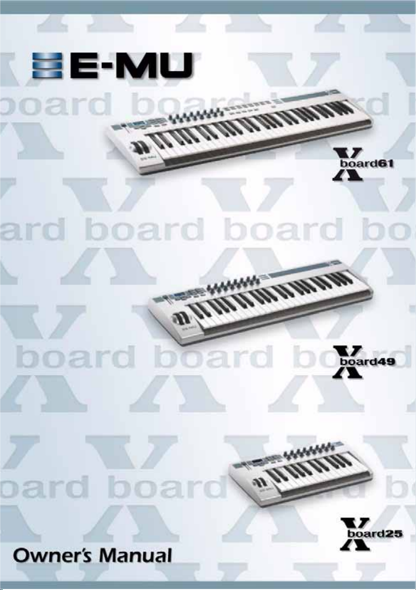
USB Connection
USB provides a two-way data link
between the Xboard and your
computer and also supplies
power to the Xboard. Always
connect to the USB port on the
computer itself—the USB port on
your computer keyboard will not
supply sufficient power.
U
S
B
C
a
b
l
e
(
i
n
c
l
u
d
e
d
)
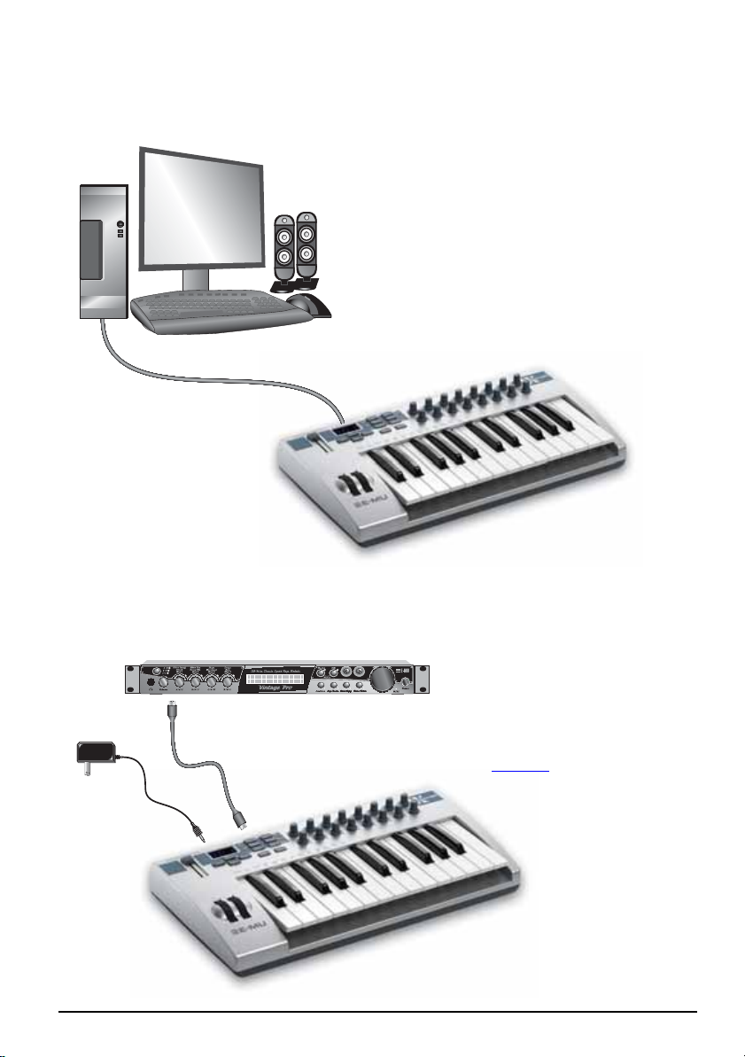
MIDI Connection
MIDI Sound Module
CO1 A V1 27 P PA:01RNIVTG
3
022
trn:Mellotron tr S
In
MIDI
Cable
6 VDC
Adapter
(optional)
(not included)
Out
Xboard 9
The Xboard sends MIDI performance data to another MIDI
device, such as a MIDI sound
module. The Xboard always
transmits MIDI data except
when “Thru” mode is enabled.
(See page 39
.)
Page 10
Introduction
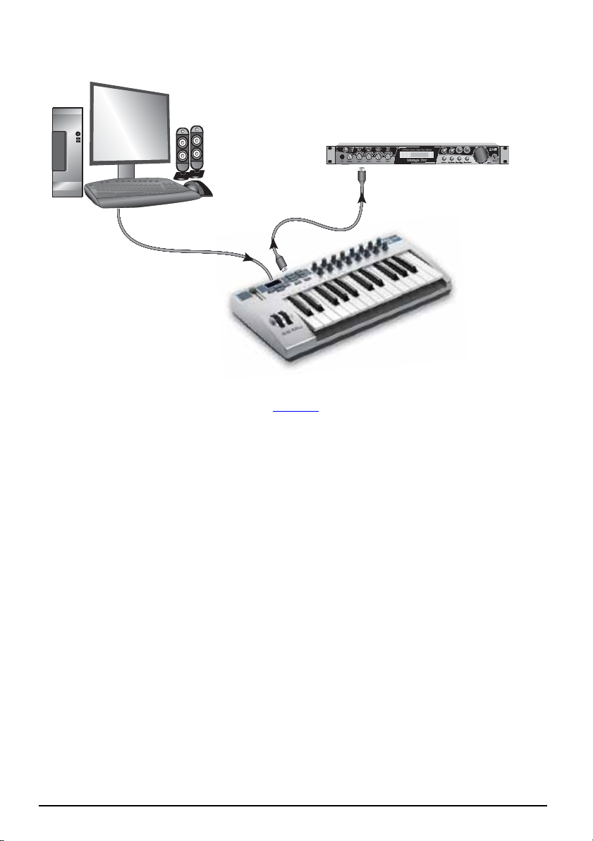
MIDI Interface
MIDI Sound Module
CO1A V 127 P PA:01RNIVTG
0223trn:Mellotron tr S
In
MIDI
Cable
U
S
B
C
a
b
l
e
(
i
n
c
The Xboard can function as a MIDI interface when connected to your computer via
USB. Set the Xboard MIDI port to “Thru” (page 39) to transmit MIDI from your
sequencing application to an external MIDI device.
l
u
d
e
d
)
Out
E-MU Systems 10
Page 11

Introduction
Software Installation
Macintosh OS X
Follow these instructions to install the Xboard Control software on a Macintosh
computer.
1. Insert the Xboard installation CD.
2. Double-click the E-MU icon on your desktop.
3. In the E-MU folder that opens, double-click the E-MU Xboard Apps & Docs
installer.
4. Follow the prompts to install the software.
Windows 2000
Follow these instructions to install the Xboard USB drivers and Xboard Contr o l
software on a Windows 2000 computer.
1. Make sure the X-Board is NOT CONNECTED to your computer.
2. Insert the E-MU software Installation CD into your CD-ROM drive. If
Windows AutoPlay mode is enabled for your CD-ROM drive, the CD starts
running automatically. If not, from your Windows desktop, click Start Run
and type d:\setup.exe (replace d:\ with the drive letter of your CD-ROM
drive). You can also simply open the CD and double-click Setup.exe.
3. The installation splash screen appears. Follow the instructions on the screen
to complete the installation. You will have the option to install E-MU Xboard,
and the other software included on the CD.
4. Choose “Continue Anyway” when you encounter the “Windows Logo
Testing” warning screen. See the note on the following page.
5. When prompted, restart your computer.
6. Connect the Xboard to your computer using the supplied USB cable.
Xboard 11
Page 12

Introduction
Windows XP
Follow these instructions to install the Xboard USB drivers and Xboard Control
software on a Windows XP computer.
1. Connect the Xboard to your computer using the supplied USB cable, and turn it on.
2. If Windows prompts you with an Add New Hardware Wizard, click Cancel.
3. Insert the E-MU software Installation CD into your CD-ROM drive. If
Windows AutoPlay is enabled for your CD-ROM drive, the CD starts running
automatically. If not, click the Start menu, and select Run. Type
d:\setup.exe (where d: is the drive letter of your CD-ROM drive) and
click OK. You can also explore the CD and double-click Setup.exe.
4. The inst allation splash screen appears. Follow the instructions on the screen
to complete the installation. You will have the option to install E-Mu Xboard,
and the other software included on the CD.
5. Click Continue Anyway when you encounter the “Windows Logo Testing”
warning screen. See
6. When prompted, restart your computer.
“Note About Windows Logo Testing”.
Uninstalling all Audio Drivers and Applications
At times you may need to uninstall or reinstall some or all of the Xboard's applications and device drivers to correct problems, change configurations, or upgrade
outdated drivers or applications. Before you begin, close all Xboard-related
applications. Applications running during the uninstallation will not be removed.
1. Click Start Settings Control Panel.
2. Double-click the Add/Remo ve Programs icon.
3. Click the Install/Uninstall tab (or Change or Remove Programs button).
4. Select the E-MU Xboard entry and then click the Change/Remove button.
5. In the InstallShield Wizard dialog box, select the Remove ALL option.
6. Click the Yes.
7. Restart your computer when prompted.
8. You may now re-install existing or updated E-MU device drivers or applications.
Note About Windows Logo Testing
When you install the Xboard USB drivers, you see a dialog box that informs you
that the driver has not passed Windows Logo testing.
However, the Xboard USB drivers have been rigorously tested using the same test
procedures that a signed driver requires, and it passes in all important categorie s,
including those that measure the relative stability of the dr ive r. So, it is perfectly
safe to install these drivers on your computer.
E-MU Systems 12
Page 13

Introduction
Troubleshooting
Lost Communication
Should you lose MIDI communication between your Xboard and an audio application (Cubase, Sonar, etc.) or the Xboard Control software, the Xboard drivers
may need to be re-selected in your application.
1. Go to your application's MIDI I/O settings, de-s elect the Xboard for both
MIDI input and output (or select a different MIDI device).
2. Apply these changes and exit the dialog.
3. Re-enter the application's MIDI settings and re-select the Xboard drivers. If
this does not work, the application may need to be restarted.
Wrong Driver in Windows XP or Windows 2000
You may encounter a situation where the Xboard Control or Proteus X software is
not running properly, even though the MIDI device itself seems to be working fine.
If this is the case, you may be in a situation where the Microsoft USB Audio Device
driver is running, rather than the E-MU USB Xboard Driver. This may happen if
you add a USB Hub, or if you plug the Xboard keyboard into a different USB port
than the one it was plugged into when you installed the Xboard software.
To confirm the problem, do the following:
1. Temporarily disconnect any USB audio devices you may have connected (USB
audio/USB MIDI interfaces, etc.).
2. Connect the Xboard to a USB port and switch the power to the on position.
3. Windows may prompt the user with an Add New Hardware Wizard--Cancel
this wizard.
4. Start menu Settings Control Panel System Hardware Device
Manager.
5. Under Sound, Video and Game Controllers, find the device called either USB
Audio Device or E-MU Xboardxx.
6. Double-click on this device and then click on Driver.
7. If the vendor shown here is E-MU Systems, you have run into a differentproblem, and you should contact Technical Support.
If the vendor shown here is Microsoft, instead of E-MU Systems, you have
indeed run into this situation. Continue on to the next section.
Xboard 13
Page 14
Introduction
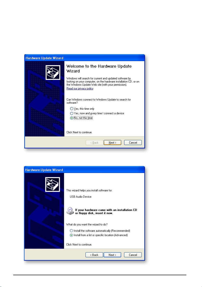
Windows XP You may recover by doing the following:
1. Click on Update Driver.
2. If you are running Windows Service Pack 2, following dialog box appears.
Select No, not this time, and click Next.
3. Select Install from a specific location (Advanced), and click Next.
E-MU Systems 14
Page 15
Introduction
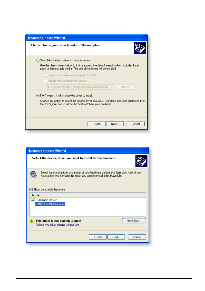
4. Select Don't Search, I will choose the driver to install, and click Next.
5. Select E-MU USB-MIDI Device, and click Next.
6. After a few moments, you will see the Microsoft Digital Signature warning.
Click Continue Anyway.
7. You should now be using the correct driver. It may be necessary to reboot
your computer at this point.
Xboard 15
Page 16

Introduction
Windows 2000 You may recover by doing the following:
1. Double-click the incorrect listing in the Device Manage r and choos e Update
Driver... from the Driver tab.
2. Click Next, then Display a list of known drivers for this device...
3. Click Next.
4. Click Have Disk...
5. Insert your Xboard install CD. If the disk autoruns, Exit the disk's ins tal le r.
6. Click Browse.
7. Browse to the following file, double-click the file, and click OK:
X:\Audio\Drivers\Driver\emuumidi.inf (where X is your CD drive letter).
8. Click Next.
9. Click Next again. The Windows logo testing dialog should appear.
10. Click Yes.
11. Click Finish. It may be necessary to reboot your computer at this point.
E-MU Systems 16
Page 17
Main Panel Controls
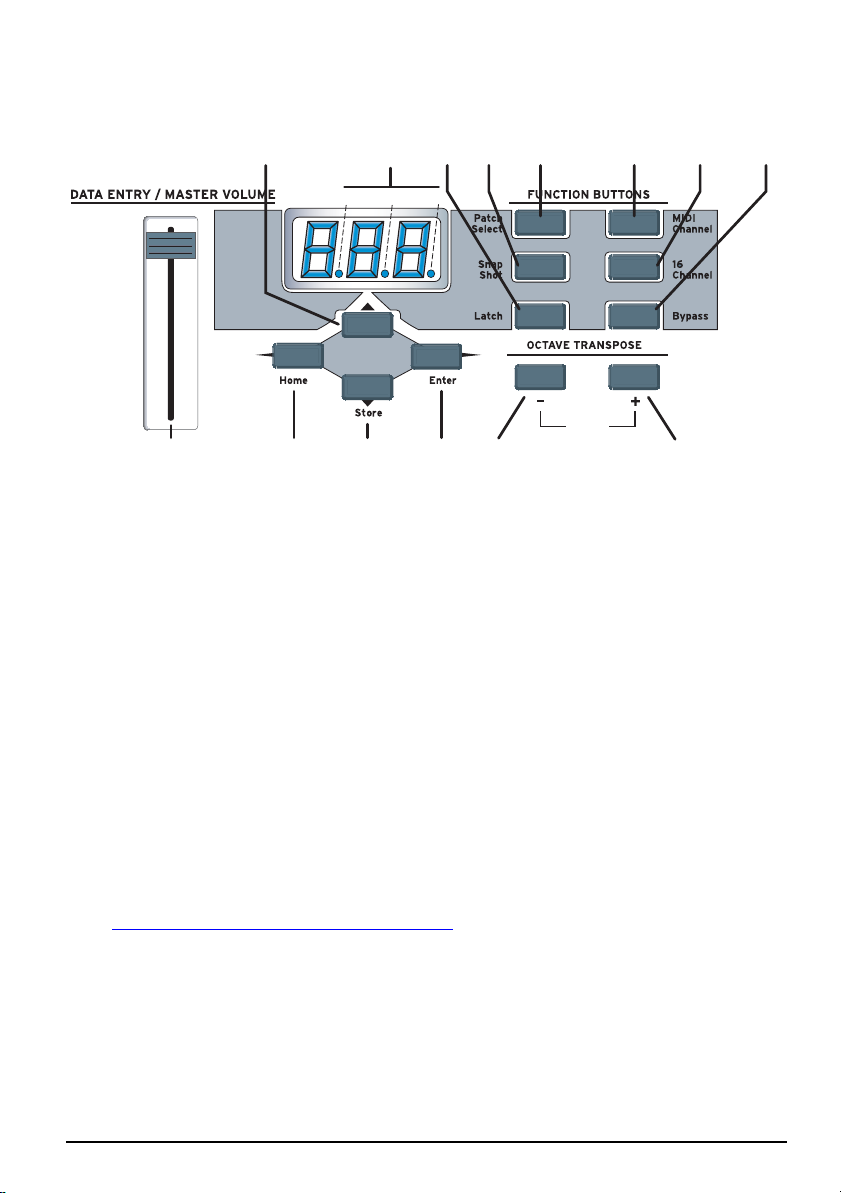
MAIN PANEL CONTROLS
2 3 12 14 11 13
ab
1
1. Data Entry / Master Volume Slider
This control is used to enter data values when editing. When not bein g used
for editing, the Data Slider functions as a master volume control transmitting
a “Universal Real Time System Exclusive” message for Master Volume.
2. Edit
Press this button to edit the current patch and certain device settings.
To Edit: Press the Edit button, choose the parameter to be edited using the
keyboard keys, enter the value with the slider, then press Ent er .
4567 8
c
910
Panic
3. MIDI Indicators
The decimal points in the LED flash to indicate USB and MIDI activity.
a. USB In
b. USB Out
c. MIDI Out
The activity indicators can be enabled or disabled from the X1 menu.
See “X1 and X2 Functions” on page 39.
4. Home
The Home button takes you out of edit mode and back into play mode
without saving your edit. You can also think of this button as an Escape
button which returns you to Play mode, the normal operating mode of the
keyboard. The Home LED is lit whenever the Xboard is in Play mode.
Xboard 17
Page 18

Main Panel Controls
5. Store Patch
This button stores your keyboard setup in one of the 16 memory locations.
To Store a Patch: After pressing Store, select the desired patch number using
the data slider, the Octave Transpose + and - buttons, or the Direct Patch
Select buttons (Xboard 61 only), then press Enter to store the current setup.
6. Enter
Press Enter to confirm your settings when editing. In most cases, the Home
LED illuminates after Enter is pressed, indicating a return to Play mode.
7. Octave Down
This button transposes the keyboard down one octave each time it is pressed.
The new octave transpose value (-1, -2, -3, -4) momentarily appears in the
display and the LED on the button remains lit unless transpose is set to zero.
8. Octave Up
This button transposes the keyboard up one octave each time it is pressed.
The new octave transpose value (+1, +2, +3, +4) momentarily appears in the
display and the LED on the button remains lit unless transpose is set to zero.
MIDI Panic Button (7 + 8)
Pressing both of the Octave Transpose buttons simultaneously causes the
following MIDI messages to be sent on all 16 channels: “All Notes Off”, “All
Sounds Off”, “Sustain Pedal Off”. This will turn off any “stuck notes” which
occur when a synthesizer receives a note-on message without receiving a
corresponding note-off message.
Increment / Decrement Buttons
The Octave Transpose buttons can be used as increment/decrement buttons
whenever the Data Slider is active for modifying an edit value (either numeric
or non-numeric settings). The increment/decrement buttons allow you to
increase or decrease the value one unit at a time.
9. Patch Select
This button is used to select one of the 16 user patches in memory.
To Select a Patch: Press the Patch Select button, then choose a patch using the
data slider, the Octave Transpose + and - buttons, or the Direct Patch Select
buttons (Xboard 61 only), and press Enter.
E-MU Systems 18
Page 19

Main Panel Controls
10. MIDI Channel Select
This button selects the Basic MIDI channel for the keyboard and all controls.
To Select a MIDI Channel: Press the MIDI Channel button, then select the
channel using the data slider, the Octave Transpose + and - buttons, or the
Direct Patch Select bu ttons (Xboard 61 only), and press Enter.
11. 16 Channel Control Mode
In this mode, one MIDI Continuous Controller number is assigned to all 16
knobs and each numbered knob transmits on the same-numbered MIDI
channel. This gives you control of one parameter (such as volume or pan) for
all 16 MIDI channels. See
12. Latch Mode
In this mode, pressed keys continue to play until they are pressed again to
turn them off. This allows notes to be sustained for any length of time
without having to hold down the keys. A range of latch keys can be defined
using the “Latch High Note” and “Latch Low Note” edit parameters. See
page 29.
13. Knob Bypass
Knob Bypass disables the transmission of MIDI messages from the knobs or
control pedal/footswitch to avoid abrupt parameter jumps in performance.
When Bypass is On, you can pre-set the knobs anywhere you like without
sending MIDI controller messages. When you turn Bypass Off again, nothing
is transmitted, but the knobs are now in the desired position for your perfor
mance. When you turn a knob, the value of the new knob position will be
sent.
This feature can also be used to set up any of the knobs the way you want,
then send the values later using the Snapshot feature. See
page 27 for detailed information.
page 31.
-
14. Snapshot
When this button is pressed, the stored current settings of all performance
controls (knobs, wheels, footswitch/pedal) are transmitted. This feature can
also be used in conjunction with the Knob Bypass control to setup, and then
send a group of MIDI continuous controllers messages at once.
The Snapshot function is accessible only while in Play mode (i.e., whenever
the Home LED is lit).
Xboard 19
Page 20

Controller Knobs
CONTROLLER KNOBS
The 16 Controller Knobs are designed to modify the sound during performance.
MIDI Continuous Controller messages are transmitted whenever the knobs are
turned (except when “Knob Bypass” is enabled).
Whenever a controller knob is turned, the current value of the knob is displayed
on the LED. Next, the letters “CC” flash on the display, followed by the MIDI
Continuous Controller assigned to the knob, then the letters “CH”, and finally the
MIDI channel on which the knob currently sends. To set the CC channel numbers
of the knobs see page 27
Normal mode
Any MIDI Continuous Controller number can be assigned to any knob. For
instructions on setting this from the Xboard, see page 27
using the Xboard Control Software, see page 49
.
. For help setting this
.
16 Channel Controller mode
In this mode, one MIDI Continuous Controller number is assigned to all 16 knobs
and each numbered knob transmits on the same-numbered MIDI channel. This
gives you control of one parameter (such as volume or pan) for all 16 MIDI
channels. See page 27
.
3D MIDI and NRPN mode
Using the Xboard Control software, any of the 16 Controller Knobs can be
configured to run in 3D MIDI mode, or NRPN mode. For more information, see
page 50.
E-MU Systems 20
Page 21
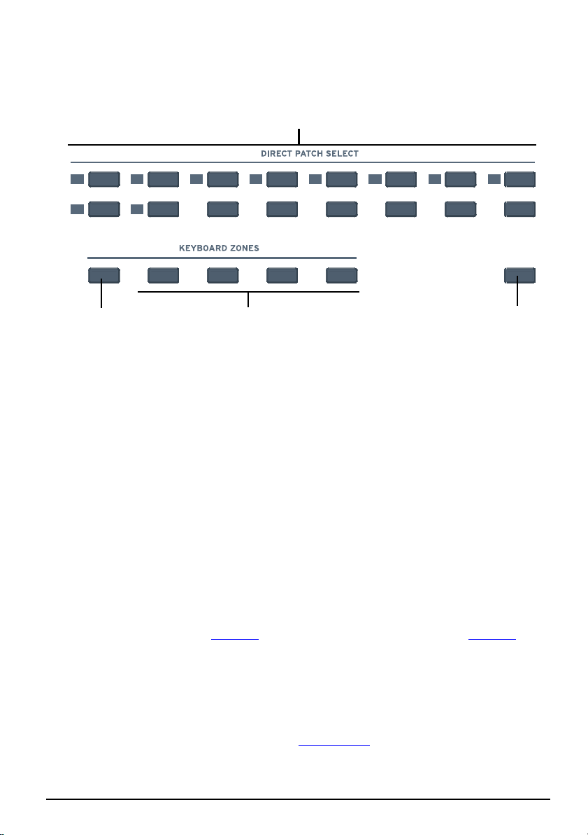
Xboard 61 Panel Controls
XBOARD 61 PANEL CONTROLS
1
Zones
Enable
1
9
2
10
123
3
11
4
12
5
13
4
6
14
7
15
23 4
1. Patch Select / Numeric Keypad
These buttons serve a number of functions:
• With Program Change mode turned off, you can select a patch from 1 to
16 at any time. The LED for the current patch stays illuminated.
• When changing MIDI channel, or Storing and Loading Patches with the
main panel controls, use buttons 1 through 16 to make a selection.
• For Program change mode, use buttons 1 through 10 to enter numerical
values for Program Changes.
• Use the numerical keypad buttons when entering numerical values, such
as Edit functions.
2. Zones Enable
Enables or disables Zones functions in the active patch. When Zones are
enabled, the LED illuminates.
For the Xboard 25 or Xboard 49, you can enable or disable Zones using the
X2 menu item “ZoE”(
page 43) or the Xboard Control software (page 56).
8
16
■ Program
Change Mode
3. Keyboard Zones Buttons
These buttons enable or disable individual Zones. When a Zone is enabled,
the LED illuminates.
For the Xboard 25 or Xboard 49, you can enable or disable individual Zones
using the Xboard Control software (
See page 58).
Xboard 21
Page 22
Xboard 61 Panel Controls
4. Program Change Mode
When you press this button, you switch between Program Change mode and
Patch Select mode. The LED illuminates when in Program Change mode.
• Program Change mode: allows you to send MIDI program changes to
other equipment using the numerical buttons. (0-9)
• Patch Select mode: allows you to select from 16 internal patches (1-16).
The Program Change Mode button also doubles as the Enter button when it,
along with the Enter button, fla shes.
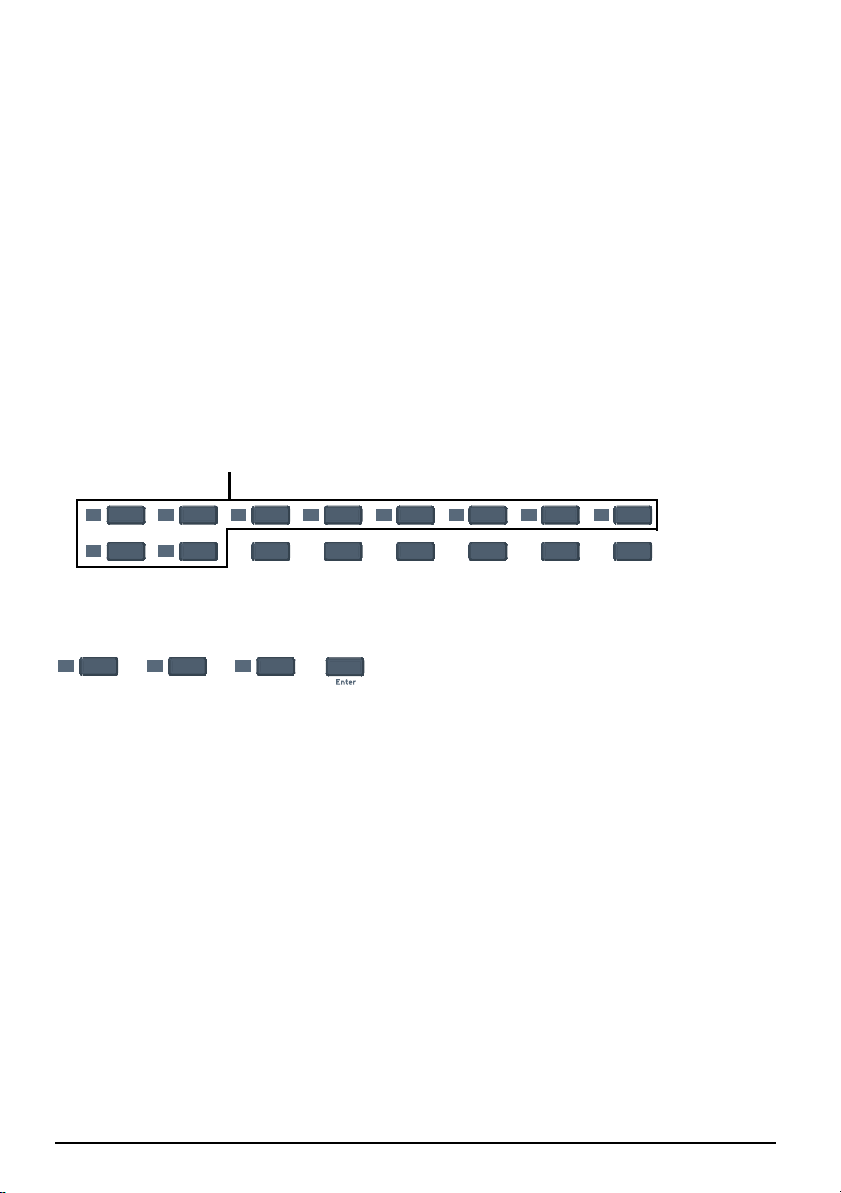
Using the Numeric Keypad
The numeric keypad allows you to enter numeric values for Program Changes, and
other settings.
Use 1-10 to Enter Numerical Values
1
9
2
10
3
11
4
12
5
13
6
14
7
15
8
16
To use the numeric keypad to enter data, use the buttons labeled 1 through 10 to
enter a value. The current value is reflected in the display. The “10” button acts as
the value of 0, so if you want to enter a value of 109, you would press:
1
10
+
9
++
If you enter a value you don’t like, you can clear the value by entering “0” three
times.
E-MU Systems 22
Page 23

Back Panel Description
BACK PANEL DESCRIPTION
12 345
1. Footswitch / Footpedal Input
This jack accepts either a footswitch or continuously variable footpedal. The
default setting is for a footswitch. To use a footpedal, see
Footswitch - Accepts either a normally-open or normally-closed momentary
footswitch. The Xboard auto-senses the polarity on power-up.
Footpedal - Accepts most standard footpedal types with a stereo plug. See the
wiring diagram shown on
2. MIDI Output
Outputs note and controller MIDI data from the Xboard. This jack can also be
used as a MIDI interface from a computer software application. See
Use a standard MIDI cable to connect the Xboard to the MIDI input jack of
other MIDI devices.
page 65 for pedal wiring specifications.
page 40.
page 39.
3. USB
Connects Xboard to your computer via the supplied USB cable. The USB
connection provides two-way communication when connected to the
computer and also supplies power to the Xboard. Always connect to the USB
jack on the computer itself and NOT to a low-power USB connection that
may be present on your computer keyboard or other USB peripheral.
4. 6 Volt DC Power
This jack allows the Xboard to be powered from a standard 6VDC Adapter
(positive tip) when not connected to the computer via USB.
5. On/Off Switch
This switch turns the Xboard on or off whether powered via USB, AC Adapter,
or batteries.
Xboard 23
Page 24

Powering the Xboard
POWERING THE XBOARD
The Xboard can be powered using any of the following power sources:
• USB from the host computer
•6 VDC Adapter (Optional - Part Number: 70EM779006000)
• (3) AA batteries
The priority of power sources is as follows:
1. 6VDC power - will be used over all other power sources if available.
2. USB power - will be used if connected and 6VDC is not available.
3. Battery power - will be used only if no other power source is available.
Inserting Batteries into the Xboard
Sometimes it’s nice not to have to hassle with power at all. Thankfully the Xboard
can be operated using (3) AA batteries. Battery life generally exceeds 5 hours using
standard alkaline batteries. Lithium batteries typically last 16+ hours.
To Insert Batteries:
The battery compartment is located on the bottom of the unit.
1. Press the two tabs toward the middle of the battery door while lifting up. The
compartment door lifts up and out.
2. Insert (3) AA batteries. Make sure you install them as indicated at the bott om
of the battery compartment with + aligned with the + side of the battery.
The battery compartment on the Xboard 25 and Xboard 49
Insert Batteries
here
This Side
Not Used
3. Insert the tabs of the battery compartment door into the hinge slots, then
press down to snap the door closed.
E-MU Systems 24
Page 25

Basic Operations
Panic
BASIC OPERATIONS
Entering Data
There are several ways to enter data from the Xboard.
• Data Slider - Move the slider to select the data value.
• Octave Transpose buttons - Increment and decrement by pressing the “+”
and “-” buttons.
• Keyboard Data Entry - The black and white keyboard keys marked with
numbers can be used to directly enter data values (except when changing the
MIDI channel number or storing and selecting patches, since the keyboard remains
“live”
at these times).
• Numeric Keypad (Xboard 61 only) - Type in the value using keys 1-10. See
page 22.
Selecting and Storing Patches
The Xboard can hold 16 patches in its internal memory. A patch contains the
settings for all user programmable controls of the Xboard.
In addition, depending on the patch settings, the Xboard can send MIDI program
changes message(s) and initial controller settings for the knobs, wheels and
footswitch/pedal when a particular patch is selected.
To Select a Patch Using the Main Panel:
1. Press the Patch Select button, illuminating the LED. The Enter button and
Program Change Mode button (Xboard 61) begin flashing.
2. Select the desired patch number using the Data Slider or the Octave
Transpose + and - buttons. On the Xboard 61, you can also use the Direct
Patch Select buttons 1 through 16.
On the Xboard 61, the new patch you selected begins flashing.
3. Press Enter to confirm the operation. Press Home to cancel the operation.
1
2
Xboard 25
3
Page 26

Basic Operations
To Select a Patch Using Direct Patch Select Buttons (Xboard 61):
1. Make sure Program Change mode is off. The Program Change Mode button’s
LED should not be lit.
2. Press one of the Direct Patch Select buttons 1 through 16.
To Store a Patch:
1. Press the Store button. The Enter and Direct Patch Select (Xboard 61) LEDs
begin flashing.
2. Select the desired patch number using the Data Slider or the Octave
Transpose + and - buttons. On the Xboard 61, you can also use the Direct
Patch Select buttons 1 through 16.
On the Xboard 61, the new patch you selected begins flashing.
3. Press Enter to store the patch. Press Home to cancel the operation.
2
1
3
Panic
Changing the MIDI Channel
The MIDI specification allows for up to 16 channels to be used. This control allows
you to set the Basic MIDI channel for data transmitted by the Xboard keyboard
and controllers. Note that this setting is stored in and recalled from patches .
To Change the MIDI Channel:
1. Press the MIDI Channel button. The MIDI Channel LED illuminates. On the
Xboard 61, the Direct Patch Select button representing the Current MIDI
channel also illuminates.
2. Select the desired MIDI channel using the Data Slider or the Octave
Transpose + and - buttons. On the Xboard 61, you can also use the Direct
Patch Select buttons 1 through 16.
The Enter and Direct Patch Select (Xboard 61) buttons will be flashing. On
the Xboard 61, the Direct Patch Select button representing the new MIDI
channel begins flashing as well.
3. Press Enter to confirm the operation, or press Home to cancel the operation.
E-MU Systems 26
Page 27

Basic Operations
Transposing the Keyboard
The keyboard can be transposed up and down ±4 octaves
by pressing the Octave Transpose buttons. The octave
number appears momentarily in the display. The LED on
the transpose button remains lit to remind you that the
keyboard is transposed. The transposition value is stored
with the patch.
Octave Transpose works differently depending on your zones settings:
• With Zones disabled, the keyboard is simply transposed by octaves.
• With Zones enabled and Octave Transpose Mode set to Pre Zone(page 56),
the keyboard is transposed, but each Zone’s tuning stays the same.
• With Zones enabled and Octave Transpose Mode set to P ost Zone(page 56),
any Zone that has Post Zone Octave Transpose enabled (page 59) is transposed, while the keyboard’s tuning stays the same.
Changing Controller CC Channel Numbers
You can change MIDI continuous controller numbers (0-127) for each knob,
pedal, or the Mod Wheel on the Xboard. The Xboard CC numbers must match the
CC numbers on your synthesizer in order to operate.
To Change Controller CC Channel Numbers:
1. Press the Edit button.
2. Move the controller you want to change. This can be any of the 16 controller
knobs, a pedal, or the Mod Wheel. The Enter button blinks and the display
shows you the controller’s current CC Channel number .
3. Select the desired CC Channel number using the Data Slider or the Octave
Transpose + and - buttons. On the Xboard 61, you can also use the Direct
Patch Select buttons 1 through 16.
4. Press Enter to confirm the operation. Or, press Home to cancel the operation.
16 Channel Control Mode
16 Channel Control mode is a special performance mode in which all 16 knobs
send one CC number on MIDI channels 1 through 16. This allows you to control a
single parameter on all 16 MIDI channels. For example, if the controller number
were set to #7 (Channel Volume), the knobs could be used to mix the volumes of
all 16 MIDI channels.
Xboard 27
Page 28

Basic Operations
In 16 Channel Control Mode, each knob transmits on its same-numbered MIDI Channel.
All knobs transmit the same MIDI Controller Number.
To Select 16 Channel Control Mode:
1. Press the 16 Channel button. The 16 Channel LED illuminates.
2. Press the button again to exit 16 Channel Control Mode. The LED goes off.
To Set the 16 Channel Control Number:
1. Press the Edit button. The Edit LED illuminates.
2. Press the keyboard key marked 16-Ch. CC Number.
3. Select a CC number from 0-127 using the Data Slider, the Octave Transpose
buttons, or the Numeric Keyboard keys. The Enter button flashes.
4. Press Enter to confirm the operation. Press Home to cancel the operation.
Working With Zones
To Enable or Disable the Zones Function:
•Use the ZoE function in the X2 menu. See page 43.
• For the Xboard 25, 49, or 61, use the Zones Enable button in the Xboard
Control software. See
• On the Xboard 61, press the Zones Enable button. When enabled, the LED
illuminates.
Note: Semitone Transpose is disabled when Zones are enabled.
To Enable or Disable a Specific Zone:
• On the Xboard 61, press the corresponding button for Zone 1, 2, 3, or 4.
When a zone is enabled, its LED illuminates.
• For the Xboard 25, 49, or 61, Enable Zones in the Xboard Control software.
See
page 58.
E-MU Systems 28
page 56.
Page 29

Basic Operations
Note Latch Mode
This is a performance mo de in whic h a sel ected r ange of k eys can be set t o Latch. A
latched key remains on when pressed once. Pressing the key again turns the note
off. Latched notes can be useful to trigger loops or repeating rhythmic patterns
without having to hold the key.
Latched notes work differently depending on whether Zones are enabled or
disabled.
Latch Mode, Zones Disabled
Any range of keys (0-127) can be specified as latch notes. Therefore, you could set
a range of latch keys that are only accessible with the keyboard transposed down,
so as to be out the way in normal operation. Note that you cannot set a low key
number higher than the high key, or a high key number lower than the low key.
Note latching is independent per MIDI channel. Notes can remain latched on a
given channel while you switch to a different channel, either via direct channel
setting change or via patch load. Additional notes can be latched on the new
channel.
Turning Latch Mode off manually with the Latch button switches off all latched
notes, regardless of their channel or the sequence in which they we r e lat ched.
Latched notes are NOT switched off upon loading a new patch in which Latch
Mode is OFF. To turn these notes off, either return to the original MIDI channel
and play the same notes again, or manually switch Latch Mode ON and then OFF.
Latching Notes
Latch
Low Note
To Sel ect Latc h Mod e:
Latch
High Note
These notes play normally
1. Press the Latch button. The Latch LED illuminates.
2. Press the button again to exit Latch Mode. The LED goes off.
Xboard 29
Page 30

Basic Operations
To Set the Keyboard Range of Latched Notes:
1. Low Key Press the Edit button, illuminating the LED.
2. Press the keyboard key marked Latch Low Note.
3. Press the keyboard key of the lowest note you want to be in Latch Mode.
4. Press Enter to confirm the operation. Press Home to cancel the operation.
5. High Key Press the Edit button, illuminating the LED.
6. Press the keyboard key marked Latch High Note.
7. Press the keyboard key of the Highest note you want to be in Latch Mode.
8. Press Enter to confirm the operation. Press Home to cancel the operation.
Latch Mode, Zones Enabled
If you have Zones enabled, the Latch Low Note and High Note settings are
ignored. Instead, Latch Mode is handled on a per-zone basis. Use the Xboard
Control software to turn latch mode on or off for each Zone. See “
Mode Enable” on page 59.
For zones with Latch Mode enabled, turning on Latch mode using the Latch
button on your Xboard turns on latch for those zones.
Turning Latch Mode off manually with the Latch button switches off all latched
notes, regardless of their channel or the sequence in which they were latched.
Latched notes are NOT switched off upon loading a new patch in which Latch
Mode is OFF. To turn these notes off, either return to the original MIDI channel
and play the same notes again, or manually switch Latch Mode ON and then OFF.
Note Latch
Snap Shot
The Xboard can store the settings of the 16 knobs and footpedal/footswitch with
the Patch. When the Snap Shot button is pressed, the currently stored settings of all
performance controls (knobs, wheels, footpedal) are transmitted. The initial
setting of the footswitch is not transmitted.
Note: Snap Shot cannot transmit values for controls that are set to NRPN mode.
Here’s an example of how you might use this feature. The knob settings can be
stored with the Patch, and can either be transmitted when the Patch is selected or
not. For the purpose of this example, suppose the knob settings are NOT transmitted
when the Patch is selected. At a certain point in your song, you could press Snap
Shot and completely change the sound by sending the stored controller messages.
This feature can also be used in conjunction with the Knob Bypass control to set
up, and then send a group of MIDI continuous controllers messages at once. See
the description of Bypass Mode
E-MU Systems 30
.
Page 31

Basic Operations
Bypass Mode
When you move a controller knob on the Xboard, the position value is immediately transmitted via MIDI. Knob Bypass disables the transmission of MIDI
messages from the knobs or control pedal/footswitch.
Bypass mode allows you to pre-set the knobs to a known position in order to
avoid abrupt parameter jumps in performance when you turn the knob.
When Bypass is On, you can set the knobs anywhere you like without sending
MIDI controller messages. When you turn Bypass Off again, nothing is transmitted, but the knobs are now in the desired position for your performance. When
you turn a knob, the value of the new position will be sent.
This feature can also be used in conjunction with the Snap Shot feature. In Bypass
mode, moving the controller knobs temporarily changes the stored s etti ngs.
Pressing Snap Shot in Bypass mode transmits the stored settings with any changes
you made while in Bypass mode.
Note: Snap Shot cannot transmit values for controls that are set to NRPN mode.
Editing Patch and Device Settings
Many editable settings are accessed using the labelled keyboard keys or other
controls.
To Edit a Setting:
1. Press the Edit button. The Edit LED illuminates.
2. Select the desired setting by pressing one of the marked keyboard keys. (The
Velocity Curve is being edited in the example below.)
3. Adjust the value of the parameter using the Data Slider, the Numeric
Keyboard Keys, the Octave Transpose buttons, or the Numeric Keypad
(Xboard 61 only). The Enter button will be flashing.
4. Press Enter to confirm the operation. Press Home to cancel the operation.
5. Remember to Store the Patch or your changes will be lost the next time you
recall a stored patch, or when the Xboard is turned off. See
Xboard 31
page 26.
Page 32

Basic Operations
1
Editing Patch and
Device Settings:
1. Press Edit.
2. Select Function.
3. Adjust Value.
4. Press Enter.
2
4
3
Semitone
Semitone
Transpose
Transpose
Scrolling Text Display
In Edit mode, and in some other situations, the 3-digit numeric display serves
double duty as a scrolling text display. When you first pres s the Edit button, the
word “SELECt” scrolls continuously across the display, prompting you to select an
edit parameter as described above. Once an edit parameter is selecte d, the current
value of the parameter is displayed. After a short delay, the edit parameter name
begins scrolling periodically across the display as a reminder of which parameter
you’re editing. Once you enter a value, the display stops scrolling.
You’ll notice that the scrolling messages mix upper and lower case characters. This
is a necessary compromise to display alphabetical characters on a numeric display.
Vel
Vel
Curve
Curve
Select
Select
16-Ch CC
16-Ch CC
Number
Number
Latch
Latch
Low
Low
Note
Note
Latch
Latch
High
High
Note
Note
Save CC
Save CC
Val in
Val in
Patch
Patch
CC Send
CC Send
On
On
Recall
Recall
PGM Send
PGM Send
On
On
Recall
Recall
Bank
Bank
Sel
Sel
MSB
MSB
Bank
Bank
Sel
Sel
LSB
LSB
Send
Send
Prog
Prog
Change
Change
After
After
Touch
Touch
E-MU Systems 32
Page 33

Basic Operations
Edit Parameters
These parameters are accessed via the Edit button. See “Editing Patch and Device
Settings” on page 31 for detailed instructions about how to access the Edit mode.
PGM Send on Recall
Every Xboard patch stores a MIDI program change number (as well as Bank Select
MSB and LSB settings) for each of the 16 MIDI channels. The “PGM Send On
Recall” setting is a master switch which enables or disables transm is sion of the
stored MIDI program change settings when a patch is recalled.
Select on to transmit the program changes, etc. stored in a patch when that patch is
recalled. This allows you to reconfigure all of your MIDI instruments at once by
simply recalling that patch. Select oFF if you don’t want the stored program
changes transmitted on patch recall.
This feature has a couple of tricky aspects which you need to be aware of in order
to use it as intended:
• In addition to the master on/off switch, there is also an on/off switch per
MIDI channel. When the master switch is set to on, progra m changes will be
sent upon patch recall only on channels whose per-channel on/off switch is
also set to on in the patch. This allows you to restrict program change sends
to only the desired channels. However, unlike the maste r swi tch, the se per channel switch settings can only be modified using the Xboard Control editor
application. Since all of these switches are set to off by default, full setup of
this feature is possible only using that application.
• The master and per-channel on/off settings, as well as the program change
and bank select numbers, are stored in and recalled from patches. They are
not global settings and can be different from one patch to the next. Since they
are applied immediately following recall of a patch, these settings must
already be stored in a patch in order to have any effect upon what happens
when the patch is recalled, and will apply only to that patch. It follows that
the patch must be stored again anytime these settings get changed –
otherwise, any changed settings will be lost.
Xboard 33
Page 34

Basic Operations
Send Program Change
This function sends MIDI program changes to your external gear on the currently
selected Basic MIDI channel. (At the same time, it edits the program change number for
the current MIDI channel in the active patch. See “
more info.)
Note that the program change send includes a send of Bank Select MSB and Bank
Select LSB according to the settings for those parameters on the same MI DI
channel in the current patch. See page 34
To Send an External Program Change Via the Main Control Panel:
1. Press the Edit button.
2. Press the Send Prog Change keyboard key.
3. Select the desired program change number from 0-127 using the Data Slider,
Octave Transpose buttons, or Numeric Keyboard Keys.
4. Press Enter to send the program change.
5. Press Home to exit without sending the program change. (This also leaves the
program change setting for the current MIDI channel unmodified in the active patch.)
To Send an External Program Change (Xboard 61):
1. Make sure the Program Change Mode button’s LED is lit. If not, press the
button to light it.
2. Use the Direct Patch Select numerical buttons to enter a one- to three-digit
program change number. Use the button labeled “10” to enter a “0.”
3. Do one of the following:
• If Zones are enabled, press the corresponding Zone button for the MIDI
channel you want to send the Program change across. If you want to send
the Program Change over the current MIDI channel, press Enter or the
Program Change Mode button (they will be blinking).
• If Zones are not enabled, press Enter or the Program Change Mode
button (they will both be blinking).
PGM Send on Recall” on page 33 for
.
Bank Sel MSB
This parameter allows you to select the MIDI Bank Select MSB (most significant
byte) that will be used when sending program changes via the Prog Change, PGM
Browse Mode or PGM Send On Recall features.
Select a Bank MSB from 0-127. Note that this merely edits the Bank Select MSB
setting for the current MIDI channel in the active patch. It does not cause a MIDI
message to be sent immediately.
For more information on MIDI Bank Select commands, see page 65
E-MU Systems 34
.
Page 35

Basic Operations
Bank Sel LSB
This parameter allows you to select the MIDI Bank Select LSB (least significant
byte) that will be used when sending program changes via the Send Prog Change,
PGM Browse Mode or PGM Send On Recall features.
Select a Bank Select LSB from 0-127. Note that this merely edits the Bank Select
LSB setting for the current MIDI channel in the active patch. It does not cause a
MIDI message to be sent immediately. For more information on MIDI Bank Select
commands, see page 65
.
Program Change (PGM) Browse Mode
This function allows you to play the keyboard and use the wheels and rotary
controls while browsing through MIDI programs. Program change messages are
sent on the Basic MIDI channel as described above (See “
on page 34.). This includes sending Bank Select MSB and Bank Select LSB
according to current settings for that MIDI channel in the active patch.
To Browse MIDI Program Changes:
1. Press the Edit button.
2. Press the PGM Browse Mode keyboard key. The display shows the current
program change setting for the patch’s basic MIDI channel.
3. Select the desired program change number using the Data Slider or the
Octave Transpose buttons. The program change numbers are shown on the
display. (In order to avoid sending continuous barrages of program change
messages which might confuse receiving equipment, program change
messages are transmitted only when the slider stops mo ving for one s econd.
The display will briefly show “---” whenever this occurs.) You can play the
keyboard and use other performance controllers to audition the selected
program.
4. Press Enter.
Press Home to leave the program change setting for the current MIDI channel
unmodified in the active patch. The unmodified setting is used in one final
program change message send to restore the previously-loaded program in
any device which is receiving on that channel.
Send Program Change”
Xboard 35
Page 36

Basic Operations
CC Send On Recall
Every Xboard patch stores an initial value (position) setting for each of the 16
Controller Knobs, the Pitch Wheel, the Mod Wheel and the Footpedal. The “CC
Send On Recall” setting enables or disables transmission of these stored values
when a patch is recalled.
Select on to transmit the values stored in a patch when that patch is recalled. In
conjunction with the “Save CC Values In Patch” feature, which lets you control the
settings which get stored in a patch (see below), this allows you to simultaneously
preset many individual parameters of your MIDI instruments exactly as desired, by
simply recalling that patch. (If “PGM Send On Recall” is also switched on in the
same patch, the program changes are sent first, followed by the controller
messages, so that the controller messages will affect the newly-loaded programs.)
When set to oFF, the continuous controller settings will not be transmitted when
the patch is selected.
Note: This feature has a tricky aspect which you need to be aware of in order
to use it as intended:
The “CC Send On Recall” setting is stored in and recalled from patches. It is
not a global setting and can be different from one patch to the next. Since it is
applied immediately following recall of a patch, this setting must be stored in
a patch in order to have any effect upon what happens when the patch is
recalled, and will apply only to that patch. It follows that the patch must be
stored again anytime this setting gets changed – otherwise, the changed
setting will be lost.
Save CC Value in Patch
This setting is useful in conjunction with the “CC Send On Recall” feature (see
above). When this parameter is set to On, the curr ent initial value (position)
settings of the 16 Controller Knobs, the Pitch Wheel. the Mod Wheel and the
Footpedal will be stored in a patch when the patch is stored. If this setting is oFF,
the existing controller initial value settings in the patch are retained, even if you
have adjusted one or more controls in the meantime. Therefore, turning this
option oFF effectively “locks” the controller initial value settings into the patch.
Note that this setting is applied when you store a patch, not just aft er the patch is
recalled, and is thus effective immediately upon being changed – unlike some
settings discussed above, it doesn't need to first be stored in a patch in order to
become effective.
Note: You cannot save values for controllers that are set to NRPN mode.
E-MU Systems 36
Page 37

Basic Operations
Tips for Use…
Assuming you wish to use the “CC Send On Recall” feature with a particular patch,
turn this option on while editing the controller initial value settings in that patch.
Once you’ve stored the patch with the desired initial controller settings, swit ch this
option oFF and store the patch one more time. This will save the oFF setting for
this option in the patch. Since the on/oFF setting will also be recalled whenever
you recall the patch, the oFF setting ensures that the initial controller settings
won’t be accidentally overwritten if you later change some other setting in the
patch and store it again. If you later want to change one or more of these settings,
simply switch the setting back on before storing the patch with the updated
settings (and don’t forget afterwards to switch the option back oFF and store the
patch again as described above, to lock in the updated settings).
Aftertouch On/Off
When Aftertouch is On, the keyboard will transmit channel afte r touch m es sages.
Aftertouch is transmitted when additional pressure is applied to the keyboard after
the keys have been pressed.
Select on to turn Aftertouch on, or oFF to turn it off.
Note: This setting, unlike most of the settings described in this section, is a devi ce
setting, which is not stored in or recalled from patches. It is thus also a global
setting which affects all patches in common – or rather, it affects device behavior
independently of patches.
Semitone Transpose
The keyboard can be transposed up or down in one-semitone steps. Transpose
works by shifting the keyboard position relative to middle C.
The transposition range is -64 to +63 semitones.
Note: Semitone Transpose is disabled when Zones are enabled.
Xboard 37
Page 38

Basic Operations
Velocity Curve Select
This function selects one of the eight velocity curves to customize the feel of the
keyboard. When playing a velocity-sensitive sound (such as piano), select a curve
that provides the most natural response to your playing style.
Select a curve from 1 to 8.
1 2 3 4
Linear -
No change
to velocity.
5678
Compressed -
For hard players.
Medium
medium velocity.
Compressed dynamics
- Outputs
Compress/Limit -
Outputs medium
values. Limits dynamics.
Low Vel 1
compression. Outputs
low velocity values.
- Extreme
Low Vel 2
compression. Outputs
low velocity values.
- Extreme
Compressed
top and bottom ends
cut.
- with
Full Velocity
outputs full velocity.
- Only
You can also select the MIDI minimum velocity, which essentially reduces the
vertical scale of the above drawings. See page 42
.
16 Channel CC Number
16 Channel Control mode is a special performance mode in which all 16 knobs
send one CC number on MIDI channels 1 through 16. This allows you to control a
single parameter on all 16 MIDI channels. See
“16 Channel Control Mode” on
page 27 for more information about how to use this function.
Latch High/Low Note
These keys allow you to set the keyboard range for Latch mode. See page 29, for
detailed information about Latch mode.
E-MU Systems 38
Page 39

Basic Operations
X1 and X2 Functions
The X1 key accesses the X1 functions. These are global functions that affect all
patches. For example, if Pedal is set to Sus, it will remain so for all patches.
• Mid - Out or Thru - When Out is selected, the MIDI output transmits local
data from the keyboard and knobs. When Thru is selected, the MIDI output
transmits data from the host application.
• PEd - Selects between a footswitch (SuS) or a continuous footpedal (ctL)
• ind - Turns the decimal point USB/MIDI indicators on or off. See page 17.
• Zod - Turns the zones status message on or off.
• PbM - Determines the behavior of the Numeric Keypad after you send a
program change.
• CAL - The Calibration sub-menu. The functions here allow you to make very
specific calibrations. These settings are for advanced users.
The X2 key accesses the X2 functions. The se are global functions which affect only
the active patch. For example, if you turn Zones off it will remain so for only the
active patch.
• ZoE - Enables and disables Zones functions in the active patch.
To Select one of the X1 or X2 Functions:
1. Press the Edit button. The Edit LED illuminates.
2. Select X1 or X2.
3. Adjust the data slider or use the Octave Transpose buttons to view the
functions.
4. Press Enter to select the desired function.
5. Select the desired value using the data slider or the Octave Transpose butto ns
(except with CAL).
6. Press Enter to confirm your selection. Press Home to cancel the operation.
X1 Menu Items
The following is a description of the items located in the X1 menu.
MIDI (Mid)
The Xboard can function as a MIDI interface between your computer applications
and external MIDI gear. When set to Thru, MIDI data from your computer application is transmitted on the Xboard’s MIDI output jack. When Out is selected, the
MIDI output transmits local data from the keyboard and knobs.
Xboard keyboard and controller data is NOT transmitted from the MIDI output
when this function is set to Thru. (Keyboard/Controller data is always sent via USB.)
Xboard 39
Page 40

Basic Operations
Pedal (PEd)
This function sets up the Footswitch / Footpedal input to accept a switch or a
variable pedal control input.
• SuS = Sustain or footswitch input. In this mode, the Xboard automatically
senses the footswitch polarity on power up (either normally-open, or
normally-closed). Because of the automatic sensing feature, you should not
hold down the footswitch during power up or the switch action will be
reversed.
• ctL = Control Pedal. The Xboard accepts control pedals wired as shown on
page 65.
Indicators (ind)
The decimal points in the LED indicate USB and MIDI activity. Select on or oFF.
1st = USB In; 2nd = USB Out; 3rd = MIDI Out.
Zones On/Off Status Display (Zod)
Select on or oFF.
If on, when you select a new patch, the Edit LED display shows a message
indicating whether zones enabled or disabled in the new patch. This is especially
useful for the Xboard 25 and Xboard 49, since they don’t have a Zones Enable
button.
Patch Buttons Program Change Mode Auto-Disable (PbM)
Select on or oFF.
With this setting on, the Program Change Mode button turns off automatically
after you send a program change, returning the numeric keypad to Direct Patch
Select Mode.
With this setting off, the Numeric Keypad remains in Program Change mode after
you send a program change.
Calibrate Sub-Menu (CAL)
When you select CAL and press Enter, you are taken to the CAL sub-menu, whi c h
contains calibration functions. To select a function, use the data slider to select a
Calibration function, and press Enter. To cancel, press Home.
CCM
This feature enables you to calibrate any control on your Xboard, one at a time,
optimizing your Xboard’s action for your playing technique.
After you select the CCM function and press Enter, all LEDs on the Xboard turn off
(except the display, which says “adjust a control”). This is Calibration Standby
mode. What you do next depends on which control you want to calibrate.
E-MU Systems 40
Page 41

Basic Operations
To Calibrate a Controller Knob, Mod Wheel, or Data Entry Slider:
1. Sweep through all possible values without pressing harder either direction
than you normally would. As you adjust, the display shows raw control val-
ues, reverting to the name of the control you are adjusting.
2. Press Enter to store the calibration, or press Home to back out of the pro-
cess. You are returned to the Calibration Standby mode.
3. Press Enter to calibrate another control, or Home to finish .
To Calibrate the Pitch Wheel:
1. Sweep through all possible values without pressing harder in either direction than you normally would. As you adjust, the display shows raw con-
trol values, reverting to the word “Pit” (as in “Pitch Wheel”).
2. Let the Pitch Wheel sp ri ng back to its norm al pos it ion in the center.
3. Press the illum inated Snap Shot button. The Edit LED should say “Ctr” (as
in “Center”). You can repeat this step as many times as you want.
4. Press Enter. You are returned to the Calibration Standby mode.
5. Press Enter to calibrate another control, or Home to finish .
To Calibrate Aftertouch using One or More Keys:
1. Press and hold the key(s) you want to use for calibration. Use the maximum
amount of force you want for Aftertouch. The Edit LED alternates between
the current key value and the word “Aft” (as in “Aftertouch”).
2. Press and hold the key(s) w ith the minimum amount of force at which you
want the Xboard to begin sending Aftertouch messages.
3. While holding the key(s), press the Snap Shot button. The Edit LED should
say “tHr” (as in Threshold).You can repeat this step as many times as you
want.
4. Press Enter to store the calibration, or press Home to back out of the pro-
cess. You are returned to the Calibration Standby mode.
5. Press Enter to calibrate another control, or Home to finish .
Xboard 41
Page 42

Basic Operations
MIDI Minimum Velocity (UMi)
This setting allows you to choose the lowest possible velocity for your Xboard.
Raising the lowest possible velocity keeps the shape of the velocity curves, but in
effect “crunches” them. Look at the example below. If you’re using Velocity Curve
1, and you change the low velocity to 28, the curve maintains the same shape, but
has a smaller vertical scale.
11
Low Velocity = 28Low Velocity = 1 (default)
Bear in mind that you aren’t changing the actual Velocity Curve— you’re changing
a device setting that affects all velocity curves the same way. So, if you switch to a
different velocity curve, the Low Velocity stays the same.
Velocity Sense Time Limit Low (tLo)
Select a Value between 0 and 998 (default value: 20).
This sets the lower limit for keystroke timing, and thus adjusts the detection of
maximum velocity. The lower you set this setting, the harder you will have to strike
the keys in order to produce a max imum-velocity MIDI Note On message. Below a
setting of 10 or so, you may find it impossible to produce a maximum-velocity
MIDI Note On message.
Velocity Sense Time Limit High (tHi)
Select a Value between 1 and 999 (default value: 255).
This sets the upper limit for keystroke timing, and thus adjusts the detection of
minimum velocity. The higher you set this setting, the softer you will have to strike
the keys in order to produce a minimum-velocity MIDI Note On message.
Note that increasing the Low setting beyond the existing High setting will result in
the High setting being changed automatically so that it remains higher than t he
new Low setting, and vice versa. Setting the velocity sense time limit values too
close to one another will result in jumpy, "either/or" playing dynamics (either very
loud or very soft).
E-MU Systems 42
Page 43

Basic Operations
Aftertouch Sense Level Limit Low (ALo)
Select a Value between 0 and 998 (default value: 80).
This sets the lower limit for the Aftertouch sensing circuit. It is thus the threshold
setting, which determines how much pressure you have to apply in order to make
the Xboard begin ending Aftertouch messages. If this setting is adjusted too low,
you may find it difficult to play the keyboard without sending Aftertouch messages.
Aftertouch Sense Level Limit High (AHi)
Select a Value between 1 and 999 (default value: 600).
This sets the upper limit for the Aftertouch sensing circuit. It thus determines how
much pressure you have to apply in order to make the Xboard send a maximumvalue Aftertouch message. If this setting is adjusted too high, you may find it
impossible to produce a maximum-value Aftertouch message, regardless of how
hard you press.
Note that increasing the Low setting beyond the existing High setting will result in
the High setting being changed automatically so that it remains higher than the
new Low setting, and vice versa. Setting the aftertouch sense level limit values too
close to one another will result in jumpy, "e ither/or" response (ei ther no aftertouch
or maximum aftertouch).
X2 Menu Items
The following is a description of the items located in the X2 menu.
Zones Enable in Patch (ZoE)
Select on or oFF.
Turns all zones on or off in the active patch. For the Xboard 61, this serves the
exact same function as the Zones Enable button. It is most useful on the Xboard 25
or Xboard 49, since they don’t have a Zones Enable button.
Xboard 43
Page 44

E-MU Xboard Control
E-MU XBOARD CONTROL
The E-MU Xboard Control software allows you to easily edit and then archive
Xboard patches on your PC or Mac. All the features of the Xboard are logically
displayed on a single page, which makes patch editing a breeze.
Xboard Control makes it easy to mix and match your favorite Xboard patches, then
save or archive them on your host computer.
In addition, the Xboard Control allows you to program several other parameters,
which are not accessible from the Xboard keyboard. The additional features are as
follows:
• Xboard can send a different program change on any or all MIDI channels
when a new Patch is selected.
• The MIDI channel and CC number can be set independently for each of the
16 controller knobs.
• The Pitch Wheels and Control Pedal can be reprogrammed to send any
desired CC message.
• Knob controllers and Xboard patches and banks can be named with up to 16
characters.
Definitions
Active Patch The “live” patch in the Xboard – the one that’s currently “in
control”. Whenever you edit patch settings using the Xboard
Control Patch Editor view or via the Xboard’s front panel, you’re
editing the active patch. This patch usually starts out as a copy of
one of the stored patches, but is itself only temporary -– it must
be stored in order to retain any changes you make to patch
settings, which are otherwise lost the next time a patch is
recalled or the Xboard is switched off.
Bank A set of 16 patches representing one complete memory dump
from the Xboard.
Patch One complete set of parameters for the Xboard.
Refresh
Store The act of writing a patch into the Xboard non-volatile memory.
E-MU Systems 44
This function updates the Xboard Control application so that it
holds current copies of the stored patches and the active patch in
the Xboard. Refresh is not performed automatically, You must
manually Refresh if you have made edits on the Xboard.
Page 45

E-MU Xboard Control
P
Edi
/
Zone One of four user-defined ranges of keys and velocities that
share certain parameters such as MIDI channel, Aftertouch,
Sustain pedal, etc. In essence, using multiple zones allows you
to divide your keyboard into different keyboards with different
settings. When Zones overlap, and are enabled, pressing a key
that is shared by both zones sends information across each
Zone’s MIDI channel using each zone’s settings. Enable or
disable individual Zones using the Keyboard Zones buttons on
the Xboard 61, or using E-MU Xboard Control software.
Xboard Control Window
The Xboard Control window is divided into two sections: Bank View, and Patch
Editor/Zones View.
Currently
selected
Patch
Bank View
Section
atch
Zones Tabs
tor
Patch Editor/
Zones Section
Select a Patch by Clicking on it Here
Xboard 45
Page 46

E-MU Xboard Control
Bank View
The bank view shows the set of 16 patches that is currently
stored in the Xboard.
Select a Patch by clicking its Name in the Bank View
section.
IMPORTANT: Any changes made via the Bank View are
relayed immediately to the Xboard and modify the patches
stored there. This ensures that the Bank View always
accurately depicts the state of the Xboard’s patch storage –
as long as all changes are made from Xboard Control only.
The reverse is NOT true – changes made directly on the
Xboard itself are NOT transferred back to Xboard Control
until you update it using the Refresh function in the View
menu.
Depending on the setting in the Preferences menu, a patch
which has been modified in the Patch Editor will either be
automatically stored in the Xboard when you select a new
patch via the Bank View, or a pop-up dialog box will appear asking whether or not
you want to store the patch. Whenever an edited patch is Stored, the Patch Name
turns Red until the bank or patch is saved to disk.
Dragging and Dropping
You can browse through your computer to locate Xboard bank and patch files.
Loading Bank or Patch Files:
• Bank files can be loaded by simply dragging them from your desktop onto
the Bank View section.
• Patch files can be loaded by simply dragging them from your desktop onto a
patch location in the Bank Vie w.
IMPORTANT: Note that banks or patches that are loaded into Xboard Control
from disk files will be immediately downloaded to the Xboard and will overwrite
patches that are stored there.
Changing the Order of Patches
You can change the numerical position of a patch by selecting it
and clicking the Up and Down buttons.
E-MU Systems 46
Page 47

E-MU Xboard Control
Desktop Bank View
You can drag and drop Patches
and Banks from your Desktop
to the Bank View section.
Select a Patch by clicking its
Name in the Bank View section.
Change the order of patches
using the Up or Down buttons
Device
The Device field allows you to switch to a different Xboard in the event that you
have more than one Xboard connected to your computer. The list displays only the
Xboard devices which are connected to the system. When a new selection is made,
that connection becomes the default connection the next time the program is
launched.
Re-selecting the current Xboard is useful to re-establish lost communication
between your computer and the Xboard and will also “Refresh” the editor with the
current Xboard settings.
Basic Operation
All patch parameters can be edited in this screen.
IMPORTANT: Any changes made via the Patch Editor are downloaded immedi-
ately to the Xboard’s active patch and become immediately effective there (note
that these changes DO NOT affect stored patches until you store the modified
patch via one of the methods described below). This ensures that the Patch Editor
always accurately depicts the state of the Xboard’s active patch – as long as all
changes are made from Xboard Control only. The reverse is NOT true – changes
made directly on the Xboard itself are NOT transferred back to Xboard Control
until you update it using the Refresh function in the View menu.
Xboard 47
Page 48

E-MU Xboard Control
Changing Settings:
• Knob or wheel changes can be made by moving the knob or wheel.
• Numeric values can be edited by typing in the field.
Storing Patches:
• Pressing the Store button immediately stores the current Patch to the Xboard.
• Selecting a different patch in the Bank View section causes the patch you last
were editing to be automatically stored in the Xboard. See Prefs on
Changing Patches:
page 60.
• Select a new patch from the Bank View, Patches section. Any changes you
made to the previous patch will be automatically stored in the Xboard.
Patch Modified Indicator
This indicator lights whenever the displayed patch settings are not identical to the
same-numbered patch stored in the Xboard.
Patch Name
This field allows you to assign a name of up to 16 characters to each patch.
E-MU Systems 48
Page 49

E-MU Xboard Control
Patch Editor Tab
Current Patch
Number
MIDI
Controller
Knob
Settings
Keyboard
Settings
Vel oc it y
Curves
Patch Modified
Indicator
Stored Program Changes Sent on Patch Recall
Store Current
Patch Button
Patch
Name
MIDI Controller Knob Settings
This group of 16 controls corresponds to the 16
controller knobs on the Xboard. The 8-character
label is visible only in the Xboard Control.
Initial Knob Settings
Turning the knob on the screen won’t affect your
soft-synth since this doesn’t cause any CC
messages to be sent. Instead, you can set the value
using the Xboard knob, which does send CC messages, then select Refresh from
the View menu to update the screen.
NOTE: NRPN Mode does not have initial knob settings.
Xboard 49
Label Field
MIDI Channel
CC Type Dropdown
Value Knob
Page 50

E-MU Xboard Control
MIDI Channel
This field allows you to set the MIDI channel for each knob. This field is “greyed
out” (and unavailable) unless the “MIDI Channel Number Per Control” option is
selected (see below). Normally, all the controller knobs use the Basic MIDI
channel. The “MIDI Channel Number Per Control” option allows you to select a
different MIDI channel for each knob, the wheels, and the footpedal. This feature
is only accessible from the Xboard Control software.
CC Type
From the CC type drop-down menu, there are three available types of continuous
controllers: CC mode, 3D MIDI mode, and NRPN mode.
CC Mode
This is the standard (and default) Continuous Controller mode.
The continuous controller is stepped in values from 0 through
127.
Val This field displays the exact initial position of the continuous controller
knob. Numeric values from 0 to 127 can be directly typed in.
CC The CC Channel number field allows you to set the MIDI continuous
controller number (0-127) for each knob. The Xboard CC numbers
must match the CC numbers on your synthesizer in order to operate.
Note: Don’t confuse MIDI channels with MIDI CC numb ers. See “
Channels & Continuous Controllers” on page 64 for more information.
MIDI
3D MIDI Mode
For Creative products, such as the X-Fi, that support
3D MIDI technology.
Val This field displays the exact initial position
of the controller knob. Numeric values from
0 to 16383 can be directly typed in.
3D The 3D number field allows you to set the 3D
MIDI parameter number (0-8) for each knob.
Right-click the 3D field to see and select from a
description of values 0 through 8 (values
above 8 are not currently used for 3D MIDI).
E-MU Systems 50
Right-Click
Page 51

E-MU Xboard Control
NRPN Mode
For devices that support NRPNs (Non-Registered Parameter
Numbers). NRPN messages can span across two controller
numbers (LSB and MSB), increasing the range of potential values.
A complete NRPN message consists of NRPN parameters LSB and
MSB (set in the Xboard Control) and NRPN data LSB and MSB
(sent by the Continuous Controller).
NOTE: NRPN mode does not have an Initial Controller setting.
L This value (0-127) defines NRPN parameter LSB (Least Significant Byte).
M This value (0-127) defines NRPN parameter MSB (Most Significant Byte).
Keyboard Settings
Basic MIDI Channel:
The keyboard always transmits on the basic MIDI channel. The controller knobs,
wheels and footpedal/footswitch also transmit on the Basic MIDI channel, except
when the “MIDI Channel Number Per Control” option is selected.
MIDI Channel Number Per Control
The keyboard ALWAYS transmits on
this MIDI channel. The knobs also
transmit on this channel, except
when “MIDI Channel” Number Per
Control” is selected.
Normally, the keyboard and all controllers are transmitted on the Basic MIDI
channel. This option allows you to select any MIDI channel for each knob, the two
wheels and the footpedal. The example below shows how you might control four
parameters on four different synthesizers using the sixteen controller knobs.
Volume on MIDI Ch. 1-4 Filter Cutoff on MIDI Ch. 1-4
Env. Decay on MIDI Ch. 1-4 LFO Rate on MIDI Ch. 1-4
Xboard 51
Page 52

E-MU Xboard Control
16 Channel Control Mode CC Number
This is the continuous controller number that will be used for all 16 knobs when
the 16 Channel Control mode is enabled. See
page 27.
16 Channel Control mode is a special performance mode in which all 16 knobs send
one CC number on MIDI channels 1 through 16. This allows you to control one
parameter on all 16 MIDI channels. For example, if the controller number were set to #7
(Channel Volume), the knobs could be used to mix the volume of all 16 MIDI channels.
Pitch Wheel Settings
The pitch wheel can either be programmed as a
MIDI Channel
Initial Wheel
Setting
CC Channel No.
When any alphabetical character is typed into the CC channel number field, the entry
changes to read “PW”, and the control operates as a pitch wheel. (The “Restore Pitch
Wheel” option in the Edit menu also sets this controller to the Pitch Wheel function.)
When moved with the mouse, the screen wheel jumps back to the center setting
when released, just like its counterpart on the Xboard. You can pre-set the initial
setting of the Pitch Wheel by typing a number into the value field.
If a number from 0-127 is entered in the CC fields, the wheel becomes an ordinary
continuous controller and the screen wheel no longer jumps back to the center
position when released.
The MIDI Channel field allows you to set the MIDI channel for the pitch wheel.
This field is unavailable unless the “MIDI Channel Number Per Control” option is
selected. (See page 49
.) Note that it is possible to use this control to set the pitch
wheel to a MIDI channel other than the one the keyboard is using.
MIDI pitch bender or set to any MIDI
continuous controller number with an initial
setting, CC number and MIDI channel.
The normal use for the spring-loaded pitch
wheel is a pitch bender. A pitch wheel is a
special type of MIDI controller with higher
resolution and its own dedicated CC channel.
Mod Wheel Settings
The modulation wheel settings are program-
MIDI Channel
Initial Wheel
Setting
CC Channel No.
You will normally leave the Mod Wheel set to its default setting of CC 1, since this
is a standard function on every MIDI synthesizer.
E-MU Systems 52
mable just like the other controller knobs with an
initial setting, CC number and MIDI channel.
The MIDI Channel field allows you to set the
MIDI channel for the mod wheel. This field is
unavailable unless the “MIDI Channel Number
Per Control” option is selected. (See
page 49.)
Page 53

E-MU Xboard Control
o
Pedal/Footswitch Settings
The Control Pedal input accepts either a
momentary-on footswitch or a continuously
MIDI Channel
CC Channel N
Initial
Pedal Setting
variable pedal. Like the other controllers, an initial
setting, CC number and MIDI channel can be
programmed. The MIDI Channel field allows you
to set the MIDI channel for the mod wheel. This
field is unavailable unless the “MIDI Channel
Number Per Control” option is selected (See
page 49.) The default setting for the Control Pedal is CC 64, which is the standard
MIDI sustain pedal number.
Octave / Semitone Transpose Settings
These settings allow you to transpose the keyboard
up or down in octave or semitone steps. The octave
transpose range is ±4 octaves. The semitone transpo
sition range is -64 to +63 semitones.
Note: Semitone Transpose is disabled when Zones are enabled.
Note Latch Mode Settings
This section allows you to program the high and
low keys for latch mode, as described on page 29.
You can also turn latch mode on or off by pressing
the amber-colored button. Note that you cannot
set a low key number higher than the high key, or
a high key number lower than the low key.
-
Save Controller Values in Patch
When this parameter is set to On, the
current initial value (position) settings
of the 16 Controller Knobs, the Pitch
Wheel, the Mod Wheel and the
Footpedal will be stored in the patch when the patch is stored via the Xboard front
panel. Note that this setting has no effect upon storage of patches from Xboard Control, in
which all settings are always stored to the Xboard exactly as they appear onscreen.
If this parameter is Off, the existing continuous controller settings are retained.
Xboard 53
Page 54

E-MU Xboard Control
M
Send Controller Values on Patch Recall
When this parameter is set to On, the stored initial val u e (posit ion) settings of the
16 Controller Knobs, the Pitch Wheel, the Mod Wheel and the Footpedal will be
transmitted when the patch is recalled via the Xboard front panel. When set to Off,
the stored controller initial value settings will not be transmitted when the patch is
recalled via the Xboard front panel. This setting affects only the behavior of the Xboard
itself. Selecting patches in Xboard Control does not cause controller messages to be sent
from either the host computer or the Xboard.
Note: Pressing the Xboard’s Snapshot button will immediately send the patch’s
stored controller values, regardless of whether this parameter is On or Off.
Velocity Curve Select
This function selects one of the eight velocity curves to customize the vel ocity
response of the keyboard. Select a synthesizer preset that has velocity programmed
(such as a piano), then choose a curve that gives you the best control.
Click on an image to select the desired velocity curve for the patch. See page 38
descriptions of the curves.
for
Program Change per MIDI Channel
aster Enable
In this example, five program changes will be transmitted.
The Xboard has the ability to transmit a MIDI Program Change on each of the 16
MIDI channels whenever a patch is recalled via the Xboard front panel. This
feature allows you to set up all your MIDI instruments for a performance by
simply selecting a patch on the Xboard. Program Bank MSB and LSB numbers are
also transmitted. See “
mation.
The Master Enable button turns Program Change transmit on or off for the patch
as a whole. (Note: this setting is the same as the Xboard “PGM Send On Recall” setting
described on page 33
which channels will transmit program change messages when the patch is recalled.
Note that the per-channel enable settings can be edited only via Xboard Control.
E-MU Systems 54
MIDI Bank Select Commands” on page 65 for more infor-
.) The enable buttons over each channel slot allow you to select
Page 55

E-MU Xboard Control
Zones Tab
The Zones tab allows you to define your Zones by keyboard range and velocity
range. For each of the four Zones, you can see a graphical representation of the
keyboard and velocity ranges. In addition, for each Zone you can enable/disable
the Mod Wheel, the Pitch Wheel, Aftertouch, the Sustain Pedal, Note Latch and
Octave Transpose.
Current Patch
Number
Patch Modified
Indicator
Store Current
Patch Button
Patch
Name
Zones
Enable
Individual Zones Settings
The information at the top of the Zones tab is the same as that in the Patch tab.
You can see which patch you’re editing, and whether it’s been modified. You can
Store the patch, and change the name.
Zones Graphical Display
The Zones display shows you a graphic representation of the Keyboard and
Velocity range of each Zone.
Horizontally, the display shows you the Keyboard range of each Zone, which
corresponds with the graphical keyboard just below. Vertically, the display shows
the Velocity range of each Zone.
Xboard 55
Page 56

E-MU Xboard Control
As you can see in the illustration below, Zones 1 and 2 have been set up so they
have the same velocity range, but occupy different areas of the keyboard. This type
of setup is useful for playing different synthesizers with the same controller.
Zones 3 and 4 occupy the same region of the keyboard, but use different velocity
ranges. This type of setup is useful for velocity crosswitching between samples.
Zones Settings
Enable/Disable Zones, and choose Zones settings in the bottom half of the Zones
tab.
Global Zones Settings
The Enable All and Octave Transpose controls affect
all four zones.
Zones Enable
This button enables/disables Zones. This serves the
identical function as the Zones enable button on the
Xboard 61.
Octave Transpose Mode
These radio buttons determine what method of octave transposition is used when
zones are enabled.
E-MU Systems 56
Page 57

E-MU Xboard Control
Controller Range
Controller Range
Controller Range
Controller Range
Pre Zone
When you press the Octave Transpose buttons on your Xboard, the octave of the
keyboard changes, but individual Zones are not transposed. This is kind of like
sliding the keyboard up or down an octave, which is useful for reaching zones
outside the current keyboard range. In the example below, transposing up two
octaves makes Zone 4 accessible, and Zone 1 inaccessible.
Not
Transposed
Zone 1 Zone 2 Zone 3 Zone 4
Controller Range
Transposed Up
Two Octaves
Zone 1 Zone 2 Zone 3 Zone 4
Controller Range
Post Zone
When you press the Octave Transpose buttons on your Xboard, each zone that has
Post Zone Octave Transpose enabled is transposed.
Not
Tran spo sed
Zone 1 Zone 2 Zone 3 Zone 4
Controller Range
Up Two Octaves Up Two Octaves Up Two OctavesUp Two Octaves
Tran spo sed Up
Two Octaves
Zone 1 Zone 2 Zone 3 Zone 4
Controller Range
Xboard 57
Page 58

E-MU Xboard Control
Individual Zones Settings
For each zone, you can define the keyboard and velocity range, and enable or
disable Zone-specific settings . E a ch zone is listed horizontally, with each zone’s
parameters listed vertically.
Zone Enable/Disable
Enables or disables the Zone. When this button is highlighted the Zone is
Enabled. Not highlighted means the Zone is disabled.
Zone Channel
Sets the MIDI channel that each Zone’s keys, mod wheel, pitch wheel, and pedal
send data across. Enter a value between 1 and 16.
Low Note and High Note
Sets the lowest and highest notes for each Zone. Enter a value between 0 and 127.
The Low Note must be a value equal to or less than the value of the high note. The
high note must be a value equal to or greater than the value of the low note.
Low Velocity and High Velocity
Sets the lowest and highest velocities for each Zone. Enter a value between 1 and
127. The Low velocity must be a value equal to or less than the value of the high
note. The high velocity must be a value equal to or greater than the value of the
low note.
Semitone Transpose
Transposes the Zone in semitones.
Send Pitch Wheel on Zone Channel
Enables or disables the Pitch Wheel for each Zone. With this enabled, the pitch
wheel sends messages across the Zone’s assigned MIDI channel.
E-MU Systems 58
Page 59

E-MU Xboard Control
Controller Range
Send Mod Wheel on Zone Channel
Enables or disables the Mod Wheel for each zone. With this enabled, the mod
wheel sends messages across the Zone’s assigned MIDI channel.
Send Aftertouch on Zone Channel
Enables or disables Aftertouch for each zone. For more information, on aftertouch, see page 37.
Send Sustain on Zone Channel
Enables or disables the Sustain Pedal for each Zone. With this enabled, the sustain
pedal sends messages across the Zone’s assigned MIDI channel. For more infor
mation, see page 40.
Note Latch Mode Enable
Enables or disables Latch Mode for each zone. This function works in conjunction
with the Latch button on your Xboard.
page 30.
Post Zone Octave Transpose
Enables or disables Octave transpose for each Zone. This setting is relevant only
when Octave Transpose Mode (
So, if you disable Post Zone Octave transpose for Zone 1, when you press the
Octave Transpose button on your Xboard, Zone 1 does not transpose.
page 56) is enabled.
See “Latch Mode, Zones Enabled” on
-
Not Transposed
Zone 1 Zone 2 Zone 3 Zone 4
Up Two Octaves Up Two OctavesUp Two Octaves
Controller Range
A case in which you might want to use this feature is with a drawbar organ synthesizer. You can map Zone 1 to the organ’s pedal controllers, and still be able to
access those notes, even when transposing zones 2, 3, and 4.
Xboard 59
Page 60

E-MU Xboard Control
Menu Items
Preferences
To access the Preferences menu on a Mac, select Preferences from the E-MU
Xboard menu. On a PC, select Preferences from the File menu.
Backups
These options allow you to choose the location where automatic backups will be
stored and how many backup files will be retained 1-4. Backup files are created
whenever the Xboard Control application uploads all settings from a connected
Xboard (e.g., at application startup, when the Refresh function is used, when the
Device Select function is used, or when you select Save Revert).
Backups
Folder
Num Backups
Retained
Backup Patches and Banks will be stored in the selected folder.
Selects how many backup files will be retained
(1, 2, 3 or 4).
Device
Auto-Store
Patches
Startup
Device
E-MU Systems 60
Ask Always - Whenever you change to a different patch without
first storing the modified patch a popup dialog box appears ask
ing if you want to store a modified patch.
Auto - A modified patch is automatically stored without asking
when you change patches.
Default or Last - This option selects which keyboard will be
selected on startup when you have more than one Xboard con
nected to USB. You can choose the default Xboard (as selected in
the Device menu), or you can choose the last Xboard you selected
-
-
Page 61

E-MU Xboard Control
Loading and Saving
Loading and Saving operations are located in the File menu.
Load From File
This option allows you to Load saved Bank Files, Patc h Files or Both into the
Xboard Control.
IMPORTANT: Note that banks or patches which are loaded into Xboard Contro l
from disk files will be immediately downloaded to the Xboard and will overwrite
patches which are stored there.
To Load a Bank or Patch:
1. First select the desired destination patch location in the Bank view.
2. Select Load from File from the File menu. The Open dialog box appears.
3. Locate the folder containing your Banks and Patches. (The default folder is
set in the Preferences menu.)
4. Select the desired Bank or Patch file.
5. Press Open to load the file or Cancel to cancel the operation.
Save Patch
This option allows you to Save Xboard Patches to your hard disk.
To Save a Patch to Disk:
1. First select that patch in the Bank View.
2. Select Save Patch from the File menu. The Save As dialog box appears.
3. Locate the folder where the Patch will be saved. (The default folder is set in the
Preferences menu.)
4. Select Patch file s as the type.
5. Click Save to save the Patch or Cancel to cancel the operation.
To Save a Bank to Disk:
1. Select Save Bank from the File menu. The Save As dialog box appears.
2. Locate the folder where the Bank will be saved. (The default folder is set in the
Preferences menu.)
3. Press Save to save the Bank or Cancel to cancel the operation.
Save Revert
Saves a backup file manually. See “Backups” on page 60.
Xboard 61
Page 62

E-MU Xboard Control
Store
This menu option stores the current Patch into the Xboard’s non-volatile memory.
This function duplicates the Store button on the Xboard Control Patch Editor
screen.
Revert
The Xboard Control automatically backs up the contents of the Xboard whenever
you open the editor. This is so you can undo any changes you make during an
editing session if you so desire. See
Revert allows you to select one of the auto-backups so that you can “go back” to a
previous state of the Xboard.
The Revert dialog box is shown below. The date and time of the auto-backups are
recorded. Backup number one is the oldest backup.The number of automatic
backups can be selected in the Preferences menu. See page 60
IMPORTANT: The Revert function is a “total undo” – it will not only undo edits to
the active patch, but will also undo all changes to stored patches in the Xboard
which have been made since the start of the editing session. Before using the
Revert function, make sure that this is what you want to do!
“Backups” on page 60.
.
E-MU Systems 62
Page 63

E-MU Xboard Control
Edit Menu
Restore Pitch Wheel
The Pitch Wheel controller on the Patch Editor can be reprogrammed to operate as
a standard MIDI real-time controller. This option restores the Pitch Wheel
controller to its normal function as a synthesizer pitch wheel.
View Menu
Editor
This option allows you to either show or hide the patch editor section of the
Xboard Control software. If you’re just moving banks and patches around, and
not editing patch settings, you can use this option to shrink the size of the appli
cation window.
Refresh
Selecting this option updates the Xboard Control display with the current state of
the Xboard, including the active patch and non-volatile memory contents (stored
patches).
Refresh should be performed any time you have changed the Controls on the
Xboard and want the Xboard Control Editor to show these changes. For example,
if you adjust the controller knobs on the Xboard, the display w il l not r efle c t the
current state of the knobs until you select Refres h.
-
Device Menu
Select...
This option selects the current Xboard in the event that you have more than one
Xboard connected to your computer.
Help Menu
The Help menu calls the .pdf version of this operation manual.
Xboard 63
Page 64

Appendix
APPENDIX
MIDI Background
MIDI Channels & Continuous Controllers
MIDI continuous controllers may seem confusing at first, but they are really very
simple once you understand them. You probably already know that there are 16
MIDI channels per MIDI cable. Information on a MIDI channel will only be
received by an instrument set to receive that channel. MIDI channels are usually
associated with different sounds. In this way, up to 16 sounds per MIDI cable can
be separately controlled.
Each MIDI channels uses three basic types of messages; note on/off, preset
changes, and continuous controller messages. When you play the keyboard, the
Xboard transmits information about which notes were played and how hard.
The Xboard can also send continuous controller information from its 16 knobs, pitch
and mod. wheels as well as aftertouch from the keyboard (key pressure applied after
the notes have been pressed). These controls are used to add more expression or
control.
The controller knobs send out information on separate continuous controller
numbers. There is a set of 128 continuous controller numbers (0-127) for each
MIDI channel. Some continuous controllers, such as modulation wheel, volume,
and pan have standardized numbers. For example, volume is usually sent on
continuous controller #7.
Normally, the Xboard controller knobs and wheels transmit on a single MIDI
channel, but each of the 16 knobs and wheels can be programmed to transmit on
a different MIDI channel if you so desire. See page 50
for more information.
MIDI
Channel 1
Note
On/Off
Program
Change
Continuous
Controllers
MIDI
Channel 2
Note
On/Off
Program
Change
Continuous
Controllers
MIDI
Channel 3
Note
On/Off
Program
Change
Continuous
Controllers
MIDI
Channel 16
Note
On/Off
Program
Change
Continuous
Controllers
E-MU Systems 64
Page 65

Appendix
MIDI Program Change Commands
The Xboard has the ability to transmit a different MIDI Program Change
command on each of the 16 MIDI channels. This feature can only be program med
using the Xboard Control software.
MIDI Bank Select Commands
The Xboard also transmits MIDI bank select commands using MIDI continuous
controller numbers. Continuous Controller (CC) 0 is the MSB (most s igni fic ant
byte) and CC 32 is the LSB (least significant byte). Normally you send both the
MSB and LSB controllers to implement a bank change.
The selected bank remains selected until you change it (either via MIDI or by
changing the bank from the display). Standard MIDI Program Change commands
select from 128 presets within the selected bank.
Footpedal Wiring
The potentiometer value can be anywhere from 10K ohms to 250K ohms in value.
Pedals with these specifications are available at any music dealer.
Footpedal
Wiring
10K - 250K
Xboard 65
Ring
Tip
Sleeve
Sleeve
Tip
Ring
Page 66

Appendix
MIDI Implementation Chart
MIDI Information Transm itt ed Recognized Remarks
MIDI Channels 1-16 No 16 MIDI Channels
Note Numbers 0-127 No
Program Change 0-127 No
Bank Select Response? Yes No MSB + LSB
Modes: Omni (Mode 1)
Mono (Mode 2)
Poly (Mode 3)
Mode 4 (Y/N)
Multi (Mode 5)
Note On Velocity Yes No
Note Off Velocity No No
Channel Aftertouch Yes No
Poly (Key) Aftertouch No No
Pitch Bend Yes No
Active Sensing No No
System Reset No No
Tune Re que st No No
System Exclusive
Sample Dump Standard
File Dump
MIDI Tuning
Master Volume
Master Balance
Notation Information
Turn GM 1 Sy ste m On
Turn GM 2 Sy ste m On
Turn GM 1 Sy ste m Off
Other (See Remarks)
NRPNs Yes No
RPN 00 (Pitch Bend Sensi.)
RPN 01 (Chan. Fine Tune)
RPN 02 (Chan Coar. Tune)
RPN 03 (Tuning Prog Sel.)
RPN 04 (Tuning Bank Sel.)
RPN 05 (Mod Depth Rang)
MIDI Timing & Sync No No
MIDI Clock No No
Song Position Pointer No No
Song Select No No
Start
Continue
Stop
MIDI Time Code No No
MIDI Machine Control No No
MIDI Show Control No No
General MIDI Compat?
Is GM default mode?
DLS compatible?
Import DLS Files?
Export DLS Files?
No
No
No
No
No
No
No
No
No
Yes
No
No
No
No
No
No
No
No
No
No
No
No
No
No
No
No
No
No
No
No
No
No
No
No
No
No
No
No
No
No
No
No
No
No
No
No
No
No
No
No
No
No
No
No
No
No
No
No
No
No
E-MU Systems 66
Page 67

Appendix
MIDI Implementation Chart (part 2 - Controllers)
Control # Function Transmitted Recognized Remarks
0 Bank Select MSB Ye s No See Note *
1 Mod Wheel MSB Ye s No *
2 Breath Cntl MSB No No *
3 No *
4 Foot Cntl MSB No No *
5 Portamento MSB No No *
6 Data Entry MSB No No *
7 Chan Volume MSB No No *
8 Balance MSB No No *
9 *
10 Pan MSB No No *
11 Expression MSB No No *
12 Effect Cntl 1 MSB No No *
13 Effect Cntl 2 MSB No No *
14 - 15 UNDEFINED - - - - - - *
16 GenPur Ctrl 1 MSB No No *
17 GenPur Ctrl 2 MSB No No *
18 GenPur Ctrl 3 MSB No No *
19 GenPur Ctrl 4 MSB No No *
20 - 31 UNDEFINED - - - - - - *
32 Bank Select LSB Yes No *
33 Mod Wheel LSB Yes No *
34 Breath Cntl LSB No No *
35 *
36 Foot Cntrlr LSB No No *
37 Portamento LSB No No *
38 Data Entry LSB No No *
39 Chan Volume LSB No No *
40 Balance LSB No No *
41 *
42 Pan LSB No No *
43 Expression LSB No No *
44 Effect Cntl 1 LSB No No *
45 Effect Cntl 2 LSB No No *
46 *
47 *
48 Gen Pur Ctrl 1 LSB No No *
Xboard 67
Page 68

Appendix
MIDI Implementation Chart (part 2 - Controllers)
Control # Function Transmitted Recognized Remarks
49 Gen Pur Ctrl 2 LSB No No *
50 Gen Pur Ctrl 3 LSB No No *
51 Gen Pur Ctrl 4 LSB No No *
52 *
53 *
54 *
55 *
56 *
57 *
58 *
59 *
60 *
61 *
62 *
63 *
64 Sustain Pedal Yes No *
65 Portamento on/off No No *
66 Sostenuto No No *
67 Soft Pedal No No *
68 Legato Footswitch No No *
69 Hold 2 No No *
70 Var iation No No *
71 Timbre/Har Inten No No *
72 Release Time No No *
73 Attack Time No No *
74 Brightness No No *
75 Sound Cntrlr 6 No No *
76 Sound Cntrlr 7 No No *
77 Sound Cntrlr 8 No No *
78 Sound Cntrlr 9 No No *
79 Sound Cntrlr 10 No No *
80 Gen Purp Cntrlr 5 No No *
81 Gen Purp Cntrlr 6 No No *
82 Gen Pur Ctrlr 7 No No *
83 Gen Pur Ctrlr 8 No No *
84 Portamento Cntrl No No *
85 - 90 Undefined - - - - - - *
E-MU Systems 68
Page 69

Appendix
MIDI Implementation Chart (part 2 - Controllers)
Control # Function Transmitted Recognized Remarks
91 Effects 1 Depth No No *
92 Effects 2 Depth No No *
93 Effects 3 Depth No No *
94 Effects 4 Depth No No *
95 Effects 5 Depth No No *
96 Data Increment No No
97 Data Decrement No No
98 NRPN (LSB) No No
99 NRPN (MSB) No No
100 RPN (LSB) No No
101 RPN (MSB) No No
102 - 119 UNDEFINED
120 All Sound Off Yes No
121 Reset All Controllers No No
122 Local Cntrl on/off No No
123 All Notes Off Ye s No
124 Omni Mode Off No No
125 Omni Mode On No No
126 Poly Mode Off No No
127 Poly Mode On No No
NOTES: * The Xboard can transmit ANY continuous controller number from 1 to 127.
A “No” response simply indicates that the controller is not transmitted or
received by default.
The use of the WEEE symbol indicates that this product may not be
treated as household waste. By ensuring this product is disposed of
correctly, you will help protect the environment. For more detailed
information about the recycling of this product, please contact your
local authority, your household waste disposal service provider or
the shop where you purchased the product.
Xboard 69
Page 70

Appendix
E-MU Systems 70
Page 71

Index
INDEX
Numerics
16 Channel CC Number 38
16 Channel Control Mode 27
button 19
3D MIDI 20, 50
6 Volt DC Power Jack 23
A
Active Patch 44
Activity Indicators 17
Aftertouch
calibration 41, 43
on/off 37
All Notes Off, sending MIDI 18
Auto Store Patches 60
B
Back Panel 23
Bank Send LSB 34, 35
Bank Send MSB 34
Bank View, Xboard Control software 46
Basic MIDI channel
select on Xboard 26
select on Xboard Control software 51
Batteries, operating with 24
Battery Type 24
Browse Program Changes 35
Bypass Mode 31
Bypass, knob mode 19
C
Calibration Menu 40
Calibration Standby Mode 40
CC Number
16 channel mode 38
definition 64
CC Send On Recall 36
CC Value, save in patch 36
Channel Select Button 19
Connection Diagrams 9
Continuous Controller 64
Controller CC Channel, changing 27
Controller Knobs 20
transmit as a “snapshot” 30
Controller Settings, Xboard Control 49
Controller, MIDI #7 64
D
Data Slider 17, 25
calibration 41
Data, entering 25
Device Field, Xboard Control software 47
Driver Problems 13
E
Edit Button 17
E-MU USB MIDI Driver, not installed 13
Enter Button 18
External Program Change
sending 34
sending, Xboard 61 34
F
Flashing Display Indicators 40
Footpedal
jack 23
wiring diagram 65
Footswitch Type 23
Footswitch/Footpedal Input 23
H
Help Menu 63
Home Button 17
I
Implementation Chart, MIDI 66, 67
Increment/Decrement Buttons 18, 25
Indicators, MIDI 17
Initial Value, of knobs 49
Interface, using Xboard as a MIDI 10, 23, 39
J
Jumping Knob Values 31
K
Keyboard USB, don’t use 9
Knob Bypass 31
button 19
Knobs
programming 27, 28
setting initial value 49
Xboard 71
Page 72

Index
L
Latch Mode 29
button 19
zones disabled 29
zones enabled 30
Load From File 61
Load, bank or patch 61
Loops, triggering with the Xboard 29
Lost Communication, between Xboard and
audio app 13
M
Microsoft USB MIDI driver problem 13
MIDI
activity indicator 17
bank select commands 65
select bank 34
channel select button 19
channel, changing 26
connection diagram 9
implementation chart 66, 67
interface, using Xboard as 10, 23, 39
output jack 23
panic button 18
program change 34, 35, 54, 65
per MIDI channel 54
transmit when patch is selected 33
program send on patch recall 33
thru 39
Minimum Velocity Setting 42
Mixer, using controller knobs as a 27
N
Note Latch Mode Settings
low and hi note 53
zones 59
NRPN 20, 51
Numeric Keypad 22, 25
O
Octave Transpose Buttons 18, 27
Octave Transpose Mode 27, 56
post zone 57
pre zone 57
On/Off Switch 23
P
Panic Button, MIDI 18
Patch 48
Patch Editor Tab 49
Patch Modified Indicator 48
Patch Select 21
Patch Select Button 18
Patches
editing from Xboard 31
editing from Xboard Control software 44
selecting 18, 25
Pedal
setup 40
wiring diagram 65
PGM Browse Mode 35
Pitch Wheel Calibration 41
Powering the Xboard 24
Preferences Menu 60
Pressure
calibration 41, 43
channel on/off 37
Problem Solving 13
Program Change
browsing 35
commands 65
mode button 22
R
Red, patch name 46
Refresh 63
by re-selecting the device 47
Restore Pitch Wheel 52, 63
Revert 62
S
Save CC Value in Patch 36
Save Controller Values in Patch 53
Save, bank or patch 61
Scrolling Text Messages 32
Select, device 63
Semitone Transpose 37
Send Prog Change 34
Snap Shot Mode 30
Snapshot Button 19
Software Installation
Mac OS X 11
Windows 2000 11
Windows XP 12
Store Button 18, 62
Storing Patches 48
Sustain Pedal 40
E-MU Systems 72
Page 73

Index
T
Text Display, scrolling 32
Touch Response, adjusting 38
Transpose
keyboard 27
mode 56
octave 18, 27
semitone 37
Troubleshooting 13
U
Uninstalling Drivers & App 12
Update Driver 14
USB Activity Indicators 17
USB Jack 23
USB Thru Mode 39
V
Velocity Curves
changing minimum ve locity 42
description 38
selecting 38
from Xboard Control app 54
View Menu 63
W
Windows Logo Testing Note 12
Wrong Driver Installed 13
X
Xboard Control software 44
Z
Zod 40
ZoE 43
Zones
about 45
buttons 21
display On/Off 40
enable/disable
from software 58
from Xboard 21, 43
settings 56
global 56
per-zone 58
using 28
viewing 55
zones tab 55
Xboard 73
 Loading...