

Page 1

Owner's Manual
21.0 HP
ELECTRIC START
42" MOWER
6 SPEED TRANSAXLE
LAWN TRACTOR
Model No.
917,271830
• Safety
• Assembly
• Operation
• Maintenance
• Repair Parts
CAUTION:
Read and follow all
Safety Rules and Instructions
before operating this equip-
ment.
Sears, Roebuck and Co., Hoffman Estates, IL 60179
visit our Craftsman website: www.sears.com/craftsman
For answers to your questions
about this product, Call:
1-800-659-5917
Sears Craftsman Help Line
5 am - 5 pro, Mon - Sat
Page 2
Warranty ............................................... 2
Safety Rules ......................................... 3
Product Specifications .......................... 6
Assembly .............................................. 8
Operation ............................................ 12
Maintenance Schedule ...................... 19
Maintenance ....................................... 19
Service and Adjustments .................... 23
Storage ............................................... 29
Troubleshooting .................................. 30
Repair Parts ........................................ 34
Parts Ordering ..................... Back Cover
LIMITEDTWOYEAR WARRANTY ON CRAFTSMAN RIDING EQUIPMENT PARTS
Fortwo(2) yearsfrom the date of purchase,ifthisCraftsmanRidingEquipmentis
maintained,lubricatedand tunedup accordingtothe instructionsin the owner's
manual,Searswill repairor replace,free of charge,any partsfound tobe defectivein
material or workmanship.Warrantyserviceis availablefree of chargeby takingyour
Craftsmanridingequipmentto your nearestSears ServiceCenter. In-homewarranty
serviceisavailable but a trip chargewillapply.Thiswarrantyappliesonlywhilethis
productisintheUnitedStates.
This Warranty does notcover:
• Expendableitemswhichbecomeworn duringnormaluse, suchas blades,spark
plugs,air cleaners,beltsand oil filters.
• Tire replacementor repair causedby puncturesfrom outsideobjects,suchas nails,
thorns,stumps,or glass.
• Repairsnecessarybecauseof operatorabuse,includingbutnotlimitedto, damage
caused bytowingobjectsbeyondthe capabilityofthe ridingequipment,impacting
objectsthat bendthe frame or crankshaft,or overspeedingthe engine.
• Repairsnecessarybecauseof operatornegligence,includingbutnot limitedto,
electricalend mechanicaldamage causedby improperstorage,failure to use the
propergrade and amountof engineoil, failureto keep the deck clear offlammable
dabris, or the failure to maintainthe equipmentaccordingto the instructions
containedinthe owner'smanual.
• Engine(fuelsystem)cleaningor repairscausedby fuel determinedtobe contami-
natedor oxidized(stale). In general,fuel shouldbe used withinthirty(30) days of its
purchasedate.
• Ridingequipmentusedfor commercialor rentalpurposes.
LIMITED 90 DAYWARRANTY ON BATTERY
For ninety (90) days from date of purchase, if any battery included with this riding
equipment proves defective in material or workmanship and our testing determines
the battery will not hold a charge, Sears will replace the battery at no charge. War-
ranty service is available free of charge by taking your Craftsman riding equipment to
your nearest Sears Service Center. In-home warranty service is available but a trip
charge will apply. This warranty applies only while this product is in the United States.
TO LOCATE THE NEAREST SEARS SERVICE CENTER OR TO SCHEDULE IN-
HOME WARRANTY SERVICE, SIMPLY CONTACT SEARS AT 1-800-4-MY-HOME
This Warranty gives you specific legal rights, and you may also have other rights
which may vary from state to state.
Sears, Roebuck and Co., D/817 WA, Hoffman Estates, IL 60179
2
Page 3
tMPORTANT: Th s cult ng machine is capable of amputating hands and feet and
throwing objects. Failure to observe the following safety instructions could result in
sedous injury or death.
I. GENERAL OPERATION
• Read, understand, and follow all
instructions in the manual and on the
machine before starting.
• Only allow responsible adults, who are
familiar with the instructions, to operate
the machine.
• Clear the area of objects such as
recks, toys, wire, etc., which could be
picked up and thrown by the blade.
• Be sure the area is clear of other
people before mowing. Stop machine
if anyone enters the area.
• Never camj passengers.
• Do not mow in reverse unless abso-
lutely necessary. Always look down
and behind before and while backing.
• Be aware of the mower discharge
direction and do not point it at anyone.
Do not operate the mower without
either the entire grass catcher or the
guard in place.
• Slow down before turning.
• Never leave a running machine
unattended. Always turn off blades, set
perking brake, stop engine, and
remove keys before dismounting.
•Tum off blades when not mowing.
• Stop engine before removing grass
catcher or unclogging chute.
• Mow only in daylight or good artificial
light.
• Do not operate the machine while
under the influence of alcohol or drugs.
• Watch for traffic when operating near or
cross'rag roadways.
• Use extra care when loading or
unloading the machine into a trailer or
truck.
• Data indicates that operators, age 60
years and above, are involved in a
large bementage of riding mower-
related injudes. These operators
should evaluate their ability to operate
the dding mower safely enough to
protect themselves and others from
serious injury.
n. SLOPE OPERATION
Slopesarea maiorfactorrelatedtoloss-of-
controland tipover accidents,which can
resultinsevere injuryordeath. Allslopes
requireextracaution,if youcannotbackup
theslopeor ifyoufeel uneasyon it,do not
mow it.
DO:
• Mow up and down slopes, not across.
• Remove obstacles such as rocks, tree
limbs, etc.
• Watch for holes, ruts, or bumps.
Uneven terrain could overturn the
machine. Tall grass can hide ob-
stacles.
• Usa slow speed. Choose a low gear
so that you will not have to stop or shift
while on the slope.
• Follow the manufacturer's recommen-
dations for wheel weights or counter-
weights to improve stability.
• Use extra care with grass catchers or
other attachments. These can change
the stability of the machine.
• Keep all movement on the slopes slow
and gradual. Do not make sudden
changes in speed or direction.
• Avoid starting or stopping on a slope. If
tires lose traction, disengage the
blades and proceed slowly straight
down the slope.
DO NOT:
• Do not turn on slopes unless neces-
sary, and then, turn slowly and gradu-
ally downhill, if possible.
• Do not mow near drop-otis, ditches, or
embankments. The mower could
suddenly turn over if a wheel is over
the edge of a cliff or ditch, or if an edge
caves in.
• Do not mow on wet grass. Reduced
traction could cause sliding.
• Do not try to stabilize the machine by
putting your foot on the ground.
• Do not use grass catcher on steep
slopes.
Page 4
III. CHILDREN
Tragicaccidentscan occurif theoperator
isnotalertto thepresenceofchildren.
Childrenare oftenattractedto the
machineandthe mowingactivity.Never
assumethat childrenwillremain where
you lastsaw them.
• Keepchildrenout ofthe mowingarea
and underthe watchfulcare of another
responsibleadult.
• Be aled and tum machineoff ifchildren
enterthe area.
• Beforeand when backing,lookbehind
and downfor small children.
• Nevercarrychildren.They mayfall off
and be seriouslyinjuredor interfere
with safe machineoperation.
• Never allowchildrento operatethe
machine.
• Use extra care when approachingblind
comers,shrubs,trees, or otherobjects
thatmay obscurevision.
IV. SERVICE
• Use extra care in handlinggasoline
and otherfuels. They are flammable
and vaporsare explosive.
-Use onlyan approvedcontainer.
- Neverremovegas cap or add fuel
withthe enginerunning. Allow
engineto coolbeforerefueling. Do
notsmoke,
- Never refuelthe machineindoors.
- Never storethe machineor fuel
containerinsidewherethere is an
openflame, suchas a water heater.
• Never run a machine inside a closed
area,
• Keep nuts and bolts, especially blade
attachment bolts, tight and keep
equipment in good condition.
• Never tamper with safety devices.
Check their proper operation regularly.
• Keep machine free of grass, leaves, or
other debris build-up. Clean oil or fuel
spillage. Allow machine to cool before
storing.
• Stop and inspect the equipment if you
stdke an object. Repair, if necessary,
before restarting.
• Never make adjustments or repairs with
the engine running.
• Grass catcher components are subject
to wear, damage, and deterioration,
which could expose moving parts or
allow objects to be thrown. Frequently
check components and replace with
manufacturer's recommended parts,
when necessary.
• Mower blades are sharp and can cut.
Wrap the blade(s) or wear gloves, and
use extra caution when servicing them.
• Check brake operation frequently.
Adjust and service as required.
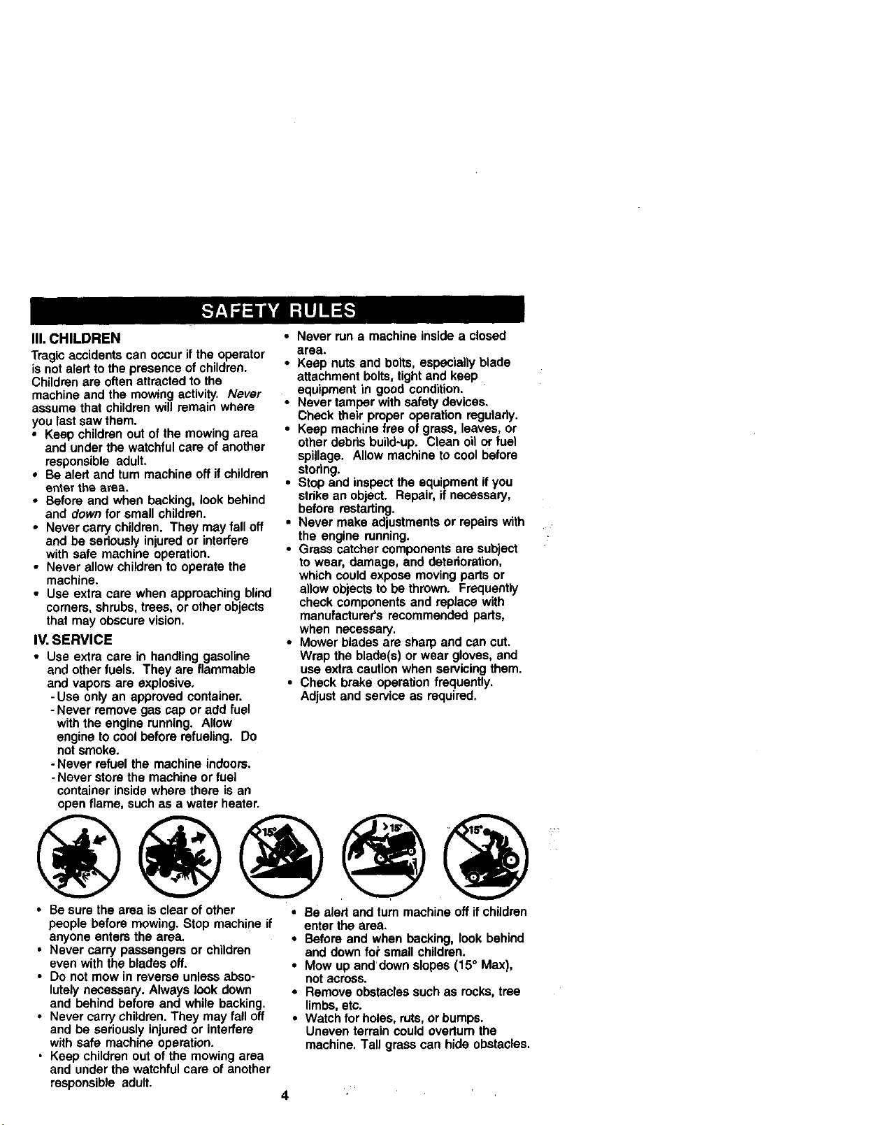
• Be sure the area is clear of other • Be alert and tum machine off if children
people before mowing. Stop machine if
anyone enters the area.
• Never cam/passengers or children
even with the blades off.
• Do not mow in reverse unless abso-
lutely necessary. Always look down
and behind before and while backing.
• Never carry children. They may fall off
and be seriously injured or interfere
with safe machine operation.
. Keep children out of the mowing area
and under the watchful care of another
responsible adult.
enter the area.
• Before and when backing, look behind
and down fopsmall children.
• Mow up and dowa slopes (15° Max),
not across.
• Remove obstacles such as rocks, tree
limbs, etc.
• Watch for holes, ruts, or bumps.
Uneven terrain could overturn the
machine, Tall grass can hide obstacles.
.
Page 5
• Use slow speed. Choose a low gear so
that you will not have to stop or shift
while on the slope.
• Avoid starting or stopping on a slope, if
tires lose traction, disengage the blades
and proceed slowly straight down the
slope.
• If machine stops while going uphill,
disengage blades, shift into reverse
and back down slowly.
• Do not turn on slopes unless neces-
sary, and then, turn slowly and gradu-
ally downhill, if possible.
_.Look for this symbol to point out
important safety precautions, it means
CAUTION!!! BECOMEALERT!!! YOUR
SAFETY IS INVOLVED.
A_. CAUTION: In order to prevent
accidental starting when setting up,
transporting, adjusting or making repairs,
always disconnect spark plug wire and
place wire where it cannot contact spark
plug.
CAUTION: Do not coast down a hill
in neutral, you may' lose control of the
tractor.
_L CAUTION: Tow only the attachments
that are recommended by and comply
with specifications of the manufacturer of
your tractor. Use common sense when
towing. Operate only at the lowest
possible speed when on a slope. Too
heavy of a load, while on a slope, is
dangerous. Tires can lose traction with
the ground and cause you to lose control
ofyour tractor.
_LWARN!NG: Engine exhaust, some of
its constituents, and certain vehicle
component_ contain or emit chemicals
known to the State of California to cause
cancer and birth defects or other repro-
ductive h_lrm.
_.WARNING: Battery posts, terminals
and related accessories contain lead and
lead compounds, chemicals known to the
State of California to cause cancer and
birth defects or other reproductive harm.
Wash hands after handling.
5
Page 6
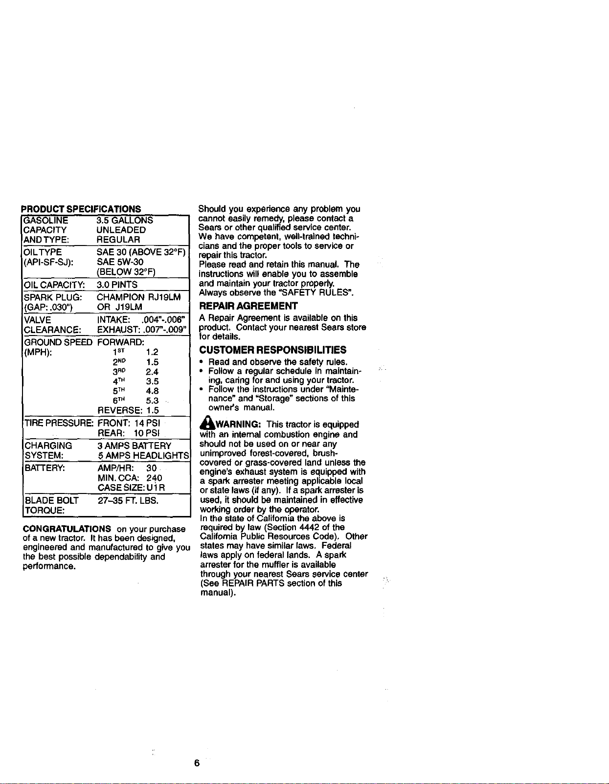
PRODUCT SPECIFICATIONS
GASOLINE 3.5 GALLONS
CAPACITY UNLEADED
ANDTYPE: REGULAR
OILTYPE SAE 30 (ABOVE 32°F
(API-SF-SJ): SAE 5W-30
(BELOW 32°F)
)IL CAPACITY: 3.0 PINTS
;PARK PLUG: CHAMPION RJ19LM
SAP: .030") OR J19LM
VALVE INTAKE: .004"-.006"
CLEARANCE: EXHAUST: .007"-.009"
3ROUND SPEED FORWARD:
IMPH): 1sT 1.2
2N_ 1.5
3RO 2.4
4TM 3.5
5TM 4.8
6TM 5.3
REVERSE: 1.5
TIRE PRESSURE: FRONT: 14 PSI
REAR: 10 PSI
CHARGING 3 AMPS BATTERY
SYSTEM: 5 AMPS HEADLIGHTS
BATTERY: AMP/HR: 30
MIN. CCA: 240
CASE SIZE: U'l R
BLADE BOLT 27--35 FT. LBS,
TORQUE:
CONGRATULATIONS on your pumhase
of a new tractor. It has been designed,
engineered and manufactured to give you
the best possible dependability and
performance.
Shouldyou experienceany problemyou
cannoteasilyremedy,please contacta
Searsor otherqualifiedservicecenter.
We have competent,well-trainedtechni-
clansand the propertoolsto serviceor
repairthistractor.
Please readand retainthis manual. The
instructionswillenable you to assemble
and maintainyourtractorproperly.
Alwaysobservethe "SAFETY RULES".
REPAIR AGREEMENT
A RepairAgreementis availableon this
product, ContactyournearestSearsstore
for details.
CUSTOMER RESPONSIBILITIES
• Read and observethe safetyrules.
• Followa regular schedulein maintain-
ing,caringfor and usingyourtractor.
• Followthe instructionsunder"Mainte-
nance"and"Storage"sectionsofthis
owner's manual.
WARNING: Thistractorisequipped
withan internalcombustionengineand
shouldnotbe usedon or near any
unimprovedforest-covered,brush-
coveredor grass-coveredland unlessthe
engine'sexhaustsystemis equippedwith
a spark arrestermeeting applicablelocal
orstatelaws(if any). Ifa sparkarresteris
used, it shouldbe maintainedineffective
workingorderby theoperator.
In the stateof Califomiathe above is
requiredby law (Section4442 of the
CaliforniaPublicResourcesCode), Other
statesmay havesimilarlaws, Federal
laws applyon federal lands. A spark
arresterfor the muffleris available
throughyournearestSears servicecenter
(See REPAIRPARTSsectionofthis
manual).
:?
i TM
6
Page 7
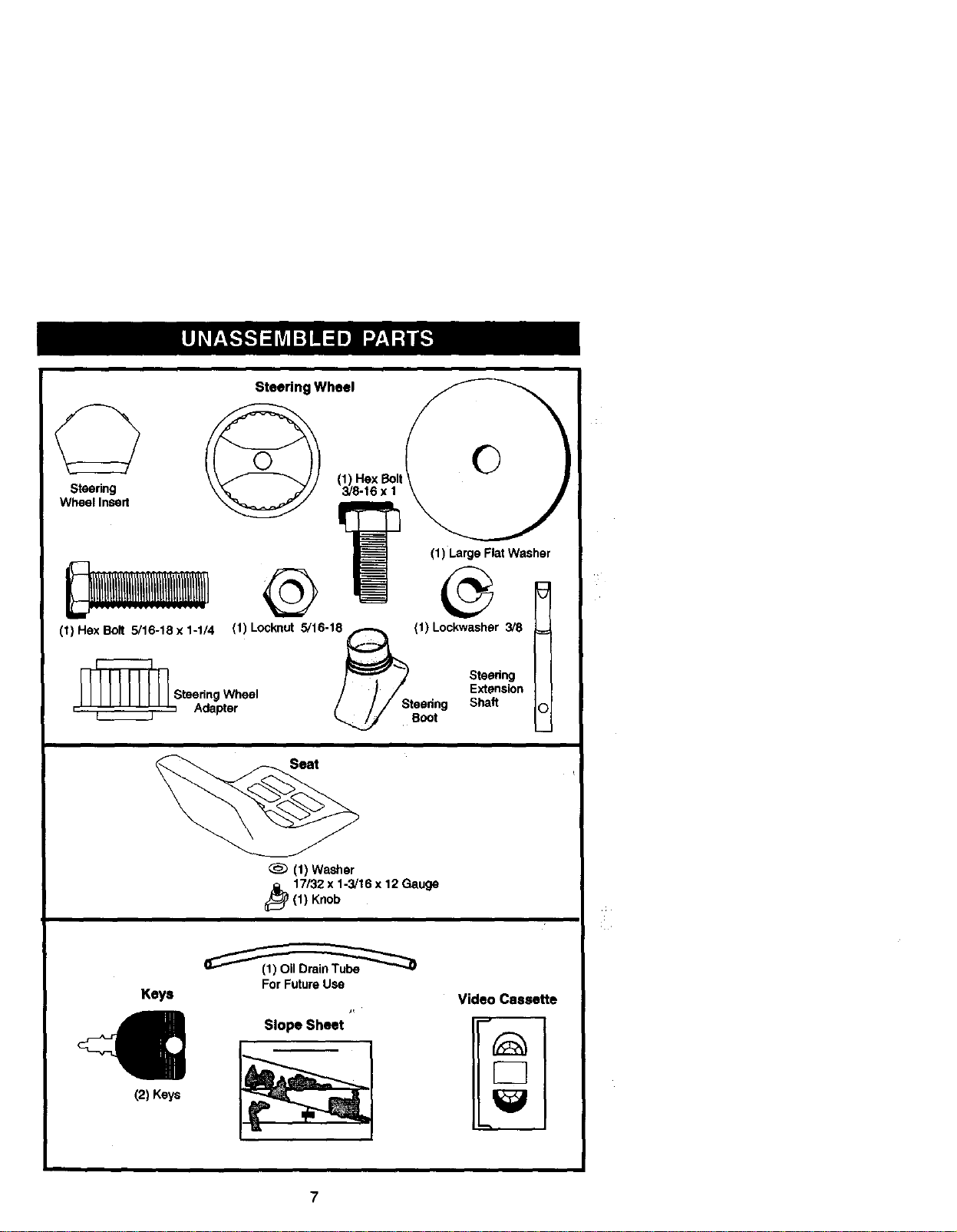
$tsedng
Wheel Insert
Steering Wheel
Flat
(1) Large Washer
(1)HexBolt 5/16-18x1-1/4 (1) Looknut 5/16-18_ (1)Lockwasher 3/8 1
,' ' ' ' ' ' ' ' ' ', Adapter / // Steedng Shaft
Steedng Wheel / / / Extension
(1) Washer
_ 7/32 x 1-3/16 x 12 Gauge
(1) Knob
Keys
For Future Use
Slope Sheet
/ -,,.T_ j Steedng
_ Boot
Video Cassette
€
(2) Keys
Page 8
Your new tractor has been assembled at the factory with exception of those parts left
unassembled for shipping purposes. To ensure safe and proper operation of your
tractor all parts and hardware you assemble must be tightened securely. Use the
correct tools as necessary to insure proper tightness. Review the video cassette before
you begin.
TOOLS REQUIRED FOR ASSEMBLY
A socketwrenchset will makeassembly
easier.Standardwrenchsizesyou need
are listedbelow.
(1) 9/16"wrench (2) 1/2"wrench
(t) Utilityknife (1) Pliers
(1) Tire pressuregauge
When rightor left handis mentionedin
thismanual,it means,from your pointof
view,whenyou are in the operating
position(seatedbehindthe steering
6. Assemble large flat washer, 3/8 lock
washer, 3/8 hex bolt and tighten
securely.
7. Snap steering wheel insert into center
of steering wheel.
8. Remove protective materials from
tractor hoed and grill.
IMPORTANT: Check for and remove any
staples in skid that may puncture tires
where tractor is to roll off skid.
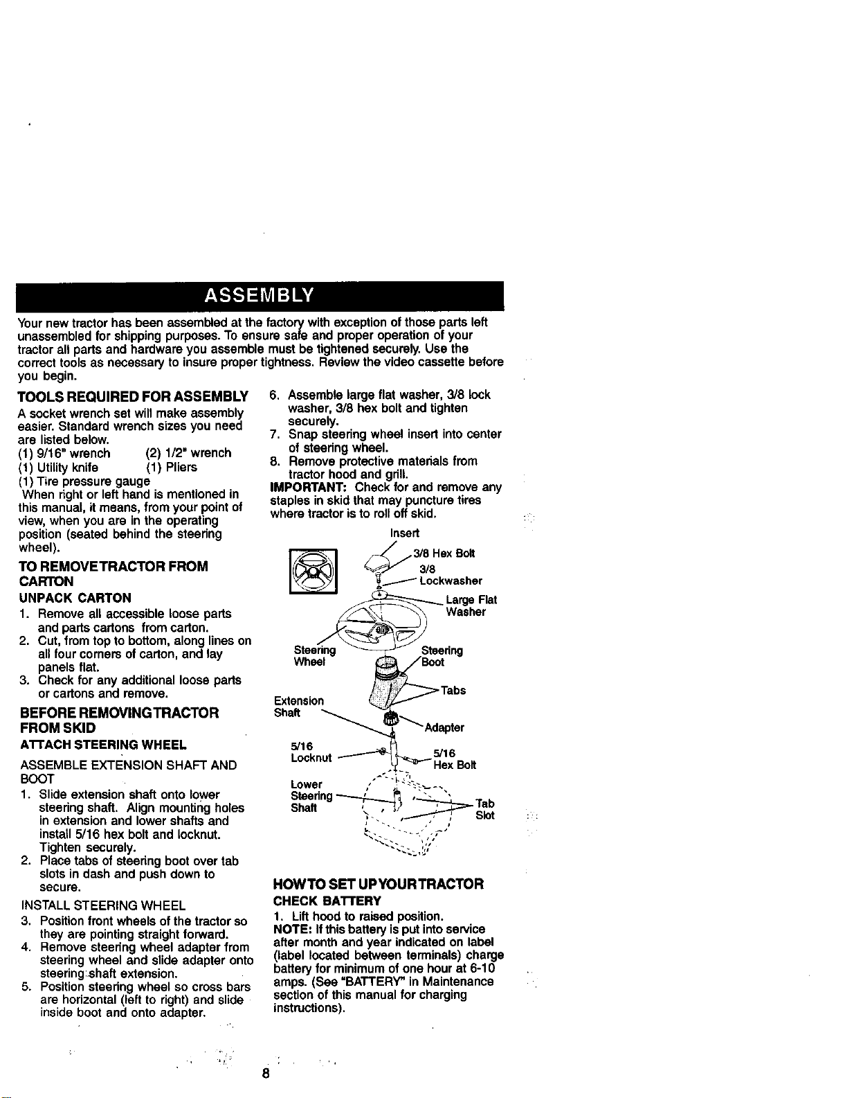
Insert
wheel).
TO REMOVETRACTOR FROM
CARTON
UNPACK CARTON
_,_ Lockwasher
_ Large Flat
1. Remove all accessibleloosepads
and partscartons from carton.
2. Cut, fromtoptobottom,alonglineson
all four cornersof carton,and lay
panelsflat.
3. Check for any additionalloosepads
or cartonsand remove.
BEFORE REMOVINGTRACTOR
FROM SKID
A'I-rACH STEERING WHEEL
ASSEMBLE ExTENsION SHAFT AND
BOOT
1. Slide extension shaft onto lower
steering shaft, Align mounting holes
in extension and lower shafts and
install 5/16 hex bolt and Iocknut.
Tighten securely.
2. Place tabs of steedng boot over tab
slots in dash and push down to
secure.
INSTALL STEERING WHEEL
3, Position front wheels of the tractor so
they are pointing straight forward.
4. Remove steering wheel adapter from
steering wheel and slide adapter onto
steering:shaft extension.
5. Position steering wheel so cross bars
are horizontal (left to right) and slide
inside boot and onto adapter.
Steering _ Steering
Wheel _Boot
Extension I_..,.._(f"/
Locknut _ -
Lower , --_.---._ -.
Steering_ _ ,", ",
Sha.
HOWTO SET UPYOURTRACTOR
CHECK BA'n'ERY
1. Lift hood to raised position.
NOTE: If this battery is put into service
after month and year indicated on label
(label located between terminals) charge
battery for minimum of one hour at 6-10
amps. (See "BATTERY" in Maintenance
section of this manual for charging
instructions).
/:'_:_y _Tabs
Adapter
Hex Bolt
._% __L ,'I
, , Tab
J - • i
8
Page 9
;" -' ' Label
/
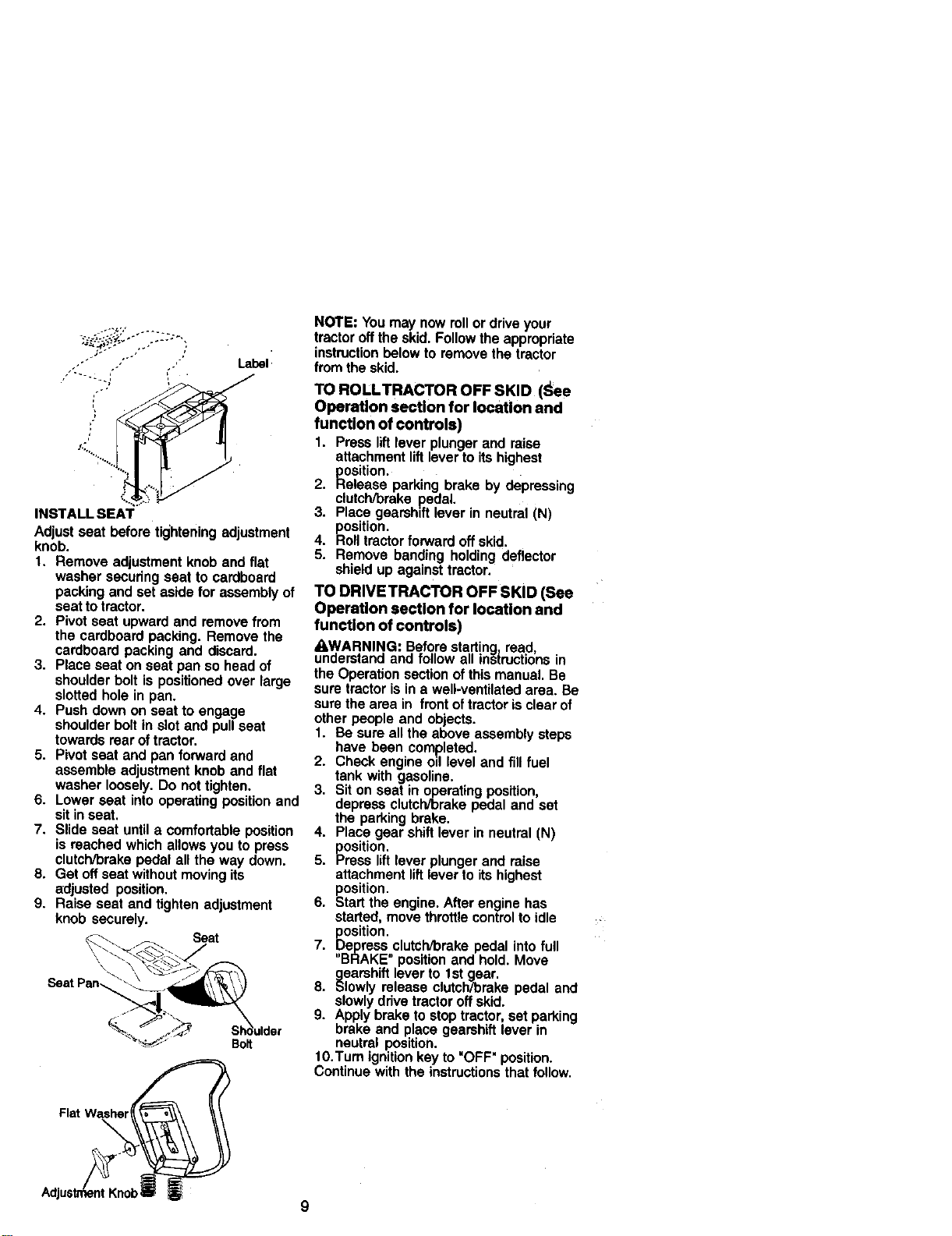
INSTALL SEAT
Adjust seat before tightening adjustment
knob.
1. Remove adjustment knob and flat
washer securing seat to cardboard
packing and set aside for assembly of
seat to tractor.
2. Pivot seat upward and remove from
the cardboard packing. Remove the
cardboard packing and discard.
3. Place seat on seat pan so head of
shoulder bolt is positioned over large
slotted hole in pan.
4. Push down on seat to engage
shoulder bolt in slot and pull seat
towards rear of tractor.
5. Pivot seat and pan forward and
assemble adjustment knob and flat
washer loosely. Do not tighten.
6. Lower seat into operating position and
sit in seat.
7. Slide seat until a comfortable position
is reached which allows you to press
clutch/brake pedal all the way down.
8. Get off seat without moving its
adjusted position.
9. Raise seat and tighten adjustment
knob securely.
Seat
\
Seat Pan_
Bolt
NOTE: Youmay nowrollordriveyour
tractorofftheskid. Followtheappropriate
instructionbelowtoremovethetractor
from theskid.
TO ROLLTRACTOR OFF SKID (_;ee
Operatlon section for location and
funcUon of controls)
I. Press lift lever plunger and raise
attachment lift lever to its highest
position.
2. Release parking brake by depressing
clutch/brake Redal.
3. Place gearshift lever in neutral (N)
position.
4. Roll tractor forward off skid.
5. Remove banding holding deflector
shield up against tractor.
TO DRIVETRACTOR OFF SKID (See
Operation section for location and
function of controls)
AWARNING: Before starting read
understand and fo ow a nstructions n
the Operation section of this manual. Be
sure tractor is in a well-ventilated area. Be
sure the area in front of tractor is clear of
other people and objects.
1. Be sure all the above assembly steps
have been completed.
2. Check engine oil level and fill fuel
tank with gasoline.
3. Sit on seat in operating position,
depress clutch/brake pedal and set
the parking brake.
4. Place gear shift lever in neutral (N)
position.
5. Press lift lever plunger and raise
attachment lift lever to its highest
position.
6. Start the engine. After engine has
started, move throttle control to idle
position.
7. Depress,clutch/brake pedal into full
BRAKE position and hold. Move
gearshift lever to 1st gear.
8. Slowly release clutch/brake pedal and
slowly drive tractor off skid.
9. Apply brake to stop tractor, set parking
brake and place gearshift lever in
neutral position.
10.Turn ignition key to 'OFF" position.
Continue with the instructions that follow.
Flat Wa__
Page 10
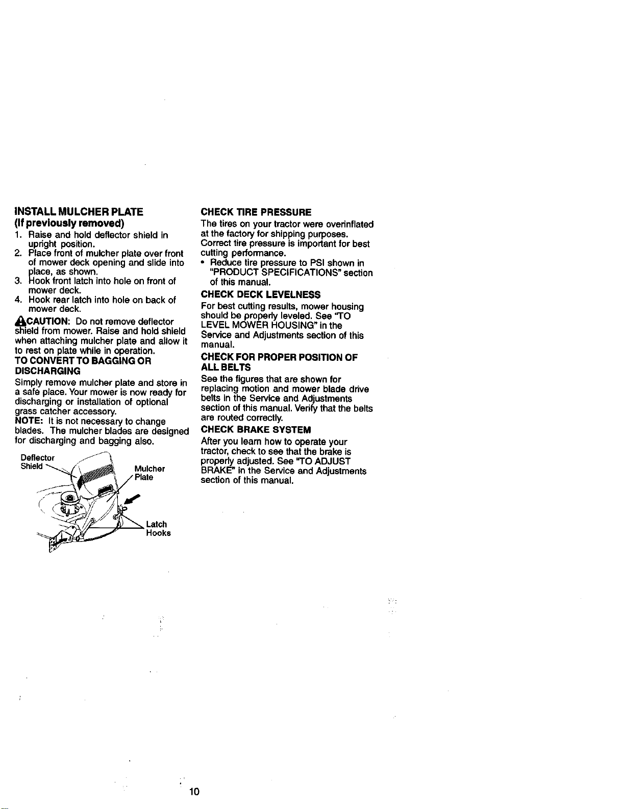
INSTALLMULCHERPLATE
(If previously removed)
1. Raise and hold deflector shield in
upright position.
2. Place front of mulcher plate over front
of mower deck opening and slide into
place, as shown.
3. Hook front latch into hole on frontof
mower deck.
4. Hook rear latch into hole on back of
mower deck.
_CAUTION: Do not remove deflector
shield from mower. Raise and hold shield
when attaching mulcher plate and allow it
to rest on plate while in operation.
TO CONVERT TO BAGGING OR
DISCHARGING
Simply remove mulcher plate and store in
a safe place. Your mower is now ready for
discharging or installation of optional
grass catcher accessory.
NOTE: It is not necessary to change
blades. The mulcher blades are designed
for discharging and bagging also.
Deflector
Mulcher
CHECK TIRE PRESSURE
The tires on your tractor were overinflated
at the factory for shipping purposes.
Correct tire pressure is important for best
cutting performance.
• Reduce tire pressure to PSI shown in
"PRODUCT SPECIFICATIONS" section
of this manual.
CHECK DECK LEVELNESS
For best cutting results, mower housing
should be propedy leveled. See "TO
LEVEL MOWER HOUSING" in the
Service and Adjustments section of this
manual.
CHECK FOR PROPER POSITION OF
ALL BELTS
See the figures that are shown for
replacing motion and mower blade drive
belts in the Service and Adjustments
section ofthis manual. Verify that the belts
are routed correctly.
CHECK BRAKE SYSTEM
After you learn how to operate your
tractor, check to see that the brake is
properly adjusted. See "TO ADJUST
BRAKE" in the Service and Adjustments
section of this manual.
Latch
Hooks
10
Page 11
v'CHECKLIST
Before you operate and enjoy your new
tractor, we wish to assure that you receive
the best performance and satisfaction
from this quality product.
Please review the following checklist:
/ All assembly instructions have been
completed.
,/No remaining loose parts in carton.
,/Battery is properly prepared and
charged.(Minimum 1 hour at 6 amps).
,/Seat is adjusted comfortably and
tightened securely.
/ All tires are propedy inflated. (For
shipping purposes, the tires were
ovednflated at the factory).
,/Be sure mower deck is propedy leveled
side-to-side/front-to-rear for best cutting
results. (Tires must be propedy inflated
for leveling).
,/Check mower and ddve belts. Be sure
they are routed propedy around pulleys
and inside all belt keepers.
,/Check wiring. Bee that all connections
are still secure and wires are propedy
clamped.
While learning how to use your tractor,
pay extra attention to the following
important items:
,/Engine oil is at proper level.
,/Fuel tank is filled with fresh, clean,
regular unleaded gasoline.
,/Become familiar with all controls - their
location and function. Operate them
before you start the engine.
,/Be sure brake system is in safe operat-
ing condition.
11
Page 12
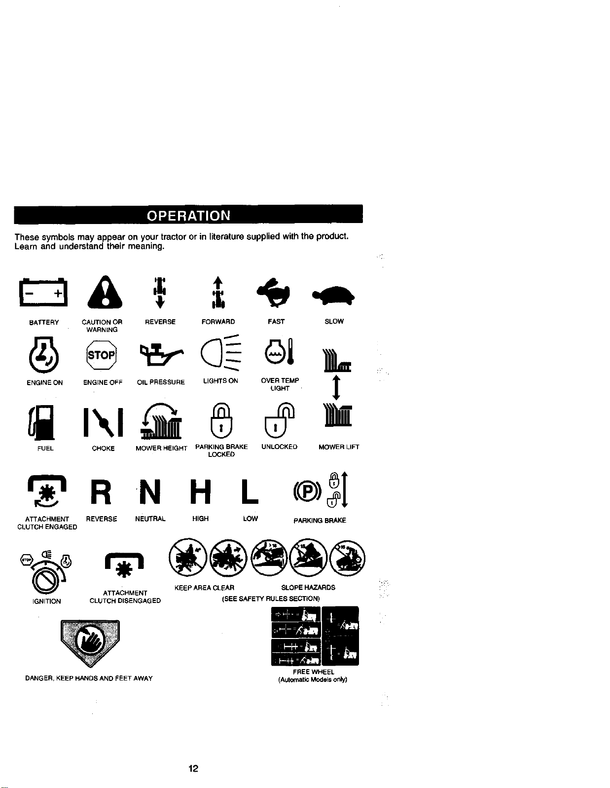
These symbols may appear on your tractor or in literature supplied with the product.
Learn and understand their meaning.
=, I
BATTERY CAUTION OR
WARNING
ENGINE ON ENGINE OFF
FUEL CHOKE
REVERSE FORWARD FAST SLOW
OIL PRESSURE LIGHTS ON OVER TEMP lr
MOWER HEIGHT PARKING BRAKE UNLOCKED MOWER LIFT
LOCKED
LIGHT
A
r_'= R _N H L
ATTACHMENT REVERSE NEUTRAL HIGH LOW PARKING BRAKE
CLUTCH ENGAGED
ATTACHMENT KEEP AREA CLEAR SLOPE HAZARDS i:::
IGNITION CLUTCH DISENGAGED (SEE SAFETY RULES SECTION) :
DANGER, KEEP HANDS AND FEET AWAY
FREE WHEEL
(Automatic Modelsonly)
12
Page 13
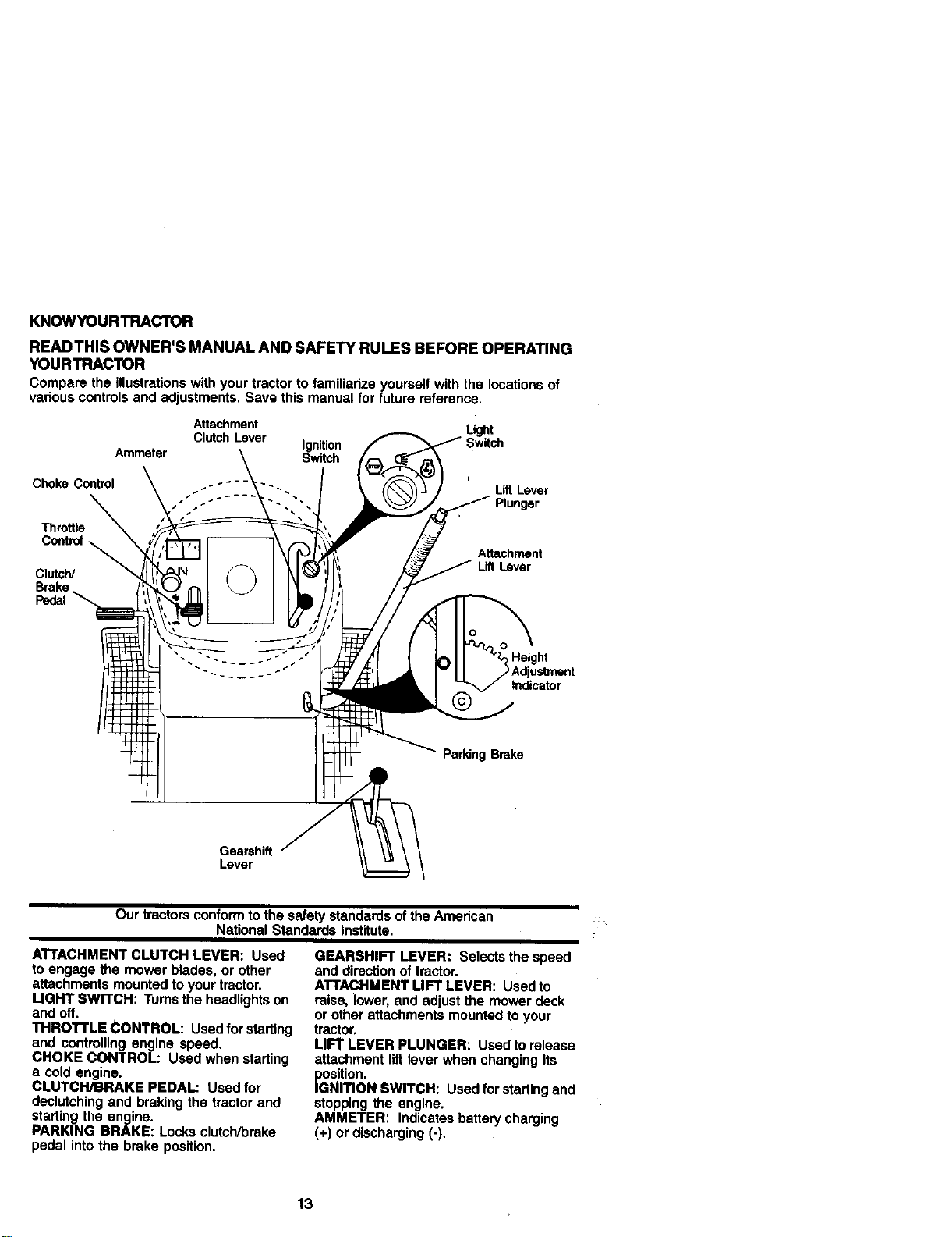
KNOWYOURTRACTOR
READTHIS OWNER'S MANUAL AND SAFETY RULES BEFORE OPERATING
YOURTRACTOR
Comparethe Illustrationswithyourtractortofamiliarizeyourself withthe locationsof
variouscontrolsandadjustments.Save thismanualfor future reference.
Choke Control
Throttle
Control_
Clutch/
Brake
Pedal
Attachment
ClutchLever Ignition
Ammeter Switch
•.-""-" Lift Lever
Light
Plunger
Attachment
LiftLever
,_Height
Adjustment
Indicator
Parking Brake
Gearshift
Lever
Our tractorsconformto thesafetystandardsoftheAmerican
NationalStandardsInstitute.
ATTACHMENT CLUTCH LEVER: Used
to engage the mower blades, or other
attachments mounted to your tractor.
LIGHT SWITCH: Turns the headlights on
and off.
THROTTLE CONTROL: Used for starting
and controlling engine speed.
CHOKE CONTROL: Used when starting
a cold engine.
CLUTCH/BRAKE PEDAL: Used for
declutching and braking the tractor and
starting the engine.
PARKING BRAKE: Locks clutch/brake
pedal into the brake position.
GEARSHIFT LEVER: Selects the speed
and direction of tractor.
ATTACHMENT LIFT LEVER: Used to
raise, lower, and adjust the mower deck
or other attachments mounted to your
tractor.
LIFT LEVER PLUNGER: Used to release
attachment lift lever when changing its
position.
IGNITION SWITCH: Used for startingand
stopping the engine.
AMMETER: Indicates battery charging
(+) or discharging (-).
13
Page 14
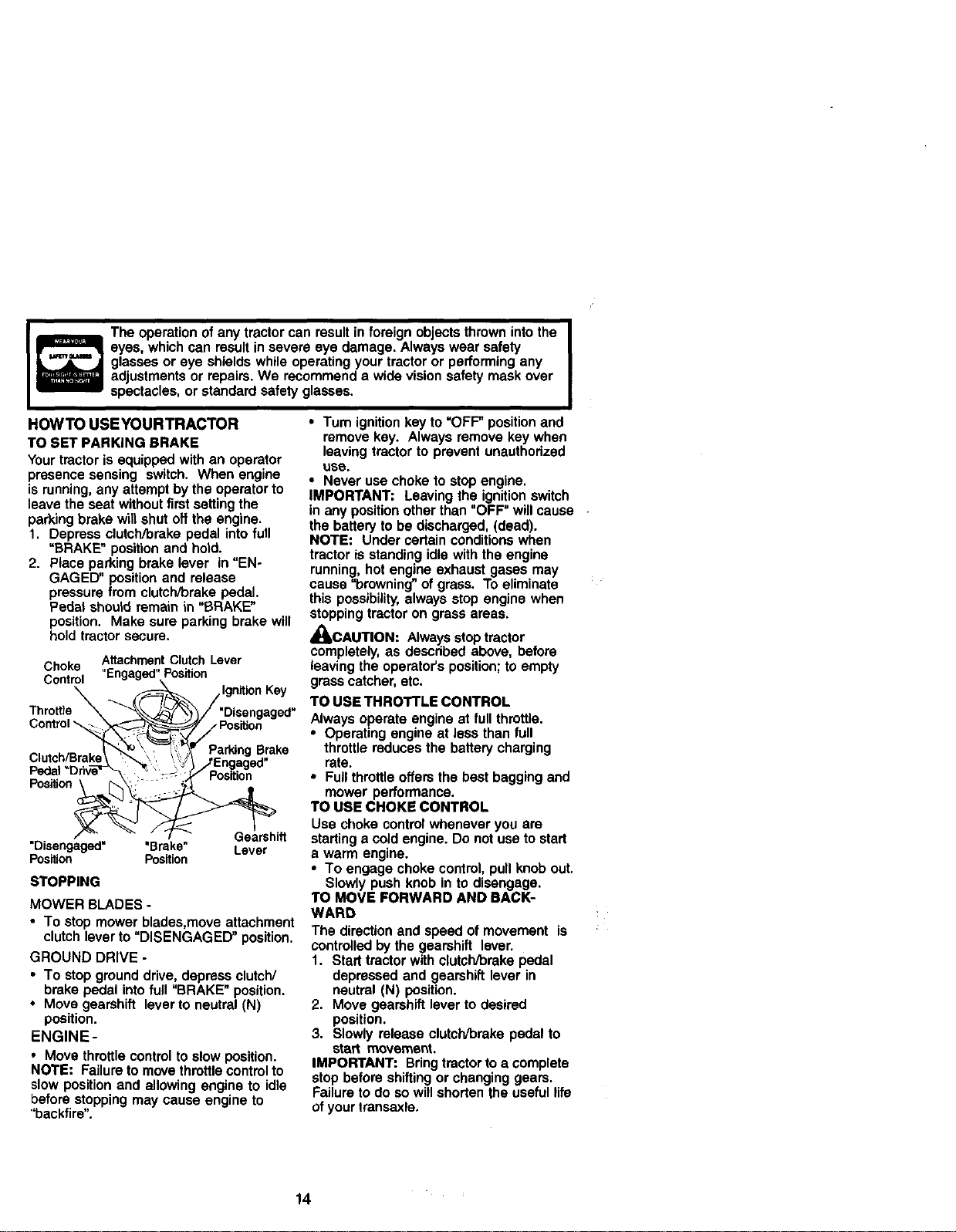
Theoperationofanytractorcanresultinforeign objectsthrownintothe
eyes,whichcan resultinsevere eye damage. Alwayswear safety
glassesor eye shieldswhileoperatingyourtractoror performingany
adjustments or repairs.We recommenda widevisionsafetymaskover
spectacles,orstandardsafetyglasses.
I
HOWTO USE YOUR TRACTOR
TO SET PARKING BRAKE
Your tractor is equipped with an operator
presence sensing switch. When engine
is running, any attempt by the operator to
leave the seat without first setting the
parking brake will shut oft the engine.
1. Depress clutch/brake pedal into full
"BRAKE" position and hold.
2. Place parking brake lever in"EN*
GAGED" position and release
pressure from clutch/brake pedal.
Pedal should remain in "BRAKE"
position. Make sure parking brake will
hold tractor secure.
Choke Attachment Clutch Lever
Control "Engaged" Position
\ -_=_ IgnitionKey
Throttle _ "DisenQa ed"
Control Positio_g
Clutch/Brake\ __\ t/_ ....
,, . _i J=::ngageo
Pedal Di_lve_'-_ \'_> .,(JPositon
Position ._, "
•Disengaged" 'Brake = Lever
Position Position
STOPPING
MOWER BLADES -
• To stop mower blades,move attachment
clutch lever to "DISENGAGED" position.
GROUND DRIVE -
• To stop ground drive, depress clutch/
brake pedal into full "BRAKE" position.
• Move gearshift lever to neutral (N)
position.
ENGINE-
• Move throttle control to slow position.
NOTE: Failure to move throttle control to
slow position and allowing engine to idle
before stopping may cause engine to
"backfire".
" Gearshift
•Tum ignition key to =OFF" position and
remove key. Always remove key when
leaving tractor to prevent unauthorized
use.
• Never use choke to stop engine.
IMPORTANT: Leaving the ignition switch
in any position other than "OFF" will cause
the battery to be discharged, (dead).
NOTE: Under certain conditions when
tractor is standing idle with the engine
running, hot engine exhaust gases may
cause "browning" of grass. To eliminate
this possibility, always stop engine when
stopping tractor on grass areas.
,_CAUTION: Always stop tractor
completely, as descdbed above, before
leaving the operator's position; to empty
grass catcher, etc.
TO USE THROTTLE CONTROL
Always operate engine at full throttle.
• Operating engine at less than full
throttle reduces the battery charging
rate.
• Full throttle offers the best bagging and
mower performance.
TO USE CHOKE CONTROL
Use choke control whenever you are
starting a cold engine. Do not use to start
a warm engine.
• To engage choke control, pull knob out.
Slowly push knob in to disengage.
TO MOVE FORWARD AND BACK-
WARD
The direction and speed of movement is
controlled by the gearshift lever.
I. Start tractor with clutch/brake pedal
depressed and gearshift lever in
neutral (N) position.
2. Move gearshift lever to desired
position.
3. Slowly release clutch/brake pedal to
start movement.
IMPORTANT: Bring tractor to a complete
stop before shifting or changing gears.
Failure to do so will shorten the useful life
of your transaxle.
14
Page 15
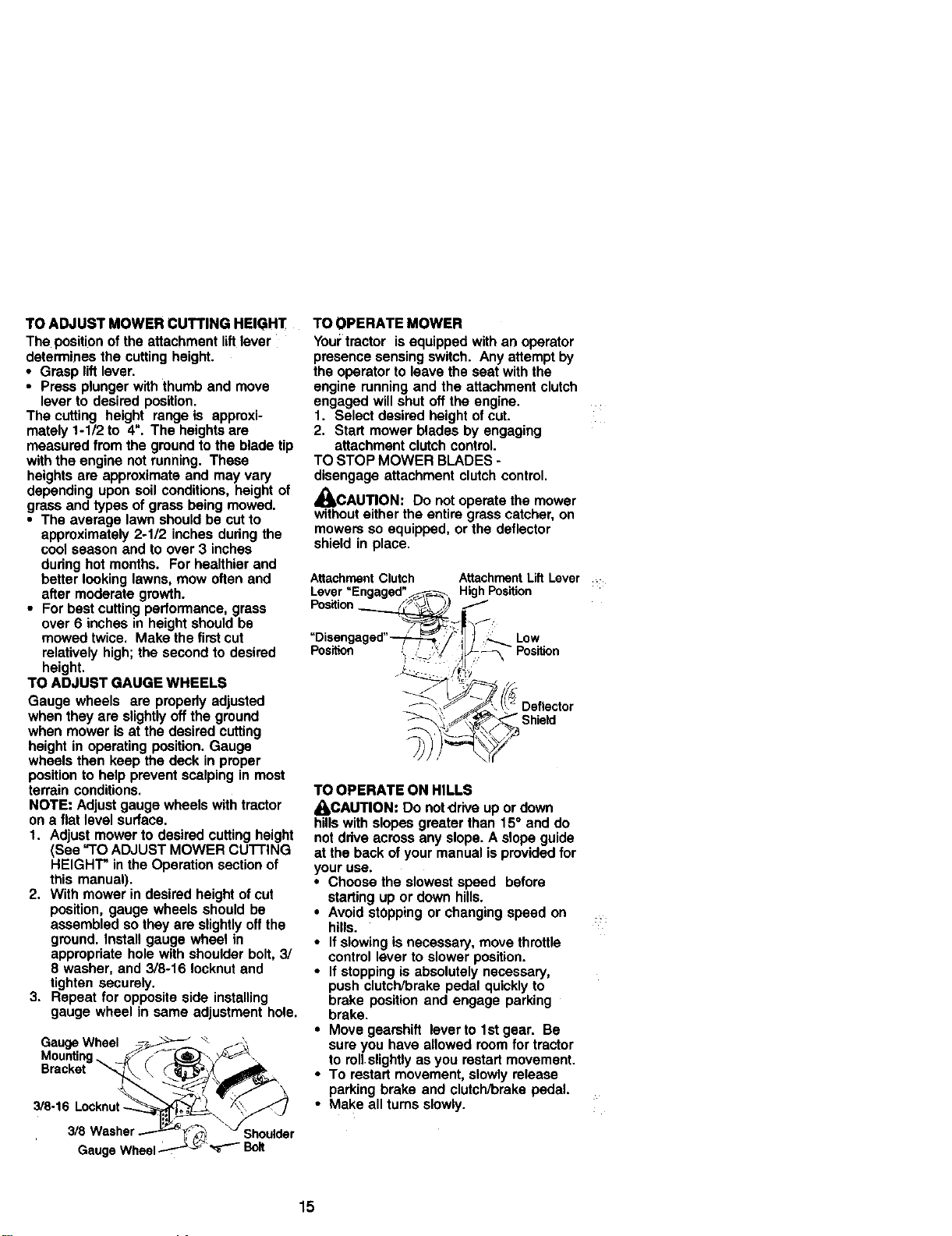
TOADJUST MOWER CUTTING HEIGHT
The position ofthe attachment liftlever
determinesthe cuttingheight.
• Grasp liftlever.
• Pressplungerwiththumband move
leverto desiredposition.
The cutting height rangeis approxi-
mately1-1/2 to 4". The heightsare
measuredfromthe groundtothe bladetip
withthe enginenotrunning. These
heightsare approximateand may vary
dependinguponsoil conditions,heightof
grassand typesof grassbeingmowed.
• The average lawnshouldbe cutto
approximately2-1/2 inches dudngthe
coolseasonand to over 3 inches
duringhot months. Forhealthierand
betterlookinglawns,mow oftenand
aftermoderategrowth.
• Forbest cuttingperformance,grass
over6 inches in heightshouldbe
mowedtwice. Makethe firstcut
relativelyhigh;the secondto desired
height.
TO ADJUST GAUGE WHEELS
Gauge wheels are properlyadjusted
whentheyare slightlyoffthe ground
whenmower isat the desiredcutting
heightin operatingposition.Gauge
wheelsthen keepthe deck inproper
positionto help preventscalpingin most
terrainconditions.
NOTE: Adjustgaugewheelswithtractor
on a flat levelsurface.
1. Adjustmowerto desiredcuttingheight
(Bee"TO ADJUST MOWERcuTrlNG
HEIGHT"inthe Operationsectionof
this manual).
2. With mower in desired height of cut
position, gauge wheels should be
assembled so they are slightlyoffthe
ground. Install gauge wheel in
appropriate hole with shoulderbolt, 3/
8 washer, and 3/8-16 Iocknut and
tighten securely.
3. Repeat for opposite side installing
gauge wheel in same adjustment hole.
GMauntg_inW_l_ _ ..
3/8 16 Locknut /\_ /
," 3/8wk::th_\_r
GaugeWheel.---"_'_'_'_'- Bolt
TO OPERATE MOWER
Your tractor is equipped with an operator
presence sensing switch. Any attempt by
the operator to leave the seat with the
engine running and the attachment clutch
engaged will shut off the engine.
1. Select desired height of cut.
2. Start mower blades by engaging
attachment clutch control.
TO STOP MOWER BLADES -
disengage attachment clutch control,
_bCAUTION: Do not operate the mower
without either the entire grass catcher, on
mowers so equipped, or the deflector
shield in place,
Attachment Clutch
Position
Position Position
TO OPERATE ON HILLS
_kCAUTION: Do notdrive up or down
hills with slopes greater than 15° and do
not drive across any slope. A slope guide
at the back of your manual is provided for
your use.
• Choose the slowest speed before
starting up or down hills.
• Avoid stOpping or changing speed on :::
hills.
• If slowing is necessary, move throttle
control lever to slower position.
• If stopping is absolutely necessary,
push clutch/brake pedal quickly to
brake position and engage parking
brake.
• Move gearshift lever to 1st gear. Be
sure you have allowed room for tractor
to roll slightly as you restart movement.
• To restart movement, slowly release
parking brake and clutch/brake pedal.
• Make all turns slowly.
Attachment LiftLever
High Position
Low
15
Page 16
TO TRANSPORT
• Raise attachment lift to highest position
with attachment lift control.
• When pushing or towing your tractor,
be sure gearshift lever is in neutral (N)
position.
• Do not push or tow tractor at more than
five (5) MPH.
NOTE: To protect hood from damage
when transporting your tractor on a truck
or a trailer, be sure hood is closed and
secured to tractor. Use an appropriate
means of tying hood to tractor (rope, cord,
etc.).
TOWING CARTS AND OTHER ATTACH-
MENTS
Tow only the attachments that are
recommended by and comply with
specifications of the manufacturer of your
tractor. Use common sense when towing.
Too heavy of a load, while on a slope, is
dangerous. Tires can lose traction with
the ground and cause you to lose control
ofyour tractor.
BEFORE STARTINGTHE ENGINE
CHECK ENGINE OIL LEVEL
The engine in your tractor has been
shipped, from the factory, already filled
with summer weight oil
1. Check engine oil with tractor on level
ground.
2. Remove oil fill cap/dipstick and wipe
clean, reinsert the dipstick and screw
cap tight, wait for a few seconds,
remove and read oil level. If neces-
sary, add oil until "FULL" mark on
dipstick is reached. Do not overfill.
• For cold weather operation you should
change oil for easier starting (See "OIL
VISCOSITY CHART" in the Mainte-
nance section of this manual).
• To change engine oil, see the Mainte-
nance section in this manual.
ADD GASOUNE
• Fill fuel tank. Use fresh, clean, regular
unleaded gasoline with a minimum of
87 octane. (Use of leaded gasoline will
increase carbon and lead oxide
deposits and reduce valve life). Do not
mix oil with gasoline. Purchase fuel in
quantities that can be used within 30
days to assure fuel freshness.
IMPORTANT: When operating in tem-
peratures below 32°F(0°C), use fresh,
clean winter grade gasoline to help
insure good cold weather starting.
_kWARNING: Experience indicates that
alcohol blended fuels (called gasohol or
using ethanol or methanol) can attract
moisture which leads to separation and
formation of acids during storage. Acidic
gas can damage the fuel system of an
engine while in storage. To avoid engine
problems, the fuel system should be
emptied before storage of 30 days or
longer. Drain the gas tank, start the
engine and let it run until the fuel lines
and carburetor are empty. Use fresh fuel
next season. See Storage Instructions for
additional information. Never use engine
or carburetor cleaner products in the fuel
tank or permanent damage may occur.
_kCAUTION: Fill to bottom of gas tank
filler neck. Do not overfill. Wipe off any
spilled oilor fuel. Do not store, spill or use
gasoline near an open flame.
16
Page 17
TO START ENGINE
When starlthgthe engineforthe firsttime orif
the engine has runout offuel, itwil take extra
crankingtime to move fuelfrom the tankto the
engine.
1. Sit on seat in operating position,
depress clutch/brake pedal and set
parking brake.
2. Place gear shift lever in neutral (N)
position.
3. Move attachment clutch to =DISEN-
GAGED" position.
4. Move throttle control to fast position
5. Pull choke control out for a cold
engine start attempt. For a warm
engine start attempt the choke contro!
may not be needed.
NOTE: Before starting,read the warm and
coldstartingprocedures below.
6. Insert key into ignition and turn key
clockwise to "START" position and
release key as soon as engine starts.
Do not run starter continuously for
more than fifteen seconds per minute.
Ifthe engine does not start after
several attempts, push choke control
in, wait a few minutes and try again. If
engine still does not start, pull the
choke control out and retry.
WARM WEATHER STARTING (50° F and
above)
7. When engine starts, slowly push
choke control in until the engine
begins to run smoothly. If the engine
starts to run roughly, pull the choke
control out slightly for a few seconds
and then continue to push the control
in slowly.
• The attachments and ground ddve can
now be used, If the engine does not
accept the load, restart the engine and
allow it to warm up for one minute using
the choke as described above.
COLD WEATHER STARTING (50° F and
below)
7. When engine starts, slowly push
choke control in until the engine
begins to run smoothly. Continue to
push the choke control insmall steps
allowing the engine to accept small
changes in speed and load, until the
choke control is fully in. If the engine
starts to run roughly, pull the choke
control out slightly for a few seconds
and then continue to push the control
in slowly. This may require an engine
warm-up pedod from several seconds
to several minutes, depending on the
temperature.
• The attachments can be used dudng
the engine warm-up period and may
require the choke control be pqllsd out
slightly.
NOTE: If at a high altitude (above 3000
feet) or in cold temperatures (below 32 F)
the carburetor fuel mixture may need to
be adjusted for best engine performance.
See "TO ADJUST CARBURETOR" in the
Service and Adjustments section of this
manual.
17
Page 18
MOWINGTIPS
• Mower should be propedy leveled for
best mowing performance. See "TO
LEVEL MOWER HOUSING" in the
Service and Adjustments section of this
manual.
• The left hand side of mower should be
used for trimming.
• Drive so that clippings are discharged
onto the area that has been cut. Have
the cut area to the dght of the machine.
This will result in a more even distribu-
tion of clippings and more uniform
cutting.
• When mowing large areas, start by
turning to the right so that clippings will
discharge away from shrubs, fences,
driveways, etc. After one or two
rounds,
mow in the opposite direction making
left hand tums until finished
• If grass is extremely tall, it should be
mowed twice to reduce load and
possible fire hazard from dried clip-
pings. Make first cut relatively high; the
second to the desired height.
• Do not mow grass when it is wet. Wet
grass will plug mower and leave
undesirable clumps. Allow grass to dry
before mowing.
• Always operate engine at full throttle
when mowing to assure better mowing
performance and proper discharge of
material. Regulate ground speed by
selecting a low enough gear to give the
mower the best cutting performance as
welt as the quality of cut desired.
• When operating attachments, select a
ground speed that will suit the terrain
and give best performance of the
attachment being used.
MULCHING MOWINGTIPS
IMPORTANT: For best performance,
keep mower housing free of built-up grass
and trash. Clean after each use.
• The special mulching blade will recut
the grass clippings many times end
reduce them insize so that as they fall
onto the lawn they will disperse into the
grass and not be noticed. Also, the
mulched grass will biodegmde quickly
to provide nutrients for the lawn.
Always mulch with your highest engine
(blade) speed as this will provide the
best recutting action of the blades.
• Avoid cutting your lawn when it is wet.
Wet grass tends to form clumps and
interferes with the mulching action. The
best time to mow your lawn is the early
afternoon. At this time the grass has
dded and the newly cut area will not be
exposed to the direct sun.
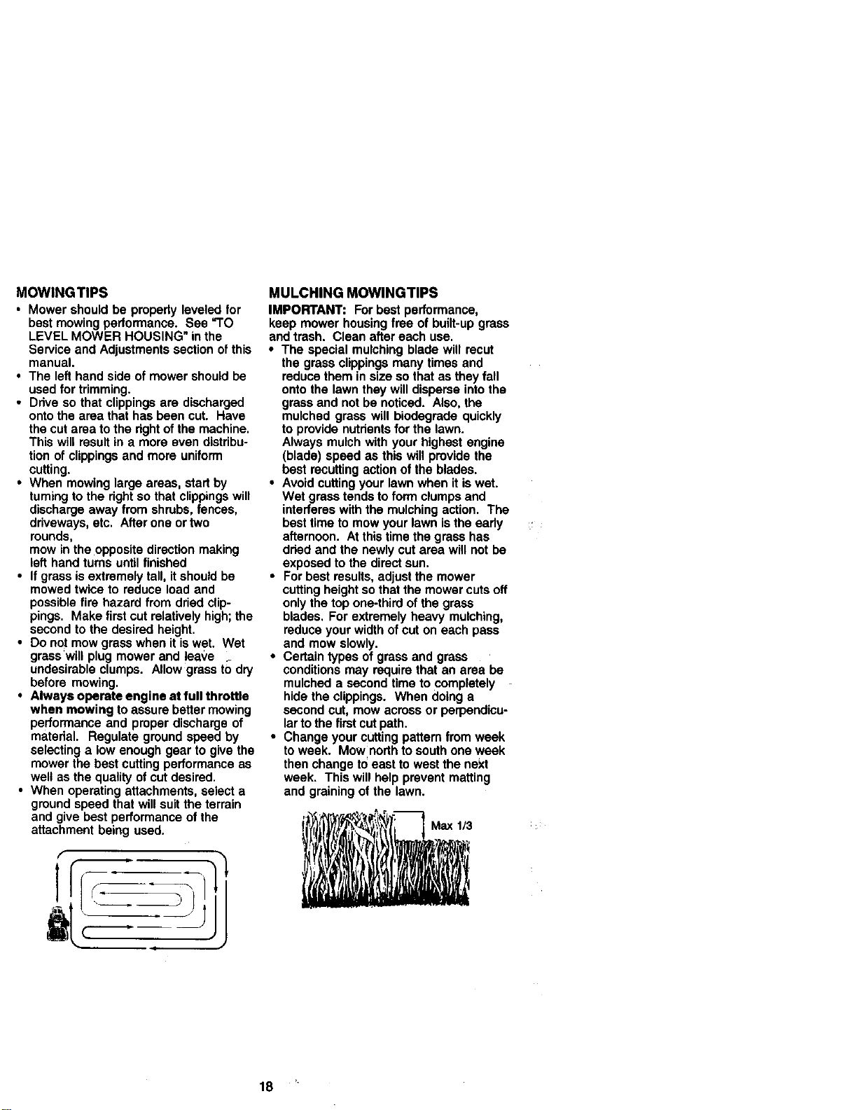
• For best results, adjust the mower
cutting height so that the mower cuts off
only the top one-third of the grass
blades, For extremely heavy mulching,
reduce your width of cut on each pass
and mow slowly.
• Certain types of grass and grass
conditions may require that an area be
mulched a second time to completely
hide the clippings. When doing a
second cut, mow across or perpendicu-
lar to the first cut path.
• Change your cutting pattem from week
to week. Mow north to south one week
then change to east to west the next
week. This will help prevent matting
and graining of the lawn.
i , I t ,
18
Page 19

MAINTENANCESCHEDULE _J_"_'3_ ._j_'_ ._,_ _
REGULARSERVICE _l/'_<_7"_¢tF_.._'_._r'S En VlOE DATES
Chock._o Opera._ l/ l/
ChOck_., Prin.., l/
CheckOp_rato_Presenceand
R c_ _ _ F==_,,,,., V' V'. t/
A SharFen/Rep_ce Mower elede $ _
oT Che_ Batter)' Level
R Cleanaa_ry=r_T_._ls _ I/
(_heck Transe3de Co.rig I_
A_lustBladeee.(s) T_llon II/s
Check Eng_n_Oil Level I_ I_
S Clean Air Filer _=
InspectMu;_er/S_er_Armster II/
Clean Alr Screen _2
Replace OI Filter (If equipped) I1_._
i_ GleanEngineCOolingRn. I_,
Replace A_ Filter Paper Omridge ll_=
Repk_e Fue_FIIt_" _'
GENERAL RECOMMENDATIONS
The warranty on thistractor does not cover
items that have been subjected to operator
abuse or negligence. To receive full value
from the warranty, operator must maintain
trador as instructed in this manual.
Some adjustments will need to be made
periodically to properly maintain your
tractor.
All adjustments in the Service and
Adjustments section of this manual should
be checked at least once each season.
• Once a year you should replace the
spark plug, clean or replace air filter, and
check blades and belts for wear. A new
spark plug and clean air filter assure
proper air-fuel mixture and help your
engine run better and last longer,
BEFORE EACH USE
1. Check engine oil level.
2. Check brake operation.
3. Check tire pressure.
4. Check operator presence and
interlock systems for proper operation.
5. Check for loose fasteners.
LUBRICATION CHART
_) Spindle_ _ Spindle_)
Zerk r_l Ir_l Zerk:
®Froo, Fron,
Wheel / _-_-'_l / L_I _"Wheel V°)
Beadng _-_/ _-_ Bearing
Zsrk F_ ...... / _ Zerk
,;,:-, ,,
: L__L,_-.__J '_ G'_earshft
L _J L_:_ I:'ivots -
_)SAE 30 or 10w30 motor oil
_)General Purpose Grease
_) Refer to Maintenance =ENGINE"
Section
IMPORTANT: Do not oil or grease the
pivot points which have special nylon
bearings. Viscous lubricants will attract
dust and dirt that will shorten the life of the
self-lubricating bearings. If you feel they
must be lubricated, use only a dry, pow-
derad graphite type lubricant sparingly.
19
Page 20

TRACTOR
Always observe safety rules when
performing any maintenance.
BRAKE OPERATION
If tractor requires more than six (6) feet
stopping distance at high speed in
highest gear, then brake must be ad-
justed. (See "TO ADJUST BRAKE" in the
Service and Adjustments section of this
manual).
TIRES
• Maintain proper air pressure in all tires
(See =PRODUCT SPECIFICATIONS"
section of this manual).
• Keep tires free of gasoline, oil, or insect
control chemicals which can harm
rubber.
• Avoid stumps, stones, deep ruts, sharp
objects and other hazards that may
cause tire damage.
NOTE: To seal tire punctures and prevent
flat tires due to slow leaks, tire sealant
may be purchased from your local parts
dealer. Tire sealant also prevents tire dry
rot and corrosion.
OPERATOR PRESENCE SYSTEM
Be sure that operator presence and
interlock systems are working properly. If
your tractor does not function as de-
scribed below, repair the problem
immediately.
• The engine should not start unless the
clutchForeke pedal is fully depressed
and attachment clutch control is in the
disengaged position.
• When the engine is running, any
attempt by the operator to leave the
seat without first setting the parking
brake should shut off the engine.
• When the engine is running and the
attachment clutch is engaged, any
attempt by the operator to leave the
seat should shut off the engine.
• The attachment clutch should never
operate unless the operator is in the
seat.
BLADE CARE
For best results mower blades must be
kept sharp. Replace bent or damaged
blades.
BLADE REMOVAL
1. Raise mower to highest position to
allow access to blades.
2. Remove hex bolt, lock washer and flat
washer securing blade.
3. Install new or resharpened blade with
trailing edge up towards deck as
shown. 20
IMPORTANT: To ensure proper assembly,
center hole in blade must align with star
on mandrel assembly.
4. Reassemble hex bolt, lock washer and
flat washer in exact order as shown.
5. Tighten bolt securely (27-35 Ft. Lbs.
torque).
IMPORTANT: Bladeboltisgrade8 heat
treated.
Mandrel Assembly
Hole
c_-"-Hex Bolt(Grade 8)
*A Grade 8 heattreatedbolt canbe identified
by sixlinesonthe bolt head.
TO SHARPEN BLADE
NOTE: We do not recommend sharpen-
ing blade - but if you do, be sure the blade
is balanced.
Care should be taken to keep the blade
balanced. An unbalanced blade will
cause excessive vibration and eventual
damage to mower and engine.
• The blade can be sharpened with a file
or on a grinding wheel. Do not attempt
to sharpen while on the mower.
• To check blade balance, you will need
a 5/8" diameter steel bolt, pin, or a cone
balancer. (When using a cone bal-
ancer, follow the instructions supplied
with balancer.)
NOTE: Do not use a nail for balancing
blade. The lobes of the center hole may
appear to be centered, but are not.
• Slide blade on to an unthreaded portion
of the steel bolt or pin and hold the bolt
or pin parallel with the ground. If blade
is balanced, it should remain in a
horizontal position. If either end of the
blade moves downward, sharpen the
heavy end until the blade is balanced.
5/8" lade
orPin
Center Hole
Page 21

BATTERY
Yourtractorhasabatterychargingsystem
whichissufficientfor normal usa. How-
ever, periodic charging of the battery with
an automotive charger will extend its life.
• Keep battery and terminals clean.
• Keep battery bolts tight.
• Keep small vent holes open.
• Recharge at 6-10 amperes for 1 hour.
NOTE: The original equipment battery on
your tractor is maintenance free. Do not
attempt to open or remove caps or covers.
Adding or checking level of electrolyte is
not necessary.
TO CLEAN BATTERY AND TERMINALS
Corrosion and dirt on the battery and
terminals can cause the battery to =leak"
power.
1. Remove terminal guard.
2. Disconnect BLACK battery cable first
then RED battery cable and remove
battery from tractor.
3. Rinse the battery with plain water and
dry.
4. Clean terminals and battery cable
ends with wire brush until bright.
5. Coat terminals with grease or petro-
leum jelly.
6. Reinstall battery (See "REPLACING
BA'I-rERY" in the SERVICE AND
ADJUSTMENTS section ofthis
manual).
V-BELTS
Check V-belts for deterioration and wear
after 100 hours of operation and replace
if necessary. The belts are not adjustable.
Replace belts if they begin to slip from
wear;
TRANSAXLE COOLING
Keep transaxle free from build-up of dirt
and chaff which can restrict cooling.
ENGINE
LUBRICATION
Only use high quality detergent oil rated
with API service classification SF-SJ.
Select the oil's SAE viscosity grade
when used above 32°F. Check your
engine oil level more frequently to avoid
possible engine damage from running
low on oil.
Change the oil after avery 25 hours of
operation or at least once a year if the
tractor is not used for 25 hours in one
year.
Check the crankcase oil level before
starting the engine and after each eight
(8) hours of operation. Tighten oil fill cap/
dipstick securely each time you check the
oil level.
TO CHANGE ENGINE OIL
Determine temperature range expected
before oil change. All oil must meet API
service classification SF-SJ.
• Be sure tractor is on level surface.
• Oil will drain more freely when warm.
• Catch oil in a suitable container.
1. Remove oil fill cap/dipstick. Be careful
not to allow dirt to enter the engine
when changing oil.
2. Remove cap from end of drain valve
and install the drain tube onto the
fitting.
3. Unlock drain valve by pushing inward
slightly and turning countemlockwisa.
4. To open, pull out on the drain valve.
5. After oil has drained completely, close
and lock the drain valve by pushing
inward and turning clockwise until the
pin is in the locked position as shown.
6. Remove the drain tube and replace
the cap onto to the end of the drain
valve.
7. Refill engine with oil through oil fill
dipstick tube. Pour slowly. Do not
overfill. For approximate capacity see
"PRODUCT SPECIFICATIONS" ,:
section of this manual.
8. Use gauge on oil fill cap/dipstick for
checking level. Be sure dipstick cap is
tightened securely for accurate
reading. Keep oil at =FULL" line on
dipstick. Oil DrainValve
and _...-""
_ 1 Closed
t:emJ_eratura,acc°rdingto your expected operating _1
NOTE: Although multi-viscosity oils Cap f _ ;.>.-" / j
(5W30, 10W30 etc.) improve starting in
cold weather, these multi-viscosity oils
will result in increased oil consumption 21 DrainTube
,ocked
Page 22

CLEAN AIR SCREEN
Airscreenmust bekeptfree of dirtand
chaffto preventenginedamage from
overheating.Cleanwitha wire brushor
compressedair to removedid and
stubborndriedgum fibers.
ENGINECOOUNG FINS
Removeanydust,dirtoroil from engine
coolingfinsto preventengine damage
fromoverheating.Air guidecoversmust
be removed.Remove sidepanels and
hood(See "TO REMOVE HOOD AND
GRILL ASSEMBLY"inthe Serviceand
Adjustmentssectionofthis manual).
Top Air Guide
Cover _,,
Engine Cooling ""
Fins
NOTE: If very dirty or damaged, replace
cartridge.
4. Reinstall cartridge plate, wing nuts,
precleaner, cover and secure with
knob(s).
IMPORTANT: Petroleum solvents, such as
kerosene, are not to be used to clean the
cartridge. They may cause deterioration of
the cartridge. Do notoil cartridge. Do not
use pressurized air to clean or dry car-
tridge.
Knob
Wing Nut
Foam
Pre-Cleaner
Cover
Cartridge
Cover
(Both
Sides)
AIRFILTER
Yourenginewillnotrunproperlyusinga
dirtyairfilter. Cleanthefoampre-cleaner
afterevery25 hoursofoperationorevery
season. Servicepapercartridgeevery100
hoursofoperationor every season,
whicheveroccursfirst.
Serviceaircleanermoreoftenunderdusty
conditions.
1, Removeknob(s)and cover,
TO SERVICE PRE-CLEANER
2. Slidefoam pre-cleaneroff cartridge.
3. Wash it in liquiddetergentand water.
4. Squeeze itdryin a cleancloth.
5. Saturateit in engineoil. Wrapit in
clean,absorbentclothand squeeze to
removeexcessoil.
NOTE: Ifvery dirtyordamaged, replace
pre-cleaner.
6. Reinstallpre-cleanerover cartridge.
7. Reinstallcoverand secure with
knob(s).
TOSERVICECARTRIDGE
t. Removewing nutsand cartridgeplate.
2. Carefullyremovecartridgeto prevent
debrisfromenteringcarburetor.
3. Clean cartridgeby tappinggently on
flatsurface.
Air Scre_
MUFFLER
Inspect and replace corroded muffler and
spark arrester (if equipped) as it could
create a fire hazard and/or damage.
SPARK PLUGS
Replace spark plugs at the beginning of
each mowing season or after every 100
hours of operation, whichever occurs first.
Spark plug type and gap setting are
shown in "PRODUCT SPECIFICATIONS"
section of this manual.
IN-LINE FUEL FILTER
The fuel filter should be replaced Once
each season. If fuel filter becomes
clogged, obstructing fuel flow to carbure-
tor, replacement is required.
1. With engine cool, remove filter and
plug fuel line sections.
2. Place new fuel filter in position in fuel
line with arrow pointing towards'
carburetor.
3. Be sure there are no fuel line leaks
and clamps are properly positioned.
4. Immediately wipe up any spilled
gasoline.
Clamp
_PFiltsr
22
Page 23

CLEANING
• Clean engine, battery, seat, finish, etc.
of all foreign matter.
• Keep finished surfaces and wheels free
of all gasoline, oil, etc.
• Protect painted surfaces with automo-
tive type wax.
CAUTION: BEFORE PERFORMING ANY SERVICE OR ADJUSTMENTS:
1. Depress clutch/brake pedal fully and set parking brake.
2, Place gearshift lever in neutral (N) position.
3. Place attachment clutch in "DISENGAGED" position.
4. Turn ignition key =OFF" and remove key.
5. Make sure the blades and all moving parts have completely stopped.
6. Disconnect spark plug wire from spark plug and place wire where it cannot
come in contact with plug. •
We do not recommendusinga garden
hoseto cleanyour tractorunlessthe
electricalsystem,muffler,airfilterand
carburetorare coveredtokeep waterout.
Water inengine can resultin a shortened
engine life.
TRACTOR
TO REMOVE MOWER
Mower will be easier to remove from the
right side of tractor.
1. Place attachment clutch in =DISEN-
GAGED" position.
2. Move attachment lift lever forward to
lower mower to its lowest position.
3. Roll belt off engine pulley.
4. Remove small retainer spring, and lift
clutch spring off pulley bolt.
5. Remove large retainer spring, slide
collar off and push housing guide out
of bracket.
6. Disconnect anti-swaybar from chassis
bracket by removing retainer spring.
7. Disconnect suspension arms from
rear deck brackets by removing
retainer springs.
Small Retainer Spring
Clutch E
Retainer Spdng
Anti-Swa'
Collar
Housing
Guide
8. Disconnect front links from deck by
removing retainer springs.
9, Raise lift lever to raise suspension
arms. Slide mower out from under
tractor.
IMPORTANT: If an attachment other than
the mower deck is to be mounted on the
tractor, remove the front links and hook
the clutch spring Into square hole in
frame.
TO INSTALL MOWER
1. Raise attachment lift lever to its
highest position,
2. Slide mower under tractor with
discharge guard to dght side of tractor.
3. Lower lift lever to its lowest position.
4. Install mower in reverse order of
removal instructions.
SuspensionArms ,-J
-;;_'#,;_-/_"_'_- SquareHole
(Both Sides)
Front Link
Large
Spnng
23
Page 24

TO LEVEL MOWER HOUSING
Adjust the mower while tractor is parked
on level ground or driveway. Make sure
tires are properly inflated (See "PRODUCT
SPECIFICATIONS" section of this manual).
If tires are over or underinflated, you will
not properly adjust your mower.
SIDE-TO-SIDE ADJUSTMENT
• Raise mower to its highest position.
• At the midpoint of both sides of mower,
measure height from bottom edge of
mower to ground. Distance "A" on both
sides of mower should be the same or
within 1/4" of each other.
• If adjustment is necessary, make
adjustment on one side of mower only.
• To raise one side of mower, tighten lift
link adjustment nut on that side.
• To lower one side of mower, loosen lift
link adjustment nut on that side.
NOTE: Each full turn of adjustment nut will
change mower height about 1/8".
• Recheck measurements after adjusting.
BottomEdge _ BottomEdge
ofMower to_ !'Ll.,L[_of Mower to
Ground_l (_[ 1_"Odnd
• Beforemaking any necessaryadjust-
ments,checkthat bothfront linksare
equalin length. Bothlinksshouldbe
approximately10-3/8".
• If linksare notequal in length,adjust
one linkto same lengthas otherlink.
• To lowerfrontofmowerloosennut"E"
on bothfront linksan equal numberof
turns.
• When distance_D"is t/8" to 1/2"lower
at frontthanrear, tighten nuts"F"
againsttrunnionon bothfrontfinks.
• To raisefrontof mower,loosen nut up,
fromtrunnion on both frontlinks.
Tightennut=E"on both frontfinksan
equal numberofturns.
• When distance "D" is 1/8"to 1/2" lower
at front than rear,tightennut"F-"against
trunniononbothfront links.
• Recheck side-to-sideadjustment.
Mandrel
% o°
BothFrontLinksShouldbe Equalin Length
Suspension
Ann
Lift Link Adjustment
Nut
FRONT-TO-BACK ADJUSTMENT
IMPORTANT: Deck must be level side-to-
side. If the following front-to-back adjust-
ment is necessary, be sure to adjust both
front links equally so mower will stay
level side-to-side.
To obtain the best cutting results, the
mower housing should be adjusted so
that the front is approximately 1/8" to 1/2"
lower than the rear when the mower is in
its highest position.
Check adjustment on right side of tractor.
,Vleasure distance "D" directly in front and
_ehind the mandrel at bottom edge of
nower housing as shown.
,, _ I Nut "E"
Trunnion
Nut F"_
FrontLinks
TO REPLACE MOWER BLADE DRIVE
BELT
The mower blade ddve belt may be
replaced without tools. Park the tractor on
level surface. Engage parking brake.
BELT REMOVAL -
1. Remove mower from tractor (See "TO
REMOVE MOWER" in this section of
this manual).
2. Work belt off both mandrel pulleys and
idler pulleys.
3. Pull belt away from mower.
24
Page 25

BELT iNSTALLATION -
4. Install new belt in reverse order of
removal.
5. Make sure belt is in all pulley grooves
and inside all belt guides.
6. Install mower in reverse order of
removal instructions.
Mandrel
Pulle_
TO ADJUST BRAKE
Your tractor is equipped with an adjust-
able brake system which is mounted on
the right side of the transaxle.
If tractor requires more than six (6) feet
stopping distance at high speed in
highest gear, then brake must be ad-
justed.
1. Depress clutch/brake pedal and
engage parking brake.
2. Measure distance between brake
operating arm and nut "A" on brake
rod.
3. If distance is other than 1-1/2", loosen
jam nut and tum nut "A" until distance
becomes 1-1/2". Retighten jam nut
against nut "A".
4. Road test tractor for proper stopping
distance as stated above. Readjust if
necessary. Ifstopping distance is still
greater than six (6) feet in highest
gear, further maintenance is neces-
sary. Contact a Sears or other
qualified service center.
• . "Engaged"
IdlerPulleys
_=_ Mu_e_re'
Nut "A"
With Perking Brake
am Nut
TO REPLACE MOTION DRIVE BELT
Parkthe tractoron levelsurface. Engage
parkingbrake. Forassistance,thereisa
belt installationguide decalon bottom
sideofleft footrest.
I. Removemower(See "1"OREMOVE
MOWER" inthis section of this
manual.)
2. Remove belt from stationary idler and
clutching idler.
3. Pull belt slack toward rear of tractor.
Remove belt upwards from transaxle
pulley by deflecting belt keepers.
4. Pull belt toward front of tractor and
remove downwards from around
engine pulley.
5. Install new belt by reversing above
procedure.
Engine
Pulley
Clutching
Idler
Stationary /
Idler
TRANSAXLE GEAR SHIFT LEVER
NEUTRAL ADJUSTMENT
The transaxle should be in neutral When
the gear shift lever is in neutral (N) (lock
gate) position.The adjustment is preset at
the factory; however, if adjustment is
needed, proceed as follows:
1. Make sure transaxle is in neutral (N).
NOTE: When the tractor 'rear wheels move
freely, the transaxle is in neutral.
2. Loosen adjustment bolt in front of the
right rear wheel.
3. Position the gear shift lever in the
neutral (N) position.
4. Tighten adjustment bolt securely.
NOTE: If additional clearance is needed
to get to adjustment bolt, move mower
deck height to the lowest position.
_. _ OperatingArm
25
Page 26

GearshiftLever Neutral
. Bo_t
Lock Gate
Adjustment
TO ADJUST STEERING WHEEL ALIGN-
MENT
If steering wheel crossbars are not
hodzontal (left to dght) when wheels are
positioned straight forward, remove
steedng wheel and reassemble per
instructions in the Assembly section of this
manual.
FRONT WHEEL TOE-IN/CAMBER
The front wheel toe-in and camber are not
adjustable on your tractor. If damage has
occurred to affect the front wheel toe-in or
camber, contact a Sears or other qualified
service center.
TO REMOVE WHEEL FOR REPAIRS
1. Block up axle securely.
2. Remove axle cover, retaining dng and
washers to allow wheel removal (rear
wheel contains a square key - Do not
lose).
3. Repair tire and reassemble.
NOTE: On rear wheels only: align
grooves in rear wheel hub and axle.
Insert square key.
_. Replace washers and snap retaining
ring securely in axle groove.
5. Replace axle cover.
NOTE: To seal tire punctures and prevent
ilat tires due to slow leaks, tire sealant
may be purchased from your local parts
"lealer.Tire sealant also prevents tire dry
"or and corrosion.
TO START ENGINE WITH AWEAK
BATI1ERY
_CAUllON: Lead-acid batteriesgenerate
explosive gases. Keepsparks,flame and
smokingms_edalsaway frombatteries.
Always wear eye protectionwhen around
battedss.
Ifyourbattenjistooweak tostartthe engine,it
shouldbe recharged.(See "BA'I-rERY" in the
MAINTENANCE sectionofthis manual).
If"jumper cables"are usedfor emergency
starting,follow this procedure:
IMPORTANT: Yourtractoris equippedwitha
12 voltnegativegroundedsystem. The other
vehical mustalso be a 12 volt negative
groundedsystem.Do notuseyour tractor
battery to startothervehicles.
TO A'R'ACHJUMPER CABLES -
1. Connect each end of the RED cable to
the POSITIVE (+) terminal of each
battery, taking care not to short
against chassis.
2. Connect one end of the BLACK cable
to the NEGATIVE (-) terminal of fully
charged battery.
3. Connect the other end of the BLACK
cable to good CHASSIS GROUND,
away from fuel tank and battery.
TO REMOVE CABLES, REVERSE ORDER -
1. BLACK cable first from chassis and
then from the fully charged battery.
2. RED cable last from both battedes.
"Positive"(+) "Negative"(-)
Washers
Retaining _ _'_'_
Ring ___ll
Axle Cover _ Square Key
(Rear Wheel Only)
26
Page 27

REPLACING BATTERY
_CAU ,TIO.N: Do notshort battery
terminals oy allowing a wrench or any
other object to contact both terminals at
the same time. Before connecting battery,
remove metal bracelets, wristwatch
bands, rings, etc.
Positive terminal must be connected first
to prevent sparking from accidental
grounding.
1. Lift hood to raised position.
2. Remove terminal guard.
3. Disconnect BLACK battery cable then
RED battery cable and carefully
remove battery from tractor.
4. Install new battery with terminals in
same position as old battery.
5. Reinstall terminal guard.
6. First connect RED battery cable to
positive (+) battery terminal with hex
bolt and keps nut as shown. Tighten
securely.
7. Connect BLACK grounding cable to
negative (-) battery terminal with
remaining hex bolt and keps nut.
Tighten securely
8. Close terminal access doors.
9. Close hood.
Terminal ._i!,_'.......
Access ..
Terminal
Guard Cable
TO REPLACE HEADLIGHT BULB
1. Raise hood.
2. Pull bulb holder out of the hole in the
backside of the grill.
3. Replace bulb in holder and push bulb
holder securely back into the hole in
the backside of the gdll.
4. Close hood.
Hex
Cable
INTERLOCKS AND RELAYS
Looseor damagedwiringmaycauseyour
tractorto runpoorly,stoprunning,or
preventitfromstarting.
• Checkwidng. See electricalwiring
diagraminthe RepairParts section.
TO REPLACE FUSE
Replacewith20 amp automotive-type
plug-infuse. Thefuse holderislocated
behindthe dash.
TO REMOVE HOOD AND GRILL
ASSEMBLY
1. Raise hood.
2. Unsnap headlightwire connector.
3. Standinfront of tractor. Grasphoodat
sides,tilttoward engineand liftoffof
tractor.
4. To replace,reverseabove procedure.
}_. Headlight
/ I Wire Connector
ENGINE
Maintenance, repair, or replacement of
the emission control devices and systems,
which are being done at the customers
expense, may be performed by any non-
road engine repair establishment or
individual, Warranty repairs must be
performed by an authorized engine
manufacturer's service outlet.
TO ADJUST THROTTLE CONTROL
CABLE
The throttle control has been preset at the
factory and adjustment should not be
necessary. Check adjustment as de-
scdbed below before loosening cable. If
adjustment is necessary, proceed as
follows:
1. With engine not running, move throttle
control lever to fast position.
2. Check that swivel is against side of
quarter cimla. If it is not, loosen cable
clamp screw and pull cable back until
swivel is against uarter circle.
Tighten cable clan
Clamp Screw-_
Quarter Cimle;
) screw securely.
27
_Swlvel
tl
Page 28

TO ADJUST CHOKE CONTROL
The choke control has been preset at the
factory and adjustment should not be
necessary. Check adjustment as ds-
scribed below before loosening cable. If
adjustment is necessary, proceed as
follows:
1. With engine not running, move choke
control (located on dash panel) to full
choke position.
2. Remove air cleaner cover, filter and
cartridge plate to expose carburetor
choke (see "AIR FILTER _in the
Maintenance section of this manual).
3. Choke should be closed. If it is not,
loosen casing clamp screw and move
choke cable until choke is completely
closed. Tighten casing clamp screw
securely.
4 Reassemble air cleaner.
Choke Closed
Casing
Clamp. I ;J'_ Choke
Screw _ Lever
TO ADJUST CARBURETOR
The carburetor has been preset at the
factory and adjustment should not be
necessary, However, minor adjustment
may be required to compensate for
differences in fuel, temperature, altitude or
load. If the carburetor does need adjust-
ment, proceed as follows:
In general, turning the mixture screw in
(clockwise) decreases the supply of fuel
to the engine giving a leaner fueVair
mixture. Turning the mixture screw out
(counterclockwise) increases the SUl_Oly
of fuel to the engine giving a dcher fueVair
mixture.
IMPORTANT: Damage to the needles
: and the seats in carburetor may result if
screw is turned in too tight.
PRELIMINARY SETI'ING -
1. Be sure you have a clean air filter, and
the throttle control cable and choke
are adjusted properly (see above).
2. With engine off turn idle mixture screw
in (clockwise) closing it finger tight and
then turn out (counterclockwise) 1-1/4
to 1-1/2 turns.
FINALSETTING -
1. Start engineand allowto warmforfive
minutes, Make finaladjustmentswith
engine runningandshift/motion
controlleverin neutral(N) position.
2. Withthrottlecontrolleverin slow
position,holdthrottlelever againstidle
speedscrew and adjust idlespeed
screwto obtain1200 to 1400 RPM.
3. Whilestill holdingthrottleleveragainst
idlespeed screw, turn idlemixture
screwin (clockwise)untilengine
beginstodie and thenturnout
(counterclockwise)until engine runs
rough. Turnscrew to a pointmidway
betweenthosetwo positions.
4. Continueto holdthrottlelever against
idlespeed screw and adjustidle
speedscrew to obtain900 to 1200
RPM, Release throttlelever.
ACCELERATION TEST -
5. Move throttle control lever from slow to
fast position. If engine hesitates or
dies, turn idle mixture screw out
(counterclockwise) 1/8 turn. Repeat
test and continue to adjust, if neces-
sary, until engine accelerates
smoothly.
High speed stop is factory adjusted. Do
not adjust - damage may result.
IMPORTANT: Never tamper with the
engine governor, which is factory set for
proper engine speed. Overspeeding the
engine above the factory high speed
setting can be dangerous. If you think the
engine-governed high speed needs
adjusting, contacta Seam or o_er qualified
servicecenter, which has proper equip-
ment and expadence to make any
necessary adjustments. ..
Idle Speed
Screw
_ldle Mixture
_Screw
_Thmttle Lever
Idle Speed ..,_'==F==_
Screw __
Throttle _ !die
"._ Mixture
Lever "'crew
28
Page 29

Immediately prepare your tractor for
storage at the end of the season or if the
tractor will not be used for 30 days or
more.
_LCAUTION: Never store thetractor with
gasoline in the tank inside abuilding
where fumes may reach an open flame or
spark. Allow the engine to cool before
stodng in any enclosure.
TRACTOR
Remove mower from tractor for winter
storage. When mower is to be stored for
a period of time, clean it thoroughly,
remove all dirt,grease, leaves, etc. Store
in a clean, dry area.
1. Clean entire tractor (See "CLEANING"
in the Maintenance section of this
manual),
2. Inspect and replace belts, if necessary
(See belt replacement instructions in
the Service and Adjustments section
of this manual).
3. Lubricate as shown in the Mainte-
nance section of this manual.
4. Be sure that all nuts, bolts and screws
are securely fastened. Inspect moving
parts for damage, breakage and wear.
Replace if necessary.
5. Touch up all rusted or chipped paint
surfaces; sand lightly before painting.
BA'I-FERY
• Fully charge the battery for storage.
• After a period of time in storage, battery
may require recharging.
• To help prevent corrosion and power
leakage dudng long psdods of storage,
battery cables should be disconnected
and battery cleaned thoroughly (see
"TO CLEAN BATTERY AND TERMI-
NALS" in the Maintenance section of
this manual).
• After cleaning, leave cables discon-
nected and place cables where they
cannot come in contact with battery
terminals.
• If battery is removed from tractor for
storage, do not store battery directly on
concrete or damp surfaces,
ENGINE
FUEL SYSTEM
IMPORTANT: It is important to prevent
gum depositas from forming in essential
fuel system parts such as carburetor, fuel
hose, or tank dudng storage.
Also, experiance indicates that alcohol
blended fuels (called gasohol or using
ethanol or methanol) can attract moisture
which leads to separation and formation
of acids during storage. Acidic gas can
damage the fuel system of and engine
while in storage.
1. Drain the fuel tank.
2. Start the engine and let it run untilthe
fuel lines and carburetor are empty.
• Never use engine or carburetor cleaner
products'in the fuel tank or permanent
damage may occur.
• Use fresh fuel next season.
NOTE: Fuel stabilizer is an acceptable
alternative in minimizing the formation of
fuel gum deposits during storage. Add
stabilizer to gasoline in fuel tank or
storage container. Always follow the mix
ratio found on stabilizer containeh i Run
engine at least 10 minutes after adding
stabilizer to allow the stabilizer to reach
the carburetor. Do not drain the gas tank
and carburetor if using fuel stabilizer.
ENGINEOIL
Drain oil (with engine warm) and replace
with clean engine oil. (Sea "ENGINE" in
the Maintenance section of this manual).
CYLINDER(S)
!. Remove spark plug(s).
2. Pour one ounce of oilthrough spark
plug hole(s) into cylinder(s).
3. Turn ignition kay to "START" position
for a few seconds to distribute oil.
4. Replace with new spark plug(s).
OTHER
• Do not store gasoline from one season
to another,
• Replace your gasoline can if your can
starts to rust. Rust and/or dirt in your
gasoline will cause problems.
• If possible, store your tractor indoors
and cover it to give protection from dust
ar_ dirt.
• Cover your tractor with a suitable
protective cover that does not retain
moisture. Do not use plastic. Plastic
cannot breathe which allows conden-
sation to form and will cause your
tractor to rust.
IMPORTANT: Never cover tractor while
engine and exhaust areas are still warm,
29
Page 30

:ROUBLESHOOTING CHART
PROBLEM CAUSE CORRECTION
Nill notstart
1. Out offuel.
2. Engine not"CHOKED"
properly.
3. Engine flooded.
4, Bad sparkplug.
5. Dirtyair filter.
6. Dirtyfuel filter.
7 Waterinfuel.
8. Loose or damaged wiring,
9. Carburetor out of adjustment
10.Enginevalves outof
adjustment.
1. Fill fuel tank.
2. See "TO START ENGINE"
in Operation section.
3. Wait several minutes
before attempting to start.
4. Replace spark plug.
5. Clean/replace air filter.
6. Replace fuel filter.
7. Drain fuel tank and
carburetor, refill tank with
fresh gasoline and replace
fuel filter.
B. Check all wiring.
9. See "To Adjust Carburetor"
in Service Adjustments
section.
10.Contact a Sears or other
qualified service center.
Hard to start
Enginewillnot
turn over
Engine clicks but
willnot start
1. Dirtyair filter.
2. Badspark plug.
3, Weak or dead battery.
4. Dirty fuel filter.
5. Stale or dirty fuel.
6. Loose or;damaged wiring.
7. Carburetor out of adjustment.
8.
Engine valves out of
adjustment.
1,
Clutch/brake pedal not
depressed.
2.
Attachment clutch is
engaged.
3.
Weak or dead battery,
4.
Blown fuse.
5.
Corroded battery terminals.
6.
Loose or damaged wiring.
7.
Faulty ignition switch.
8.
Faultysolenoidorstarter.
9.
Faulty operator presence
' switch(as).
1. Weak or dead battery.
2. Corroded battery terminals,
3. Loose or damaged wiring.
4. Faulty solenoid or starter.
1. Clean/replace air filter.
2. Replace spark plug.
3. Recharge or replace
battery.
4. Replace fuel filter.
5. Drain fuel tank and refill
with fresh gasoline.
6. Chsck all widng.
7. See "To Adjust Carburetor"
in Service Adjustments
section.
8. Contact a Sears or other
qualified service center.
1. Depress clutch,'breke
pedal.
2. Disengage attachment
clutch.
i3. Recharge or replace
battery.
4. Replace fuse.
5. Clean battery terminals.
6. Check all wiring.
7. Check/replace ignition
switch.
8. Check/replace solenoid or
starter.
9. Contact a Sears or other
qualified service center.
1. Recharge or replace battery
2. Clean battery terminals.
3. Check all wiring.
4. Check/replace solenoid or
starter.
3O
Page 31

TROUBLESHOOTING CHART
PROBLEM CAUSE CORRECTION
Loss of power
1. Cutting too much graas/too
fast.
2. Throttle in "CHOKE"
position.
3. Build-up of grass, leaves
and trash under mower.
4. Dirty air filter.
5. Low oil level/dirty oil.
6. Faulty spark plug.
7. Dirty fuel filter.
8. Stale or dirty fuel.
9. Water in fuel.
10.Spark plug wire loose.
11 .Dirty engine air screen/fins.
12. Dirty/clogged muffler.
13.Loose or damaged wiring.
14.Carburetor out of
adjustment.
15.Enginevalves outof
adjustment.
1. Set in =Higher Cut" position/
reduce speed.
2. Adjust throttle control.
3. Clean underside of mower
housing.
4. Clean/replace air filter.
5. Check oil level/change oil.
6. Clean and regap or change
spark plug.
7. Replace fuel filter.
8. Drain fuel tank and refill with
fresh gasoline.
9. Drain fuel tank and carbure-
tor, refilltank with fresh
gasoline and replace fuel
filter.
10.Connect and tighten spark
plug wire.
11 .Clean engine air screen/fins
12.Clean/raplece muffler.
13.Chsck all wiring.
14.See "To Adjust Carburetor"
in Service Adjustments
section.
15.Contact a Sears or other
qualified service center.
Excessive
vibration
Engine €ontinues
torun
when operator
leaves seat with
with attachment
clutch engaged
Poorcut-uneven
1. Worn, bent orlooseblade.
2. Bent blade mandrel.
3. Loose/damaged part(s).
1. Faultyoperator-safety
presencecontrolsystem.
1. Worn, bent or loose blade.
2. Mower deck not level.
3. Buildup of grass, leaves,
and trash under mower.
4. Bent blade mandrel.
5. Clogged mower deck vent
holes from buildup of
grass, leaves, and trash
around mandrels.
31 J
1. Replace blade.
Tightenblade bolt.
2. Replace blade mandrel.
3. Tightenloosepart(s).
Replacedamaged pads.
1. Check widng,switches and
connections.If not
contacta Searsor other
qualifiedservicecenter.
1. Replace blade. Tighten
blade bolt.
2. Level mower deck.
3. Clean underside of mower
housing.
4. Replace blade mandrel.
5. Clean around mandrels to
open vent holes.
Page 32

TROUBLESHOOTING CHART
PROBLEM CAUSE CORRECTION
Mower blades will 1. Obstruction in clutch 1. Remove obstruction.
not rotate mechanism.
2. Worn/damaged mower 2. Replace mower drive belt,
drive belt.
3. Frozen idler pulley. 3. Replace idler pulley.
4. Frozen blade mandrel. 4. Replace blade mandrel.
Poor grass 1. Engine speed too slow.
discharge
2. Travelspeed too fast.
3. Wet grass.
4. Mower deck not level,
5. Low/uneven tire air
pressure.
6. Wom, bent or loose blade.
7. Buildup of grass, leaves
and trash under mower.
5. Mower drive belt worn.
g. Blades improperly installed.
10.Improper blades used.
11.Clogged mower deck vent
holes from buildup of grass,
leaves, and trash around
mandrels.
Headlight(s) not
working
(ifso equipped)
1. Switch is"OFP'.
2. Bulb(s) bumed out.
3. Faulty light switch.
4. Loose or damaged wiring.
5. Blownfuse.
Batterywill not
charge
1. Bad battery cell(s).
2. Poor cable connections.
3. Faulty regulator
(if so equipped).
4, Fault/alternator.
Engine "backfires"
whenturning
engine "OFF"
1. Engine throttle control not
set at "SLOW" position
for 30 seconds before
stopping engine.
1. Place throttle control in
"FAST" position.
2. Shift to slower speed.
3. Allow grass to dry before
mowing.
4. Level mower deck.
5. Check tires for proper air
pressure.
6. Replace/sharpen blade.
Tighten blade bolt.
7. Clean underside of mower
housing.
8. Replace mower drive belt.
9. Reinstall blades sharp edge
down.
10.Replace with blades listed
in this manual.
1t.Clean around mandrels to
open vent holes.
1. Turn switch "ON'.
2. Replace bulb(s).
3. Check/replace light switch.
4. Check wiring and connec
tions.
5. Replace fuse.
1. Replace battery.
2. Check/clean all connec
tions.
3. Replace regulator.
4. Replace alternator.
1. Move throttle control to
"SLOW" position and allow
to idle for 30 seconds before
stopping engine.
32
Page 33

SCHEMATIC
TRACTOR - - MODEL NUMBER 917.271830
i
- < x_o ,o]Fo -
A_E. ___s____ ', ', S',_ER
(OPTIONAL) _ ,
i RED
_r_ :©, O-d----_ I "--"'---'
CLUTCH / BRAKE
IGNITION ........ (NOT OCCUPIED
SWITCH ',_ ',
)G A1, (PEDAL
(OPTIONAL) _ SPARK
', FUEL_ UNIT
: LINE I TWI_ CYL ENGINES)
i I
i I _,,_q31_l f_RF.M ou_,_.q" 211VOLTS _._ Mlfl. O _ RpM
FUELSHUT-OFF SOLENOID _ _".........
(IF SOEQUIPPED) [ uemm sy__
I L ......... I
YOUR TRACTOR IS _ BLACK
EQUIPPED WITH A SPECIAL 1
THE LIGHTS ARE NOT
CONNECTED TO THE
ALTERNATOR SYSTEM, L_
BATTERY, BUT HAVE THEIR
OWN ELECTRICAL SOURCE. HEADLIGHTS
BECAUSE OF THIS, THE
BRIGHTNESS OF THE LIGHTS F,
WILL CHANGE WITH ENGINE
SPEED. AT IDLE THE LIGHTS
WILL DIM. AS THE ENGINE IS NON-REMOVABLE
SPEEDED UP, THE LIGHTS CONNECTIONS
WILL BECOME THEIR BRIGHTEST.
iGNITiON SWITCH
WIRING INSULATED CLIPS
NOTE: IF WIRING INSULATED CLIPS WERE REMOVED FOR
SERVICING OF UNIT, THEY SHOULD BE REPLACED TO
PROPERLY SECURE YOUR WIRING+
/ I J _- -- _ -- J,.L
t_,_ IGNITION GAP
(_ PLUG
_AM_O¢ e _RPM (¢*UmOem 6YSTI_ D_C ONNEGTSD)
C4_ANOE
SAMP*Ce=_u DIODE _ !
SEATSWITCH
I (2 PLUGSON
REMOVABLE
CONNECTIONS
T :
33
Page 34

ELECTRICAL
TRACTOR - MODEL N UMBER 917.271830
22
I
i
I
34
Page 35

ELECTRICAL
TRACTOR - MODEL NUMBER 917.271830
KEY PART
NO. NO. DESCRIPTION
1 163465 Battery 12 VOLT 28 AMP
2 74760412 Bolt Hex Hd 1/4.20unc x 3/4
8 7603J Case Battery
10 145211 Bolt, Btr Front 1/4-20 x 7-1/2
11 150109 Holddown Battery Front Mount
12 145769 NUt, Push Nylon Battery Front 1/4
16 153664 Switch, Inted_k Push-In
21 166182 Harness Light Socket (W/4152j)
22 4152J Bolb Light #1156
24 4799J Cable Battery
25 146148 Cable Battery
26 175158 Fuse
27 73510400 Nut Keps Hex 1/4-20 Unc
28 145491 CableGround
29 1213_5X Switch Seat
30 175566 Switch Ign
33 140403 Key Molded Craltsman
40 17{_17 Harness Ign
41 71110408 Bolt B4k, Fin Hex 1/4-20 Unc x 1/2
42 131563 CoverTerminal
43 175141 Solenoid
45 121433X Ammeter Rectangular 6 Amp
52 141940 Protection Wke Loop
55 1749_o08 Screw Thdrol 5/16-18 x 1/2
NOTE: Allcomponentdimensionsgivenin U.S,
Inches1 Inch= 25.4 mm
35
Page 36

TRACTOR - MODEL NUMBER 917.271830
CHASSIS AND ENCLOSURES
28
S8 12
53
74
208
36
Page 37

TRACTOR - MODEl. NUMBER 917.271830
CHASSIS AND ENCLOSURES
KEY PART
NO. NO, DESCRIPTION
1 169830 Chassis Assembly
2 169061
3 17060612 Screw 3/_-16 x 3/4
5 155272 Bwnper HoodJIPash
g 168337X013 Dash
10 STD533710 Bolt, Carriage 3/8-16xl
11 155927 Panel, Dash, L.H.
12 145660 Clip Tlnnennan Gdlle P/L
13 172107X010 Panel, Desh, R.H.
17 144983X558 Hood Assembly
18 126938X Bumper Hood
20 156437 Plate Mtg Battery Fuel Tank
23 124028X Bushing, Snap, Nylon, Fuel Line
25 19131312 Washer 13/32 x 13/16 x 12 Gauge
26 STD541437 Locknut, Hex, wl_l Inesrt 3/8.16 Unc
28 156725)(558 Grille/Lens Asm
29 155217X599 Lens, Gdlle
30 164919X558 Fend/Ftrest
31 139976 Bracket, Fender Support
37 174.905_8 Screw Thdml 5/16-18 x 1/2
38 169834 Pivot Bracket Assembly, L.H.
51 73800400 Nut Lock w/Insert 1/4-20 UNC
52 19091416 Washer 9/32 x 7/8 x 16 Ga.
53 145201 Bracket Gdlle Pickoff LH
54 161464 Screw Hex Wshd 8-18 x 7/8
55 1452G2 Bracket Grille Pickoff RH
57 _7 Bolt, Fin Hex 1/4-20 UNC x .75
58 140547 Air Duct P/L B&S
60 STD533707 Bolt Rdhd Sqnk 3/8-16 UNC x 3/4
64 154798 Dash LOWerSTLT
74 s'rD641437 NutCrownlock 3/8-16UNC
114 158112 Kesper Belt Rear Lh Sfl
115 17060620 Screw 3/8-16x 1-1/4
142 165867 Plate Reinforcement STLT
143 154966 Bracket Sway'oar Chassis
144 1_7 Bracket Pnt Footrest STLT
145 t56524 Rod Pivot ChaSsis/Hood
159 155123)(428 _der
206 1701_5 Bo_tShoulder 5/16-18 TT
207 1767(To08 Screw Thdro_ 5/1&18 x 1/2
208 17670608 Screw Thdrol 3/8-16 x 1/2
211 145212 Nut Hexflange Lock
212 165919 Insert Lens Reflective
- - 5479J Plug Bulton
NOTE:
All component dlmenslor_ given In U. S.
inches I inch = 25.4 mm
37
Page 38

GROUND ORIVE TRACToR-MODELNUMBERgIT.271030
Page 39

TRACTOR - MODEL NUMB ER 917.271830
GROUND DRIVE
KEY PART KEY PART
NO. NO. DESCRIPTION NO. NO. DESCRIPTION
1 ........ Transaxle (See Breakdown) 62 8883R Cover, Pedal
2 146682 Spring, Return, Brake 64 71170764 Boft, Hex 7/16-20 x 4 Grade 5
3 123666X Pulley, Trensaxle 65 STD551143 Washer
4 12000(_8 Ring, Retainer 66 154778 Keeper, Belt, Engine, Foo_-proot
5 t21520X Strap, Torque 70 134683 Guide, Mower Ddve Belt, R.H.
6 17{To(_12 Screw 5/16-t8 x 3/4 72 19132012 Washer 13/32 x 1-1/4 x 12 Ga.
8 165866 Red Shiftar Fender STLT 74 137057 Spacer, Axle
10 STD561210 Pin, Cotter 75 121749X Washer 25F32x1-1/4x16Ga.
11 105701X Washer, Shift Rate 76 STD581075 E-Ring
13 74550412 Bolt 1/4-28 UNF W/Patch Gr. 8 77 123583X Key, Square 2.0 x .1845/.1865
14 10040400 Washer Lock Hvy Helical 78 121748X Washer 25/32 x 1-5/8 x 16 Ga
16 73800500 Nut LoCk Hx W/Ins 5/16-16 79 STD580G25 Key Woedruff
18 STD523710 Bolt Rn Hex 3/8-16UNC x 1 Gr 5 80 145090 Arm, Shift
19 STD541437 Nut 81 165592 Shaft Asm Cross Tapered 650 20
21 106933X Knob 82 165711 Spdng, Tomlon
22 130804 Rod, Brake 83 19171216 Washer 17/32 x 3/4 x 16 Ga.
24 STD541237 Nut 84 166231 Unk Traeeaxle
25 106888X Spring, Brake Red 85 150360 Nut, Nylock
26 STD551037 Washer 89 158391X428 Console, Shlft, STLT
27 STD561210 Rn 90 124346X Nut, Self-Thding, Wsh Hd 1/4
28 145204 Rod, parking Brake 96 STD624_03 Retainer Spring 1"
29 71673 Cap, parking Brake 112 19091210 Washer 9/32 x 3/4 x10 Gauge
30 169592 Bracket, Trensaxle 113 127285X Strap Torque 90 Degrees
32 ST(_23107 Bolt 116 72110610 Boft Rdhd Sqneck 3/8-16 x 1.25
34 155071 Shaft ASSembly, Foot Ped_ 120 739006G0 Nut Lock Fig. 3/8-16
35 120183X Beadng, Nylon 145 7_ Bolt, Hex FIg_d 5/16-16 Gr. 5
36 STD551062 Washer 150 165850 Bushing Belicrank Grd. Drive
37 ST[_671810 Rc41Rn 151 19133210 Washer 13i32x2x10Ga.
38 131494 Pulley, Idler, Rat 156 1660Q2 Washer Sifted 5/1610 x 1.126
39 STD623727 Bolt 158 165589 Bracket Shift Mount
40 4470J Spacer, Split .395x.59 159 165494 HubTaparedRangeShlftLt
41 165838 Keeper, Belt, Idler 161 72140406 Bolt Rdhd Sqnk 1/4-20 x 3/4 Gr.5
42 19131312 Washer 13!32x13/16x12Ga. 162 73680400 NutCrownrockl/4-20Uoc
47 127783 Pulley, Idler, V-Groove, RasVc 163 74780416 Bolt Hex Fin 1/4-20Unc x 1 Gr 5
48 154407 Balicrank Clutch Grnd Dry Stl 164 19091010 Washer 5/8 x .281 x 10 Ga
49 123205X Retainer, Belt 165 165623 Bracket Pivot Lever
50 S'1_523715 Bolt 166 166880 Screw 5/16-18 x 5/8
51 STD541437 NutCrownLock3/6-16UNC 168 165492 BoltShoulder5/16-18x.561
STD541431 NutCrownLock5/16-18UNC 169 165580 RataFastaningLt
53 165710X Link, ClutCh 170 173896 Keeper Belt Transaxle Geer
55 105709X Spdng, ClutchRetum 197 16_613 Nylin_NinerSnap-ln
56 STD523712 BoltRnHex 3/8-16x1-1/4 198 16_593 WasherNyllner
57 130801 V-BeS, Ground Drive 2(_ 72110612 BOlt Can _,SH 3/8-16 x 1-1/2 Gr. 5
59 16.9691 Keeper, Belt, Center Span NOTE: All component dimensions given In U. S.
61 17060612 Screw 3/8-16 x 3/4 inches I Inch = 25.4 mm
Peedees206-545C 63 140186 Pulley, Engine
39
Page 40

STEERING
TRACTOR - MOD EL NUMBER 917.271830
4O
Page 41

STEERING
TRACTOR - MODEL NUMBER 917.271830
KEY PART
NO, NO. DESCRIPTION
1 139768 Steedng Wheet
2 154427 Axle Assembly STMP Dropoed STL
3 169840 Spindle Assembly, L.H.
4 169839 Sptedle Assembly, R.H.
5 1_o6H Bearing, Race, "nlrust, Hardened
6 121748X Washer 25/32 x 1-5/8 x 16 Gauge
7 19272016 Washer 27/32 x 1-1/4 x 16 Gauge
8 12000(_9 Ring, Kltp
9 3366R Beadng, Steerfng Column
10 169832 Draglink
11 $3D551137 Washer, Lock
13 136518 Spacer, Beadng, Axle
15 145212 Nut, Hexflange LOCk
17 156546 Shaft As_Bmb_y, Steering
18 57079 Washer, Thrust .515 x .750 x .033
19 160395 Support, Shaft
22 165857 Screw Hex Wshhd Torx
23 165851 PItf_nan Shaft Assembly
25 154406 Bracket, Steering
26 126847X Bushing, Link, Drag
27 136874 Gear, Sector
28 19131416 Washer 13/32 x 7/8 x 16 Gauge
29 17060612 Screw 3/8-16 x 5/4
30 S]_o61210 Pin
3_ 130465 ROd,Tte
36 155099 Bushing, Steering
37 152927 Screw
38 139769 Insert, Steedng Wheel
39 19133812 Washer t3/82 x 2-3/8 x 12 Gauge
40 STD541537 Grlpco Nut
41 100711L Adaptor, Steering Wheel
42 145054X428 Boot, Steering Shaft
43 121749X Washer 25/32 x 1-1/4 x 16 Gauge
44 153720 Extension Shaft Steering LR.LT
46 121232X Cap, Spindle
47 6855M FiRing, Gresse
51 STD541431 Nut Lock Hex w/Ins. 5/16-18 UNC
54 74780520 Belt Fin Hex 5/16-18 UNC x 1-1/4
62 1679_Z Kit Steering Asm Sewtce
63 S'RTo23710 Boft, Fin Hex 3_-16 UNC x 1Gr 5
65 160367 Spacer Axle
66 154404 Bearing Arm Plttman
67 72140618 BOlt RDHD SQNK 3/8-16 x 2-I/4
68 169e27 Axle, Brace
79 19132012 Washar 13/32 x 1-1/4 x 12 Ga
80 74950612 Boft He)( Nylon 3/8-16 x 3/4
82 169835 Bracket Susp Chassis Front
85 133835 Fasl_er Christmas Tree
NOTE: All component dtmenc_one given in U. S.
inches 1 inch = 25.4 mm
41
Page 42

ENGINE
2
I_ 14
TRACTOR - MODEL NUMBER 917.271830
38
81
32 34
13
i
31
39
29
OPTIONAL EQUIPMENT
Spark Arresler
33
42
Page 43

ENGINE
TRACTOR - MODEL NUMBER 917.271830
KEY PART
NO, NO. DESCRIPTION
1 17G547 Conkol, T_rot Paddle
2 17720410 Screw, Hex 311dCut 1/4-20 x 5/8
3 ...... En_ne, B&S, (See Breakdown) No, 461707-0145-E3
4 149723 Muffler Exhaust
5 144_69 Exhaust Asm. Left
6 144068 Exhaust Asm. Rtgt_t
7 138129 ClampTube Double Engine
8 171877 Bolt 5/16-18unc x 3/4 W/Sems
10 145552 Heat Shield Lt
11 STD651125 Washer Lock Hvy. Helical 1/4
12 ST[To22507 Bolt Fin Hex 1/4-20Unc x .75
13 165287 Gasket, Muffler
14 148456 Tube Drain Oil Easy
16 ST[_51237 Washer Lock Ext Tooth 3/8
17 17490624 Screw Thdrol 5/8-16xl -1f2 Tytl
23 169837 Shield, Bm/Dbr Guard
25 145996 ControlChoke
26 73920600 Nut Keps 3_-24 Unf
27 152927 Screw "17 #10-32 x 5 x 3/8 Flange
29 137180 Arrestor, Spark
31 15710_ Tank, Fuel
3_ 161696 CapFuelGuage
33 123487X Clamp, Hose
34 106082X Spacer Pad
37 8543R Line, Fuel
38 148315 Plug, Oil Drain Easy
39 109227X Pad Idler
45 17(X_0612 Serew Hex Wsh3/8-16 x 3/4
81 73510400 Nut Keps Hex 1/4-20 Starte_ Nut
NOTE: AllcomponentdimensionsgiveninU. S.
inches1 inch= 25.4 mm
43
Page 44

TRACTOR- MODELNUMBER917.271830
SEATASSEMBLY
5
21
KEY PART
NO. NO,
1
140123 Seat 3350 Bllv'olkCraftsman
2
14_r_51 Bracket Pnt pivot Seat (blk)
3
71116616 Bolt Fin Hex 3/8-16unc X I
4
19131610 Washer 13/32 X 3/4 X 10 Ga
5
145006 Clip Push In Hlnged
6
STD541437 Nut Hex Lock w/Ins 3/8-I 6 unc
7
124181X Spdng Seat Cprsn 2 250 BIk Zi
8
17000616 Screw 3/8-16 x 1,5 SMGML
9
19131614 Washer 13/32 X 1 X 14 Ga
I0
174894 Pan Pnt Seat (blk)
11
166369 Knob Seat
12
121246X Bracket Pnt Mounting Switch
DESCRIPTION
KEY PART
NO, NO. DESCRIPTION
13 121248X Bushing Snap BIk Nyl 50 Id
14 _!2 Bolt Rdhd Sht Nk 1/4-20x1-1/2
15 134300 Spacer Split 28 X 96 Zinc
16 121250X Spring Cpmn 1 27 BIk Pnt
17 123976X Not Lock 1/4 Lge Ffg Gr 5 2_nc
21 171852 Bott ShoukJer 5/16-18 UnC-2A
22 STD541431 NOt Hex Lock w/In,s 5/16-18
24 19171912 Washer 17/32 X 1-3/16 X 12 Ga,
25 127018X Bo_tShoulder 5/16-18 X 62
NOTE: All component dimensions _ven In U. S,
inches 1 Inch = 25.4 mrn
44
Page 45

DECALS
TRACTOR - MODEL NUMBER 917.271830
9
KEY PART
NO, NO.
1 156439
2 176682
3 1716_6
4 171697
5 177253
6 133644
7 177289
8 171808
9 163_O4
11 156368
4
8 7
\
7 13
DESCRIPTION NO. NO. DESCRIPTION
Oecal, Fender Danger Sears 13 146046 Decal, V-Belt Dr Sch Tractor
Decal, Engine 15 160Q96 Decal, Mower Ddve Schematic
Decal, Hood, R.H. 19 138047 Decal, Battery Diehard Sears
Decal, Hood, L,H. 20 172331 Decal, Dec_ Senrs
Deck, Hood Side 22 149516 Denal, Battery
Decal, Maintenance -- 138311 Decal, Lift Handle
Decal, Lower Dash -- 165800X428 Ped Foo_n)st LH STLT
Decal, Rplcmnt -- 165799X428 Pad Footrest RH STLT
Decal, Fender, Craftsman Gold - - 177306 Owner's Manual, English
Decal, Fender STLT Oper Inst F_/S - - 177307 Owners Manual, Spanish
KEY PART
WHEELS AND TIRES
KEY PART
NO. NO. DESCRIPTION
1 59192 Valve Cap, Tire
2 65139 Stem, VaNe
3 106222)( Tire, Front
4 59904 Tube, Front Tire
5 1_6732X427 Rim, Front
6 278H Fitting, Grease (FrOnt Wheel Only)
7 9040H Baadng, Flange (Front Wheel
11
8 106108X427 Rim, Rear
9 12206P.X Tim, Rear
10 7152J Tupa, RearTire
11 104757X428 Cap, Axte
NOTE: All component dimensions given In U. S.
Inches 1 inch = 25,4 mm
(Not Provided, Service Item Only)
O_y)
(Not provided, Service Item Oniy)
45
Page 46

LIFTASSEMBLY
TRACTOR - MODE LNUMBER 917.271830
7
13
19 I
32
13
19
3
6
13
2O
15
2O
46
Page 47

LIFTASSEMBLY
TRACTOR- MODEL NUMBER 917.271830
KEY PART
NO. NO. DESCRIPTfON
1 159460 Lift Lever Inner Wire Assembly
2 159471 Shaft Assembly, Lift
3 105767X Pin, Groove
4 120000(_ E-Ring
5 19211621 Washer 21/32 x 1 x 21 Gauge
6 120183X Beadng, Nylon
7 125631X Gdp, Handle, Fluted
8 122365X Button, Plunger, Red
11 139665 Unk, Lift, LH.
12 13_66 Unk, Uft, R.H.
13 STD_4_08 Retainer Spring
15 173288 Link, Front
16 7335(3800 Nut, Hex, Jam 1/2-13 UNC
17 130171 Trunnion
18 73800800 Nut Lock w/Wsh 1/2-13 UNC
19 139868 Arm, Suspension, Rear
20 163552 Retainer Spring
31 169665 Beadng, Pvt, Lift
3_ 735406C0 Nut, CrOwnlock 3/8;24
NOTE: All _ent dimensions given in U. S.
inches I Inch =25.4 mm
47
Page 48

MOWER DECK
34
TRACTOR - MODEL NUMBER 917.271830
J46 J
21
22
25
27
II
413
Page 49

MOWER DECK
TRACTOR - MODEL NUMBER 917.271830
KEY PART KEY PART
NO. NO. DESCRIPTION NO. NO.
1 165892 Mower Deck Assembly, 42` 67 149846
2 STD533107 Bolt 68 144959
3 138017 Bracket Assembly,Sway Bar, 92 STD541437
4 165460 Bracket Sway Bar 38/42" Deck 102 71061010
5 S_4008 RetatnerSpdng 103 19061216
6 13083_ Arm, Suspension, Rear 104 STD551110
8 85C&57 Bblt, Hex 3/8-24x1.25Gr. 8 105 160793
9 STD551137 washer, Lcck 106 2_JJ
10 140296 Washer, Hardened 111 155197
11 134149 Blade,Mulching 112 155198
13 137645 Shaft Assembly, Mandrel, Vented 113 17060514
14 128774 Housing, Mandrel,Vented 115 72110504
15 110485X Beadng, Ball. Mandrel 116 48_6H
16 140_29 Stripper, Vented Mower Deck 117 165746
18 72140505 Bblt, Cardage 5/16-18x5/8 118 73930600
19 132827 Bolt, Shoulder 119 ST[To61_37
20 159770 Baffle, Vortex 121 143723
2t S'i_541431 NutCrownlock5/16-18UNC 129 19131312
22 134753 Stiffener Bracket 130 STD523710
23 131267 Bracket, Deflector
24 105304X Cap, Sleeve 131 STD533710
25 123713X Spring, Torsion, Deflector 142 165890
26 110452X Nut, Push 143 157109
27 130968X428 Shield, Deflector 144 158634
28 19111016 Washer 11/32xS/8x16Ga. 145 165888
29 131491 Rod, Hinge 146 171977
30 157722 Screw Thdrol Washer Head 147 131335
31 129963 Washer, Spa_er 148 16_(_2
32 153535 Pdlley, Mandrol 149 165898
33 137266 NUt, Toplock, Ranged 150 19091216
34 ST_o33717 Bdlt 151 169670
35 133835 Fastner, Christmas Tree 152 168676
36 131494 Pulley, Idler, Rat 153 169674
37 STD5510G7 Washer 13/82 x13,'16 x16 154 169675
40 STD541437 NutCmwnlock3/8-16UNC 156 169672
44 140(_88 Guard, MaodreL L.H. 157 16_669
45 S_400_ Retainer 158 17720410
46 137729 Screw,'i_d, Rdll 1/4-20x5/8 159 STD533717
48 133944 Washer, Hardened - - 130794
49 174284 Roller Assembly, Cam Foltewer
50 131340 B_t, Sfloulder #10-24 Grade 5 - - 169583
51 STD541410 Locknut
52 139688 Bdlt, Shoulder 5/16-18 UNC
53 131845 Arm Assembly, Pad, Brake
54 133943 Washer, Hardened
55 155046 Am1, Idler
56 165723 Spacer, Retelner
59 141043 Guard, TUV Idler
Front 101 136420
(Includes Key Number 12) 114 $1_541431
Gauge 155 169671
NOTE: All component dimensions given in U. S.
inches ! inch = 25.4 mm
DESCRIPTION
Knob Custom Oval
V-BSh
Nut
Mulcher Cover
Screw Pan HD Phillip 10-24 x 5/8
Washer #10
Washer, Lock
Latch Assembly, Bagger
Nut, Weld
Bracket, Gauge. Wheel L.H.
Bracket, Gauge, Wheel R.H.
Screw 5/16-18
Nut, Hex, KepS 5/16-18 UNC
Bolt, Cardage 5/16 UNC x 1/2
Bolt, Shoulder
Wheel, Gauge
Nut, Centedock 3/8-16
WaSher 3/8 x 7/8 x 14 Gauge
BreCket
Washer 13/32 x 15/16 x 12 Ga.
Bdlt, Fin He)( 3/8-16 UNC x 1
Gr. 5
Bblt, Rdhd Sqnk 3_-16UNC x 1
Arm Spdng Brake Mower
Bracket Arm Idler 42`
Keeper Belt 42" Clutch Cable
Pulley Idler Flat
Bolt Cardege Idler
Spring Extension
Spdng Retum Idler
Retainer Spring Yellow Zinc
Washer 9/32 x 3/4 x 16 Ga.
Bracket Clutch
Cable Clutch 42 In
WaSher Rat 3/8" Type S
Spring Retainer
Spring Retention Lever
Spacer
RodClutch
Screw Hex Tbd Cut 1/4-20 x 5i8
Bolt Rdhd Sqn 3/8-16Unc x 1-3/4
Marrdrel Assembly (Includes Key
Numhers 8-10,12-15,31 and 32.)
MoWer Deck, Complete (Standard
Deck, Order Separately Mulcher
Plate and Gauge Wheel
Components, Key Nos. 101-106
and 111-121)
49
Page 50

TRACTOR-MODELNUMBER917.271830
PEERLESSTRANSAXLE-MODELNUMBER206-545C
I
I
79
5O
Page 51

TRACTOR - MODEL NUMBER 917.271830
PEERLESS TRANSAXLE-MODEL NUMBER 206-54SC
KEY PART KEY PART
NO. NO. DESCRIPTION NO. NO. DESCRIPTION
1 772147
2 780086A
3 770128
4 776395
5 776409
6 778364
6A 778369
7 77833O
8 792180
8A 792O47
9 784352
10 784378
11 778334
12 778309
13 778368
14 778368
15 778370
17 786188
18 78610_
20 792077A
21 792078
22 792O79
25 792073A
25A 792177
26 792125
27 7920Q5
28 788O40
29 780O72
29A 780160
29B 78OO51
29C 780199
30 780106
31 780001
31A 780195
788083
34 780194
35 780193
35A 78O197
36 79OO75
37 7_0C07
38 799O21
Tmnsaxle Cover 39 786G26 Dowel Pin
Needte Bearing 5/6, 40 792076A FlatWasher
Trmmaxle Case .312 ID x ,059W
Countershaft 41A 7S0079 Brake Lever
O*J_ut Shaft 42 792073A Screw 1/4 - 20 x 1-1/4"
Spur Gear (38 teeth) 42A 792065A Screw 1/4 - 20 x 2 114"
Spur Gear (I 5 teeth) 43 792075 Locknut 5 116 - 24
Spur Gear (11 teeth) 44 790025 Brake Pad Holder
Shift Key 45 786066 Spaoer .2625 x 1.0
Woodruff Key #9 46 786066 Brake Lever Bracket
Shift Collar 47 7746_0 Axle (11-15 / 16" Long)
Shift Rod & Fork 48 774691 Axle (16 - 1 / 2_ long)
Bevel Gear (30 teeth) 49 778356 Spur Gear (29 teeth)
Input Bevel Pln_on (13 teeth) 50 778338 Spur Gear (27 teeth)
Bevel Gear (13 teeth) 51 778354 Spur Gear (23 teeth)
(thclude. 14) 52 778352 Spur Gear (19 teeth)
Bevel Pinion (t3 teeth) 53 778350 Spur Gear (16 teeth)
(Include. 13) 54 778346 Spur Gear (15 teeth)
Ring Gear (43 teeth) 56 778355 Spur Gear (11 teeth)
Ddve Pin 57 778337 Spur Gear (13 teeth)
Spacer 1.130 X .695 58 778353 Spur Gear (17 teeth)
Ball 5/16" dia 59 778351 Spur Gear (21 teeth)
Set Screw 3/8 - 16 x 3/6` 60 778349 Spur Gear (24 teeth)
Spring .310 OD x .625 L 61 778345 Spur Gear (25 teeth)
Screw 1/4 - 20 x 1-1/4" 65 780189 Flat Washer
Screw 1/4-20 x 1-5/6` .563 ID x .002W
Retaining Ring (pkg of 2) 66 776422 Input Shaft
ReteJnlngRing 67 T/63_6 Shifter & Brake Shaft
Retalnlng Ring _ 792170 Retaining Ring
ThruSt Washer 70 786187 Spacer .890
.627 ID x .031W 71 788069 SquareCut Ring
Thrust W_aher 71B 788092 "O" Ring
.762 ID'x .031W 76 780090 Rat Washer
Thrust Washer 1.128 ID x .058W
.76_ ID x .031W 77 788078A Inverted Retaining Ring
Anti-Rotation Washer .632 79 792144 Spdng .430 OD x .5000 L
CupWasher 8_ 778333 Bevel & Spur Gear (30 & 13
1.127 ID x .032W teeth)
Rat Washer .750 _Dx .056W 83 778338 Spur Gear (27 teeth)
(Use As Needed) 85 792154 Oil RII Plug
Flat Washer 87 788_89A Oil Seal 9 / 16"
.750 ID x ._W 150 788093A Liquid Gasket RTV snlcone
Oil Seal 5/8" 157 788088A Oil Seal 3/4"
Sushlng .563 180 73(_29A Gear Oil 80wg0
Flanged Bushlng 5 / 6` ID S00 794712 Replacarnent MST
Flanged Bushing .751 L:_6-545C Transaxle
Brake Disk
Brake Pad Plate NOTE: All component dimensions _ven in
Brake Pad (pkg of 2) U.S. inche_ 1 Inch = 25.4 mm
51
Page 52

TRACTOR - MODEL NUMBER 917,271830
BRIGGS& STRATTON ENGINE-MODELNUMBER461707, TYPE NUMBER 0145-E3
1095 VALVE OVERHAUL
GASKET SET
4.
146
52
15 _ TO _rALL. SEEREPAm
lk REQUIRES SPECIAL TOOLS
INSTRUCTION MANUAL.
Page 53

TRACTOR- MODELNUMBER917.271830
BRIGGS&STRATTONENGINE-MODELNUMBER461707,TYPENUMBER0145-E3
865_ 305_
197
447 •
861 PUMP REPAIR KIT
_O 432_ 386
307_,
121 CARBURETOR KIT
432_) 3920104_ 102@
2,_ f
#r REQ_IIRES SPECIAL'rOotS
TO INSTALL. SEE REP_JR
392 432\
391
1036 LABEL KIT-EMISSION I
161
267 %
53
73
t_
33_
934V 7_
1006
78|_
72
Page 54

TRACTOR - MODEL NUMBER 917.271830
BRIGGS& STRA'I'rON ENGINE-MODELNUMBER461707,TYPE NUMBER0145-E3
803
697
Y
797 @
544
801
358 GASKET SET
1.9 gO _TA_ 3®20÷
54
Page 55

TRACTOR - MODEL NUMBE R917.271830
BRIGGS & STRATTON ENGINE-MODEL NUMBER 461707, TYPE NUMBER 0145-E3
KEY PART KEY PART
NO. NO. DESCRIPTION NO, NO, DESCRIPTION
1 498583
2 399265
3 391086
4 493304
5 691162
5A 691163
7 271867
7A 271868
8 495754
9 27803
t0 690334
10A 690366
11 280225
12 273390
271188
271189
13 94565
15 94239
16 690666
19 399264
20 291675
23 491180
24 222698
25 499180
499181
499182
499183
26 499184
499284
499186
499187
27 691299
28 498319
28 498320
29 498314
29 498541
32 691133
33 390420
494553
34 691302
35 65906
36 26826
40 221596
41 292260
42 494553
45 261368
46 691161
47 393415
48 498542
50 213290
51 271412
51A 270884
53 690321
54 93208
73 691438
75 225137
78 691134
91 693483
BCyllnderAssembly
ushing/Seal Kit 95 690718 Screw (Throttle Valve)
• Seal-On 97 693485 Shaft-ThretSe
Surop-Engthe 98 807923 Kit-Idle Speed
Heed-Cylinder #1 102 693509 O Gasket-Carbumetor Body
Head-Cylinder #2 104 693506 _l Pin-FlOat Hinge
Gasket-Cylinder Head #1 106 692078 O Valve-Float Needle
_I Gasket-Cylinder Head #2 107 693482 Body Assembty-Lower
Breather Assembly (Cylinder 108 693505 Valve-Choke
#1)
•1: Gasket.Breather 117 693538 Jet-Main
Screw (Breather Assembly) 693500 Jet-Main (High A_tude)
Screw (Breather Cover) 121 491539 Carburetor Kit
Tube-Breather 122 281411 Spacer
• Gasket-Crankcase (.015' 130 693504 Valve-Thro61e
Thick, Std.)
• Gasket-Crankcase (,005" 133 693512 Float-Carburetor
Thick)
• Gasket-Crenkcase (.009" 147 693508 Jet-Pilot
Thick) 163 271411 * Gasket-Air Cleaner
Screw (Cylinder Head)
Ph_9-OitDrain 177 271170 • Seal-O-Rin
Crankshaft 187 499167 Line-Fuel (_ut to Required
Eushin Length)
• Seat-O_ 197 690364 Screw (Back Plate
Flywheel
Key-Flywheel 203 280997 Crank.Bell
Piston Assembly (Standard) 205 690322 Screw (Bell Crank)
Piston Assembly (.010 "O.S.) 209 691273 Spring-Governor
Piston Assembly (.020" O.S.) 211 261563 Spring-Governor
Piston Assembly (.030" O.S.) 212 693985 Lthk-Thregte
Ring Set, Piston (Standard) 215 690481 Guide-Air
Ring Set, Piston (.010 "O.S.) 219 394348 Gear-Governor
Ring Set, Piston (.020 "O.S.) 220 690412 Washer-Thrust (Governor
Ring Set, Piston (.030 "O.S.) Gear)
Lock-Piston P_n 222 491282 Brecket-Controt
Pin Assembly, Piston (Std.) 227 491297 Lever-Governor
Pin Assembly-Piston (.006" 235 224995 ShiekJ-Fual Spray
OoS')connecting (Standard) 244 230318 Connestor-Hose Pulse Line
Rod-Connecting (.020 U.S.) 258 94930 Screw (Engine Sump)
Screw (Connecting Rod) 267 690316 Screw (Casing Clamp)
Valve-Exhaust(Include(s): 278 691366 Washer (Governor Lever)
Keeper-Valve (Ref. No. 42)) 297 94289 Nut-V_ng (Air Fitter Retainer)
Valve-Intake 304 691390 Screw _131owerHousing)
Spring.Valve (Intake) 305 690960
Spring-Valve (Exhaust) 306 690414 Shletd-Cyitnder
Retainer-Valve (Exhaust) 306A 690435 Shisid-Cylinder
Retainer-Valve (Exhaust)
Keeper-Valve RPM Settings:Low Speed: 1900-2100
Tappet-Valve High Speed: 3000-3200
Camshaft
Stinger-Oil _ Included in Gasket Set, Ref Number 358.
Short Block Included In Carburetor Kit, Ref Number
Manifold-Intake 121.
oO Gasket-Intake $ Included in Value Overhaul Kit, Ref Number
°:_ Gasket-Intake 1095.
Screw (Carburetor) + Included in Fuel Pump Kit, Ref Number 861
Screw (Intake Manifold)
Screen-Rotating NOTE: All component dimensions given in U.S
Washer (Flywheel) inches 1 inch = 25.4 mm
Screw (Flywheel Fan)
Body Assembly-Upper
109 693498 Shaft-Choke
125 693479 Carburetor
146 94196 Key-Tirolng
161 691401 Baas-Air Cleaner
202 690570 Lnk-Mechan ca/ Governor
240 394358 Fliter-Fuet
Housin -Blower
55
Page 56

TRACTOR - MODEL NUMB ER 917.271830
BRIGGS& STRATTON ENGINE-MODELNUMBER461707, TYPE NUMBER 0145-E3
KEY PART KEY PART
NO. NO. DESCRIPTION NO. NO, DESCRIPTION
307 94930 Scraw_Cylinder Shield) 797A 693167 Nut (Starter Terminal)
309 497596 Motor-starter 801 394860 Cap-Ddve
310 690323 Bolt (Starter Motor) 802 497607 Cap-End
311 497608 Brush Set 803 691427 Housing-Starter
332 230674 Nut (Flywheel) 807 693511 Spacer
333 394891 Armature-Magneto 822 693497 Washer-Seal (Throttle Shaft)
334 94731 Screw (Magneto Armature) 847 495715 Oipstick/Tuhe Assembly
337 802592 Plug-Spark
358 495868 Gasket Set 859 693488 O+ Diapgnhram-Fuel Pump
383 89838 Wrench-Spark Plug 861 693502 Ktt-FuelPump
386 693490 0+ Gasket-Pump 865 691196 Cover-Air Guide
391 693487 Body-Pump 865A 691197 Cover-Air Guide
392 693491 0+ Spring-Pump Diaphragm 868 497656 Seal-Valve
404 690442 Washer Governor Crank) 868A 273312 Seal-Valve
423 691100 Screw (Air Cleaner Base 869 261463 Seat-Valve (intake)
425 94823 Screw (Air Cleaner Cover) 870 262924
432 693492 0+ Cap-Spring 871 261961 Bushlng-Gaide (Exhaust)
433 693489 0+ Diaphra_lm-Fuel Pump 231218 Bushing-Guide (Intake)
434 693493 Cover-Diaphragm 877 393456 Wire-Alternator
435 693494 Screw (Diaphragm Cover) 881 495901 Plate-Cover
441 691176 Bracket-OlIFill 918 393815 Hose-Vacuum Cylinder-To-
445 394019 Filter-Air Impulse Pump)(Cut to
447 690297 Screw (Air Guide Cover) Required Length)
449 94882 Screw (Oil Fill Bracket) 934 94627 Screw (Fan Retainer
474 393474 Alternator 955 693513 Plug-Carburetor
482 93621 Screw (Alternator) 968 691207 Cover-Air Cleaner
510 497606 Ddve-Starter 971 690720 Screw (Upper Body To Lower
513 398003 Clutch-Ddve Body)
523 691385 UipsiDistick 1005 498157 Fan-Flywheel
525 690823 Tube-Oil Fill 1006 691247 Retainer-Fan
527 690423 Clamp-Tube 1019 496726 Label Kit
535 272490 Filter-Air 1036 694979 Label Kit-Emission
544 497603 Armature-Starter 1051 263080 Ring-Retaining
552 690553 Bushing (Governor Crank) 1058 273688 Owner's Manual
552A 690552 Bushing (Govemor Crank) 1081 280860 • Seal-O-Ring
562 690311 Bolt.Carriage (Governor 1090 497605 Retainer-Brush
569 272645 • Gasket-Base 1125 691104 Screw (Cover Plate)
572 690415 Cover-Breather (Cylinder #2) 1132 690353 Screw (Oil Slinger)
573 690764 Plate-Back 1136 690329 Screw (Governor, Control
592 92278 Nut (Governor Lever) Rod)
601 95162 Clamp-Hose 1137 690390 Washer (Govemor, Control
615 690328 Retainer (Governor Crank) Rod
615A 690317 Retainer-Governor Shaft 1138 690330 Nut Governor, Control Rod)
616 491530 Crank-Governor ---- 445777-0027-E1 Replacement Engine
634 690657 • Seal-Governor Shaft
634A 271013 Washer-Foam RPM Settings:Low Speed: 1900-2100
635 66538 Boot-Spark Plug High Speed: 3000-3200
637 693510 Washer-Seal
643 496700 Retainer-Air Filter -- Included in Gasket Set, Ref Number 358.
689 690555 Spdng-Friction O Included in Carburetor Kit, Ref Number
697 93585 Screw (Drive Cap) 121.
725 280866 Shield-Heat _ Included in Value Overhaul Kit, Ref,
726 391362 Gear-Rin_ Number 1095.
741 691285 Gear-Timing + Included in Fuel Pump Kit, Ref Number
783 693059 Gear-Starter 861
789 695050 Widn_ Harness
797 94010 Nut (_tarter Terminal) NOTE: All component dimensions glvan in U.S.
Lever) 1095 498047 Gasket Set-Valve Overhaul
851 493880 Terminal-Cable
Seat-Valve (Exhaust)
inches 1 inch = 25.4 mm
56
Page 57

NOTES
Page 58

NOTES
Page 59

SUGGESTED GUIDE FOR SIGHTING SLOPES FOR SAFE OPERATION
ONLY RIDE UPAND DOWN HILL,
J _Q_n.__ _. _u_,
GUIDE _/_8
NOT ACROSS HILL
greater than 15°), never across the face. Make turns gradu- I
I j_ Operate your Tractor up and down the face of slopes (not J
ally to prevent Upping or loss of control. Exercise extreme I
caution when changing direction on slopes. |
I
Page 60

i i ¸¸ m• / _ i_i ;i • W •
Get it fixed, at your home or ours.
For repair of major brand appliances in your own home...
no matter who made it, no matter who sold it!
1-800-4-MY-HOME s. Anytime, day or night
(1-800.-469-4_)
www.sears.com
To bring in products such as vacuums,
lawn equipment and electronics for repair, call for
the location of your nearest Sears Parts & Repair Center.
1-800-488-1222 A_._,,d_o, night
www.sears.com
For the replacement parts, accessories and owner's manuals
that you need to do-it-yourself, call _ars PartsDirsctSM!
1-800-366-PART eam- 11pmCaT,
(1400-366-7278) 7 days a week
www.sears.com/partsdlrect
To purchase or inquire about a Sears Service Agreement:
1-800-827-6655
7 a.m.- 5 p.m. CST, Mon. - Sat.
Para pedir serviciode reparacibna domicitio, AUCanada pour serviceen frane,_ds:
y paraordenar plezas conentrega a demicilio: 1-ST/-LE-FOYERS=
1"888"SU'HOGAR _
(t-888-784-6427)
(1-877-533-6937)
r "n rk/ _ TrademarkofSeam,ROebUCkandCo.
__ Marc=deF_ca deSear=,RoebuckandCo.
177306 12.07.00 RH Prlnted in U.S.A.
 Loading...