

Page 1

Owner's Manual
[CRAFTSMAN'[
16.5 HP
ELECTRIC START
42" MOWER
AUTOMATIC
LAWN TRACTOR
Model No.
917.271643
• Safety
• Assembly
• Operation
• Maintenance
• Repair Parts
CAUTION:
Read and follow all Safety
Rules and Instructions before
operating this equipment.
Sears, Roebuck and Co., Hoffman Estates, I160179
Visit our Craftsman website:www.sears.com/craftsman
Foranswers to your questions
about thisproduct,Call:
1-800-659-5917
Sear= Craftsman Help Line
5 am - 5 pm, Mort - Sat
Page 2
Warranty............................................... 2
Safety Rules ......................................... 3
Product Specifications .......................... 6
Assembly .............................................. 8
Operation ............................................ 11
Maintenance ....................................... 18
LIMITED TWO YEAR WARRANTY ON CRAFTSMAN RIDING EQUIPMENT PARTS
For two (2) years from the date of purchase, if this Craftsman Riding Equipment is
maintained, lubdcatad and tuned up according to the instructions in the owner's
manual, Sears will repair or replace, free of charge, any parts found to be defective in
matadal or workmanship. Warranty service is available free of charge by returning your
Craftsman dding equipment to your nearest Sears Service Center. In-home warranty
service is available but a trip charge will apply. This warranty applies only while this
product is in the United States.
This Warranty does not cover:.
• Expendable items which become worn during normal use, such as blades, spark
plugs, air cleaners, belts and oil filters.
• "lira replacement or repair caused by punctures from outside objects, such as nails,
thorns, stumps, or glass.
• Repairs necessary because of operator abuse, including but not limited to, damage
caused by towing objects beyond the capability of the dding equipment, impacting
objects that bend the frame or crankshaft, or over speeding the engine.
• Repairs necessary because of operator negligence, including but not limited to,
electrical and mechanical damage caused by improper storage, failure to use the
proper grade and amount of engine oil, faiture to keep the deck clear of flammabTe
debris, or the failure to maintain the equipment according to the instructions con-
tained in the owner's manual.
• Engine (fuel system) cleaning or repairs caused by fuel determined to be contami-
nated or oxidized (stale). In general, fuel should be used within thirty (30) days of its
purchase date.
• Riding equipment used for commercial or rental purposes. A product is "used for
commercial purpose" if is used for any purpose other than single family household
dwellings or in usage where profit is made.
Maintenance Schedule ...................... 18
Service and Adjustments .................... 22
Storable ............................................... 29
Troubleshooting ................................. 30
Repair Parts ........................................ 34
Parts Ordering ..................... Back Cover
LIMITED 90 DAYWARRANTY ON BA'I-]'ERY
For ninety (90) days from date of purchase, if any battery included with this dding
equipment proves defective in matedai or workmanship and our testing determines the
battery will not hold a charge, Sears will replace the battery at no charge. Warranty
service is available free of charge by returning your Craftsman dding equipment to
your nearest Sears Service Center. In-home warranty service is available but a tdp
charge will apply. This warranty applies only while this product is inthe United States.
TO LOCATE THE NEAREST SEARS SERVICE CENTER OR TO SCHEDULE IN-HOME
WARRANTY SERVICE, SIMPLY CONTACT SEARS AT 1-800-4-MY-HOME
This Warranty gives you specific legal rights, and you may also have other dghts which
may vary from state to state.
Seam, Roebuck and Co., [3/817 WA, Hoffman Estates, IL 60179
2
Page 3
MPORTANT: This cutting machine is capable of amputating hands and feet and
throwing objects. Failure to observe the tallowing sarsty instructionscould resultin
safious injury or death.
I. GENERAL OPERATION
• Read, understand, and follow all
instructionsin the manual and on the
machine before starting.
• Only allow responsible adults, who are
familiarwith the instructions,to operate
the machine.
• Clear the area of objects such as rocks,
toys, wire, etc., which could be picked
up and thrown by the blade.
• Be sure the area is clear of other people
before mowing. Stop machine if anyone
enters the area.
• Never carry passengers.
• Do not mow in reverse unless absolutely
necessary. Always look down and
behind before and while backing.
• Be aware of the mower discharge
direction and do not point it at anyone.
Do not operate the mower without either
the entire grass catcher or the guard in
place.
• Slow down before turning.
• Never leave a running machine unat-
tended. Alwaysturn off blades, set
parking brake, stop engine, and remove
keys before dismounting.
• Turn off blades when not mowing.
• Stop engine before removinggrass
catcher or unclogging chute.
• Mow only in daylight or good artificial
light.
• Do not operate the machine while under
the influence of alcohol or drugs.
• Watch fortraffic when operating near or
crossing roadways.
• Use extra care when loading or unload-
ing the machine intoa trailer or truck.
• Data indicatesthat operators, age 60
years and above, are involvedin a large
percentage of riding mower-related
injuries. These operators shouldevaluate
their abilityto operate the ridingmower
safely enough to protectthemselves and
othersfrom seriousinjury.
• Keep machine free of grass, leaves or
other debris build-upwhich can touch
hotexhaust / engine partsand bum. Do
notallow the mower deckto plow leaves
or other debris which can cause build-up
to occur. Clean any oil orfuel
spillagebefore operating or storingthe
machine. Allow machineto coolbefore
storage. 3
I1oSLOPE OPERATION
Slopes are a majorfactor related to loss-of-
control and tipover accidents, which can
rasult insevere in ury or death. All slopes
requireextra caution, fyou cannotback up
the slope or if you feel uneasy on it, do not
mow it.
DO:
• Mow up and down slopes, not across.
• Remove obstacles such as rocks, tree
limbs, etc.
• Watch for holes,ruts, or bumps.
Uneven terrain could overturn the
machine. Tall grass can hide ob-
stacles.
• Use slow speed. Choose a low gear
so that you willnot have to stop or shift
while on the slope.
• Follow the manufacturer's recommen-
dations for wheel weights or counter-
weights to improve stability.
• Use extra care with grass catchers or
other attachments. These can change
the stability of the machine.
• Keep all movement on the slopes slow
and gradual. Do not make sudden
changes in speed or direction.
• Avoid startingor stopping on a slope. If
tires lose traction, disengage the
blades and proceed slowly straight
down the slope.
DO NOT:
• Do not tum on slopes unless neces-
sary, and then, rum slowly and gradu-
ally downhill, if possible.
• Do not mow near drop-offs, ditches, or
embankments. The mower could
suddenly turn over if a wheel is over
the edge of a cliffor ditch,or if an edge
caves in.
• Do not mow on wet grass. Reduced
traction could cause sliding.
• Do not try to stabilize the machine by
putting your foot on the ground.
• DOnot use grass catcher on steep
slopes.
Page 4
IILCHILDREN
Tragcaccidentscanoccuriftheoperator
isnotaledtothepresenceofchitdren.
Childrenareoftenattractedtothe
machineandthemowingactivity.Never
assume that chitdren witi remain where
you last sawthem.
• Keep children out of the mowing area
and under the watchtul care of another
responsible adult.
• Be aled and turn machine off if children
enterthe area.
• Before and when backing, look behind
and down for small children.
• Never carry children.They may fail off
and be seriously injured or interfere
with safe machine operation.
• Never arrow chitdren to operate the
machine.
• Use extra care when apprOachingblind
comers, shrubs, trees, or other objects
that may obscure vision.
IV. SERVICE
• Use extra care in handting gasoline
and other fuels. They are flammable
and vapors are explosive.
-Use only an approved container.
-Never remove gas cap or add fuel
with the engine running. Altow
engine to coot before refueling. Do
notsmoke.
-Never refuel the machine indoors.
-Never store the machine or fual
container inside where there is an
open flame, such as a water heater.
• Never run a machine inside a dosed
area.
• Keep nuts and bolts, especially blade
attachment bolts, tightand keep
equipment in good condition.
• Never tamper with safety devices.
Check their proper operalJonregularly,
• Keep machine free of grass, _eaves, or
other debris build-up. Clean oil or fuel
spillage. Allow machine to cool before
stofin9.
• Stop and inspect the equipment if you
strike an object. Repair, if necessary,
before restarting.
• Never make adjustments or repairs
with the engine running.
• Grass catcher components are subiect
to wear, damage, and deterioration,
which could expose moving pads or
allow objects to be thrown. Frequently
check components and replace with
manufaoturer's recommended pads,
when necessary.
• Mower blades are sharp and Gancut.
Wrap the blade(s) or wear gloves, and
use extra caution when servicing them.
• Check brake operation frequently.
Adjust and service as required.
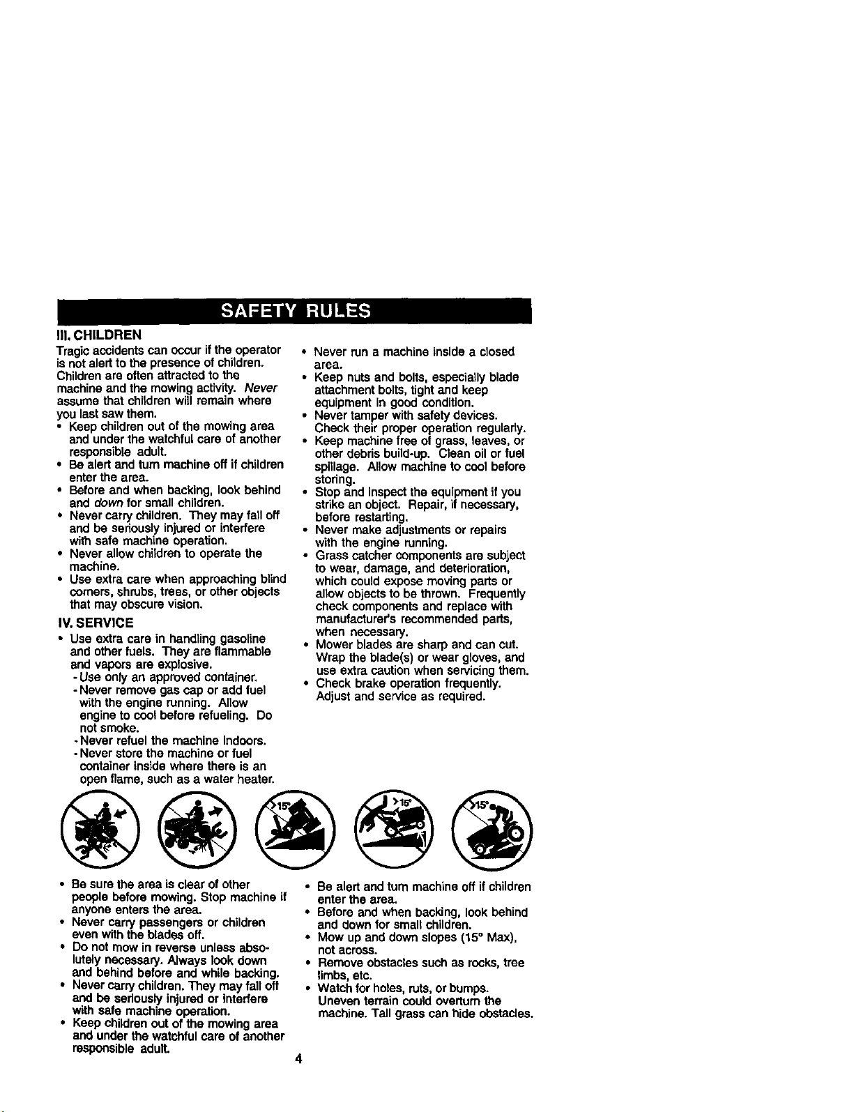
• Be sure the area is clear of other
people before mowing. Stop machine if
anyone enters the area.
• Never carry passengers or children
even with the blades off.
• Do not mow in reverse unless abso-
lutely necessary. Always look down
and behind before and while backing.
• Never carry children. They may fall off
and be seriously injured or interfere
with safe machine operation.
• Keep children out of the mowing area
and under the watchful care of another
responsible adult.
• Be alert and turn machine off ifchildren
enter the area.
• Before and when backing, look behind
and down for smalt children.
• Mow up and down slopes (15° Max),
not across.
• Remove obstacles such as rocks, tree
limbs, etc.
• Watch for holes, ruts,or bumpS.
Uneven terrain could overturn the
machine. Tall grass can hide obstacles.
Page 5
• Useslowspeed.Choosealowgearso
thatyouwillnothavetostoporshift
whileontheslope.
• Avoid starting or stoppingon a slope. If
tiros lose traction, disengage the
blades and proceed slowly straight
down the slope.
• If machine stops while going uphill,
disengage blades, shift into reverse
and back clownslowly.
• Do not turn on slopes unless neces-
sary, and then, turn slowly and gradu-
ally downhill, ifpossible.
_J-ook for thissymbol to pointout
importantsafety precautions. It means
CAUTIONll! BECOMEALERT!II YOUR
SAFETY IS INVOLVED.
_ CAUTION: Inorderto prevent
accidental starting when setting up,
transporting, adjusting or making repairs,
always disconnect spark plug wire and
place wire where It cannot contact spark
plug.
• l_CAUTION: Do not coast down a hill
in neutral, you may losecontrol of the
tractor.
CAUTION: Tow only the attachments
that are recommended by and comply
with specifications of the manufacturer of
your tractor. Use common sense when
towing. Operate only at the lowest
possiblespeed when on a slope. Too
heavy of a load, while on a slope, is
dangerous. "i3rescan lose traction with
the ground and cause you to lose control
o!your tractor.
_I_WARNING: Engine exhaust, some of
its constituents, and certain vehicle
components contain or emit chemicals
known to the State of Caiifomla to cause
cancer and birth defects or other repro-
ductive harm.
_I_WARNING: Battery posts, terminals
and related accessories contain lead and
lead compounds, chemicals known to the
State of California to cause cancer and
birthdefects or other reproductive harm.
Wash hands after handling,
Page 6
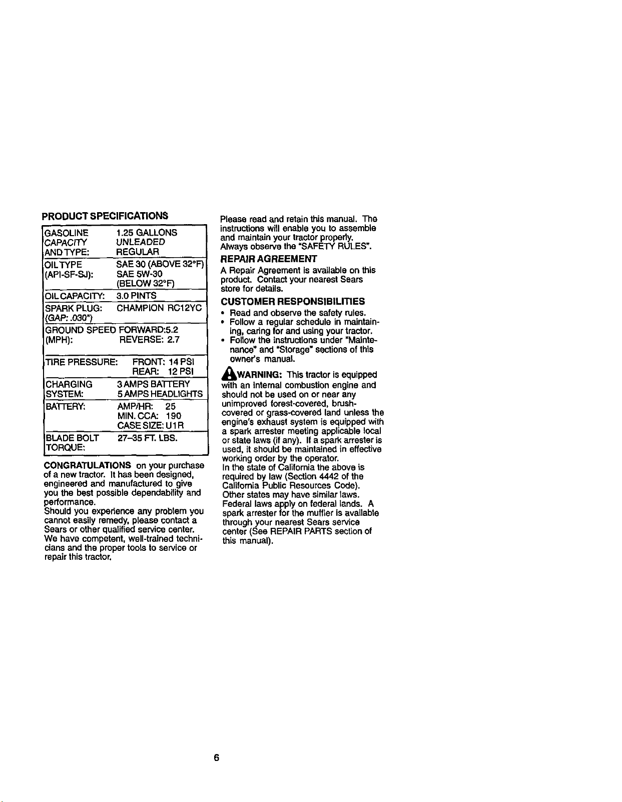
PRODUCTSPECIFICATIONS
GASOLINE 1.25GALLONS
CAPACITY UNLEADED
ANDTYPE: REGULAR
OILTYPE ShE30(ABOVE32°F
(API-SF-SJ): SAE5W-30
(BELOW32°F)
DILCAPACITY:3.0PINTS
;PARKPLUG: CHAMPIONRC12YC
SAP:.030")
SROUND SPEED FORWARD:5.2
(MPH): REVERSE: 2.7
TIRE PRESSURE: FRONT: 14 PSI
REAR: 12PSI
CHARGING 3AMPS BA'I-['ERY
SYSTEM: 5AMPS HEADLIGHTS
BA'I-I'ERY: AMP/HR: 25
MIN. CCA: 190
CASE SIZE: U1R
BLADE BOLT 27-35 FT. LBS.
TORQUE:
CONGRATULATIONS on your purchase
of a new tractor. It has been designed,
engineered and manufactured to give
you the best possible dependability and
pedormance.
Should you experience any problem you
cannot easily remedy, please contact a
Sears or other qualified service center.
We have competent, well-trained techni-
cians and the proper tools to service or
repair this tractor.
Please read and retainthis manual. The
instructionswill enable you to assemble
and maintain your tractor propedy.
Always observe the =SAFETY RULES!.
REPAIR AGREEMENT
A Repair Agreement is available on this
product. Contact your nearest Sears
store for details.
CUSTOMER RESPONSIBILITIES
• Read and observe the safety rules.
• Follow a regular schedule in maintain-
ing, caring for and using your tractor.
• Foltow the instructionsunder NMainte-
nance" and =Storage" sections of this
owner's manual
,_WARNING: This tractor is equipped
with an internal combustion engine and
should notbe used on or near any
unimproved forest-covered, brush-
covered or grass-covered land unless the
engine's exhaust system is equipped with
a spark arrester meeting applicable local
or state laws (if any). If a spark arrester is
used, it shouldbe maintained in effective
working order by the operator.
In the state of California the above is
required by law (Section 4442 of the
California Public Resources Code).
Other states may have similarlaws.
Federal laws apply on federal lands. A
spark arrester for the muffler is availabte
through your nearest Sears service
center (See REPAIR PARTS section of
this manual).
Page 7
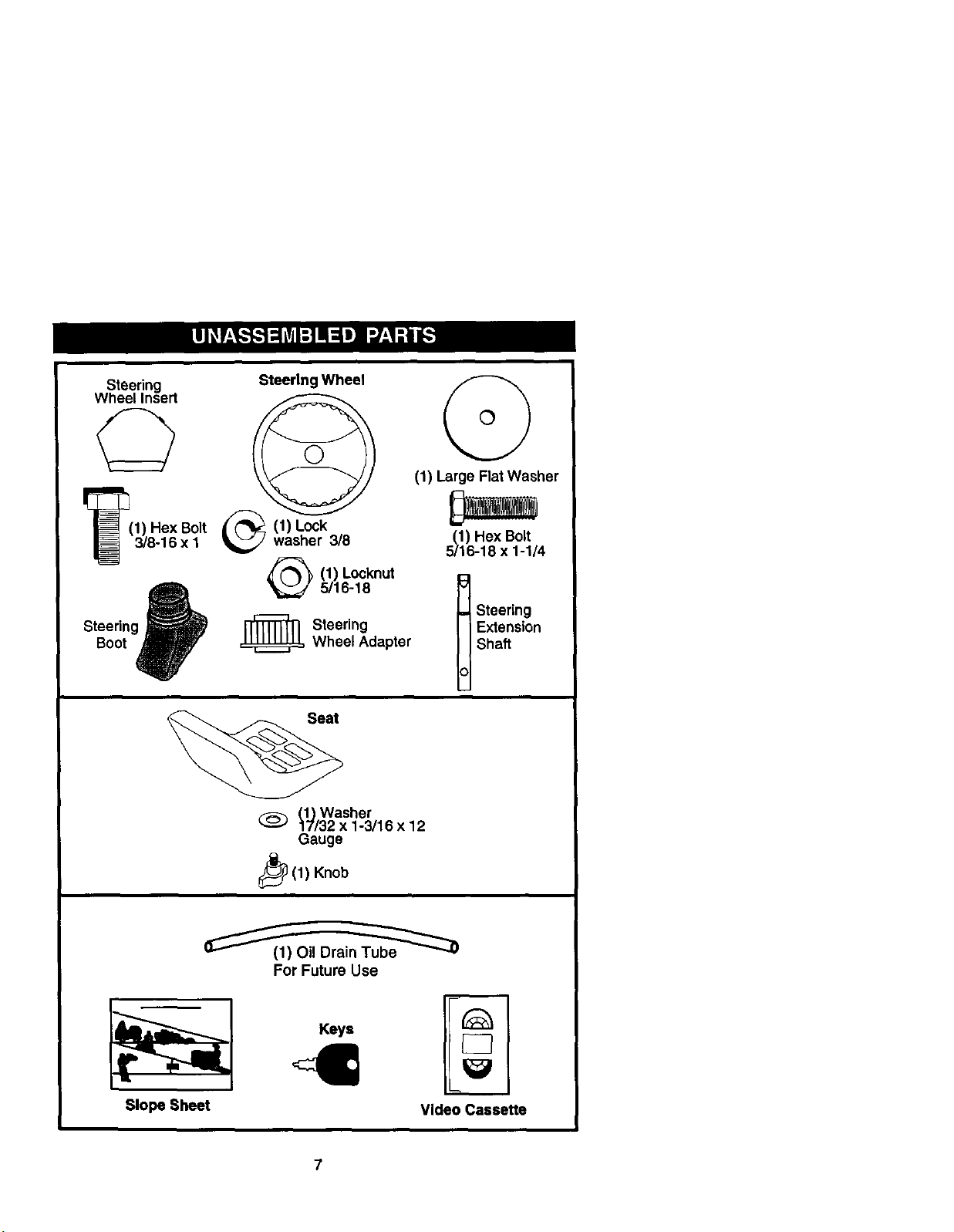
Steering
Wheel Insert
1) Hex Bolt
3/6-16 x 1
Steering Wheel
1) Lockwasher 3/8
(1) Locknut
5/16-18
(1) Large Flat Washer
/1) Hex Bolt
16-18 x 1-1/4
Steering
Boot
=_ Steering
_(1) Knob
Wheel Adapter
(1) Washer
17/32 x 1-3/16 x 12
Gauge
For Future Use
Keys
Extension
Shaft
t teering
Slope Sheet
Video Cassette
7
Page 8
Your new tractor has been assembled at the factorywith exception of those parts left
unasssmb{ed for shipping purposes. To ensure safe and proper operation of your
tractor all parts and hardware you assemble must be tightened securely. Use the
correct tools as necessary to insure proper tightness. Review the video cassette before
you begin.
TOOLS REQUIRED FOR
ASSEMBLY
A socket wrench set will make assembly
easier. Standard wrench sizes you need
are listed below.
(1) 9/16"wrench (1) Pliers
(2) 1i2"wranch (1) Utility knife
(1) Tire pressure gauge
When right or left hand is mentioned in
this manual, it means, from your point of
view, when you are in the operating
position (seated behind the steering
wheel).
TO REMOVE TRACTOR FROM
CARTON
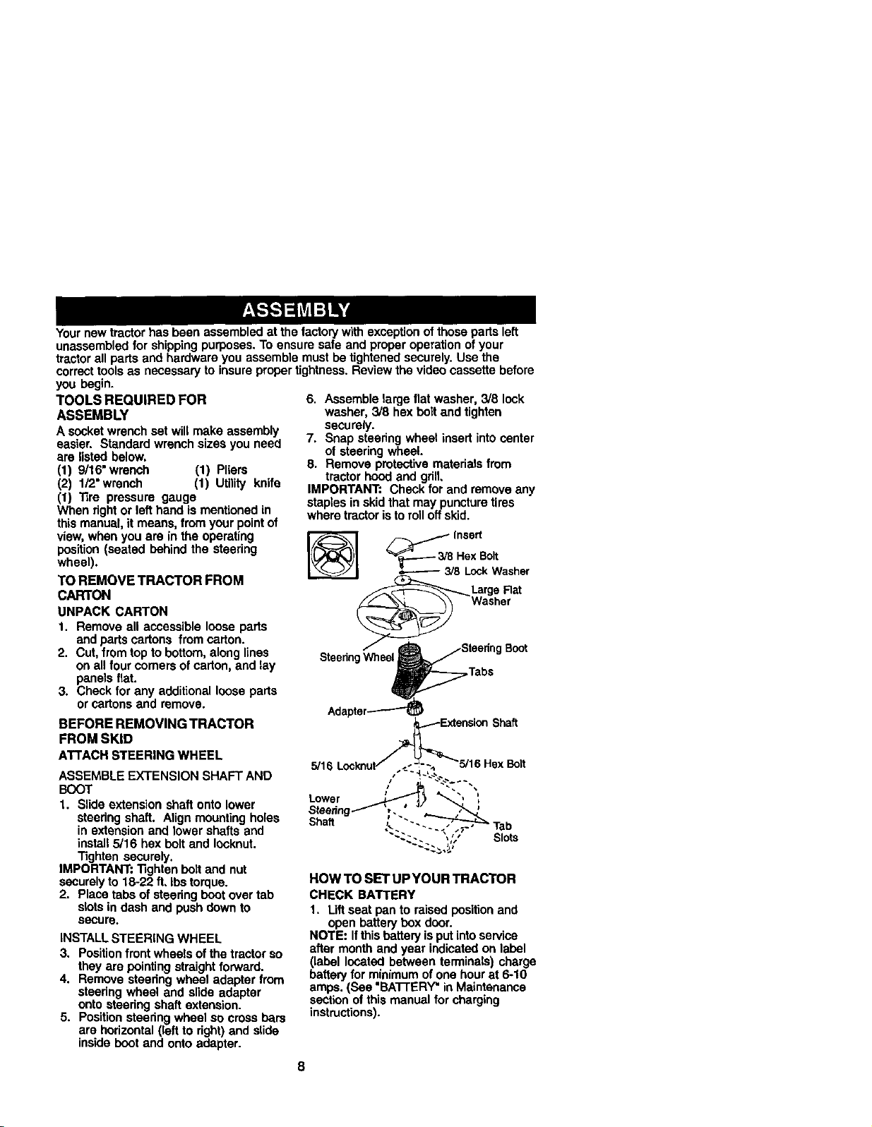
6. Assemble large flat washer, 3/8 lock
washer, 3/8 hex bolt and tighten
secureiy.
7. Snap steering wheel insert into center
of steering wheel.
8. Remove protective materials from
tractor hood and grill.
IMPORTANT: Check for and remove any
staples in skid that may puncture tires
where tractor is to rolloff skid.
-_ _ insert
3/8 Hex Bolt
3/8 LockWasher
_Large Rat
UNPACK CARTON
1. Remove all accessible loose parts
Washer
and parts cartons from carton.
2. Cut, from topto bottom, along lines
on allfour comers of carton, and lay
panels flat.
3. Check for any additional loose parts
or cartons and remove.
BEFORE REMOVING TRACTOR
Shaft
FROM SKID
ATTACHSTEERINGWHEEL
ASSEMBLE EXTENSION SHAFT AND
BOOT
1. Slide extension shaft onto lower
steedng shaft. Align mounting holes
in extension and lower shafts and
instaU5/16 hex boltand Iocknut.
Tighten securely.
IMPORTANT: "Rghtanbolt and nut
securelyto 18-22 ft, Ibs torque.
2. Place tabs of steering boot over tab
slotsin dash and push down to
secure.
INSTALL STEERING WHEEL
3. Positionfront wheels of the tractor so
they are pointing straight forward.
4. Remove steering wheel adapter from
steering wheel and slide adapter
onto steering shaft extension.
5. Position steering wheel so cross bars
are horizontal (left to right) end slide
inside boot and onto adapter.
5/16 ex Bolt
Lower
Steering
Shaft
Slots
HOW TO SET UPYOUR TRACTOR
CHECK BATTERY
1. Uft seat pan to raised positionand
open battery box door.
NOTE: Ifthis battery isput intoservice
after month and year indicated on label
(label located between terminals) charge
battery for minimum ofone hourat 6-10
amps. (See "BATTERY" inMaintenance
section of this manual for charging
instructions).
Page 9
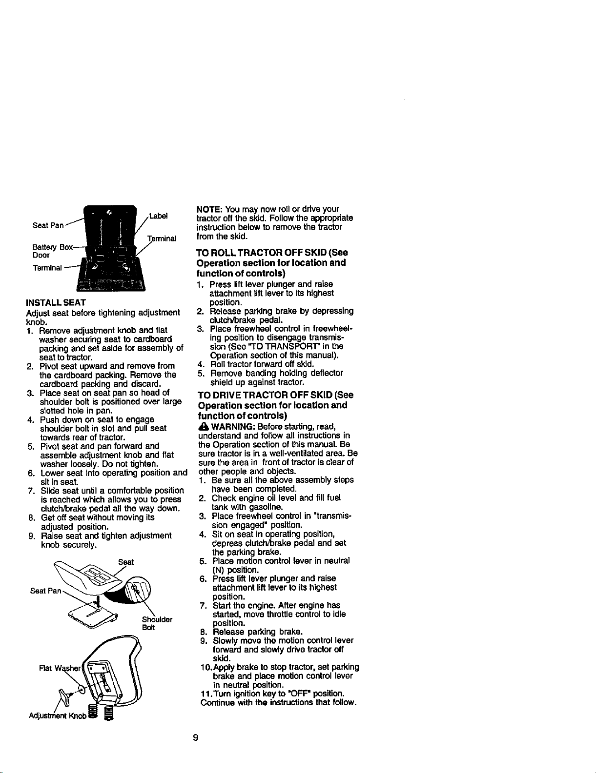
Labe_
Battery
Door
INSTALL SEAT
Adjust seat before tightening adjustment
knob.
1. Remove adjustment knob and flat
washer securing seat to cardboard
packing and set aside for assembly of
seat to tractor.
2. Pivot seat upward and remove from
the cardboard packing. Remove the
cardboard packing and discard.
3. Place seat on seat pan so head of
shoulder bolt is positioned over large
slotted hole in pan.
4. Push down on seat to engage
shoulder bolt in slot and pull seat
towards rearof tractor.
5. Pivot seat and pan forward and
assemble adjustment knob and flat
washer toosely. Do not tighten.
6. Lower seat into operating position and
sit in seat.
7. Slide seat until a comfortable position
is reached which allows you to press
clutch/brake pedal all the way down.
8. Get off seat without moving its
adjusted position.
9, Raise seat and tighten adjustment
knob securely.
Seat Pan_%ulder
NOTE: You may now rollor drive your
tractor off the skid. Follow the appropriate
instruction below to remove the tractor
from the skid.
TO ROLL TRACTOR OFF SKID (See
Operation section for location end
function of controls)
1. Press liftlever plunger and raise
attachment riftlever to its highest
position,
2. Retease parking brake by depressing
clutch/brake pedal,
3. Place freewheel control in freewheel-
ing positionto disengage transmis-
sion (See "TO TRANSPORT" in the
Operation section of this manual).
4. Rolltractor forward off skid.
5, Remove banding holding deflector
shield up against tractor.
TO DRIVE TRACTOR OFF SKID (See
Operation section for location and
function of controls)
_k WARNING: Before starting,road,
understand and follow all instructionsin
the Operation section ofthis manual. Be
sure tractor is in a well-ventilated area. Be
sure the area in front of tractoris clear of
other people and objects.
1. Be sureall the above assembly steps
have been completed.
2. Check engine oil level and fill fuel
tank with gasoline.
3. Place freewheel control in "transmis-
sion engaged" position.
4. Sit on seat in operating position,
depress clutcl'dbrakepedal and set
the parking brake.
5. Place motion control lever in neutral
(N) position.
6. Press liftlever plunger and raise
attachment lift lever to its highest
position.
7. Start the engine. After engine has
started, move throttle controlto idle
position.
8. Release parking brake.
9. Slowly move the motion control lever
forward and slowly ddve tractor off
skid.
10.Apply brake to stop tractor, set parking
brake and place motion control lever
in neutral position.
11.Turn ignition key to "OFF" position.
Continue with the instructionsthat follow.
9
Page 10
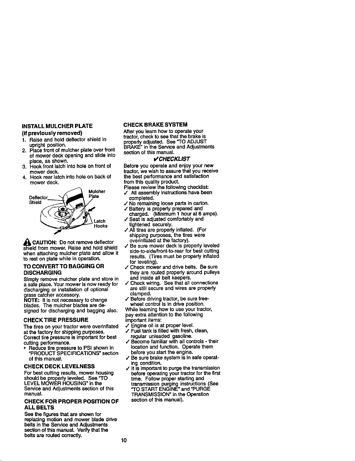
INSTALL MULCHER PLATE
(If previously removed)
1. Raise and hold deflector shield in
upright position.
2. Placefront of mulcher plate over front
of mower deck opening and slide into
place, as shown.
3. Hookfront latch into hole on front of
mower deck.
4. Hook rear latch into hole on back of
mower deck.
Plate
Shield
Latch
CAUTION: Do not remove deflector
shield from mower. Raise and hold shield
when attaching mulcher plate and allow it
to rest on plate while in operation.
TO CONVERT TO BAGGING OR
DISCHARGING
Simply remove mulcher plate and store in
esafe place. Your mower is now ready for
discharging or installation of optional
grass catcher accessory.
NOTE; It is not necessary to change
blades. The mulcherblades are de-
signed for discharging and bagging also.
CHECK TIRE PRESSURE
Thetiresonyourtractorwereovednflated
at thefactory forshippingpurposes.
Correcttirepressureisimportantfor best
cuttingperformance.
• Reducetirepressureto PSishownin
=PRODUCTSPECIFICATIONS"section
ofthismanual.
CHECK DECK LEVELNESS
For best cutting resultS, mower housing
shoutdbe propedy leveled. See "TO
LEVEL MOWER HOUSING" inthe
Service and Adjustments section of this
manual.
CHECK FOR PROPER POSITION OF
ALL BELTS
See the figuresthat are shown for
replacing motion and mower blade drive
belts in the Service and Adjustments
sectionof this manual. Verify that the
belts are muted correctly.
CHECK BRAKE SYSTEM
Afteryou leam how to operate your
tractor,check tosee that the brake is
properly adjusted. See "TO ADJUST
BRAKE" in the Service and Adjustments
section of this manual.
CHECKLIST
Before you operate and enjoy your new
tractor,we wish to assure that you receive
the best performance and satisfaction
from this qualityproduct.
Please review the following checklist:
/ All assembly instructionshave been
completed.
/ No remaining loose pads in carton.
/ Battery is propedy prepared and
charged. (Minimum 1 hour at 6 amps).
4" Seat is adjusted comfortablyand
tightened securely.
/ All tires are properly inflated. (For
shipping purposes, the tires were
overinflated at the factory).
,/Be sure mower deck is properly leveled
side-to-side/front-to-raar for best cutting
results. (13resmust be properly inflated
for leveling).
,/Check mower and drive belts. Be sum
they are routed properly around pulleys
and inside all belt keepers.
J Check widng. See that all connections
are still secure and wires are propedy
clamped.
,/Before ddving tractor, be sure free-
wheel control is in drive position.
While learning how to use your tractor,
pay extra attention to the following
importantitems:
/ Engine oil is at proper level.
,/Fuel tank is filled with fresh, clean,
regular unleaded gasoline.
/ Become familiar with all controls - their
locationand function. Operate them
before youstart the engine.
,/Be sure brake system is in safe operat-
ing condition.
,/It isimportant to purge the transmission
before operatingyour tractor for the first
time. Followproper starting and
transmission purging instructions(See
"TO START ENGINE" and "PURGE
TRANSMISSION" in the Operation
section of this manual).
10
Page 11
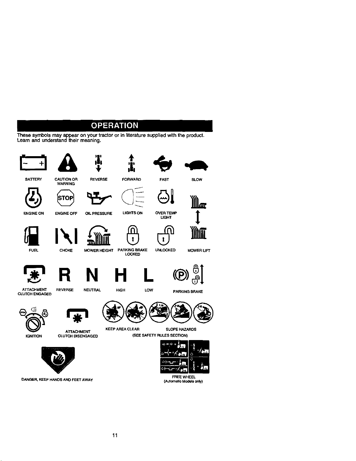
These symbols may appear on your tractor or inliterature supplied with the product.
Learn and understand their meaning.
BATi'E RY CAUTION OR REVERSE FORWARD FAST SLOW
ENGINE ON ENGINE OFF OIL PRESSURE LIGHTS ON OVER TEMP
FUEL CHOKE MOWER HEIGHT PARKING BRAKE UNLOCKED
_r_'l R N H L
ATTACHMENT REVERSE NEUTRAL HIGH LOW
CLUTCH ENGAGED
WARNING
LOCKED
LIGHT
MOWER LIFT
®5I
PARKING BRAKE
@@@@@
_(_) ATTACHMENT KEEP AREA CLEAR SLOPE HAZARDS
IGHmON CLUTCH DISENGAGED (SEE SAFETY RULES SECTION)
!
DANGER, KEEP HANDSANDFEETAWAY
FREEWHEEL
(A_omaEc Models only)
11
Page 12
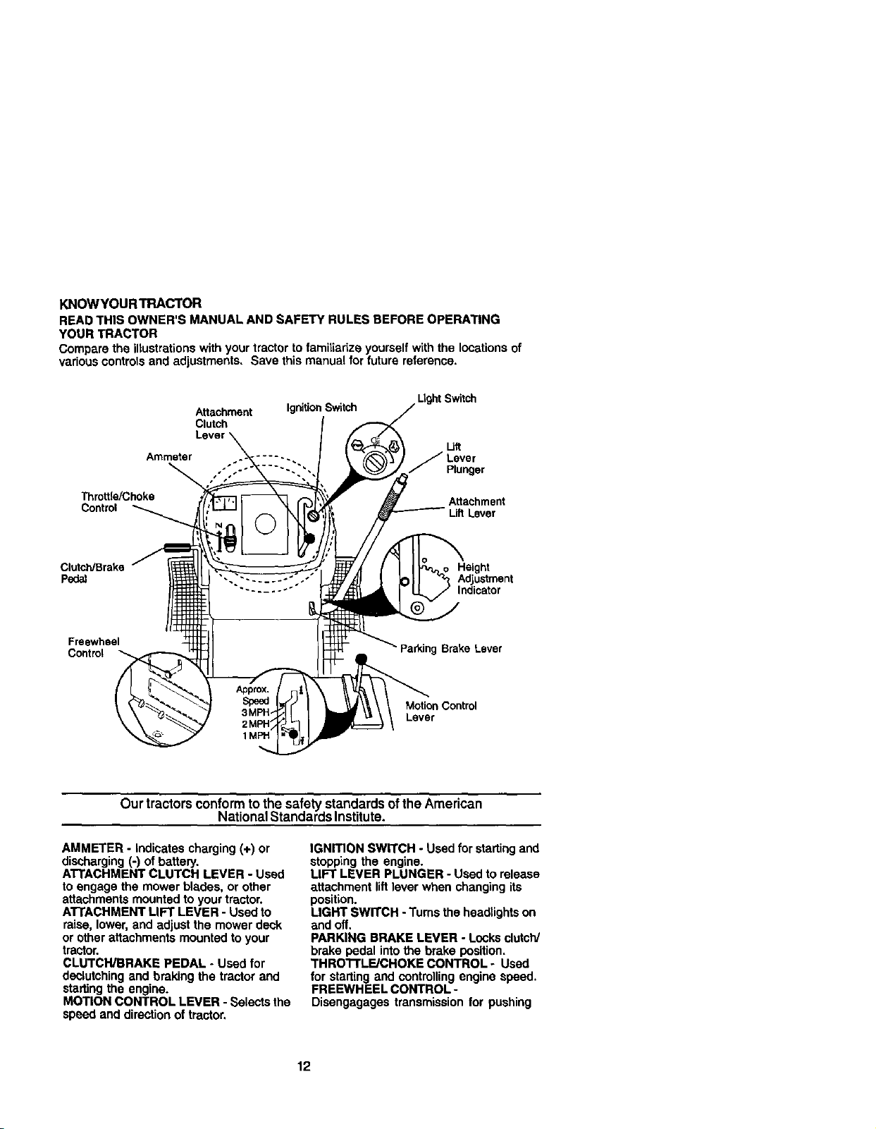
KNOWYOURTRACTOR
READ THIS OWNER'S MANUAL AND SAFETY RULES BEFORE OPERATING
YOUR TRACTOR
Compare the illustrations with your tractor to familiarize yourself withthe locations of
various controlsand adjustments. Save this manual for future reference.
Attachment Ignition Switch
Clutch
Ammeter .... -..
Ught Switch
I_iR
J Lever
Plunger
Throttle/Choke Attachment
Control Uft Lever
ClutcWBrake Height
Pedal Adjustment
Freewheel
Control Parking Brake Lever
Motion Control
Lever
Indicator
Our tractors conform tothe safety standardsoftheAmerican
National Standards Institute.
AMMETER - indicates charging (+) or
discharging (-) of battery.
ATTACHMENT CLUTCH LEVER - Used
to engage the mower blades, or other
attachments mounted to your tractor.
A'rrACHMENT LIFT LEVER - Used to
raise, lower, and adjust the mower deck
or other attachments mounted to your
tractor.
CLUTCH/BRAKE PEDAL - Used for
declutching and braking the tractor and
starting the engine.
MOTION CONTROL LEVER - Selects the
speed and direction of tractor.
IGNrrlON SWITCH - Used for startingand
stopping the engine.
LIFT LEVER PLUNGER - Used to release
attachment lift lever when changing its
position.
LIGHT SWITCH - Turns the headlights on
and off.
PARKING BRAKE LEVER - Locks clutch/
brake pedal into the brake position,
THRO'I'FLE/CHOKE CONTROL - Used
for starting and controllingengine speed.
FREEWHEEL CONTROL-
Dissngagages transmission for pushing
12
Page 13
The operation of any tractorcan result in foreign objectsthrown into
the eyes, which can result in severe eye damage. Alwayswear safety
glasses or eye shields while operating your tractor or performingany
adjustments or repairs. We recommend a wide vision safety mask
over spectacles or standard safety glasses.
HOWTO USEYOURTRACTOR
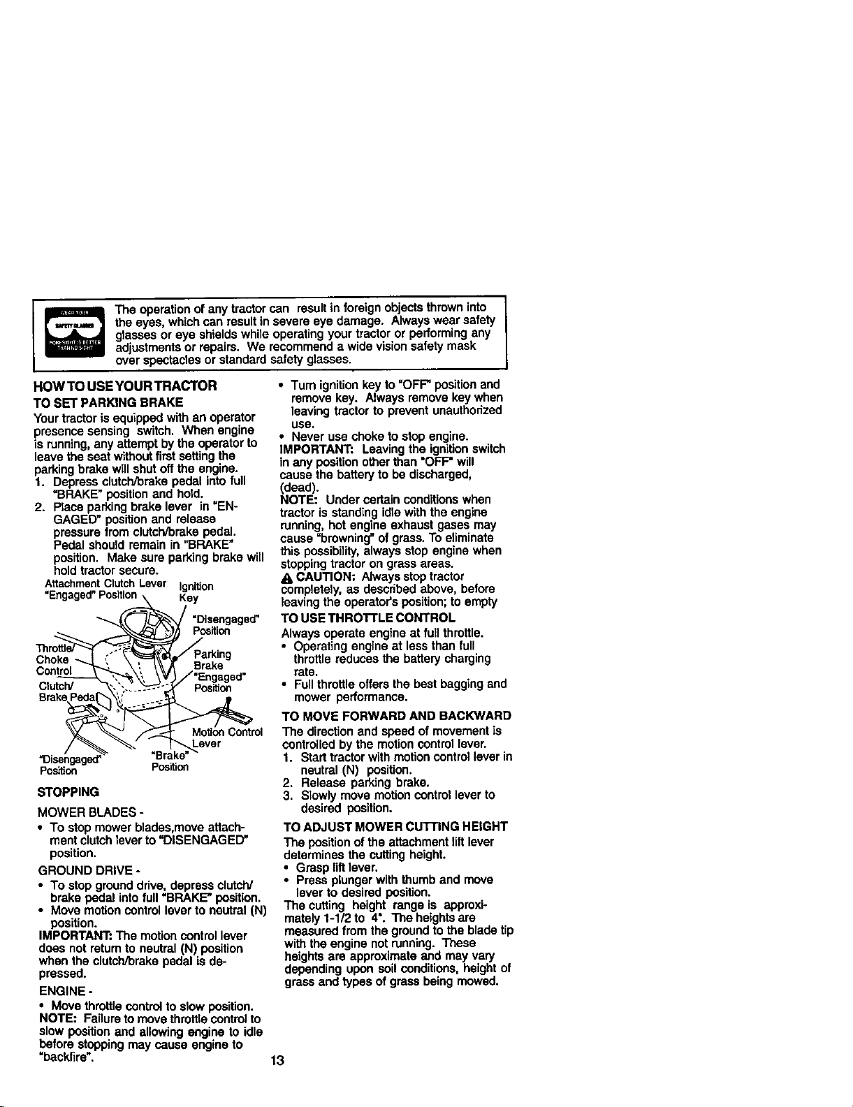
TO SET PARKING BRAKE
Your tractor is equipped with an operator
presence sensing switch. When engine
is running, any attempt by the operator to
leave the seat without first settingthe
parking brake will shut offthe engine.
1. Depress clutch/brake pedal into full
=BRAKE" position and hold.
2. Place parking brake lever in =EN-
GAGED" position and release
pressure from clutch/brake pedal.
Pedal should remain in "BRAKE"
position. Make sure parking brake will
hold tractor secure.
AttachmentClutchLever IgniUon
"Engaged"Position Kay
Position
Choke
Control Brake
Clu_lY pos_on
BmkE
Motion Control
"Disengaged' "Brake"_ever
Pos_on Position
STOPPING
MOWER BLADES -
• To stop mower blades,move attach-
ment clutch lever to "DISENGAGED"
position.
GROUND DRIVE -
• To stop ground drive, depress clutch/
brake pedal into full "BRAKE" position.
• Move motion control lever to neutral (N)
position.
IMPORTANT: The motion controllever
does not return to neutral (N) position
when the clutch/brake pedal is de-
pressed.
ENGINE -
• Move throttle controlto slow position.
NOTE: Failure to move throttlecontrol to
slow position end allowing engine to idle
before stopping may cause engine to
=backfire".
• Turn ignition key to =OFF" positionand
remove key. Always remove key when
leaving tractor to prevent unauthorized
USe.
• Never use choke to stop engine.
IMPORTANT: Leaving the ignition switch
in any position other than =OFF"will
cause the battery to be discharged,
(dead).
NOTE: Under certain conditions when
tractor is standing idle with the engine
running, hot engine exhaust gases may
cause =browning" of grass. To eliminate
this possibility,always stop engine when
stopping tractor on grass areas.
A CAUTION: Always stop tractor
completely, as described above, before
leaving the operator's position; to empty
TO USE THRO'I'FLE CONTROL
Always operate engine at full throttle.
• Operating engine at less than full
throttle reduces the battery charging
rate.
• Full throttle offers the best bagging and
mower performance.
TO MOVE FORWARD AND BACKWARD
The direction and speed of movement is
controlled by the motion control lever.
1. Start tractorwith motion control lever in
neutral (N) position.
2. Release parking brake.
3. Slowly move motion control lever to
desired position.
TO ADJUST MOWER CUTI'ING HEIGHT
The position of the attachment lift lever
determines the cutting height.
• Grasp liftlever.
• Press plunger with thumb and move
lever to desired position.
The cuffing height range is approxi-
mately 1-1/2 to 4". The heights are
measured from the ground to the blade tip
with the engine not running. These
heights are approximate end may vary
depending upon soil conditions, height of
grass and types of grass being mowed.
13
Page 14
• The average lawn should be cut to
approximately 2-1/2 inches dudno the
cool season and to over 3 inches
dudng hot months. For healthier and
better lookinglawns, mow often and
after moderate growth.
• For best cuttingperformance, grass
over 6 inches in height should be
mowed_. Make the first cut
relatively high;the second to desired
height.
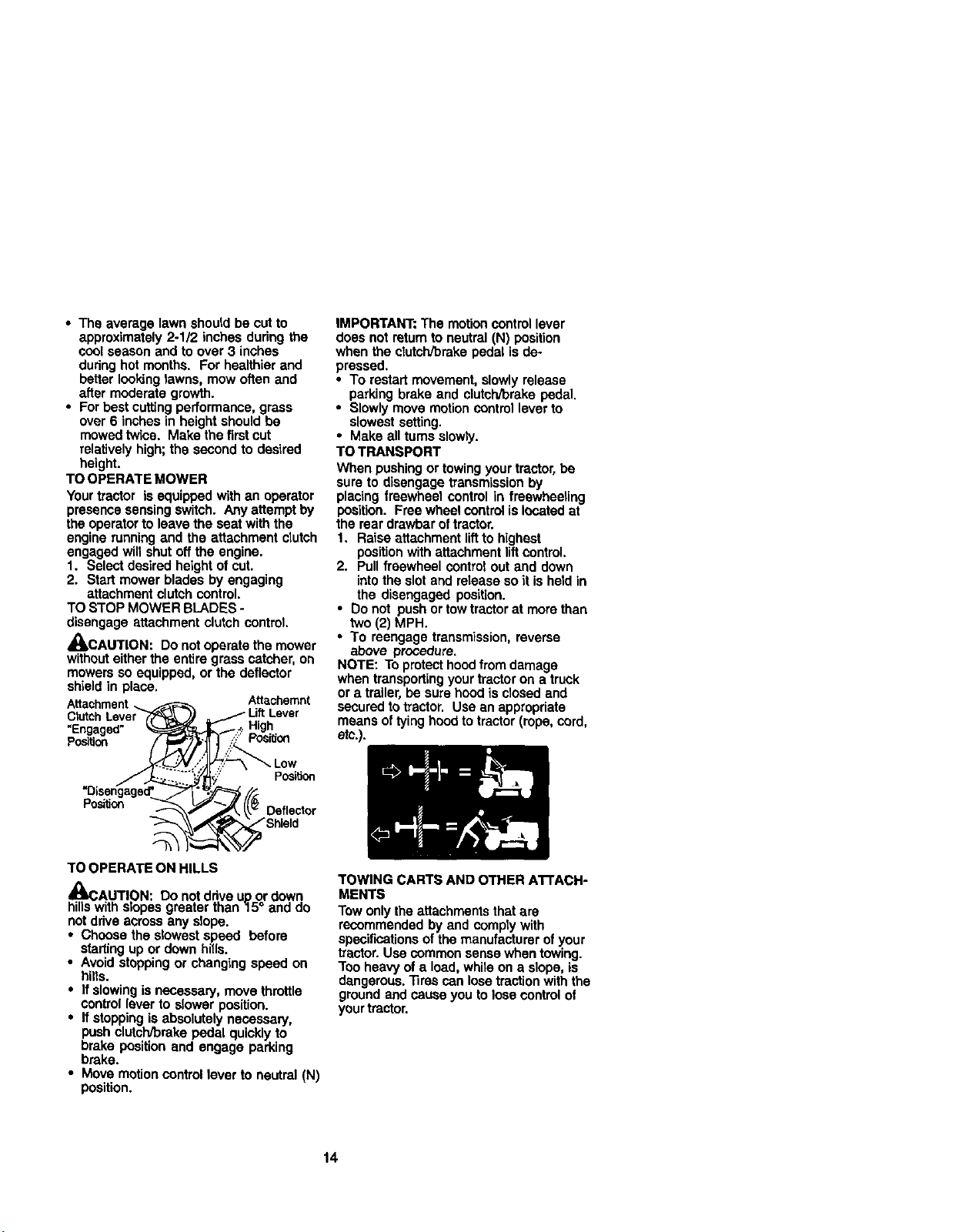
TO OPERATE MOWER
Your tractor is equipped with an operator
presence sensing switch. Any attempt by
the operator to leave the seat with the
engine running and the attachment crutch
engaged will shut off the engine.
1, Select desired height of cut.
2. Start mower blades by engaging
attachment clutch control.
TO STOP MOWER BLADES -
disengage attachment clutch control.
_kCAUTION: Do not operate the mower
withouteither the entire grass catcher, on
mowers so equipped, or the defied,or
shield in place.
"Engaged" .,High
Posi_on
Attachemnt
IMPORTANT: The motion control lever
does not returnto neutral (N) position
when the clutch/brake pedal is de-
pressed,
• To restart movement, slowly release
parking brake and clutch/brake pedal.
• Slowly move motion contrel lever to
slowest setting.
• Make all toms slowly.
TO TRANSPORT
When pushing ortowing your tractor, be
sure to disengage transmission by
placing freewheel control in freewheeling
position. Free wheel control is located at
the rear drawbar of treotor.
1. Raise attachment lift to highest
position with attachment lift control.
2. Pull freewheel control out and down
into theslot and release so it is he_din
the disengaged position.
• Do not push or tow tractorat more than
two (2) MPH.
* To reengage transmission, reverse
above procedure.
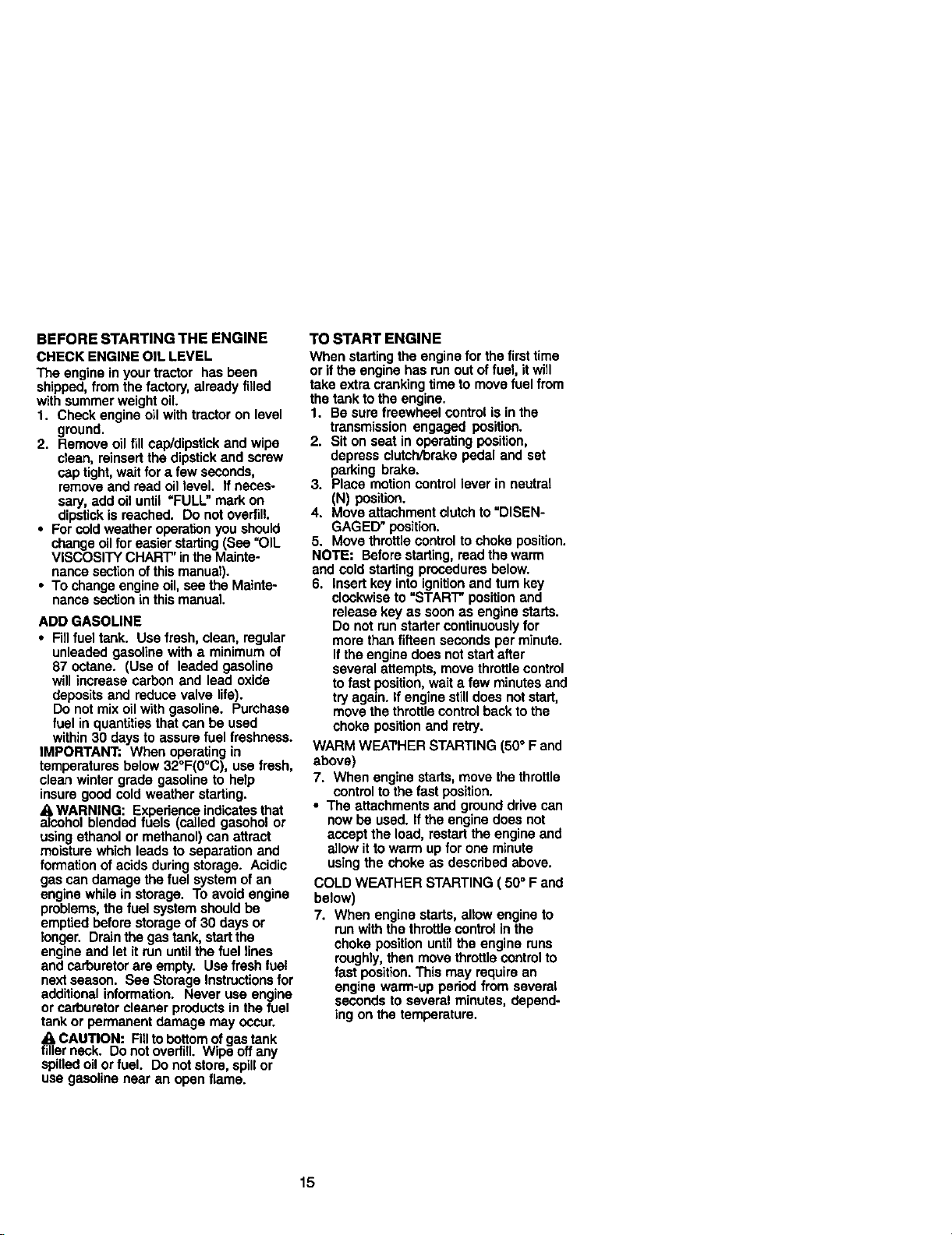
NOTE: To protect hoodfrom damage
when transportingyour tractor on atruck
or a trailer, be sure hood is closed and
secured totractor. Use an appropriate
means of tying hood to tractor(rope, cord,
etc.).
TO OPERATE ON HILLS
_3AUTION: Do not ddve upor dowse
hillswith slopes greater than "15 and
not drive across any slope.
• Choose the stowest speed before
starting up or down hills.
• Avoid stopping or changing speed on
hills.
• If slowingis necessary, move throttle
controllever to slower position.
• If stopping is absolutely necessary.
push clutch/brake pedal quickly to
brake position and engage parking
brake.
• Move motioncontrol lever to neutra| (N)
position.
TOWING CARTS AND OTHER AI"rACH-
MENTS
Tow only the attachments that are
recommended by and comply with
spe_t'w..ationsof the manufacturer of your
tractor.Use common sense when towing.
Too heavy of a load, while on a slope, is
dangerous. "Rrescan lose tractionwith the
ground and cause you to lose control of
yourtractor,
14
Page 15
BEFORE STARTING THE ENGINE
CHECK ENGINE OIL LEVEL
The engine inyour tractor has been
shipped, from the factory, already filled
with summer weight oil.
1. Check engine oil withtractor on level
ground.
2. Remove eil fill cap/dipstick and wipe
clean, reinsert the dipstickand screw
cap tight,wait for a few seconds,
remove and read oil level. If neces-
sary, add oil until =FULL" mark on
dipstick is reached. Do not overfill.
• For coldweather operationyou should
change oil for easier starting(See "OIL
VISCOSITY CHART" inthe Mainte-
nance sectionof this manual).
• To change engine oil,see the Mainte-
nance section in thismanual.
ADD GASOLINE
• FUlfuel tank. Use fresh, clean, regular
unleaded gasoline with a minimum of
87 octane. (Use of leaded gasoline
will increase carbon and lead oxide
deposits and reduce valve life).
Do not mix oil with gasoline. Purchase
fuel in quantities that can be used
within 30 days to assure fuel freshness.
IMPORTANT: When operating in
temperatures below 32°F(0°C), use fresh,
clean winter grade gasoline to help
insure good cold weather starting.
a, WARNING: Experience indicates that
alcohol blended fuels (called gasohol or
using ethanol or methanol) can attract
moisture which leads to separation and
formation of acids duringstorage. Acidic
gas can damage the fuel system of an
engine while in storage. To avoid engine
problems, the fuel system shouldbe
emptied before storage of 30 days or
longer. Drainthe gas tank, start the
engine and let it run untilthe fuel lines
and carburetor are empty. Use fresh fuel
next season. See Storage Instructionsfor
additional information. Never usa engine
or carburetor cleaner products in the fuel
tank or permanent damage may occur.
_11CAUTION: Fill tobottom of gas tank
filler neck. Do not overfill. Wipe off any
spilled oil or fuel. Do not store, spillor
use gasoline near an open flame.
TO START ENGINE
When starting the engine for the first time
or if theengine has run out offuel, it will
take extra cranking time to move fuel from
the tank to the engine.
1. Be sure freewheel control is in the
transmission engaged position.
2. Sit on seat in operating position,
depress clutch/brake pedal and set
parking brake.
3. Place motion controllever in neutral
(N) position.
4. Move attachment clutch to "DISEN-
GAGED" position.
5. Move throttle controlto choke position.
NOTE: Before starting, read the warm
and cold starting procedures below.
6. Insert key into ignitionand turn key
clockwise to "STAR'I" position and
release key as soon as engine starts.
Do not run starter continuouslyfor
more than fifteen seconds per minute.
If the engine does not start after
several attempts, move throttle control
to fast position, wait a few minutes and
try again. If engine still does not start,
move the throttle controlback to the
choke positionand retry.
WARM WEA'rI-IER STARTING (50° F and
above)
7. When engine starts, move the throttle
control to the fast position.
• The attachments and ground drive can
now be used. If the engine does not
accept the load, restart the engine and
allow it to warm up for one minute
using the choke as dascribed above.
COLD WEATHER STARTING ( 50° F and
below)
7. When engine starts, allow engine to
run with the throttlecontrol in the
choke position untilthe engine runs
roughly, then move throttle control to
fast position. This may require an
engine warm-up period from several
seconds to several minutes, depend-
ing on the temperature.
15
Page 16

AUTOMATIC TRANSMISSION WARM UP
Before drivingthe unit incold weather,
the transmission shouldbe warmed up as
follows:
1. Be surethe tractor is on level ground.
2. Place the motion controllever in
neutral. Release the parking brake
and let the clutch/brake slowly return
to operating position.
3. Allow one minute for transmissionto
warm up. This can be done during
the engine warm up period.
• The attachments can also be used
during the engine warm-up period alter
the transmissionhas been warmed up.
NOTE: Ifat a high altitude (above 3000
feet) or in coldtemperatures (below 32 F)
the carburetor fuel mixture may need to
be adjusted for best engine performance.
See "TO ADJUST CARBURETOR" in the
Service and Adjustments sectionof this
manual.
PURGE TRANSMISSION
r_eCAUTION: Never engage or disengage
ewheel lever while the engine is
running.
To ensure properoperation and perfor-
mance, it is recommended that the
transmissionbe purged before operating
tractorfor the firsttime. This procedurewill
remove any trapped air inside the trans-
mission which may have developed during
shippingof your tractor.
IMPORTANT: Should your transmission
requireremoval for service or replacement,
it should be purged alter reinstallation
before operatingthe tractor.
1. Place tractor safely on level surface
with engine off and parking brake set,
2. Disengage transmission by placing
freewheel control in freewheeting
position(See "TO TRANSPORT" in
this section of manual).
3. Sittingin the tractor seat, start engine.
Afterthe engine is running, move
throttlecontrol to slow position.With
motioncontrol lever in neutral (N)
position, slowly disengage clutch/
brake pedal.
4. Move motioncontrol lever to full
forward position and hold for five (5)
seconds. Move lever to full reverse
positionand hold for five (5) seconds.
Repeat this procedure three (3) times.
NOTE: Duringthis procedure there will
be nomovement of drivewheels. The air
is being removed from hydraulicdrive
system.
5. Move motion control lever to neutral
(N) position. Shut- off engine and set
parking brake.
6. Engage transmission by placing
freewheel control in driving position
(See "TO TRANSPORT" in this
section of manual).
7. Sittingin the tractor seat, start
engine. After the engine is running,
move throttle control to half (1/2)
speed. With motion control lever in
neutral (N) position, slowly disen-
gage clutch/brake pedal.
8, Slowly move motion control lever
forward, after the tractor moves
approximately five (5) feet, slowly
move motion control lever to reverse
position.After the tractor moves
approximately five (5) feet returnthe
motion controllever to the neutral (N)
position. Repeat this procedure with
the motion control lever three (3)
times.
Your tractor is now purged and now
ready for normal operation.
16
Page 17
MOWING TIPS
• Mower should be properly leveled for
best mowingperformance. See "TO
LEVEL MOWER HOUSING" in the
Service and Adjustments section of
this manual.
• The left hand side of mower should be
used for trimming.
• Drive so that clippings are discharged
onto the area that has been cut. Have
the cut area to the rightof the tractor.
This will resuttin a more even distribu-
tion of clippings and more uniform
cutting.
• When mowing large areas, start by
turning to the rightso that clippings will
discharge away from shrubs, fences,
driveways, etc. After one or two
rounds, mow in the opposite direction
making left hand turns until finished.
• Ifgrass is extremely tall, it should be
mowed twice to reduce load and
possible fire hazard from dried
clippings. Make first cut relatively
high;the second to the desired height.
• Do not mow gross when itiswet. Wet
grass will plug mower and leave
undesirable clumps. Allow grass to
dry before mowing.
• Always operate engine st full throttle
when mowing to assure better mowing
performance and proper discharge of
material Regulate ground speed by
selecting a low enough gear to give
the mower cutting performance as well
as the quality of cut desired.
• When operating attachments, select a
ground speed that will suitthe terrain
and give best performance of the
attachment being used.
MULCHING MOWING TIPS
IMPORTANT: For best performance,
keep mower housing free of built-up
grass and trash. Clean after each use.
• The special mulchingblade will rscut
the grass clippings many times and
reduce them in size sothat as they fall
onto the lawn they will disperse intothe
grass and not be noticed. Atso. the
mulched grass will biodegrade quickly
to provide nutrients for the lawn.
Always mulch with your highest engine
(bleds) speed as this will provide the
best recuttingaction of the blades.
• Avoid cutting your lawn when it is wet.
Wet grass tends to form clumps and
interferes with the mulching action.
The best time to mow your lawn is the
early afternoon. At this time the grass
has dried and the newly cut area will
notbe exposed to the directsun.
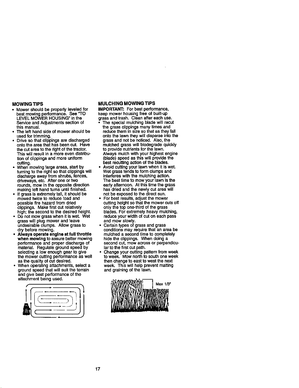
• For best results,adjust the mower
cuttingheight sothat the mower cuts oft
onlythe top one-third of the grass
blades. For extremely heavy mulching,
reduce your width of cut on each pass
and mow slowly.
• Certain types of grass and grass
conditions may require that an area be
mulched a second fims to completely
hide the clippings. When doing a
second cut, mow across or perpendicu-
larto the first cut path.
• Change yourcutting pattern from week
toweek. Mow northtosouth one week
then change to east towest the next
week. This will help prevent matting
and graining of the lawn.
17
Page 18
GENERAL RECOMMENDATIONS
The warranty onthis tractordoes not
cover items that have been subjectedto
operatorabuse or negligence. To r_ive
faltvalue from the warranty, operator must
maln_in tractor as instructedin this
manual.
Some adjustments will need to be made
periodicallyto property maintain your
tractor.
All adjustments in the Se_ce and
Adjustmentssection of this manual should
be checked at leastonce each season.
• Once a year you should replace the
spark plug, clean or replace air filter,
and check blades and beltsfor wear. A
new spark plug and clean air filter
assure proper air-fuel mixture and help
your engine run better and last longer.
BEFORE EACH USE
1. Check engine oil level.
2. Check brake operation.
3. Check tire pressure.
4. Check operator presence and
intedeck systems for proper opera-
tion.
5. Check for loose fasteners.
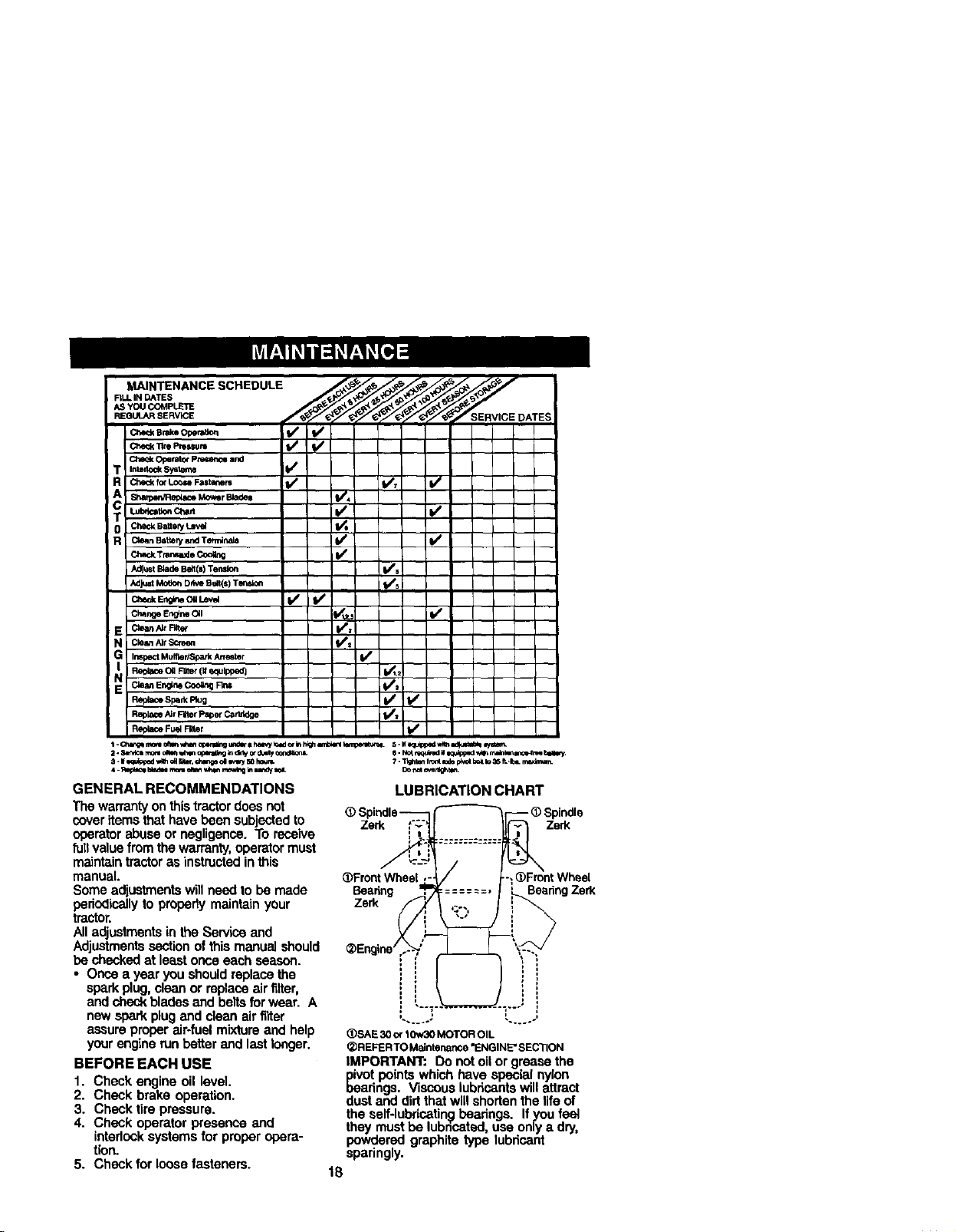
LUBRICATION CHART
_) Spindle_
.............
_Front Wheel
Beadng ====--=,
Zerk _ ,;..,
_Engine ..--
IMPORTANT: Do notoil or grease the
pivot points which have special nylon
bearings. Viscous lubricantswill attract
dust and dirt that willshodan the lifeof
the self-lubdc_tin_ beadngs. If you feal
they must be lubncated, use only a dry,
sparingly.
Y
1
_)SAE30o¢10w30MOTOROIL
• )REFERTO Maintenance "ENGINE'SECTION
powdered graphite type lubricant
-- _)Spindle
_ Zerk
FrontWheel
18
ngZerk
Page 19

TRACTOR
Always observe safety rules when
performing any maintenance.
BRAKE OPERATION
Iftractor requires more than six (6) feet
stopping distance at high speed in
highestgear, then brake must be
ad usted. (See "TO ADJUST BRAKE" in
the Service and Ad ustmants section of
this manuat).
TIRES
• Maintain proper air pressure in all tires
(See "PRODUCT SPECIFICATIONS"
section of this manuaJ).
• Keep tires free of gasoline, oil, or
insect controlchemicals which can
harm rubber.
• Avoidstumps, stones,deep ruts,sharp
objects and other hazards that may
cause tire damage.
NOTE: To seal tire punctures and
prevent flat tires due to slow leaks, tire
sealant may be purchased from your
local parts dealer. 33rosealant also
prevents tire dry rot and corrosion.
OPERATOR PRESENCE SYSTEM
Be sure operator presence and interlock
systems are working properly. If your
tractor does not function as described,
repair the problem immediately.
• The engine should not start unless the
brake pedal is fullydepressed and
attachement clutchcontrol is in the
disengaged position.
• When the engine is running, any
attempt by the operator to leave the
seat without first settingthe parking
brake should shut offthe engine.
• When the engine is running and the
attachment clutch is engaged, any
attempt by the operator to leave the
seat should shutoff the engine.
• The attachment clutch should never
operate unless the operator is in the
seat.
BLADE CARE
For best results mower blades must be
keptsharp. Replace bent or damaged
blades.
BLADE REMOVAL
1. Raise mower to highest position to
allow access to blades.
2. Remove hex bolt, lockwasher and
flat washer sscuring blade.
3. Installnew or resharpened blade with
trailingedge up towards deck as
shown.
IMPORTANT: To ensure properassembly,
center hole in blade must align with star
on mandrel assembly.
4. Reassemble hex bolt, lock washer
and flat washer in exact order as
shown.
5. Tighten bolt securely (27-35 Ft. Lbs.
torque).
IMPORTANT: Blade bolt isgrade 8 heat
treated.
TrailingEdgeUp MandrelAssembly
Blade Center
Hole
Rat Washer,
LockWashe
Ge---Hsx Boltq
*AGrade8 heattreatedboltcanbe identified
bysixlinesonthebolt head.
TO SHARPEN BLADE
NOTE: We do not recommend sharpen-
ing blade - but ifyou do, be sure the
blade is balanced.
Care shouldbe taken to keep the blade
balanced. An unbalanced blade will
cause excessive vibration and eventual
damage to mower and engine.
• The blade can be sharpened with a file
or on a grindingwheel. Do not attempt
to sharpen while on the mower.
• To check blade balance, you willneed
a 5/8" diameter steel bolt, pin, or a cone
balancer. (When using a cone bal-
ancer, follow the instructionssupplied
with balancer.)
NOTE: Do not use a nail for balancing
blade. The lobes of the center hole may
appear to be centered, but are not.
• Slide blade on to an unthreaded
portionof the steel bolt or pin and hold
the bolt or pin parallel with the ground.
If blade is balanced, it should remain in
a horizontal position. If either end of
the blade moves downward, sharpen
the heavy end untilthe blade is
balanced.
Blade
BATTERY
Your tractor has a battery charging system
which is sufficientfor normal use. How-
ever, periodic charging of the battery with
an automotive charger will extend its life.
19
Page 20

• Keep battery and terminals clean.
• Keep battery bolts tight.
• Keep small vent holes open.
• Recharge at 6-10 amperes for 1 hour.
NOTE: The originalequipment battery on
yourtractor ismaintenance free, Do not
attemptto open or remove capsor covers.
Addingor checking level of electrolyte is
notnecessary.
TO CLEAN BATI"ERY AND TERMINALS
Corrosion and dirt on the battery and
terminalscan cause the battery to "teak"
power.
1. Open battery box deer.
2. DisconnectBLACK battery cable first
then RED batterycable and remove
batteryfrom tractor.
3. Rinse the battery with plain water and
dry.
4, Clean terminals and battery cable ends
with wire brush until bright.
5. Coat terminals with grease or petro-
leum jaily,
6. Reinstallbattery (See "REPLACING
BATfERY" in the SERVICE AND
ADJUSTMENTS section ofthis
manual).
V-BELTS
Check V-beltsfor deterioration and wear
after 100 hoursof operationand replace if
necessary.The belts are not adjustable.
Replace baits ifthey begin to slipfrom
wear.
TRANSAXLE COOLING
The transmissionfan and cooling fins
shouldbe kept clean to assure proper
cooling.
Do notattempt to clean fan or transmission
while engine is running or while the
transmissionis hoLTo prevent possible
damage to seals, do not use high pressure
water or steam toclean transaxle.
• Inspect coolingfan to be sure fan blades
are intact and clean.
• Inspect coolingfins for dirt,grass
clippingsand other matadals. To
preventdamage to seals, do not use
compressed air or high pressuresprayer
toclean cooling_ns.
TRANSAXLE PUMP FLUID
The transex_ewas sealed at the factory
and fluid maintenance is not required for
the lifeofthe transexle. Should the
transexle ever leak or require servicing,
contactyour nearest authorizedservice
center/department.
ENGINE
LUBRICATION
Only use high quality detergent oil rated
withAPI serviceclassification SF-SJ.
Select the oil's SAE viscositygrade
according to your expected operating
temperature.
P_IEwn<_lrt_ _l
NOTE: Althoughmulti-viscoaityoils (5W301
10W30 etc.) improve startingin cold
weather, these mulfi-viscosity oilswilt
resultin increased oil consumptionwhen
used above 32°E Check yourengine oil
level mere frequently to avoid possible
engine damage from runninglow on oil.
Change the oil after every 25 hours of
operationor at least once a year if the
tractoris not usedfor 25 hoursin one year.
Check the crankcase oil level before
startingthe engine and aftereach eight (8)
hours of operation."lightenoilfill cap/
dipsticksecurelyeach time you checkthe
oil levai,
TO CHANGE ENGINE OIL
Determine temperature range expected
beforeoil change. All oilmustmeet API
service clessification SF-SJ.
• Be sure tractor ison level surface.
• Oil will drain mere freely when warm.
• Catch oil in a suitable container.
1. Removeoil fill cap/dipstick. Be careful
nottoallow dirtto enterthe engine
when changing oil.
2. Remove cap from end ofdrainvalve
and install the drain tuba onto the
fitting.
3. Unlock drain valve by pushinginward
snghtiyand turning counterclockwise.
4. To open. pullout on the drainvalve.
5. Afteroil has drained completely, close
and lock the drain valve bypushing
inward and turningclockwice untilthe
pin is in the locked position as shown.
6. Remove the drain tuba and replacethe
cap onto to the end ofthe drain valve.
7. Refill engine with oil through oil titl
dipstick tuba. Pour slewiy. Do net
overfill. For approximatecapacity see
"PRODUCT SPECIFICATIONS" section
of this manual.
8. Use gauge on oil fill cap/dipstickfor
checking level. Be sure dipstickcap is
tightened securely for accurate
reading. Keep oil at =FULL" line on
dipstick.
2O
Page 21

Oil DrainValve
Closed _ DrainTube
Cap_
CLEAN AIR SCREEN
Air screen must be kept free of dirt and
chaff to prevent engine damage from
overheating. Clean with a wire brush or
compressed air to remove dirt and
stubborndried gum f]bem.
ENGINE COOLING FINS
Remove any dust, dirt oroil from engine
coolingfins to prevent engine damage
from overheating.
1. Remove screws from blower housing
and lifthousing and dipstick tube
assembly off engine.
2. Cover oil fill opening to prevent entry
ofdirt.
3. Use compressed air or stiff bristle
brush to thoroughly clean engine
cooling fins.
4. To reassemble, reverse above
procedure. BlowerHousing
Screws_Screws
EngineJi_2_ - ark
Fins _-,-w
AIR FILTER
Your engine will not run propedy using a
dirty air filter. Clean the foam pre-cleaner
after every 25 hoursof operation orevery
season, Service paper cartridge every
100 hours of operation or every season,
whichever occurs first.
Service air cleaner more often under
dusty conditions.
I. Remove knob(s) and cover.
TO SERVICE PRE-CLEANER
2. Slide foam pre-cleaner off cartridge.
3. Wash it inliquid detergent and water.
4. Squeeze it dry ina clean cloth.
5. Saturate it in engine oil. Wrap it in
clean, absorbent cloth and squeeze to
remove excess oil.
NOTE: If very dirtyor damaged, replace
pre-cleaner.
6. Reinstall pre-cleaner over cartridge.
7. Reinstall cover and secure with
knob(s).
TO SERVICE CARTRIDGE
1. Remove cartridge nut.
2. Carefully remove cartridge to prevent
debris from entering carburetor. Clean
base carefully to prevent debris from
entering carburetor.
3. Clean cartridge by tapping gently on
flat surface.
NOTE: If very dirty or damaged, replace
cartridge.
4. Reinstall cartridge, nut, prscleaner,
cover and secure with knob(s).
IMPORTANT: PstroTeumsolvents,such as
kerosene,are notto be usedto deanthe
cartridge.Tipsymay causedeteriorationofthe
osrtddge. Donotoilcartridge.Do notuse
pressurizedair to cleanor dryosrtridgs.
Cover
_ Knob
Cover _// Cartridge
-___ Nut
Foam Pre-_Y_"_ Cartridge
Paper
Cleaner _Bass
MUFFLER
Inspect and replace corroded muffler and
spark arrester (if equipped) as it could
create a fire hazard and/or damage.
SPARK PLUGS
Replace spark plugs at the beginning of
each mowing season or after every 100
hours of operation, whichever occursfirst.
Spark plug type and gap setting are
shown in "PRODUCT SPECIFICATIONS"
section of this manual.
IN-LINE FUEL FILTER
The fuel filter should be replaced once
each season. If fuel filter becomes
clogged, obstructingfuel flow to carbure-
tor, replacement is required.
1. With engine cool, remove filter and
plug lust line secfions.
2. Place new fuel filter inposition in fuel
line with arrow pointing towards
carburetor.
3. Be sure there are no fuelline leaks
and clamps are properly positioned.
4. Immediately wipe up any spilled
gasoline.
21
Page 22

• Protect painted surfaces with automo-
Clam_clamp
FuelFilter
CLEANING
tive type wax.
We do not recommend using a garden
hose to clean your tractorunless the
electrical system, muffler, air filter and
carburetor are covered to keep water out.
of all foreign matter.
i Clean engine, battery, seat, finish, etc.
Keep finished surfaces and wheels free
Water in engine Can resutt in a shortened
engine life.
of all gasoline, oil, etc.
• 1_CAUTION: BEFORE PERFORMING ANY SERVICE OR ADJUSTMENTS:
1. Depress clutch/brake pedal fully and set parking brake.
2. Place motion control lever in neutral (N) position.
3. Place attachment clutch in"DISENGAGED" position.
4. Turn ignitionkey "OFF" and remove key.
5. Make sure the blades and all moving parts have completely stopped.
6. Disconnect spark plug wire from spark plug and place wire where it cannot
come in contact with plug.
TRACTOR
TO REMOVE MOWER
Mower will be easier to remove from the
right side of tractor,
1. Place attachment ctutch in "DISEN~
GAGED" position.
2. Move attachment liftlever forward to
lower mower to its lowest position.
3. Rollbelt off engine pulley.
4. Remove small retainer spring, and lift
clutchspring offpulley bolt.
5. Remove large retainer spring, slide
collar off and push housing guide out
of bracket.
6. Disconnect anti-swaybar from chassis
bracket by removing retainer spring.
9. Raise liftlever to raise suspension
arms. Slide mower out from under
tractor.
IMPORTANT: If an attachment other than
the mower deck is to be mounted on the
tractor, remove thefront linksand hook
the clutch spring Into square hole in
frame.
TO INSTALL MOWER
1. Raise attachment liftlever to its
highest position.
2. Slide mower under tractor with
deflector shieldto fightside of tractor.
3. Lower lift lever to its lowest positLon.
4. Install mower in reverse order of
removal instructions.
7. Disconnect suspension arms from
rear deck brackeLsby removing
retainer springs.
8. Disconnect frontlinksfrom deck by
removing retainer springs.
SmaURetainerSpring
Clutch
Anti-Swa
HousingGuide
La_e RetainerSpring
Link
Springs
(Both Sides)
22
Page 23

TOLEVELMOWERHOUSING
Adjustthemowerwhiletractoris parked
on level groundor ddveway. Make sure
tires are properly inflated (See =PROD-
UCT SPECIFICATIONS" section of this
manual). Iftires are over or
undednflated, you will not property
adjust your mower.
SIDE-TO-SIDE ADJUSTMENT
• Raise mower to its highest position.
• At the midpointof bothsides of mower,
measure height from bottom edge of
mowerto ground. Distance =A"on
both sides of mower should be the
same or within 1/4" ofeach other.
• If adjustment is necessary, make
adjustment on one side of mower only.
• To raise one side of mower,tighten lift
linkadjustment nut on that side.
• To lower one side of mower, loosen lift
link adjustment nut on that side.
NOTE: Each full turn of adjustment nut
will change mower height about 1/8".
• Recheck measurements after adjust-
ing.
Bottomedgeof Bottomedgeof
• If linksare not equal in length, adjust
one link to same length as other link.
;, To lower front of mower loosen nut=E"
on both front links an equal number of
turns.
• When distance "D"is 1/8" to 1/2" lower
at front than rear, tighten nuts "F"
against trunnion on beth front links.
• To raise front of mower, loosen nut =F"
from trunnion on bothfront rinks.
Tighten nut "E"on both front links an
equal number of turns.
• When distance =D" is 118"to 1/2" lower
at front than rear, tightennut=F"
against trunnion on both front links.
• Recheck side-to-side adjustment.
_ o _ j Mandrel
BothFrontUnksShouldbe EqualinLength
Arm
Uft Unk _°n
Adjustment Nut
FRONT-TO-BACK ADJUSTMENT
IMPORTANT: Deck must be level side-to
side. Ifthe followingfront-to-back
adjustment is necessary, be sure to
adjustbeth front links equally so mower
will stay level side-to-side.
To obtainthe best cutting results, the
mower housing should be adjusted so
that the frontisapproximately 1/8" to 1/2"
lower than the rear when the mower is in
its highest position.
Check adjustmenton right side of tractor.
Measure distance "[_' directly in front
and behind the mandrel at bottom edge
of mower housing as shown.
• Before making any necessary adjust-
ments, check that bothfront linksare
equal in length.
Nut "_
Trunnion_
Front Links
23
Page 24

TO REPLACE MOWER BLADE DRIVE
BELT
The mower blade drive belt may be
replaced without tools. Park the tractoron
level surface. Engage parking brake.
BELTREMOVAL-
1. Remove mower from tractor (See "TO
REMOVE MOWER" in thissection of
this manual).
2. Work belt offboth mandrel pulleys and
idter pulleys.
3. Pull belt away from mower.
BELT INSTALLATION -
4. Install new bert in reverse order of
removal.
5. Make sure belt is in all pultey grooves
and inside all belt guides.
6. Installmower in reverse order Of
removal instructions.
Mandrel
MandreP
Pulley
TO ADJUST BRAKE
Your tractor is equippedwith an adjust°
able brake system which ismounted on
the side of the transaxle.
If tractorrequires more than six (6) feet
stoppingdistance at high speed in
highestgear on a level dry concrete or
paved surface, then brake must be
adjusted.
1. Depress olutch/brake pedal and
engage parking brake.
2. Measure distance between brake
operating arm and nut=A"on brake
rod.
3, If distance is other than 1-9/16", loosen
jam nut and turn nut "A" untildistance
becomes 1-9/16". Retightee jam nut
against nut ",6,'.
4. Roadtest tractor for proper stopping
distance as statedabove. Readjust if
necessary. If stopping distance is still
greater than six (6) feet in highest
gear, further maintenance is neces-
sary. Contact a Sears or other
qualified service center.
With Perking Brake
"Engaged"
Do Not touch this nut. If further brake
adjustment is necessary contact a Sears or
other qualified service center.
TO REPLACE MOTION DRIVE BELT
Park the tractor on level surface. Engage
parking brake. For assistance, there is a
belt installation guide decal on bottom
side of leftfootrest.
1, Remove mower (See "TO REMOVE
MOWER" in this section ofthis
manual.)
2. Remove belt from stationary idler and
clutching idler.
3. Pull belt slack toward rear oftractor.
Carefully remove belt upwards from
transmission input pulley and over
cooling fan btadee.
4. Pull belt toward front of tractor and
remove downward from around
engine pulley.
5. Instail new belt by reversing above
procedure.
Engine
Pulley
Clutching Ioler --
Stationary Idter
Transmission
Input PuNey _
24
Page 25

TRANSAXLE MOTION CONTROL
LEVER NEUTRAL ADJUSTMENT
The motion control lever has been preset
at the factory and adjustmentshould not
be necessary.
1. Loosenadjustment bolt in front ofthe
rightrear wheel, and lightlytighten.
2. Start engine and move motion control
lever untiltractor does not move
forward or backward.
3. Hold motioncontrol lever in that
position and turn engine off.
4. While holding motion control lever in
place, loosen the adjustment bolt.
5. Move motion control lever to the
neutral (N) (leck gate) position.
6. Tighten adjustment bolt securely.
NOTE: If additional clearanca is needed
to get to adjustment bolt, move mower
deck height to the lowest position.
After above adjustment is made, if the
tractor still creeps forward or backward
while motion control lever is in neutral
position, follow these steps:
1. Loosenthe adjustment bolt.
2. Move the motioncontrol lever 1/4 to
1/2 inch in the direction itistrying to
creep.
3. Tighten adjustment bolt securely.
4. Start engine and test.
5. Iftractor stillcreeps, repeat above
steps until satisfied.
MotionControlLever LockGate
Neutral
Adjustment Bolt
TRANSMISSION REMOVAL/REPLACE-
MENT
Should your transmission require
removal for service or replacement, it
should be purged after rainstailation and
before operating thetractor. See =PURGE
TRANSMISSION" in the Operation
section of this manual.
TO ADJUST STEERING WHEEL ALIGN-
MENT
If steering wheel crossbars are not
horizontal (leftto right) when wheels are
positionedstraight forward, remove
steedng wheel and reassemble per
instructionsin the Assembly section of
this manual.
FRONT WHEEL TOE-IN/CAMBER
The frontwheel toe-in and camber are
not adjustableon your tractor. If damage
has occurred to affect the front wheel toe-
in or camber, contact a Sears or other
qualifiedservice center.
TO REMOVE WHEEL FOR REPAIRS
1. Block up axte securely.
2. Remove axle cover, retaining ring and
washers to allow wheel removal (rear
wheel contains a square key - Do not
Ioee).
3. Repair tire and reassemble.
NOTE: On rearwheels only: align grooves
in rear wheel hub and axle, Insert square
key.
4. Replace washers and snap retaining
ring securely in axle groove.
5. Replace axle cover.
NOTE: To seal tire puncturesand prevent
flat tires due to slow leaks, tire sealant
may be purchased from your localparts
dealer. Tire sealant also prevents tire dry
rot and corrosion.
(Rear Wheel Only)
TO START ENGINE WITH A WEAK
BATTERY
CAUTION: Leed-acid batteries
generate explosive gases. Keep sparks,
flame and smoking materials away from
batteries. Always wear eye protection
when around batteries.
ifyour battery istoo weak to start the
engine, it shouldbe recharged. (See
"BA'I-I'ERY"in theMAINTENANCE
section of this manual).
ff"jumpercable_' areusedlot eme_
starUng,followthisproceduce:
IMPORTANT: Yourtractor is equipped
with a 12 volt negative grounded system.
The other vehical must also be a 12 volt
negative grounded system. Do not use
your tractorbatteryto start other vehicles.
25
Page 26

TOA'I-rACHJUMPER CABLES-
1. Connect each end of the RED cable to
the POSITIVE (+) terminal of each
battery, taking care not to short
against chassis.
2. Connect one end of the BLACK cable
to the NEGATIVE (-)terminal of fully
charged battery.
3. Connect the other end of the BLACK
cable to good CHASSIS GROUND,
away from fuel tank and battery.
TO REMOVE CABLES,REVERSE ORDER -
1. BLACKcable first from chassis and
than from the fully charged battery.
2. RED cable last from both batteries.
PositiveTerminal NegativeTerminal
PositiveTerminal
Negative Terminal
REPLACING BATrERY
te_C.AU._ON: Do not shortb.attery
na_soy a owing a wrencn or any
other object to contact both terminals at
the same time. Before connecting battery,
remove metal bracelets, wristwatch
bands, rings, etc.
Positiveterminal must be connected first
to prevent sparking from accidental
grounding.
1. Lift seat pan to raised position and
open battery box door.
2. DisconnectBLACK battery cable first
then RED battery cable and carefully
removebattery from tractor.
3. Installnew battery with terminals in
same positionas old battery.
4. Firstconnect RED battery cable to
positive (+) terminal with hex bolt and
keps nut as shown. Tighten securely.
5. Connect BLACK grounding cabts to
negative (-) terminal with remaining
hex bolt and keps nut. Tighten
securely.
6. Close battery box door.
Ba_ew
Box
Keps_
Nut _ Hex
Positive (Red) Cable
TO REPLACE HEADLIGHT BULB
1. Raise hood.
2. Pull bulb holder out of the hole in the
backside of the grill.
3. Replace bulb in holder and push bulb
holder securely back into the hole in
the backside of the grill
4. Close hood.
INTERLOCKS AND RELAYS
Loose or damaged wiring may cause your
tractorto run peorly, stop running,or
prevent it from starting.
• Check w_ring. See electrical wiring
diagram in the Repair Parts section.
TO REPLACE FUSE
Replace with 20 amp automotive-type
plug-infuss. The fuss holder islocated
behind the dash.
TO REMOVE HOOD AND GRILL AS-
SEMBLY
1. Raise hood.
2. Unsnap headlight wire connector.
3. Stand infront oftractor, Grasp hood at
sides, tilttoward engine and lift off of
tractor.
4. To replace, reverse above procedure.
Headlight Wire
Connector
26
Page 27

ENGINE
Maintenance, repair, or replacement of
the emission centrol devices and sys-
tems, which are being done at the
customers expense, may be performed
by any non-road engine repair establish-
ment or individual. Warranty repairs must
be performed by an authodzed engine
manufacturer's service outlet.
TO ADJUST THRO'I-FLE CONTROL
CABLE
The throttle control has been preset at the
factory and adjustment should notbe
necessary. Chock adjustment as de-
scribedbelow before loosening cable. If
adjustment is necessary, proceed as
follows:
1. With engine not running, move throttle
control lever from slow to choke
position. Slowly move lever from
choke tofast position.
2. Check that holes =A" in governor
control lever and hole in governor
plate line-up. If holes "A" are not
aligned, loosen clamp screw and
move throttle cable until holes are
aligned. Tighten clamp screw
securely.
Governor
Control Governor
Control Plate
Clamp Screw Cabte
TO ADJUST CARBURETOR
NOTE: The carburetor on this engine is
low emission. It is equipped with an idle
fuel adjusting needle with a limiter cap,
which altows some adjustment withinthe
limitsallowed bythe cap. Do net attempt
to remove the limiter cap. The limitercap
cannot be removed without breeking the
adjusting needle.
The carburetor has been preset at the
factory and adjustment should not be
necessary. However, minor adjustment
may be required to compensate for
differences in fuel, temperature, altitude
or load. If the carburetor does need
adjustment, proceed as follows:
Ingeneral,turningidlemixture valvein
(ck_v, Lse)docreasssthe sup_y of fu_ to
theenginegivinga tearierfuel/airmixture.
Turningtheidle m{xturevedveout (counter-
dockwiss)increasesthe supplyof fuelto _e
engine giving a richer fueVair mixture.
IMPORTANT: Damage to the needle valve
andthe ssat in cerbut_tor rnay rssult ifscrew
isturned in tootighL
PRELIMINARY SETTING -
1. Air cleaner assembty must be as-
sembled to the carburetor when
making carburetor adjustments.
2. Be sure the throttle control cabte is
adjusted properly (see above).
RNAL SETTING-
1. S_rt engine and allow to warm forfive
minutes. Make final adjustments with
engine running and shift/motion
control lever in neutral (N) position.
2. Move throttle control lever to slow
position.With finger, rotate and hold
throttle lever against idle speed
screw. Turn idle speed screw to attain
1750 RPM.
3. While stitl holding throttle lever
against idte speed screw, turn idle
mixture valve full travel clockwise then
counterclockwise until engine runs
rough. Turn valve to a point midway
between those two positions. Re-
lease throttle lever.
27
Page 28

ACCELERATION TEST -
4. Move throttle control lever from slow to
fast position. If engine hesitates or
dies, turn idle mixture valve out
(counterctockwise) 1/8 turn. Repeat
test and continue to adjust, if neces-
sary, until engine accelerates
smoothly.
High speed stop is factory adjusted. Do
not adjust - damage may result.
IMPORTANT= Never tamper with the
engine governor, which is factory set for
proper engine speed, Overspeeding the
engine above the factory high speed
setting can be dangerous. If you think the
engine-governed high speed needs
adjusting, contact a Sears or other
qualified se_ce center, which has proper
equipment and experience to make any
necessary adjustments.
Idle Speed
ro ,e
IdleMixtureValve--/_
with Umiter
28
Page 29

Immediately prepare your tractor for
storage at the end of the season or ifthe
tractor will notbe used for 30 days or
more,
CAUTION: Never storethe tractor
with gasoline in the tank inside a building
where fumes may reach an open flame or
spark. Allowthe engine to cool before
storing in any enclosure.
TRACTOR
Remove mower from tractor for winter
storage. When mower is to be stored for
a period oftime, clean it thoroughly,
remove all dirt, grease, leaves, etc. Store
in a clean, dry area.
1. Clean entire tractor (See "CLEANING"
in the Maintenance section of this
manual).
2. Inspectand replace belts, if necessary
(See belt replacement instructionsin
the Service and Adjustments section
of thismanual).
3. Lubricate as shown in the Mainte-
nance section of this manual.
4. Be surethat all nuts, bolts and screws
are securely fastened. Inspect moving
parts for damage, breakage and wear.
Replace il necessary.
5. Touch up all rusted or chipped paint
surfaces; sand lightly before painting.
BATI'ERY
Fully chargethe batteryfor storage.
After a period of time in storage, battery
may require recharging.
• TO help prevent corrosionand power
leakage during long periods of storage,
battery cables should be disconnected
and battery cleaned thoroughly (see
"TO CLEAN BATI-ERY AND TERMI-
NALS" in the Maintenance section of
this manual).
• After cleaning, leave cables discon-
nected and place cables where they
cannot come in contact with battery
terminals.
• If batteryis removed from tractorfor
storage, do not store battery directly on
concrete or damp surfaces.
ENGINE
FUEL SYSTEM
IMPORTANT: it Is impartant to prevent
gum deposites from forming in essential
fuel system partssuch as carburetor, fuel
hose, or tank during storage.
Also, expodance indicates that alcohol
blended fuels (called gasohol or using
ethanol or methanol) can attract moisture
which leads to separation and formation
of acids duringstorage. Acidic gas can
damage the fuel system of and engine
while in storage.
1. Drain the fuel tank.
2. Start theengine and let it run until the
fuel lines and carburetor are empty.
• Never use engine or carburetor cleaner
products in the fuel tank or permanent
damage may occur.
• Use fresh fuel nextseason.
NOTE: Fuel stabilizer is an acceptable
attemative in minimizing the formation of
fuel gum deposits dudng storage, Add
stabilizer to gasoline in fuel tank or
storage container. Always follow the mix
ratio found on stabilizer container. Run
engine at least 10 minutes after adding
stabilizer to allow the stabilizer to reach
the carburetor. Do not drain the gas tank
and carburetor if usingfuel stabilizer.
ENGINEOIL
Drain oil (with engine warm) and replace
with clean engine oil. (See "ENGINE" in
the Maintenance section of thismanual).
CYLiNDER(S)
1. Remove spark plug(s).
2. Pour one ounce of oil through spark
plug hole(s) into cylinder(s).
3. Turn ignition key to "START" position
for a few seconds to distributeoil.
4. Replace with new spark plug(s).
OTHER
• Do not store gasoline from one season
to another.
• Replace your gasoline can if your can
startsto rust. Rust and/or dirtin your
gasoline will cause problems.
• If possible, store your tractor indoors
and cover itto give protectionfrom dust
and dirt.
• Cover your tractor with a suitable
protective cover that does not retain
moisture. Do not use plastic. Plastic
cannot breathe which allows conden-
sation toform and will cause your
tractorto rust.
IMPORTANT: Never caver tractor while
engine and exhaust areas are still warm.
29
Page 30

TROUBLESHOOTINGCHART
PROBLEM
Will n_ sta_ 1,
Hard to start
CAUSE
Outoffuel.
2.
Enginenot=CHOKED"
properly.
3.
Engineflooded,
4. Bad spark plug,
5. Dirtyatr filter.
6. Dirtyfuel filter.
7. Water in fuel.
8.
Looseor damagedwiring,
9.
Carburetoroutofadjustment,
1O.Enginevalvesoutof
adjustment.
1. Dirtyair filter.
2. Bad spark plug.
3. Weak or dead battery.
4. Dirtyfuel filter.
5. Stale or dirtyfuel.
6. Loose or damaged wiring.
7. Carburetor out of adjustment.
8. Enginevalvesoutof
adjustment.
CORRECTION
I1. Fill fuel tank.
12.See "TO START ENGINE"
in Operation section.
3. Wait several minutes before
attempting to start.
a,. Replace spark plug.
_. Clean/replace air filter.
6. Replace fuel filter.
7. Drain fuel tank and carbure-
tor, refilltank with fresh
gasoline and replace fuel
filter.
6. Check all widng.
9. See "To Adjust Carburetor"
in Service Adjustments
section.
lO.Contact a Sears or other
qualified service center.
1. Clean/replace air filter.
2. Replace spark plug.
3. Recharge or replace battery.
4. Replace fuel filter.
5. Drain fuel tank and refillwith
fresh gasoline.
6. Check all wiring.
7. See "To Adjust Carburetor" in
Service Adjustments
section.
8, Contact a Sears or other
qualified service center,
Englnewlllnot
turnover
Engine clicks but
will not start
Loss of power
1. Brake pedal not
depressed.
2. Attachment c_utchis
engaged.
3. Weak or dead battery.
,4. Blown fuse.
5. Corroded battery terminals.
i6. Loose or damaged wiring.
7. Faulty ignitionswitch.
8. Faulty solenoid or starter.
9. Faultyoperatorpresence
switch(es).
1. Weak or dead battery,
2. Corroded battery terminals.
3. Loose or damaged widng.
4. Faulty solenoid orstarter.
1. Cuttingtoo much grass/too
fast.
2. Throttle in "CHOKE"
position.
3O
1. Depress brake pedal.
2. Disengage attachment
clutch.
3. Recharge or replace battery.
4. Replace fuse.
5. Clean battery terminals.
6. Check all widng.
7. Check/replace ignition
switch.
8. Check/replace solenoid or
starter.
9. Contact a Sears or other
qualified service center.
I1. Recharge or replace battery,
_2. Clean battery terminals,
3. Check all wiring.
4. Check/replace solenoid or
starter.
1. Set in "Higher Cut" position/
reduce speed.
2. Adjust throttle control.
Page 31

TROUBLESHOOTINGCHART
PROBLEM
Lossofpower
(continued)
Excessive
CAUSE
3. Build-upofgrass,leaves
and trash under mower.
4. Dirtyair filter.
5. Low oil level/dirtyoil.
6. Faulty spark plug.
I 7. Dirtyfuel filter.
8. Stale or dirtyfuel.
I 9. Water infuel.
10.Spark plug wire loose.
11, Dirty engine air screen/fins.
12, Dirty/clogged muffler,
13,Loose or damaged widng.
14,Carburetor out of
adjustment.
15. Engine valves out of
adjustment.
1. Worn. bent or loose blade.
vlbratlon
2. Bent blade mandrel.
3. Loose/damaged part(s).
CORRECTION
3. Clean underside of mower
housing.
I 4. Clean/replace air filter.
5. Check oil level/change oil.
; 6. Clean and regap or change
spark plug.
7. Replace fuel filter.
8. Drain fuel tank and refill
with fresh gasoline.
9. Drain fuel tank and
carburetor, refilltank with
fresh gasoline and replace
fuel filter.
10.Connect and tighten spark
plug w_re.
11.Clean engine air screen/
fins.
12.Clean/replace muffler.
13.Chsck all wiring.
14.See "ToAdjust Carburetor"
in Service Adjustments
section.
15.Contact a Sears or other
qualified service center.
1. Replace blade.
Tighten blade bolt.
2. Replace blade mandrel.
3. Tighten loose part(s).
Replace damaged parts.
Englnecontlnues
to run when
operator leaves
seat with
attachment
clutch engaged
Poor cut-uneven
Mower blades will
not rotate
1. Faultyoperator-safety
presencecontrolsystem.
1. Wom, bent or loose blade.
2. Mower deck not level.
3. Buildup of grass, leaves,
and trash under mower.
4. Bent blade mandrel.
5. Clogged mower deck vent
from build*upof grass,
leaves, and trash around
mandrels.
1. Obstruction inclutch
mechanism.
2, Worn/damaged mower
drive belL
3, Frozen idler pulley.
4, Frozen blade mandrel.
31
1. Check wiring, switches and
connections. If not corrected
contact a Sears or other
qualified service center,
1. Replace blade. "Rghten
blade belt.
2. Level mower deck.
3. Clean underside of mower
housing.
4. Replace blade mandrel.
5. Clean around mandrels to
open vent holes.
1. Remove obstruction.
2. Replace mower drive belt.
3. Replace idler pulley.
4. Replace blade mandrel.
Page 32

TROUBLESHOOT_GCHART
PROBLEM
Poor grass
discharge
Headlight(s)not
working
(ifsoequipped)
Batterywillnot
charge
Loss of drive
Engine "backfires'
when turning
engine
"OFF"
CAUSE
1. Engine speed too slow,
2.
Travelspeedtoofast.
3,
Wetgrass.
4.
Mowerdeck notlevel.
5.
Low/uneventire airpressure,
6.
Worn,bentor looseb(ade.
7.
Buildup of grass, leaves and
trash under mower.
8.
Mower drive belt worn.
9.
Btades improperty instalted.
10.Improper blades used.
11.Clogged mower deck vent
holes from buildup of
grass, leaves, and trash
around mandrels.
1. Switch is "OFF",
2. Bulb(s) or lamp(s) burned out,
3. Faulty lightswitch.
4. Loose or damaged wiring,
5. Blown fuse•
1. Bad battery cell(s).
2. Poor cable connections.
3. Faulty regulator
(if so equipped).
4. Faulty alternator.
1. Freewheel control in
=disengaged" position.
2. Motion drive belt worn,
damaged, or broken.
3. Airtrapped in transmission
during shipment or
servicing.
Engine throttle control not
set at "SLOW"
position for 30 seconds
before stopping engine.
I
CORRECTION
1. Place throttle control in
"FAST"position.
2. Shiftto slower speed.
3. Allow grassto dry before
mowing.
4, Level mower deck.
5, Check tires for proper air
pressure.
6. Roplace/sharpen b(ede.
Tighten blade bott.
7. Clean underside of mower
housing•
8. Roptace mower drive belt•
9. Reinstall blades sharp edge
down.
10.Replace with blades listed
in this manual.
11.Clean around mandrels to
open vent holes.
1. Turn switch =ON".
i2. Replace butb(s) or Ismp(s).
13. Check/replace light switch.
_4. Check wiring and connec-
tions.
5. Replace fuse.
. Rep_ece battery.
• Check/clean all connec-
tions.
3. Replece regutator.
4. Reptace alternator.
1. Place freewheel control in
"engaged" position,
2. Replace motion drive belt.
3, Purge transmission.
1. Move throttle controlto
"SLOW" position and allow
to idle for 30 seconds before
stopping engine.
32
Page 33

SCHEMATIC
I
TRACTOR-- MODEL NUMBER 917.271643
BATTERY
FUSE : _ STARTER
.... i _ gu°<
i , i i t.
L_ ------
(NOTOCCUPIED)
,_,
IGNmON swrrcH
,_ IGNITION GAP I_
YOUR TRACTOR _S
EQUIPPED WITH ASPECIAL
ALTERNATOR SYSTEM.
THE LIGHTS ARENOT
CONNECTED TO THE
BATTERY, BUT HAVETHEIR
OWN ELECTRICALSOURCE.
BECAUSE OF THIS, THE
BRIGHTNESS OF THE LIGHTS
WILL CHANGE WITH ENGINE
SPEED. AT IDLETHE LIGHTS
WILL DIM. AS THE ENGINE IS
SPEEDED UP. THE LIGHTS
WiLL BECOME THEIR BRIGHTEST.
NOTE
WIRING INSULATED CUPS
NOTE: IF WIRING INSULATED CLIPSWERE REMOVED FOR
SERVICING OF UNIT, THEY SHOULD BE REPLACED TO
PROPERLY SECURE YOUR W_R_NQ.
UNIT
TWINCYL ENGINES) ,
+
NON-REMOVABLE
CONNECTIONS
REMOVABLE
CONNECTIONS
33
PLUGSON
HFJ_DUGHTS
F)
o
Page 34

ELECTRICAL
TRACTOR -- MODEL NUMBER 917.271643
i
25
34
Page 35

ELECTRICAL
TRACTOR -- MODELNUMBER 917.271643
KEY PART
NO. NO. DESCRIPTION
1 144925 Battery 12 VOLT 25 AMP
2 74760412 Bolt Hex Hd 1/4-20unc x 3/4
8 156417 Case Battery
16 153664 Sw_tch, Intedock Push-In
21 175688 Harness Asm Light W/4152j
22 4152J Bulb Light #1156
24 4799,1 Cable Battery 6 Ga 11" red
25 146147 Cable Battery 6 Ga w/16 wire red
26 175158 Fuse20AMP
27 73510400 Nut Keps Hex 1/4-20 Unc
28 4207J Cable Ground 6Ga 12" black
29 121305X Sw_tchPtunger NC Gray
30 175566 Switch Ign
33 140403 Key Ign
40 178437 Hamess Ign
41 71110408 Bolt BIk, Fin Hex 1/4-20 Unc x 1/2
42 131563 Cover Terminal Red
43 178861 Balenoid
45 121433X Ammeter Rectangular 6 Amp
52 141940 Proteclton Wire Loop
NOTE: All component dimensions given inU.S. inches
1 inch = 25.4 mm
35
Page 36

TRACTOR - - MODEL NUMBER 917.271643
CHASSISAND ENCLOSURES
2|
12
53
54
36
2O6
Page 37

TRACTOR-- MODELNUMBER 917.271643
CHASSISAND ENCLOSURES
KEY PART
NO. NO. DESCRIPTION
1 174619 Chessis
2 176554
3 17060612 _'rew 3/8-16 x 3/4
5 155272 Bumper Hood/i3esh
9 168337X013 Desh
10 72140608 Bolt, Carriage 3/8-16 x 1
11 155927 Panel, Dash, LH.
12 145660 Clip "l]nnerman Gdlle P/L
13 172107X010 Panel, Dash, R.H.
14 17490606 _rew Thdrot 3/8-16 x 1/2
17 144983X558 Hood Assembly
18 126938X Bumper Hood
25 19131312 Washer 13/32 x 13/16 x 12 Gauge
26 STiTo41437 Nut
28 178987 G_lle
29 155217X599 Lens, Griile
30 174738X558 Fend/Ftrest
31 139976 Bracket, Fender Support
37 1749(To06 Screw Thdrol 5H6-18 x 1/2
38 175710 Pivot Bracket Assembly, Rear
51 73800400 Nut Lock w/Insert 1/4-20 UNC
52 19091416 Washer 9/32 x 7/8 x 16 Ga.
53 145201 Bracket Gdlle Pickoff LH
54 161464 Screw Hex Wshd 8-18 x 7/8
55 145202 Bracket Gdlle pickoff RH
57 STiTo22507 Bott, FinHex 1/4-20UNCx.75
60 72140606 Bolt Rdhd Sqnk 3/8-16 UNC x 3,_4
64 154798 Dash Lower STLT
74 S'RTo41437 Nut Crownlock 3/8016 UNC
142 1757G2 Plate Reinforcement
143 154966 Bracket Sway'oar Chassis
144 175582 Bracket Pnt Footrest
145 156524 Rod Pivot Chessis/Hood
206 170165 BoltSheulder 5/16-18Tr
207 176705_6 Screw Thdrol 5/16-18 x 1/2 Tytt
2(_ 1767(3608 Screw Thdrel 3/8-16 x 1/2
212 16_919 Insert Lens
* - 5479J Plug, Button
NOTE: Allcomponent dimensions given in U.S. inches
1 inch = 25.4 mm
37
Page 38

GROUNDDRIVE
TRACTOR - -MODEL NUMBER 917.271643
212
70
38
22 l_t.,6 84
2
61
Page 39

TRACTOR -- MODELNUMBER 917.271643
GROUNDDRIVE
KEY PART KEY PART
NO. NO. DESCRIPTION NO. NO. DESCRIPTION
1 ...... Transmission (See Breakdown) 66 154778
8 165866 Rod, Sh_t 71 169t83
10 STD561210 Pin, Cotter 1/8 x 1 73 169182
14 STD561125 Washer Lock 1/4 74 137057
15 74490544 Bolt Hex Rghd 5/16-18 Gr. 5 75 121749X
16 73800500 Nut, Lock Hex w/Ins 5/16-18 UNC 76 12000001
19 _ Nut Lock Hex w/Ins 3/8-16 77 123583X
21 13(T064 Knob 78 121748X
22 169496 Red, Brake 81 165596
24 73350600 Nut 82 165711
25 106888)( Spring, Red, Brake 83 19171216
26 19131316 Washer 13/32 x 13/16 x 16 Ga. 84 16_43
27 $'rD561210 Pin, Cotter I/8 x 3/4 89 164890X428
28 175765 Red, Parking Brake 90 124346X
29 71673 Cap, Parking Brake _6 17(_01
30 174973 Bracket, Transmission 96 $1_24CO3
32 7476_512 Bolt Hex 3/16-18 UNC x 3/4 10_ 73940800
34 175578 Shaft, Foot Pedal
35 120183X Bearing,Nylon 116 72140608
36 19211616 Washer 120 73900600
37 1572H Pin, Roll 150 175456
38 165936 Pulley, Compesite, Flat 151 19133210
39 74760648 Bolt 156 166_02
40 175461 Spacer, Split 158 165589
41 175556 Keeper, Bo_t, Idler 159 165494
42 19131312 Washer 13/32 x 13/16 x 12 Ga. 161 721_
47 127783 Pulley, Idier, V-Bolt 162 73680400
48 154407 Bellcrank Clutch Grnd Drus_ 163 74780416
49 123205X Retainer, Belt 164 19091010
50 STD523715 Bolt 165 165623
51 STD541437 Nut 166 166880
52 S]_541431 Nut Crownlock 5/16-28 168 165492
53 1(_710X Link, Clutch 169 165580
55 1057(_X Spdng, Return, Clutch 197 16_613
56 17060616 Borew 3/8-16 x 1.0 196 169593
57 14_L_4 V-Bolt, Drive 199 169612
59 169691 Keeper, Bolt, Center 200 72140508
61 17060612 Screw 3/8-16 x 3/4
8883R Cover,Pedal 2_ 7211G612
63 175410 Pulley, EngLne 265 19171616
64 71170764 BoltHex 7/16x4Gr. 5 212 145212
65 100407(X1 Washer
Hydro Gear Mede1322-.0510 70 134683
NOTE: All component dimensions given inU.S. inches
1 inch = 25.4 mm
Keeper, Bolt Engine Hydro
Guide, Belt, Mower Drive RH
Strap, Torque, Lh
Strap, Torque. Rh
Spacer, Axle
Washer 25/32 x 1-1/4 x 16 Ga.
Ring, E
Key, Square
Washer 25/32 x 1-5/8 x 16 Ga.
Shaft Asm Cross
Spring,Tor_K_'_
Washer 17/82 x 3/4 x 16 Ga.
Link Transaxle
Console, Shift
Nut Selt-Thd Wshd 1/4
Control Asm Bypass Hydro
Spdng, Retainer 1"
Nut, Hex Jam Toplock 1/2-20
Bolt Rdhd Sq Neck 3/8-16 x 1
Nut Lock F_J3/8-16
Specer Retainer
Washer 13/32 x 2 x 10
Washer 5/16 x 1.0 x 1.25
Bracket Shift Mount
Hub Tapered Flange Shift
Bolt Rdhd Sqnk lj4-20 x 3/4 G_ 5
NUt Cmwnlock 1/4-20 Uric
Bolt Hex Fin 1/4-20 x 1
Washer 5i8 x .281 x 10 Ga.
Bracket Pivot Lever
Screw 5/16 x 1.0 x .125
Bolt Shoulder 5/16-18 x .561
plate Fastener Cross Shaft
Nyliner Snap-In
Washer Nyliner
Bolt Sheu_der5/16-18 Unc
Bolt RdHd Sqnk
5/16-18 Unc x 1
Bolt Carr. Sh 3/8-16 x 1-1/2 Gr. 5
Washer 17/32 x 1 x 16Ga.
Nut Hex Flange Lock
39
Page 40

STEERINGASSEMBLY
TRACTOR--MODELNUMBER917.271643
./
/
4O
Page 41

TRACTOR -- MODEL NUMBER 917.271643
STEERING ASSEMBLY
KEY PART
NO. NO. DESCRIPTION
1 139768 SteedngWheel
2 154427 Ax;e Assembly STMP Dropged STL
3 169640 Spindle Assembly, LH.
4 16_639 Spindle Assembly, R.H.
5 626_H Beadng. Race, Thrust, Hardened
6 121748X Washer 25/32 x 1-5/8 x 16 Gauge
7 lS272016 Washer 27/32 x 1-1/4 x 16 Gauge
8 12000(_9 Ring, Klip
9 3366R Beadng, Steedng Column
10 175121 Dra_nk
11 ST0551137 Washer, Lock
13 136518 Spacer Bearing Axle Fronl
15 145212 Nut, Hex Flange Lock
17 177876 Shaft Assembly. Bteedng
26 126847X Bushing, Link, Drag
28 19131416 Washer 13/32 x 7/8 x 16 Gauge
29 17G60612 Screw 5/6-15 x 3/4
30 B'RTo61210 Pin Cotter
32 130465 Rod,Tie
36 1.5S099 Bushing, Steering
37 152927 Screw
38 139769 Insert, Steeling Wheel
39 19133812 Washer 15/32 x 2-3/8 x 12 Gange
40 B11_641537 Nut Lock Center 3/8-24 Unf
41 100711L Adaplor, Bteedng Wheel
42 145054X428 Boot, Steering Sheft
43 121749X Washer 25/32 x 1-1/4 x 16 Gauge
44 153720 Extension Shelf Bteedng LR.LT
46 1212_2X Csp, Spindle
47 68_0M Fitting, Grease
51 S'1_541431 NutLockHexw,'lns. 5/16-18UNC
54 74780520 Bblt Fin Hex 5/16-18 UNC x 1-1/4
63 STD523710 Bolt, Rn Hex 5/6-16 UNC x 1Gr 5
65 160367 Spacer Brace Axle
67 72140618 Bolt RDHD Sqnk 3/8-16 x 2-1/4
68 169e27 Axle, Brace
71 175146 Bteedng ASm.
e2 16S_35 Bracket Susp. Chassis Front
85 133835 Fastener Christmas Tree
88 175118 Bolt Shoulder 7/16-20
91 175553 Clip Steedng
NO'I_:NI componentdirnensionsgivenin U.S._ctt_
1_'tch= 25A mm
41
Page 42

ENGINE
TRACTOR - - MODEL NUMBER 917.271643
B1 13
14
4O
2g
OPTIONAL EQUIPMENT
Spark Arrester
37
42
Page 43

ENGINE
TRACTOR-- MODEL NUMBER 917.271643
KEY PART
NO. NO. DESCRIPTION
17{To45 Controll'hrot/Ch
17720410 Screw Hex Thd Cut 1/4-20x_'8 T
........ Engine (See Breakdown)
4
137352 Muffler Exhaust B&S Lt
13
165291 GaSket 1 313 Id T=n Plated
14
148456 Tube Drain oil easy
16
ST[_5123/ Washer Lock Ext Tooth 3/8
23
16ge37 Shield Br0wning/Debris Guard
29
137180 Arrestor Spark
31
109202X Tank Fuel 1 25 Fr
32
158990 Cap Asm Fuel Sears Vented
33
123487X Clarnp Hose BIk
37
13/040 Line Fuel 20"
38
148315 Plug drain oileasy
4O
124028X Bushing Snap Nyl BIk Fuel Line
44
17490412 Screw Hexwsh Thdrol 1/4-20x3/4
45
17060612 Screw 3/8-16 x 3/4
46
19091416 Washer 9/32 X 7/8 X 16ga
_2
ST1_551131 Washer Lock Hvy Hid Spr 5/16
72
71070512 Screw Hexhd Cap 5/16-18x5/4
78
17060620 Screw 3,'8-16xl -1/4
81
73510400 Nut Range 1/4-20 Starter Nut
NOTE: Ancomponent dirnen_ns given tn U.S. inches
1 inch= 25.4 mm
Bdggs MOdel 310707-01 3/-E1
43
Page 44

SEATASSEMBLY
TRACTOR- -MODEL NUMBER 917.271643
KEY PART KEY PART
NO+ NO. DESCRIPTION NO. NO, DESCRIPTION
1 140122 Seat 3350 BIk/blk Craftsman 13 121248X Bushing Snap BIk Nyl 50 Id
2 14<T051 Bracket PUt Pivot Seat (blk) 14 72_o0412 Bolt Rdhd Sht Nk 1/4-20x1-1/2
3 71110616 Bolt F_nHex 3/6-I 6uric X I 15 134300 Spacer Sprd 28 X 96 Zinc
4 19131610 Washer 13/32 X 3/4 X 10 Ga 16 121250X Spring Cprsn 1 27 BtkPhi
5 145006 Clip Push In Hinged 17 123976)( Nut Lock 1/4 Lge Fig Gr 5 Zinc
6 STD541437 Nut Hex Lock w/Ins 3/8-16 Unc 21 171852 BottShoutder 5/16-18 Unc-2A
7 124181X Spring Seat Cprsn 2 250 BIk 35 22 S'RTo41431 Nut Hex Lock w/Ins 5/16-18
B 170(X)616 Screw 3/6-16 X 1 24 19171912 Washer 17/32 X 1-3/16 X 12 Ga,
9 19131614 Washer 13/32 X 1 X 14 Ga 25 127018)( Bolt Shoulder 5/16-18 X 62
10 174894 Pan Put Seat (blk)
11 166369 Knob Seat Adj Wingnut NOTE: All component dimensions given inU.S. inches
12 121246X Bracket PUt MounSng Switch 1 inch= 25.4 turn
44
Page 45

DECALS
TRACTOR - -MODEL NUMBER 917.271643
13
10
\
12
KEY PART
NO. NO.
1 156811
2 171761
3 171696
4 171697
5 179128
6 13,3644
7 177253
8 172331
9 163204
10 156439
DESCRIPTION NO. NO.
Decal, Oper. Instr. 12 146046
Decal, Replacement 13 177259
Oecal, Hood, R,H. 14 160356
Decat, Hood, L,H. 15 176677
Decal, Deck "B" 42' 20 149516
Decal, Customer Maintenance - - 16_10
Decal Hood Side LT1000 -- 138311
Decal, Deck - - 165800X428
Decal, Fender, Craftsman -- 165799X428
Decal, Fender Danger - - 178733
KEY PART
- - 178734
KEY PART
NO. NO. DESCRIPTION
1 59192 Cap Value Tire
2 65130 StemValue
4,10
3 10_22X Tire F Ts 15 X 6 0- 6 Semice
4 59904 Tuhe Irmer Front #35060
5 10673QX427 Rim Asm 6"front White Sen/ice
6 2781-1 FittingGrease
7 g040H BearingRange
8 106108X427 RimAsm 8"rear Whit e Sen,'ise
11
9 10_8X "l_e R "rs18x9 5-8 Sen,ice
10 7152.1 Tuhe Rear 9 5 X 8 Service
11 104757X428 Cap Axle Bik 1 50 X 1 00
- - 144334 Sealant, Tire (10 oz, tube)
No'rE: AIcomponent_mensicns giveninU.S.inches
1Inch=25A mm
DESCRIPTION
Decal, V-Belt Drive Schematic
Decal, Dash panel
Decal, V-Belt Schematic
Decal, Engine
Decal Battery Dngr/Psn Eng
Decal, By-Pass
Decal, Lift Handle
Pad Footrest I.HSILT
Pad Footrest RHSTLT
Owners Manual, English
Owner's Manual, Spanish
45
Page 46

LIFTASSEMBLY
TRACTOR -- MODELNUMBER 917.271643
46
Page 47

TRACTOR--MODELNUMBER917.271643
UFTASSEMBLY
KEY PART
NO. NO. DESCRIPTION
1 159460 Washer Asm Inner Spdng W/Plunger
2 159471 Shaft Asm. Lift
3 105767X Pin Groove
4 12000002 E Ring#5133-62
5 19¢Zl1621 Washer 21/32 x 1 x 21 Ga.
6 120183X Bearing Nylo_g
7 125631X Grip Handle Ruted
8 122365X Button Ftunger Read
11 139665 Unk Asm Lift L.H.
12 139666 Link Asm Lift R.H.
13 STD624006 Retainer Spring
15 173288 Link Front
16 733508C0 NutJam Hex 1/2o13 Unc
17 175_89 Trunrdon
18 73800800 Nut Lock w/Wsh 1/2-13 Unc
19 139868 Arm Suspension Mower
20 163552 Retainer Spdng
31 169665 Beadng, Pvt. oft
32 73540600 NutCrownlock 3/8-24
NO'I1E:Allcomponentdirnen_or_ giveninU.S.inches
1inch=25,4 mm
47
Page 48

MOWERDECK
TRACTOR- -MODEL NUMBER 917,271643
34
>21
48
27
Page 49

TRACTOR-- MODELNUMBER 917.271643
MOWERDECK
KEY PART KEY PART
NO, NO, DESCRiPTiON NO, NO.
1 165892 Mower Deck Assembly, 42" 52 139688
2 $1_533107 Bolt 53 131845
3 138017 Bracket Assembly,Sway Bar, Front 54 133943
4 165460 Bracket Sway Bar 38/42" Deck 56 165723
5 S_4008 Retainer Swing 59 141043
6 130632 Arm, Suspans_on, Rear 67 149846
8 850657 Boil, Hex 3_-24 x 1.25 Gr. 8 68 144959
9 STC66113"/ Washer, Lock _ STD541437
10 14(_96 Washer, Hardened 101 136420
11 134149 Blede, Mulching 10_ 71(_1010
13 137645 Shaft Assembly, Mandrel,
14 128774 Housing, Mandrel, Vented 104 STITo51110
15 110485X Beedng, Ball, Mandrel 106 2(_9J
19 174493 Stdppar, Ventad Mower Deck 129 19131312
18 721405(35 Bolt, Carringe 5/16-18 x 5/8
19 132827 Bolt, Shoulder 130 STD523710
20 159770 Baffle, Vodex 131 STD533710
21 STD5,11431 NutCrownldck5/16-18UNC 142 165890
22 134753 Stiffener Bracket 143 157109
23 131267 Bracket, Deflector 144 158r_34
24 105304X Cap, Sleeve 146 171977
25 123713x Swing, Torsion, Deflector
26 11045?-X Nut, Push 147 131335
27 130968)(428 Shield, Detlect_ 148 169022
28 19111016 Washer 11/32x5/8x16Ga. 149 165898
29 131491 Rod,Hinge 150 19091216
30 157722 ScrewThdrolWasher Heed 151 169670
31 129963 Washer, Spacer 152 169676
15,3535 Putley, Mandrel 154 169675
33 178342 Nut, Topleck, Rangnd
34 STD533717 Bolt 155 169671
36 131494 Pulley, idler, Flat 156 169672
37 $1_551G37 Washer 13/3,?.x13/16 x16 157 169669
40 S]_541437 NutU_rownlock3/8-16UNC 159 7214C614
44 14_088 Guard, Mandrel, L.H. - - 130794
45 STD624903 Retainer
46 137729 Screw, Thd. Roll 1/4-20 x 5/8
48 133944 Washer, Hardened - - 169583
49 174284 RollerAssembly, Cam Follower
50 131340 Bolt, Shoulder #10-24 Grade 5
51 STC541410 Locknut
Vented 10_ 19061216
Ga 158 17720410
55 155O46
1G6 160793
145 165888
153 169674
NOTE: AI com4xx_t dimensldf_ given in U.S.inches
1 inch= 25.4 mm
DESCRIPTION
Boil, Shoulder 5/16-18 UNC
Ann Assembly, Pad, Brake
Washer, Ha,-dened
Arm, Idler
Spacer, Retainer
Guard, TUV Idler
Knob Custom Oval
V-Bait
Nut
Mulchor Cover
Scow
Washer #10
Washer, Lock
Latch Assembly, Bagger
Nut,Weld
Washer 13/32 x 13/16 x 12 Ga.
Bolt, Fin Hex 5/6-16 UNC x 1Gr. 5
Bolt, Rdhd Sqnk 3/6-16UNC x 1
Ann Swing Brake Mower
Bracket Ann Idtar 42"
Keeper Bolt 42" Clutch Cable
Pulley idlerRat
BoltCarriage Idler
Spring Exteneion
Spring Return Idler
RetaJnet Swing Yellew Zidc
Washer 9/32 x 3/4 x 16 Ga.
Bracket Clutch
Cable Clutch 42 In
Washer Rat _ Type B
Spring Retainer
Swing Retention Lever
Spacer
Rod Clutch
Screw Hex Thd Cut 1/4-20 x 5/8
BoIl Rdhd Sqn 3/6-16 Uric x 3/4
Mandrel Assembly (Includes
Key Numbers 8-10,13-15, 31
and 32)
Replacement Mower, Compldta
49
Page 50

TRACTOR -- MODELNUMBER 917.271643
HYDROTRANSAXLE- - MODELNUMBER322-0510
5O
Page 51

TRACTOR-- MODEL NUMBER 917.271643
HYDROTRANSAXLE- - MODELNUMBER 322-0510
PARr KEY PARr
NO. NO. DESCRg:TION NO. NO. DESCRIFRON
1 17G351 Main Housing, Assembly 60 142883 Brake Puck
2 17(X352 Side Housing,Assembly 61 142882 Puck Plate
3 170353 Center Section. Assembly 62 142887 Brake Actuating Pin
4 170354 Swashplata, Trunlen Machiood 63 176410 HFHCS 1/4-20X2 W/Patch, Sgeciai
5 169898 Block - Assembly Range
6 17C_55 Sealez'.t 64 142892 Bolt, 1/4-20 X 1 W/Patch
7 170356 Hex Range Screw 1/4-20 X 1,25 66 170411 Spac_
8 170057 Stud, 5/16-24 Hex Double End 66 170412 Spdng. BrakeArm Bkzs
9 17SO58 Shaft, Input 67 170413 SQ. HD. BOLTS/16-24-Riubed
10 170359 Ring-Retaining 68 170414 Arm, Brake
11 170060 Spacer 69 170415 SIottad HOx Nut 5/16-24
12 169670 Ring-Retaining 70 170416 Cotter Pin 3/32 X 3/4
13 17(_61 Seal, Lip .67 X 1.58 X .276 71 170417 Compresalon Sp_ng Broke Ardi-Drag
14 173158 Ball Srg 72 170418 Washer, HT .5 LD. X 10.D. X .032
16 170362 Hex FLlengeHead Screw 74 170419 Oil Seal .625 X 1.0 X .25
17 170G63 Lip Seal 18 X 32 X 7 76 170421 Stud, 5/16-24 Fdutio_ Pack
18 170364 Arm, Control 77 170422 Puck..330 X 1.50 X .0975
19 173159 Bearing, 30X52X 13ThnJst 78 1_ Spring, Helio]Comp
23 170G65 Check PlugAssembly, Washer 79 142960 Spacer
24 17G_66 Sbeft, Motor1 80 150778 Hex LockNut 5/16-24 UNJF
27 170367 Gear- Pinion, 13T (Nylon Insert)
28 173O68 10T/48T GEAR 81 170423 Wedge, Friction Pack
29 170369 Gear, 10T Jackshaft 82 170424 Clip, Washer .316X1.50X.1046
3O 170370 SOTBull Gear (Plated)
31 170071 Sleeve Beadng .75 X 1.575 X .625 83 161168 Pin, Standard Headless
32 170389 Sleeve Beadng 84 170425 Fitting,5/16 Bae 5t32 Tube
33 142991 Washer. 3/4 ID X 1-1/20D X .13 "n-IK 87 173160 Cap, Vent
34 170GSO Lip Seal Axle Seal 88 170429 Bolt, Self Tapping 10-32 X 1/2
35 170SO1 Shaft, Axle .75 X 11.39 (Key,R.H.) 90 170430 Puck. Inner Wedge
36 170092 Shaft, Axle .75 X 16.99 (Key,L.H.) 93 170431 Spdng Clip- Housing Thrust
37 150792 Mitar Gear (SPLINED) 107 170432 Deflector
38 150"/9_ Miter Gear 15T (0,5 ID) 108 170433 We.sber,Mutorshaft
39 150809 Shaft .711DX1.15ODX.0SOTHK
40 170393 Ring, Spiral Retaining 109 170434 Plug. Sac it6
41 17(_94 Pin, Jackshaft 111 170435 O-rlng .07 x .301 I.D,
42 1_ Mngnet, Rling 113 170437 Bracket, Support Expar_.sionTank
43 17(_96 Spring, Bypass 116 170438 SlilioonSponge
44 150797 Hydro mtg Screw 5/6-24 X 2.5 Long 119 173161 Fan
45 170397 Fltlter 120 170440 pulley
46 1_ Base, Filtar 122 173162 #12 T,F, Borew-lindented Hex Washer
47 170099 Actuator, Bypass Head
48 170400 Rod, Bypass Actuator 123 173163 Bracket Belt Keeper
49 170401 Arm, Bypass 124 170444 Centarsection-F!lter-Bypa.ss
50 170402 Retaining Ring "250 External Assembly
51 170403 Seal, Lip .741 X ,250 X "250 TC 125 170445 FilterAssembly
52 170404 FlutWesber, 126 173164 Fen - Pulley Service Aassembly
53 170405 RetainingRing 128 173165 Kit, Expansion Tank
54 170406 Bearing, Center Block 900 171613 Transaxle. complete
56 142977 Spring -Helical Compression
56 142978 Washer NOTE: Altcomgenent dimensions given in U.B, inches
57 150798 20W-50 OIL72.8 oz 1 inch = 25.4 mm
58 170407 Brake Yoke
59 170406 Rotor. Brake
17MMIDX40MM ODX 12MM 73 142884 Flut - Wasber 11/32 I.D. X 7/80.D,
5/1 6-24 X 0.75 75 170420 Check Plug Assembly..027,Washer
(Outboard).75X1.750X.625 85 170426 Hose, Expansion Tank
5/8 ID X 1.00D X .05 THK 127 170447 Seal - O-ring Kit
51
Page 52

TRACTOR - - MODEL NUMBER 917.271643
BRIGGS&STRATTONENGINE-MODELNUMBER310707,TYPE NUMBER0137-E1
_r REQUIRES SPECIALTOOLS 53_
TO INSTALL. SEE REPAIR
INSTRUCTION MANUAL.
o_ o,,_,,3°_
180_26_45_24
41
761q
52
Page 53

TRACTOR -- MODELNUMBER 917.271643
BRIGGS& STRAI-I'ONENGINE-MODELNUMBER310707,TYPE NUMBER0137-E1
968 /"
/ ° ' 176
I 1019 LABEL KIT 1
I 1058OWNER'S MANUAL 1
1141AIK:_
108A_
L,o9.,A_ "U
51 1127_
142_ Q-117
276
53
Page 54

TRACTOR -- MODEL NUMBER 917.271643
BRIGGS& STRATrON ENGINE-MODELNUMBER310707,TYPE NUMBER 0137-E1
O
462
801
I 1036 LABEL-EMISSIONS I 1006
287 J_
789A
524_
579
729A_ 304 •
697
54
Page 55

TRACTOR-- MODELNUMBER 917.271643
BRIGGS& STRATrONENGINE-MODELNUMBER310707,TYPE NUMBER0137-E1
9. CA._____.RRUR_ORGASKETs_r-I
51% 1370 276_
1095 VALVE GASKET SET
NIKKI
130AO_11;;;A"_1
987A_ ] 133A ,
121 CARBURETOR OVERHAUL KIT
104_ 12"/_ 276 _ 987_ 95 19
634A_ 634€_ 1170 231_142_
137_ _ 51_'_
E.GtHEGASK_SET
.,,o .w
121A CARBURETOR OVERHAUL KIT
SSA_ 276A_
51 104A_ 127A
105A_ 987A _)
_ _A _
137A O 231A_
977A CARBURE[OR GASKET S_ __
51 276A_
%'AO /
55
Page 56

TRACTOR -- MODEL NUMBER 917.271643
BRIGGS&STRA'I'rONENGINE-MODELNUMBER310707,TYPE NUMBER0137-E1
KEY PART KEY PART
NO, NO, DESCRIPTION NO. NO. DESCRIPTION
1 690156 Cylinder Assembly 105 231855 21 Valve-FIoet Needle
2 399265 Kit-Bushing/Seal t05A 694922 O Valve-FIoet Nasdle
3 391086 - Seal-Oil (Magneto Side) 106 690577 Seat-Inlet
5 690188 Head-Cytinder 108A 692344 Valve-Choke(Choke-A-Matic)
4 494238 + Sure,p-Engine 108 690464 Valve-Choke (Manual Choke)
7 692410 • Gasket-Cylinder Head 108B 695419 Valve-Choke(Nikki Carburetor)
8 495735 Breather Assembly 117 692408 _ Jet-Main (Standard)
9 27803 • Gasket-Breather 692411 Jet-Main (High Altitude)
10 691666 Screw (BreatherAssembly) 117A 695415 _ Jet-Main (Standard)
11 691328 Tube-Breethar 695416 _ Jet-Main (High Altitude)
12 692226 • Gasket-Crankcase (.015 121 690191 Kit-CarburetorOverhaul
692406 • Gasket-Crankcase (.005 125 690194 Carburetor
692405 • Gasket-Crankcase (.009 withWalbro Carburetor)
13 690360 Screw (Cylinder Head) 127A 690727 _ Plug-Watch
15 690946 Plug-Oil Drain 130 691750 Valve-Throt6e
16 690136 Crankshaft 130A 695418 Valve-Throttle
20 291675 ° Seal-Oil 131 494379 Kit-Throttle Shaft
22 892125 Screw (Crankcase Cover) 131A 695421 Kit-Thmt_e Shaft
23 693557 Flywheel 133 494381 Ficat-Carburetor
24 222698 Key-Flywheel 133A 694914 Float-Carburetor
25 692271 Piston Assembly (Standard) 137 281165 O_ Gasket-Float Bowl
692272 Piston Assembly(.010 O.S.) 137A 695426 Ot Gasket-Float Bowl
692273 Piston Assembly.{.020 O,S.) 141 495097 K}t-Choke Shaft (Manual
692274 Piston Assembly(.030 O.S.) Choke)
26 690162 Ring Set-Piston (Standard) 141A 495931 Kit-Choke Shaft (Choke-A÷
692164 Ring Set-Piston (.010 O.S.) Matic)
692166 Ring Set-Piston (.020 O.S.) 141B 695420 Kit-ChokeShaft (Nikld)
692165 Ring Set-Piston (.030 O.S.) 142 692412 _l Nozzle-Carburetor
27 691299 Look-PistonPin 146 691639 Key-_mlng
28 498319 Pin-Piston (Standard) 167 692297
493320 Pin-Piston (.020 O.S.) 176 691917 ° O-RingSeal (Air Cleaner)
29 692419 Rod*Connasting (Standard) 186 692317 Connector-Hose
499940 Rod-Conne_Jng (,020 U.S.) 187 691050 Line-Fuel (Cut 1oRequired
32 692852 Screw(Connectthg Rod) Length)
33 495856 Valve-Exhaust 168 691693 Screw (ControlBracket)
34 495857 VaNe-Intake 192 691986 Aduster-Rocker Arm
35 691279 202 691841 Link-Mechancal Governor
38 691279 Spring.Valve (Exhaust) 209 692208 Spring-Governor
37 690456 Guard-Flywheal 216 691840 Link-Choke
40 691752 Retainer-Valve 217 695409 Spdng-Choke Return
43 691968 Slinger-Governor/Oil 222 694042
46 690564 Tappet-Valve 227 691374 Control Lever-Governor
48 692706 Short Block (311707-0028-E1 231A 690718 Q Screw (Choke Valve)
60 690193 Manifold-Intake 238 691843 Cap-Valve
51 692137. O1+ Gasket-Intake 240 394358 Filter-Fuel
53 690227 Stud (Carburetor) 265 691024 Clamp-Casing
54 691148 Screw (Intake Manifok:l) 267 695134 Screw(Casing Clamp)
73 690492 Screen-Rotating 276 692255 _t Sealing Washer
74 591674 Screw (Rotating Screen) 276A 695410 Ot- Sealing Washer
75 690582 Washer (Flywheel)
78 690661 Screw (FlywhonlGuard) RPM Settings: LOWSp, bed: 1900-2100
93 690602 Bushlng-ThrotgeShaft High Speed: 3000-3200
94 498030 Kit-Idle MLxtura
94A 695425 Kit-Idle Mixture
95 691 636 Screw
95A 690718 O Screw ('ThroffieValve) 121 and121A
98 495800 Kit-Idle Speed t; inckJ_ed in Cad_JratorGasket Set, Key. No.
98A 695408 Kit-Idle Speed 977 and 977A
104 690525 O Pin-Float Hinge + Included In Valve Gasket Set, Key. No. 1095
104A 694918 _ Pin-Roar H_nge
Thick. Std) 121A 695427 Kit-Carburetor Overhaul
Thick) 125A Carburetor (Nikki)(Sauce
Thick) 127 695005 _ Plug-Welch
Air Cleaner Stud Seal
Spring-Valve (intake)
Bracket-Control
Camshaft46 692421 231 691636 O Scraw (Choke Valve)
Replacement Engine) 232 691842 Spring-Governor Link
{ThrotUeValve) I_ in Carburetor Overhaul Kit, Key.No.
-- Included in Engine Gasket Set, Key. No. 358
NOTE: All componentdimensionsgiven in U.S.
inches1_ch = 25.4 mm
56
Page 57

TRACTOR-- MODEL NUMBER 917.271643
BRIGGS&STRATFONENGINE-MODELNUMBER310707,TYPE NUMBER0137-E1
KEY PART KEY PART
NO, NO. DESCRIPTION NO, NO, DESCRIPTION
297 691002 Screw (DipstickTube) 789 692037 Hamess-Widng
304 690844 Housln9-Bldwer 789A 695050 Hamess-Wirlng
305 690960 Screw(13towerHousing) 797 693167 NUt (Brush Retainer)
306 690499 -uyn Cap-Ddve
307 691003 Screw_Cyllnder Shield) 802 691286 Cap-End
309 693551 Motor-starter 803 693757 Housing-Starter
310 690323 Screw(Starter Motor) 830 691095 Stud(Rocker Arm)
311 497608 Brush Set 842 691870 • Dipstick/l'ups Seal
333 495859 Armature-Magneto
334 691061 851 692424 Terminal-Spark Plug
337 491055 868 690968 ,+ Seal-Valve
344 693675 Screw (Cable Clamp) 871 690969 Bushin_l-Gulde
358 690189 Engine Gasket Set 875 694842 Base-Air Cleaner
363 19203 Flywheel Puller 877 593458 Wlre-Connoctor/Altamator
368 695422 _pSring-Float Bowl 883 692236 ° Gasket-Exhaust
053 89838 Wr Screw (RockerCover)ench-Spsrk Plug 914 690960
404 691691 Washer (GovernorCrank) 934 691055 Screw (Fan Retainer)
448 496894 Filtar-AirCleaner Ca_idge 947 497672 Solenold-Fual
455 891173 Cup-Flywheal 947A 895423 Solenoid-Fuel
462 691261 Washer (Brush Retainer) 967 272043 Fllter-Pre Cleaner
467 691668 Knob-Air Cleaner 968 691916 Cover-AirCleaner
474 691063 Alternator 971 692129 Screw (Air Cleaner Base)
503 591532 Strap-Starter 975 495933 BowI-Fldat
505 691251 Nut (Govemor Control Lever) 975A 695417 Bowl-Float
510 693699 Drive-Starter 977 690192 Sat-Carburetor Gasket
513 692024 Clutch-Drive 977A 695428 Set-Carburetor Gasket
523 892014 Dipstick 987 691326 • SeaI-Throt6e Shaft
524 281370 • Seal-DipstickTube 987A 690998 Seal-Throttle Shaft
525 691398 Tube-Dtpst_k 998 690678 Carburetor Shield
544 692034 Armature-Starter 1005 695056 Fan-Flywheal
552 491986 1006 890452 Retainer-Fan
562 691119 Bait (Governor Control Lever 1019 690180 Kit-Label
579 691029 Nut (Starter Cabe) 1022 272475 .+ Gasket-RockerCover
601 95162 Clamp-Hose 1023 691192 Cover-Rocker
614 691620 Pin-Cotter 1026 692003 Rod-Push (Intake)
616 692012 Crank-Govemor 692011 Rod-Push (Exhaust)
617 692138 • O-Ring Seal (Intake Manifold) 1029 691751 Arm-Rocker
633 695414 Seal-Choke/Throttle Shaft 1034 690822 Guide-Push Rod
634 890801 _l SeaI-Spdng Assembly 1036 695700 Labal-Emlssions
634A 690802 _ Seal-Spring Assembly 1058 274789 Owner'sManual
635 691909 uoot-Spark Plug 1091 691333 Cap-Llmiter
658 691323 Spacer 1095 690190 Valve Gasket Set
691 692407 , Seal-Governor Shaft
692 690572 Spring-Detent 1127 691657 Screw (Roat Bowl)
697 690372 Screw (Ddve Cap) 1127A695407 Screw (Roat Bowl)
711 690703 Screw (CarburetorShield)
718 690959 Pin-Locating RPM Settings: Low Speed: 1900-2100
727 490324 Cover-Starter Drk,e High Speed: 3000-3200
729 691335 ClilPwim
729A 691224 Clip-Wire
732 691002 Screw
733 691658 Screw (Crankshaft Extension) 121 and121A
741 691284 Gear-Timing :1: included inCarburetor Gasket Set, Key. No.
757 691714 Llnk-Countarwalght 977 and 977A
758 692423 Counterweight + Indt_ldd In Valve Gasket Set, Key. No. 1095
789 691239 Pin-Countarwalght
761 691096 Screw ICounterweight) NOTE: All componentdimensionsgiven in U.S.
783 693713 Gear-Pmldn inches 1 inch= 25.4 mm
Shiald-C finder 801 691429
Screw (Armature Magneto)
Spark Plug
Bushing-Govemor Lever
(Manual Choke) 1051 691265 Ratalner-Brush
(Choke-A-Matic) 1090 691293 Retainer-Brush
(Starter Drive Cover) O
847 496415 Dipstick/TubeAssembly
1119 691183 Screw (Attemator)
¶ Included in Engine Gasket Set, Key. No. 358
Indoded in CarburetorOverhaul Kit, Key. NO.
57
Page 58

SERVICENOTE
58
Page 59

SUGGESTED GUIDE FOR SIGHTING SLOPES FOR SAFE OPERATION
ONLY RIDE UP AND DOWN HILL,
NOT ACROSS HILL
¢n
€o
!
greater than 15), never across the face, Make turns gradu-
I_ Operate yourTractor up and down the face of elopes (not ]
ally to prevent tipping or loss of control. Exercise extreme
caution when changing direction on slopes.
I
Page 60

Forrepairof majorbrandappliancesinyour own home...
no matter whomadeit,no matter whosold
1-SOO-4-MY-HOME_ tu_rne,c_c_r_ht
(14_oo48946_) (u.sAandCanada)
Forrepairof cany-in products like vacuums, lawn equipment,and
ek_tronica, call for the nearestSears Parts and Repair Center.
1-800-488-1222 Any'_e,dayorr_ght(USJ_uty)
www,searsJ:ofn
Forthereplacementparts,accessoriesand owner'smanuals
thatyou needtodo-it-yourself,canSearsPadsDirect'_!
1-600-366-PART
(1-80o_6-7278)
6a.m,-11 #m., 7daysaweek
Cu.sAon_,)
wv,w.sear_com_oadsdln_t
To purchaseor inquireabout a SearsServiceAgreement
or Sears MaintenanceAgreement
1-800-827-6655 (us_.) 1-800-361-6665 (_)
7 &m. - 5p.m., CST, Mot_- Sat 9 &rn. - 8p.m.EST, M - F, 4p.m.Sat.
Parapeoltsewiciode re_ a Au Canadapour seevt_enfran_:
doWciio, y parao_z piezas: I.SOO.LE4=OYERMC
1-888-SU-HOGARTM (14y304;334_7)
©Sea& Roebu_ardC&
® Registered Trademark / TM Trademark / suService Mark of Sears, Roebuck and Co.
® Marca Registrada / "ruMama de Fdbrica / su Marca de Servicio de 8ears, Roebuck and Co.
u<:Marque de commerce I uo MaTque d_pos_e de Seam, Roebuck ==ndCo.
78733 04.11.01 RH Printedin U.S,A,
 Loading...