

Page 1
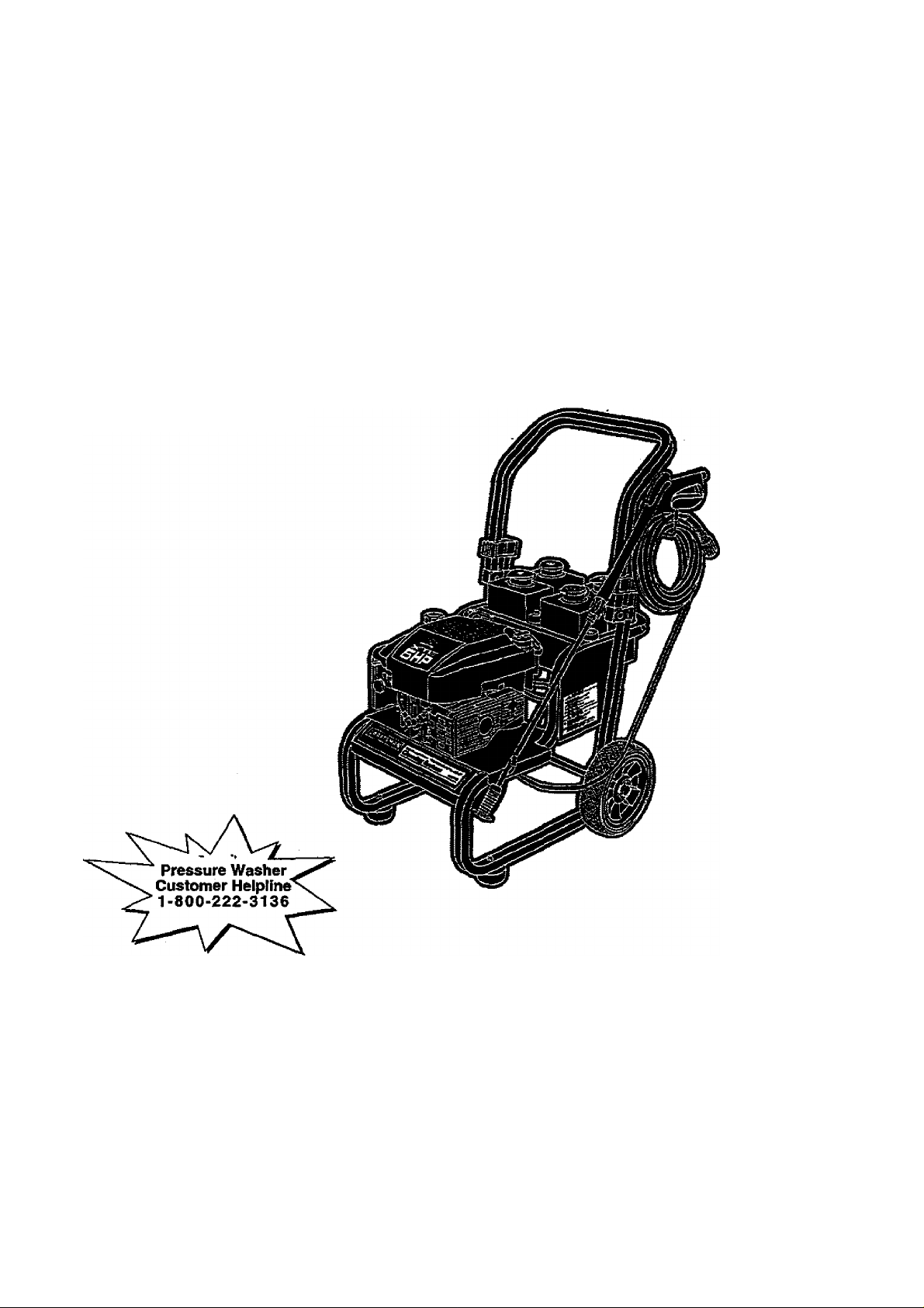
Operators Manual
CRRFTSMRN
6 Horsepower
2000 PSI
2.0 GPM
HIGH PRESSURE WASHER CLEANING SYSTEM
Model No. 580.768020
HOURS: Mon. - FrL 8 a.m. to 5 p.m. (CT)
CAUTION:
Before using this product, read this
manuai and follow all its Safety Ruies
and Operating instructions.
Sears, Roebuck and Co., Hoffman Estates, IL 60179
Visit our Craftsman website: www.sears.com/craftsman
Part No. B3639 Draft 1 (4/6/1999) Printed in the U.SA
• Safety
• Assembly
• Operation
• Maintenance
• Parts
Page 2

TABLE OF CONTENTS
Warranty
Safety Rules
Assembly...............................................................4
Operation............................................................ 5-8
Maintenance .....................................................9-12
Storage
................................................................
.......................................................
................................................................
2-3
13
2
Troubleshooting
Replacements parts
Emissions Control Warranty
How to order parts and
request service
...................................................
........................................
.......................................
............................
Back page
16-23
24-25
WARRANTY
LIMITED ONE YEAR WARRANTY ON CRAFTSMAN HIGH PRESSURE WASHER
For one year from the date of purchase, when this Craftsman Cleaning System is maintained and operated
according to the instructions in the owner's manual, Sears will repair, free of charge, any defect in material and
workmanship.
If this washer is used for commercial purposes, this warranty applies for only 90 days from the date of
purchase. If this high pressure washer is used for rental purposes, this warranty applies for only 30 days after
date of purchase. ''
This warranty does not coven
• Expendable items such as spark plugs or air filters, which become worn during normal use.
• Repairs necessary because of oper§iior abuse or negligence, including damage resulting from no water
being supplied to pump or'failure to maintain the equipment according to the instructions contained in the
owner's manual.
WARRANTY SERVICE IS AVAILABLE BY RETURNING THE HIGH PRESSURE WASHER TO THE
NEAREST SEARS SERVICE CENTER OR DEALER IN THE UNITED STATES.
This warranty gives you specific legal rights and you may also have other rights, which vary from state to state.
14
Sears, Roebuck and Co., Dept. 81 TWA, Hoffman Estates, IL 60179
SAFETY INSTRUCTIONS
0 WARNING: 0
The engine exhaust from this product
contains chemicals known to the State
of California to cause cancer, birth
defects, or other reproductive harm.
CAUTION: Before using this product, read this
A
A
manual and follow all Safety Rules and
Operating Instructions. ‘
DANGER: When transporting, setting up,
adjusting or making repairs to your cleaning
system, always disconnect the spark plug wire
and place it where it cannot contact the spark
plug to prevent accidental starting.
Engine exhaust gases contain DEADLY carbon
monoxide gas. This dangerous gas, if breathed in
sufficient concentrations, can cause
unconsciousness or even death. Operate this
equipment only in the open air wherp adequate
ventilation is available.
Gasoline is highly FLAMMABLE and its vapors are
EXPLOSIVE. Do not permit smoking, open flames,
sparks or heat in the vicinity while handling
gasoline. Avoid spilling gasoline on a hot engine.
Allow unit to cool for 2 minutes before refueling.
Comply with all laws regulating storage and
handling of gasoline.
Locate this cleaning system in areas away from
combustible materials, combustible fumes or dust.
The high pressure equipment is designed to be
used with Sears authorized parts only. If you use
this equipment with parts that do not comply with
minimum specifications, the user assumes all risks
and liabilities.
Some chemicals or detergents may be harmful if
inhaled or ingested, causing severe nausea,
fainting or poisoning. The harmful elements may
cause property damage or severe injury.
Do not allow CHILDREN to operate the cleaning
system at any time.
Page 3

Operate engine only at governed speed. Running
the engine at excessive speeds Increases the
hazard of personal injury. Do not tamper with parts
which may increase or decrease the governed
speed.
Do not wear loose clothing, jewelry or anything
that may be caught in the starter or other rotating
parts.
Before starting the cleaning system in cold
weather, check all parts of the equipment and be
sure ice has not formed there.
Units with broken or missing parts, or without
protective housing or covers should NEVER be
operated. ’ ►
The muffler and air cleaner must be installed and
in good condition before operating the cleaning
system. These components act as spark arrestors
if the engine backfires. .
Check the fuel system for leaks or signs of
deterioration such as chafed or spongy hose,
loose or missing clamps or dimaged tank or cap.
Correct all defects before operating the cleaning
.system.
Do not spray flammable liquids.
Never allow any part of the body to come in
contact with the fluid stream. DO NQT come in
contact with a fluid stream created by a leak in the
high pressure hose.
High pressure streams of fluid this equipment
produces can pierce skin and its underlying
tissues, leading to serious injury and possible
amputation. ’
Never aim the gun at people, animats or plants.
High pressure spray can cause paint chips or
other particles to become airborne and fly at high
speeds.
Always wear eye protection when you use this
equipment or when you are in the vicinity where
the equipment is in use.
Operate the pressure at no more than the PSI fluid
pressure rated for.your cleaning system.
Never move the machine by pulling on the high
pressure hose. Use the handle provided on the
top of the unit.
Always be certain the spray gun, nozzles and
accessories are correctly attached.
Never use a spray gun which does not have a
trigger lock or trigger guard in place and in
working order.
Use a respirator or mask whenever there is a
chance that vapors may be inhaled. Read all
instmctions with the mask so you are certain the
mask will provide the necessary protection against
inhaling hamriful vapors.
High pressure spray may damage fragile items
including glass. Do not point spray gun at glass
when in the jet spray mode.
Keep the hose connected to machine or the spray
gun while the system is pressurized.
Disconnecting the hose while the unit is
pressurized is dangerous.
Hold the spray gun firmly in your hand before you
start the unit. Failure to do so could result in an
injury from a whipping spray gun. Do not leave the
spray gun unattended while the machine is
running.
The cleaning area should have adequate slt^s
and drainage to reduce the possibility of a fall due
to slippery surfaces.
Keep water spray away from electric wiring or fatal
electric shock may result.
Do not secure trigger gun in the pull-back (open)
position.
Do not by-pass any safety device on this machine.
The muffler and engine heat up during operation
and remain hot immediately after shutting it down.
Avoid contact with a hot muffler or engine or you
could be severely burned.
Operate and store this unit on a stable surface.
Always store cleaning system with the
Dial-^-Cleaner™ knob in the OFF position.
High pressure hose can develop leaks from wear,
kinking, abuse, etc. Water spraying from a teak is
capable of injecting material into skin. Inspect
hose each time before using it. Check ail hoses for
cuts, leaks, abrasions or bulging of cover, or
damage or movement of couplings. If any of these
conditions exist, replace hose immediately. Never
repair high pressure hose. Replace it with another
hose that meets minimum pressure rating of your
cleaning system.
A
LOOK FOR THIS SYMBOL TO POINT OUT IMPORTANT SAFETY PRECAUTIONS.
MEANS “ATTENTION!!! BECOME ALERT!!! YOUR SAFETY IS INVOLVED.”
IT
Page 4
ASSEMBLY
CARTON CONTENTS
The following parts are shipped loose with your
cleaning system:
• Main Unit — pressure washer with wheels,
chemical tanks, guide handle.
• High Pressure Hose
• Parts Box (which includes items listed below)
• Spray Gun
• Wand Extension with Hi/Lo Adjustable Nozzle
• Engine Oil .
• Three-pack of chemical concentrates '
• Manual Bag (which includes the items listed
below) <
. • Owner’s Manual
• Nozzle Cleaner Kit
• “0”-Ring Kit
• Tank Labels j
Become familiar with each piece before assembling
the cleaning system. Check all contents against the
Illustration on Page 5. If any parts are missing or
damaged, call the Pressure Washer'Helplioe.^t^ •
1-800-222-3136. ' - ' '
TO REMOVE PRESSURE WASHER FROM
CARTON
• Remove loose parts and parts box included with
your cleaning system.
• Slice two comers at guide handle end of carton
from top to bottom so the panel can be folded .
down flat.
■ Raise guide handle, secure in place.
• Roll the cleaning system out the open end of the
carton.
• Check carton for additional loose parts.
HOW TO SET UP YOUR PRESSURE
WASHER
For the most part, your Craftsman High Pressure
Cleaning System has been assembled at the factory.
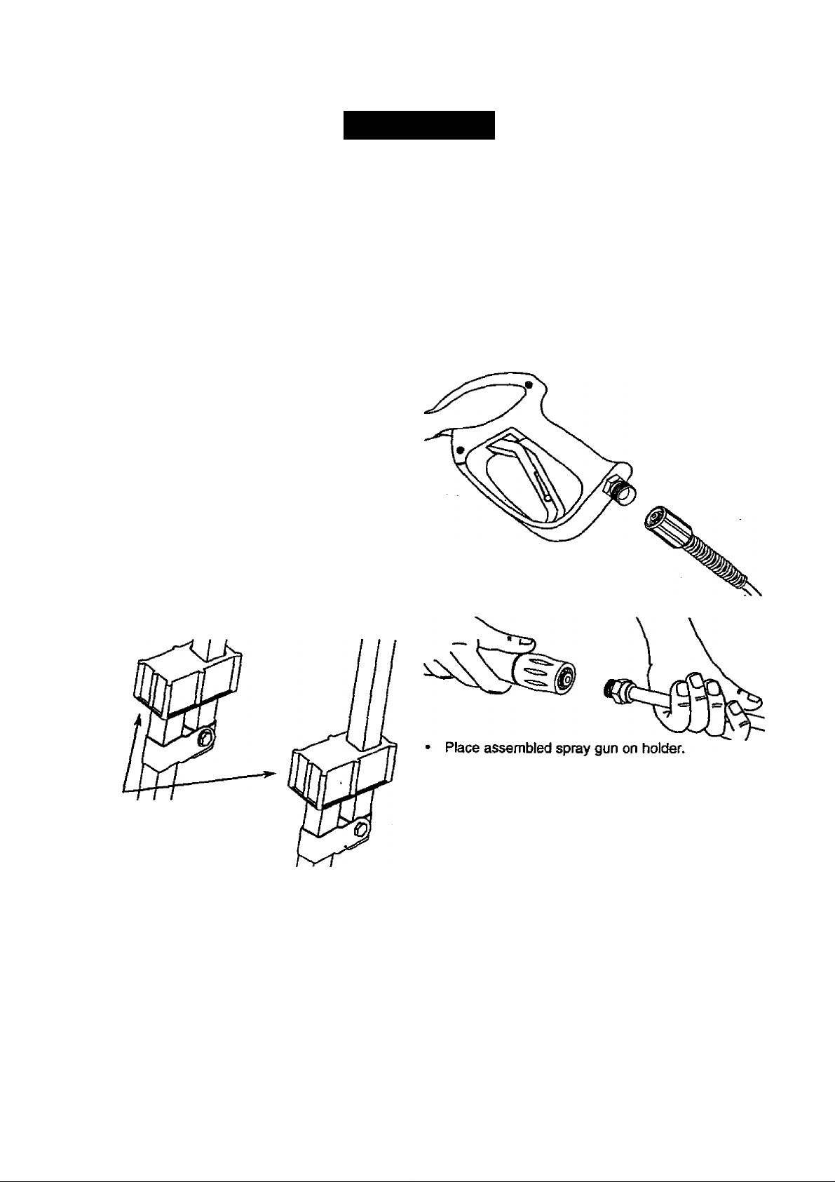
You must, however, assemble the spray gun and attach
the high pressure hose to the spray gun.
• Cut the tie wraps on the high pressure hose and
connect high pressure hose to gun. Tighten by hand.
Attach nozzle extension to spray gun.
Lift the handle to
upright position and
slide the locking
caps into place
Page 5
OPERATION
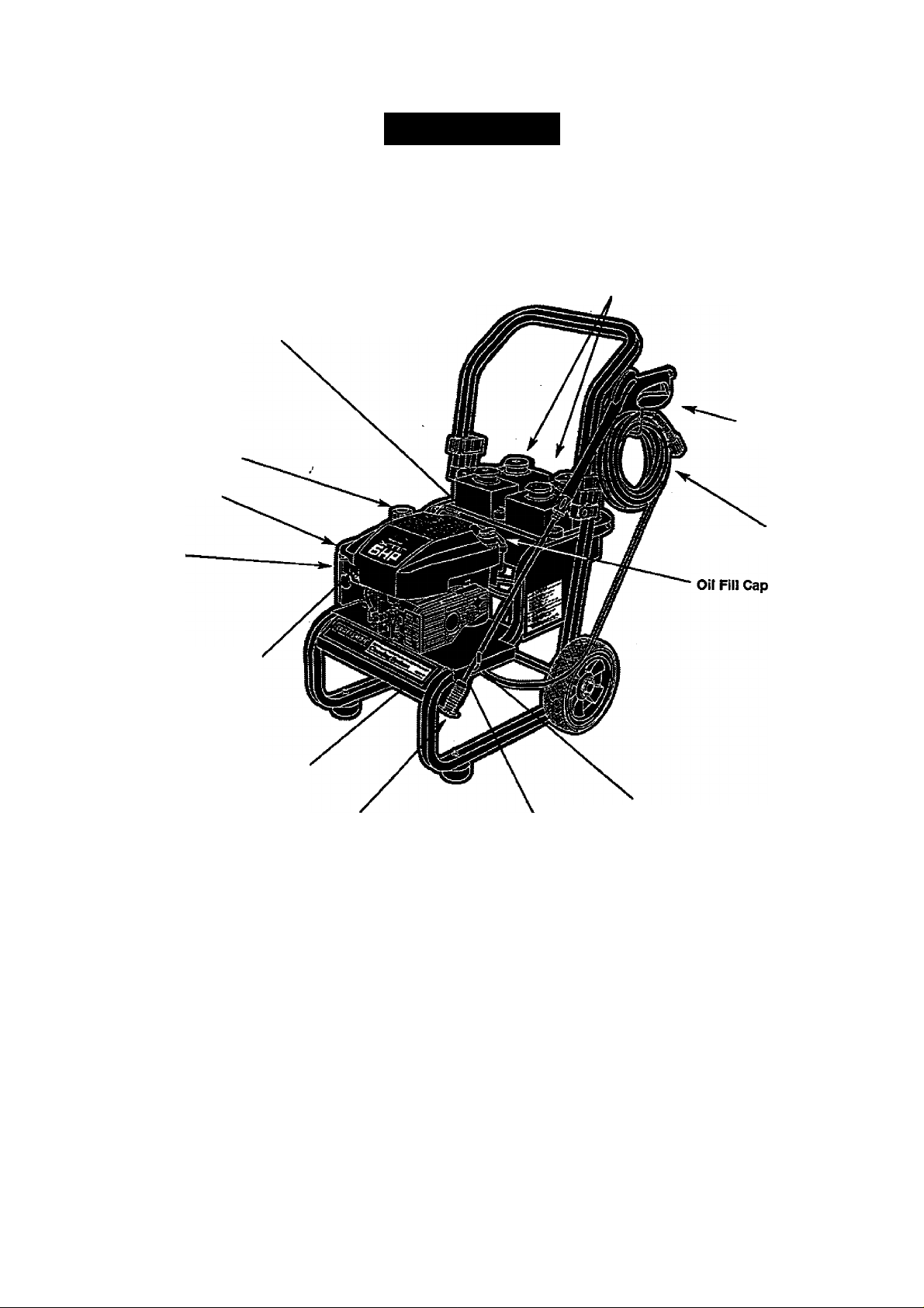
KNOW YOUR HIGH PRESSURE WASHER
Read this owner’s manual and safety rules before operating your cleaning system. Ctompare the
illustrations with your cleaning system to familiarize yourself with the locations of various controls and
adjustments.
System Rinse, Detergent and
Chemical Reservoirs with
Intemai Filter and Baffle
Dial-A-Cieaner''*'
Selector Knob
Spray Gun
Gas Cap
Throttle Control
High Pressure Hose
Air Filter
Choke Lever
Water Inlet
Adjustable Nozzle
Adjustable Nozzle - Adjust for high or low pressure;
narrow or fan spray.
Air Filter - Dry type filter element limits the amount of
dirt and dust that gets in the engine. *
Choke Lever - Used to start a cold engine.
Dial-A-Cleaner™ Selector Knob - Selects any one
of three chemicals or the clean water system rinse.
Gas Cap - Rll engine with regular unleaded gasoline
here.
High Pressure Hose - Connect one end to the spray
gun and the other to the high pressure outlet.
High Pressure Outlet - Connection for'high pressure
hose.
High Pressure Outlet
Pump
Oil Fill Cap - Fill engine with oil here. See page 7 for
oil recommendations.
Pump - Develops high pressure water.
Spray Gun - Controls the application of water onto
cleaning surface with trigger device. Includes safety
latch.
System Rinse, Detergent and Chemical Reservoirs
with Internal Filter and Baffle - Used to provide
detergent or other chemicals to the low pressure water
stream.
Throttle Control - Use to set the engine in starting
mode. Stops a running engine.
Water Inlet - Connection for garden hose.
Page 6
HOW TO USE YOUR CLEANING SYSTEM
Read these instructions and learn how to use your
cleaning system before you attempt to start your
cleaning system, if you have any problems operating
your cleaning system, please call the pressure washer
helpline at 1-800-222-3136.
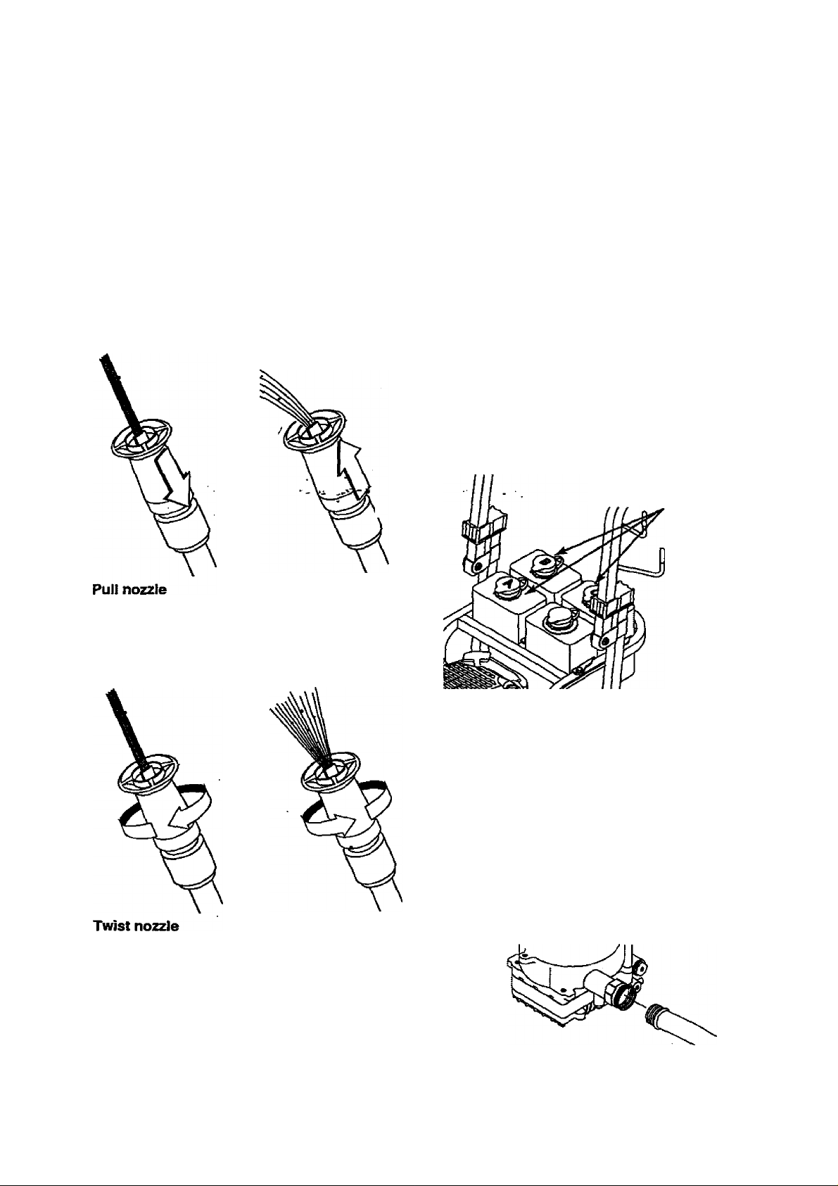
How To Use the Adjustable Nozde
WARNING! Never adjust spray pattern when
spraying. Never put hands in front of the nozzle
A
when adjusting the spray.
Push the nozzle forward for low pressure . Pull the
nozzle backward until it “snaps" into placelo
achieve high pressure.
Cleaning With The Adjustable Nozzle
CAUTION: Before starting your Cleaning
A
IMPORTANT: Use soaps designed specifically for
pressure washer cleaning systems. Household
detergents could damage the pump.
IMPORTANT: You must attach all hoses before you
start the engine. Starting the engine without all the
hoses connected and without the water turned ON will
damage the pump.
Up to three (3) different solutions can be carried on
the cleaning system at one time. To apply detergent
follow these steps:
• Dilution is necessary when using the supplied
System, make sure you have read and followed
the instmctions in the sections “Before Starting
the Cleaning System” on page 7 and To Start
the Cleaning System” on page 8.
chemical packets. Simply snip one comer of the
plastic pouch, pour the chemical into the tank, then
fill the tank with clean water. Label tanks with the
provided tank labels
Pour chemical into one of
the tanks labeled A, B, C.
Push nozzle forward
backward for high
pressure.
Twisting the nozzle adjusts the spray pattern from a
narrow to a “fan" pattern.
clockwise for
narrow spray.
For most effective cleaning, keep spray nozzle
between 8 to 24 inches away from cleaning
surface.
Damage to the surface may occur if you get the
spray nozzle too close to it.
for low pressure.
Twist nozzle
counterclockwise for
“fan” pattern.
If using another chemical designed for use with
pressure washers, prepare the chemical solution as
required by the chemical manufacturer. Rll
chemical reservoir(s) with the prepared solution as
needed.
Rotate the Dial-A-Cleaner™ selector knob to the
letter corresponding to the desired reservoir.
Push the adjustable nozzle forward to low pressure
mode. Detergent cannot be applied with nozzle
in high pressure position.
Review the use of the adjustable nozzle.
Connect garden hose to water inlet, check that high
pressure hose is connected to spray gun and pump
(see ASSEMBLY on page 4), and start engine.
Page 7

WARNING: Be extremely careful if you must
A
• Start at lower portion of area to be washed and
• Allow detergent to 'soak in’ (between 3-5 minutes)
Wash and Rinse Surface
After you have applied detergent, scour the surface
with the high pressure water stream and then rinse it
clean, as follows: -
• Pull adjustable nozzle backward to get high
• Expand the spray pattern for a more gentle rinsing
use the cleaning system from a ladder,
scaffolding or any other relatively unstable
location. When you press the trigger, the recoil
from the initial spray could force you to fall, or if
you are too close to the cleaning surface, high
pressure could force you off a climbing
apparatus.
work upward, using long, even overlapping strokes.
before washing and rinsing. Reapply as needed to
prevent surface from drying.
pressure mode. Chemical will not flow when in the
high pressure mode.
action. Start at top of area to be rinsed, working
down with same action as for cleaning.
CAUTION! Test a small area of the surface to
A
RINSE SYSTEM AFTER EVERY USE
It is imperative that the chemical selector system be
rinsed after each use to prevent clogging or leaks: >
• Fill the System Rinse reservoir with clean water.
• Before disconnecting the water supply, start your
be cleaned. Make sure there is rto damage
caused by the high pressure spray.
cleaning system.
CAUTION: Before starting your Cleaning
System, make sure you have read and followed
the instructions in the sections "Before Starting
the Cleaning System" on page 7 and To Start
the Cleaning System” on page 8.
Push adjustable nozzle forward to get low pressure
mode.
Rotate the Dial-A-Cleaner™ selector knob to the
letter corresponding to the System Rinse tank. As
clean rinse water is drawn through the system,
continue the flow until no detergent foam is
observed.
Rotate the Dial-A-Cleaner'^** selector knob to the
OFF position.
*
BEFORE STARTING THE CLEANING SYSTEM
To operate the engine you will need to do the following:
Add Engine Oil
Only use high quality detergent oil rated with API
service classification SF or SG. Select the oil’s SAE
viscosity grade according to your expected operating
temperature:
colder ^111 !■ 32°F ■!! » warmer
5W30
Although multi-viscosity oils (5W30,10W30, etc.)
improve starting in cold weather, these multi-viscosity
oils will result in increased oil consumption when used
above 32°F. Check your engine oil level more
frequently to avoid possible damage from running low
on oil.
• Place pressure washer system on a level surface
• Clean area around oil fill and remove oil dipstick.
• Wipe dipstick clean.
• Pour oil from enclosed bottle Into the oil fill opening
until oil reaches full mark on the dipstick. Stop and
check the oil level periodically. Do not overfill.
• Install oil dipstick, hand tighten securely.
Add Gasoline
• Use regular unleaded gasoline with the cieaning
system engine. Fuel tank capacity is 1.5 U.S.
quarts.
DANGER! Never fill fuel tank indoors. Never
A
A
A
To add fuel to engine:
• Clean area around fuel cap, remove cap.
• Add regular unleaded gasoline, slowly, to the fuel
Important: Never mix oil with gasoline.
• Install fuel cap and wipe up any spilled gasoline.
fill fuel tank when engine is running or hot. Do
not smoke when filling fuel tank.
CAUTION! Do not overfill the fuel tank.
Always leave room for expansion.
CAUTION! Experience indicates that alcohoi
blended fuels (called gasohol or using ethanol
or methanol) can attract moisture which leads
to separation and formation of acids during
storage. Acidic gas can damage the fuel
system of an engine while in storage.
tank.
SAE 30
Page 8
TO START YOUR PRESSURE WASHER
The best way to start your cleaning system engine for
the first time is to follow these instructions step-by
step. This starting information also applies whenever
you start the engine after you have let the cleaning
system sit idle for at least a day.
• Place the cleaning system in an area close enough
to an outside water source that can flow at a rate of
at ieast 2.5 galions per minute. Connect a garden
hose to the water spout.
• Check that the high pressure hose is lightly
connected to the spray gun and to the pump. See
ASSEMBLY section on page 4. ■,
• Check inlet screen on the water inlet. If the screen
is dirty, clean before attaching a garden hose. If the
screen is damaged, do not connect to the garden
' hose. Replace with screen provided in maintenance
kit or call 1-800-366-PART to order a replacement
inlet screen.
• Attach the the garden hose to the water inlet.
• Turn on the water.
Important: Do not run pump without the water supply
connected and turned on. You must follov/this ca.ution
or the pump will be damaged.- - ’ ' '' r''
• Remove the adjustable nozzle extension from the
spray gun.
• Pull the trigger on the spray gun and hold until a
steady stream of water flows from the gun.
• Engage the safety latch on the spray gun.
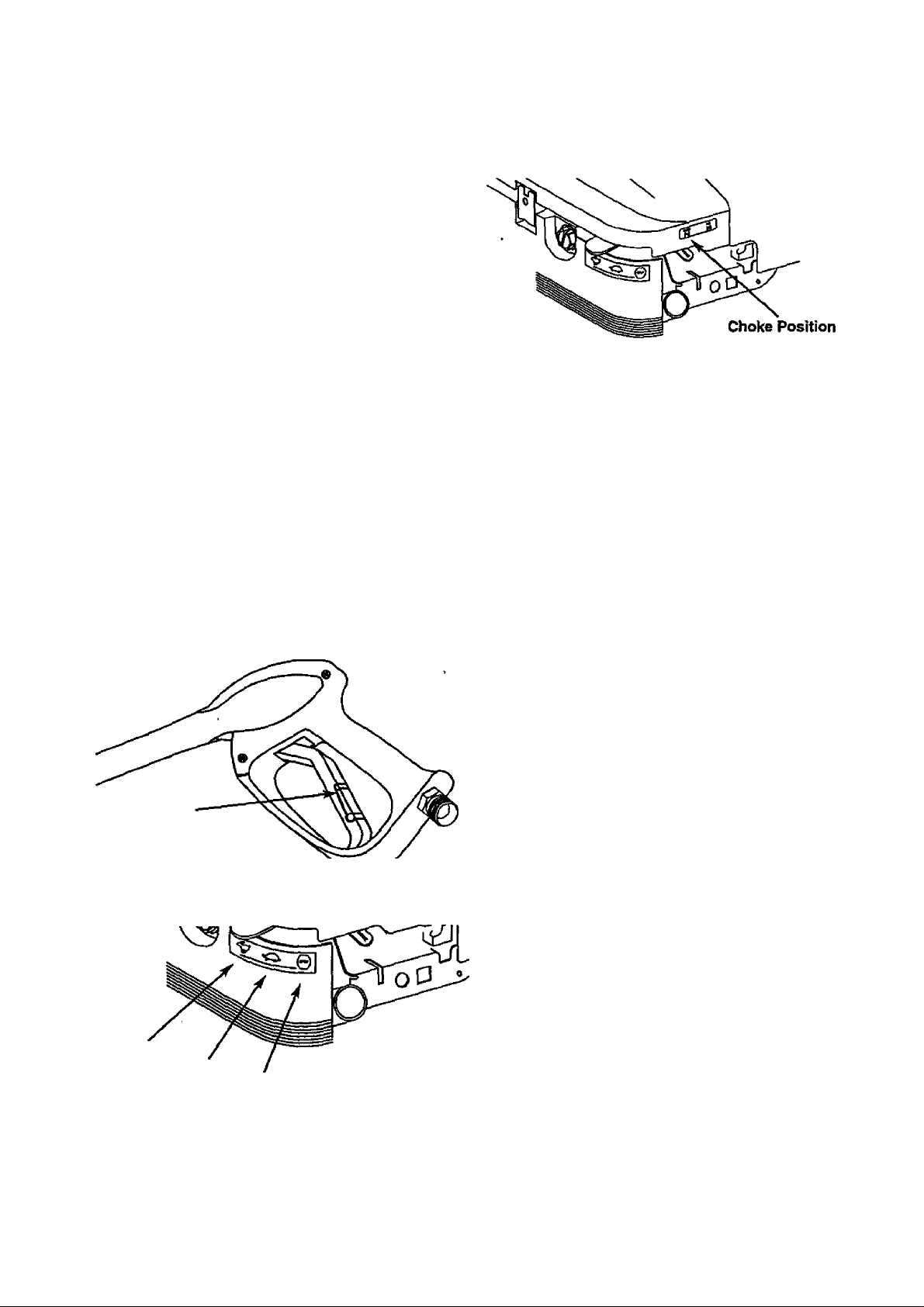
Safety Latch
Attach adjustable nozzle extension onto spray gun.
Move the throttle control lever to the “Fast”
position.
Note: If restarting a warm engine after a short
shutdown, be sure the throttle control is in the "Fast”
position and the choke is in the “Run” position.
• Grasp rope handle and pull slowly until you feel
some resistance. Then pull cord rapidly to
overcome compression, prevent kicldiack and start
the engine. Let rope return to starter slowly.
Note; Always keep the Throttle Control Lever in the
‘Fast* position when operating the pressure washer.
• When the engine starts, gradually move the Choke
Lever from one position to the next until it is in the
“Run” position.
Note: If after 3 pulls the engine fails to start, move the
Choke Lever to the ‘Run’ position, pull trigger on gun
to relieve pressure, reengage safety latch, and puli the
recoil starter handle rapidly (Max. 3 pulls).
• Once the engine has started, disengage the spray
gun safety latch.
HOW TO STOP YOUR PRESSURE
WASHER
Important Do not run pump without the water supply
connected and turned on. You must follow this caution
or the pump will be damaged.
• Move the Throttle Control Lever to the ‘Stop’
position.
• Simply shutting off the engine will not release
pressure In the system. Squeeze trigger on the
spray gun to relieve pressure in the hose.
Note: A small amount of water will squirt out when you
release the pressure.
• Rotate the Dial-A'Cleaner^^ selector knob to the
OFF position to prevent chemical leakage.
SIPHONING
DO NOT siphon standing water for your water supply.
Contaminated, brackish or dirty water can damage the
pump. Connect only to household water supply.
Fast
Slow
Stop
Set the choke lever to “Choke” position.
TIPS
• Never use the garden hose inlet to siphon
detergent or wax.
• If you hold the spray nozzle too far away from the
object being cleaned, washing will not be as
effective.
• Always store the cleaning system vwth the Dial-/
Cleaner™ selector knob to the OFF position.
8
Page 9

MAINTENANCE
CUSTOMER RESPONSIBILITIES
MAtlTTENANCE SCHEDULE
FILL IN DATES AS YOU COMPLETE
REGULAR SERVICE
MAINTENANCE TASK
PRESSURE WASHER
Chack/dean water inlet screen
on quick-connect.
Check high pressure hose.
Check detergent hose.
Check spray gun and assembly for leaks.
Purge purr^} of air and contaminants.
ENGINE
Check oil level.
Change engine oil. /
Service air deaner.
ClearVreplace spark plug.
Prepare for storage.
t Clean if clogged. Replace if perforated or tor^.
• Change oil after the first (2) operating hours and every 50 hours thereafter. Change sooner whw> operating under dirty or dusty
conditirxis.
** Replace more often under dirty or dusty conditions.
HOUP
[LY OPER/
tTlNG
INTERVAL
Belore Each
Use
xt
X .
X
X
X
X
Prepare unit for storage if it is to
remain ¡die for longer than 30 days.
Every so
Hours or
Yearly
X*
Every 100
Hours or
Yearly
X**
X
SERVICE DATES
PRODUCT SPECIFICATIONS Pressure Washer Specifications
PRESSURE
FLOW RATE
CHEMICAL MIX
Use as directed
2000 DSi
2.0 GPM
WATER SUPPLY
TEMPERATURE
Not to Exceed 140'’F
Engine Specifications
ENGINE MODEL
Briaas & Stratton
RATED HORSEPOWER
SPARK PLUG: Type: Champion RJ-19LM
or equivalent. Set
Gap to: 0.030 inch
(0.76mm)
GASOLINE CAPACITY
OIL
SOLID STATE
1.5 U.S. Quarts
SAE 30 weiaht
0i)125inch
IGNITION AIR GAP
. 6
In the State of California a spark arrestor is required
by law (Section 4442 of the California Public
Resources Code). Other states may have similar laws.
Federal laws apply on federal lands.
Note: If you equip the engine of your cleaning system
with a spark arrestor muffler, the spark arrestor must
be maintained in effective working order by the
owner/operator.
You can order a spark arrestor through your Sears
Service Center.
GENERAL RECOMMENDATIONS
The warranty of the cleaning system does not cover
items that have been subjected to operator abuse or
negligence. To receive full value from the warranty,
operator must maintain cleaning system as instructed
in this manual.
Some adjustments will need to be made periodically to
properly maintain your cleaning system.
All adjustments in the Service and Adjustments
section of this manual should be made at least once
each season.
• Once a year you should clean or replace the spark
plug and replace the air filter and check the gun
and wand assembly for wear. A clean spark plug
and new air filter assure proper fuel-air mixture and
help your engine run better and last longer.
Page 10

BEFORE EACH USE
• Check water inlet screen for damage.
• Check high pressure hose for leaks.
• Check chemical tanks and filters for damage.
• Check gun and wand assembly for leaks.
• Purge pump of air and contaminants.
• Check engine oil level.
PRESSURE WASHER MAINTENANCE
Check and Clean Inlet Screen
Examine garden hose inlet screen. Clean if it-ig
clogged or replace tf it is tom.
Check High Pressure Hose .
fHigh pressure hoses can develop leaks from wear,
kinking, or abuse. Inspect hose before each use.
Check for cuts, leaks, abrasions, bulging of cover, or
damage or movement of couplings. If any of these
conditions exist, replace hose immediately.
DANGER; Never repair a high pressure hose.
A
Check Chemical Reservoirs
Tank covers should snap cleanly onto tank. Ensure
chemical labels correctly identify tank contents.
Ensure that the System Rinse tank is filled with clean
water. Ensure that Dial-A-Cleaner™ selector knob
rotates freely between each position. Examine the .
tanks and replace if the filter is clogged.
Check Gun and-Wand
Examine hose connection to gun and make sure it is
secure. Test trigger by pressing it and making sure it
springs back into place when you release it. Put safety
latch in UP position and test trigger. You should not be
able to press trigger. Replace gun immediately if it
fails any of these tests.
Check In-Line RIter ,
Refer to the illustration and service the in-line filter if it
becomes clogged, as follows: '
Replace with hose that meets the minimum
pressure rating of your.cleaning^systern ' -
In-line Filter
Lance
2. if the screen is damaged, the o-ring kit contains a
replacement in-line filter screen and an o-ring. If
undamaged, reuse screen.
3. Place the in-line filter screen into the threaded end
of the lance. Direction does not matter. Push the
screen in with the eraser end of a pencil until it
rests flat at the bottom of the opening. Take care to
not bend the screen.
4. Place the o-ring into the recess. Push the o-ring
snugly against the in-line filter screen.
5. Assemble the lance to the spray gun, as described
earlier in this manual.
Purge Pump of Air and Contaminants
To remove the air from the pump, follow these steps;
• Set up the cleaning system as described in the
ASSEMBLY section and connect the water supply.
• Remove the wand extension from the gun.
• Pull the trigger on the gun and hold until a steady
stream of water appears.
To remove the contaminants from the pump, follow
these steps:
• Set up. the cleaning system as described in the
ASSEMBLY section, and connect the water supply.
• Remove the nozzle attachment from the gun.
• Start the engine according to instructions in
OPERATION section.
• Pull the trigger on the gun and hold.
• When the water supply is steady and constant,
engage the safety latch and refasten the nozzle
attachment.
Nozzle Maintenance
If the nozzle becomes restricted or clogged with
foreign materials, such as dirt, excessive pump
pressure may develop. A partially clogged nozzle can
cause a pulsing condition during use. This generally is
not a pump related problem, but rather a clogged or
partially restricted nozzle.
If the nozzle becomes clogged or partially restricted,
immediately clean the nozzle with the kit included with
your cleaning system by following these instructions:
• Shut off the engine and turn off the water supply.
• Separate the wand from the gun.
• Rotate to stream setting.
• Remove nozzle from the end of the wand using a
2mm or 5/64 alien wrench.
O-ring
1. Detach gun and lance from high pressure hose.
Detach lance from gun and remove o-ring and
screen from lance. Flush the screen, gun, and
lance with clean water to clear debris.
10
Page 11

Use the wire included in the kit or a small paper
clip to free the foreign materials clogging or
restricting the nozzle.
Insert wire into nozzle and turn back and forth to
clear obstruction.
Parts in the O-Ring Kit Include:
• 1 o-ring, red, (p/n B2726) for the end of the spray
gun connection between gun and high/low spray
wand.
Remove additional debris by back flushing water
supply through wand. Back flush between 90 to 60
seconds. Turn wand to stream spray and mdve
nozzle from low to high pressure while flushing.
• Reinstall nozzle into wand. DO NOT overtighten.
• Reconnect wand extension to spray gun.
• Reconnect the water supply, turn Olj the water,
and start the engine.
• Test the cleaning system by operating with nozzle
in the high and the low pressure positions.
0-Ring Maintenance Through the normal operation of your cleaning
system, the o-rings keep the connections of the hoses
and gun tight and leak-free. They may become worn
or damaged with use. Provided with your cleaning
system is an O—ring Maintenance Kit containing
replacement o-rings, a rubber washer and a garden
hose inlet screen.
o
2 o-rings, yellow, (p/n B2264) for the ends of the
high pressure hose.
Note: The above two o-rings are close in size.
Please match carefully to assure proper o-ring
usage.
* 1 rubber washer (p/n B2385) for the inside of the
garden hose connector.
• 1 water inlet screen (p/n B2384) for the garden
hose connector.
To remove a worn or damped O-Ring:
• Use a small flathead screwdriver to get
underneath the o-ring and pry it off.
11
Page 12

ENGINE MAINTENANCE
Maintenance, replacement or repair of the
emission control devices and systems may be
performed by any non-road engine repair
establishment or individual.
Checking Oil Level
Oil level should be checked prior to each use or at
least every 5 hours of operation. Keep oil level
maintained.
Changing Oil
Change engine oil after the first 2 hours and ev^ry 50
hours thereafter. If you are using your cleaning system
under extremely dirty or dusty conditions, or in
extremely hot weather, change oil more often. ■
•Change oil while engine is still warm from running, as
follows:
• Drain fuei tank by running pressure washer until
fuel tank is empty.
• Clean area around oil fill, remove oil fill
cap/dipstick. Wipe dipstick clean.
• Tip your pressure washer to drain oil frbm Ihe.oil fill
tube into a suitable'container. When cf&tik)^se is
empty, return the pressure washer to upright
position.
• Fill engine crankcase with recommended oil until oil
level is at FULL point on dipstick. Do not overfill
above that mark. POUR SLOWLY.
• When engine crankcase is filled to proper level,
install and tighten oil cap/dipstick. '
To clean or replace the air cleaner, follow these steps:
• Remove screw on the air cleaner cover.
• Remove dirty air cleaner carefully to prevent debris
from falling into carburetor. Discard.
• Clean inside of filter case.
• Install new air filter.
• Reassemble all parts and fasten securely to the
carburetor with the screw.
Clean / Replace Spark Plug
Clean or replace the spark plug yearly or every 100
hours of operation.
CAUTION; Disconnect spark plug wire from
A
spark plug and keep wire away from spark
plug.
Clean area around spark plug.
Remove and inspect spark plug.
Replace spark plug if the electrodes are pitted,
burned or porcelain is cracked. For replacement
use Champion RJ-19LM or equivalent.
Check electrode gap with wire feeler gauge and set
gap at-.030 inches, if necessary.
Service Air Cleaner
Your engine will not run properly and may be
damaged if you run it with a dirty air cleaner.
Replace the air cleaner once every 100 hours of
operation or once each year, whichever comes first.
Replace more often if operating under dirty or dusty
conditions. Do not attempt to clean or oil filter.
Replacements are available at your local Sears
Authorized Service Center.
Carburetor
If you think your carburetor needs adjusting, see your
nearest Sears Service Center. Engine performance
may be affected at altitudes above 4000 feet. For
operation at higher elevations, contact your nearest
Sears Service Center.
12
Page 13

STORAGE
AFTER EACH USE
Water should not remain in the unit for long periods of
time. Sediments of minerals can deposit on pump
parts and “freeze” pump action. Follow these
procedures after every use:
• Flush the chemical system by selecting the System
Rinse tank and run the Pressure Washer with
nozzle in low pressure mode. Flush for one minute
or until the chemical is cleared from the system.
• Shut off the engine and let it cool, then rempve all
hoses.
CAirnON: Be sure the engine Run/Stop,switch
A
is in the ‘0’ or Stop position before you
continue. .
Empty the pump of all pumped liquids by pulling
recoii handle about 6 times wjth the Run/Stop.
switch in the ‘0’ or Stop position. This should
remove most of the liquid in the pump.
-flotate ttie Dial-A-Cleaner™ selector knob to the
OFF position.
Coil the high pressure hose and inspect it for
damage. Cuts in the hose or fraying^could result in
leaks and loss of pressure. Should any damage be
found, replace the hose. DO NOT attempt to repair
a damaged hose. Replace the hose with the
genuine Craftsman part.
Drain water from hose and properly hang it on the
wire support provided. ’
Store system in a clean, dry area.
DANGER: Never store the engine with fuel in
the gas tank indoors or in enclosed, poorly
A
ventilated areas where fumes may reach an
open flame, a spark, or pilot light.
WINTER STORAGE
CAUTION: Yojj must protect ydur unit from
freezing temperatures. Failure to do so will
A
permanently damage your pump and render
your unit inoperable.
To protect the unit from freezing temperatures:
• Empty all chemical reservoirs as follows:
a. Disconnect hose connected to chemical inject
fitting on the pump. Place end of hose into
suitable container.
b. Move the selector knob to Tank A and open
that tank’s cover. Gravity should shortly empty
the tank contents into the container.
c. When the tank is empty, repeat,step (b) for
tanks B and C.
d. Reconnect the hose to the chemical inject
fitting on the pump. Add 0.5 liter of clean fresh
water to each tank and close tank’s covers.
• Flush the chemical system by selecting a tank and
run the Pressure Washer with nozzle in low
pressure mode. Flush until each tank is empty, then
switch the selector knob to the next tank. The last
tank to be emptied must be the System Rinse tank.
• Connect a 3-foot section of garden hose to the inlet
adapter. Pour RV-Ant'rfreeze (antifreeze without
alcohol) into the hose. Pull the recoil handle twice.
LONG TERM STORAGE
If you do not plan to use the Pressure Washer for
more than 30 days, you must prepare the engine for
long term storage.
It is important to prevent gum deposits from forming in
essential fuel system parts such as the carburetor, fuel
filter, fuel hose or tank during storage. Also,
experience indicates that alcohol-blended fuels (called
gasohol, ethanol or methanol) can attract moisture
which leads to separation and formation of acids
during storage. Acidic gas can damage the fuel system
of an engine while in storage.
Protect Fuel System
DANGER: Drain fuel into approved container
A
• Remove all gasoline from the fuel tank to prevent
• Run engine until engine stops from lack of fuel.
Change Oil
While engine is stilt warm, drain oil from crankcase.
outdoors, away from open flame. Be sure
engine is cool. Do not smoke.
gum deposits from forming on these parts and
causing possible malfunction of engine.
Make sure you have water supply to pump inlet
connected and turned ON.
Refill with recommended grade. (See Changing Oil)
Oil Cylinder Bore
• Remove spark plug. Squirt about 1 ounce (30 ml) of
engine oil into the cylinder. Cover spark plug hole
with rag. Crank engine slowly to distribute oil.
CAUTION: Avoid spray from spark plug hole
A
when cranking engine.
Install spark plug. Do not connect spark plug wire.
OTHER
• Do not store gasoline from one season to another.
• If possible, store your unit indoors and cover it to
give protection from dust and dirt. BE SURE TO
EMPTY THE FUEL TANK.
IMPORTANT: NEVER cover your cleaning system
while engine and exhaust area are warm.
13
Page 14

TROUBLESHOOTING
PROBLEM
Pump has following problems:
failure to produce pressure, or
erratic pressure, chattering, loss of 2. Water inlet is blocked.
pressure, low water volume.
Detergent fails to mix. . , , ; ■ •^1 ...-Detergent line is collapsed or
CAUSE
1. Nozzle in low pressure mode.
3. Inadequate water supply
4. Inlet hose is kinked or leaking
5. Clogged water inlet screen.
»
6. Water supply is over 140°F.
7. Outlet hose is blocked.
8. Outlet hose leaks.
9. Gun leaks.
10. Nozzle is obstructed.
11. Pump is faulty.
kinked
2. Chemical tank fitter is clogged.
3. Nozzle is in high pressure mode.
4. Dial-a-Cieaner knob is in off position.
CORRECTION
1. Pull nozzle backward for high
pressure mode.
2. Clear inlet
3. Provide adequate water flow at
least 2.5 gpm.
4. Straighten inlet hose, patch leak.
5. Replace / clean water inlet
screen.
6. Provide cooler water supply.
7. Clear blocks in outlet hose.
8. Replace outlet hose if leaking.
9. Replace O-ring or gun if
rtecessary.
10. Clear nozzle.
11. Contact Sears Service
Department
1. Repair or replace detergent
line.
2. Replace tank
3. Push nozzle forward for
low pressure mode.
4. Rotate knob for desired chemical.
Engine runs good when not spraying
but dies when you begin to spray.
Engine will not start; or starts
and runs rough
Engine shute down during
operation 2. Air filter dirty
Engine lacks power.
Engine speed is too slow.
1. Ditty air cleaner
2. Out of gasoline.
3. Stale gasoline.
4. Spark plug wire not connected
to spark plug.
5. Bad spark plug.
6. Vifater in gasoline.
7. Overchoking or flooded
8. Excessively rich fuel mixture.
9. Intake valve stuck open or closed.
10. Engine has lost compression.
1. Out of gasoline.
Dirty sdr filter.
Contact Sears Service D^artment
1. Clean or replace air cleaner.
2. Rll fuel tank.
3. Drain gas tank; fjil with fresh fuel.
4. Connect wire to spark plug.
5. Replace spark plug.
6. Drain gas tank; fill with fresh fuel.
7. Set engine throttle control lever to
fast position, choke in run
position.
8. Contact Sears Service
Department.
9. Contact Sears Service
Department.
10. Contact Sears Service
Department.
1. Rll fuel tank.
2. Replace Air filter.
Replace air filter.
14
Page 15

NOTES
15
Page 16

PARTS
Craftsman 2000 PSI Cleaning System 580.768020
Briggs & Stratton 6HP Quantum #12H802-2383-E1
16
Page 17

Craftsman 2000 PSI Cleaning System 580.768020
Briggs & Stratton 6HP Quantum #12H802-2383~E1
847
523
177 CD
17
Page 18

Craftsman 2000 PSI Cleaning System 580.768020
Briggs & Stratton 6HP Quantum #12H802-2383>E1
Item
1
2
3
4 493279
5
7
8 495786
9
10 691125
11 691781
12
13 94547 Screw (Cylinder Head)
15 94720
16 498565
20
22
22
22 94612
23 691992
24
25 499429
25
25
25 499431
25
26 499425
26 499426
26
26 499428 Ring Set (.030" O.S.)
27 263190
28 499423
29 499424 Rod-Connecting
32
33
34
35
37
40
43
Part#
Kit
493260
293708
299819
t
214368
272916
t+
272481
t+
272198
t
399781 Seal-Oil
t
94220
222698
499430
499432
499427. Ring Set (.020" O.S.)
94699
262651
262652
262224
224511
93312 Retainer-Valve
493737
Description
Cylinder Assembly
Bushing/Seal Kit
Seal-Oil 51
Sump-Engine 54
Head-Cylinder
Gasket-Cylinder Head
Breather Assembly
Gasket-Breather
Screw (Breather Assembly)
Tube-Breather
Gasket-Crankcase ,
Plug-Oil Drain -
Crankshaft
Screw (Engine Sump)
--------Screw (One Used in Hole
Nearest Breàther)'..,
■ Flywheel ' r' '
Key-Flywheel
Piston Assembly (Standard)
---------
Piston Assy. (.010’ O.S.)
Piston Assy. (.020" O.S.)
Piston Assy. (.030’ O.S.)
Ring Set (Standard) ’
Ring Set (.010’ O.S.)
Lock-Piston Pin
Pin-Piston
Screw (Connecting Rod)
Valve-Exhaust
Valve-Intake .
Spring-Valve ■
Guard-Flywheel
Govemor/Oil Stinger
Note
Note
--------
--------
Item
Ki!
45
46
t
55
56
58
60
65A
78
81
95
104
108
109
110
117
121
125
130
131
133
134
137
146
159
163 ti¥
177
187
190
202
209
222
227
287
300
304
Part#
262204 Tappet-Valve
498275
272199 Gasket-Intake
94526
497440 Housing-Rewind Starter
498144 Pulley-Starter
280399
281434
94686 Screw (Rewind Starter
691108 Screw (Flywheel Guard)
223664 Lock-Muffler Screw
94098 Screw (Throttle Valve)
231371 Pin-Float Hinge
+
223471 Valve-Choke
498593 Choke Shaft Kit
498478 Jet-Main
498260
499059 Carburetor
224908
493267 Shaft-Throttle
398187
398188 Valve-Needle (Includes Seat)
t
Pf
94388 Key-Timing
224815 Bracket-Support
272653
280393
t
492790
94511 Screw (Fuel Tank)
262579 Link-Mechanical Governor
693187
692150
492349
94511 Screw (Oil Fill Tube)
497838 Muffler-Exhaust
493294
Description
Gear-Cam
Screw (Intake Manifold)
Rope-Starter (Cut to Required
Length)
Grip-Starter Rope
Housing)
Washer (Sold in Kit Only)
Carburetor Kit
Valve-Throttle
Float-Carburetor
Gasket-Float Bowl (Sold in Kit
Only)
Gasket-Air Cleaner
Seal-O-Ring
Line-Fuel (Molded)
Spring-Governor
Bracket-Control
Lever-Governor
Housing-Blower
18
Page 19

Craftsman 2000 PSI Cleaning System 580.768020
Briggs & Stratton 6HP Quantum #12H802-2383-E1
Part# Description
Kit
Item
t
t
691108
224324
94515
690662
802574
94731
802592
497833
497316
19069
94525
92987
89838
67072
94872
692523
491588
225121
281503
281505
495264
495265
281299
92613
224328
272238
231082
94943
93053
497680
94231
94474
263175
270344
262749
396847
497465
493823
305
306
307
332
333
334
337
356
358
363
365
373
383
404
425
443
445
455
456
459
523
525
529
562
584
585
592
597
601
608
613
615
616
617
618
621
625
635 66538
668
670 280512
Item Kit
Screw (Blower Housing)
Shield-Cylinder
Screw (Cylinder Shield)
Nut (Flywheel)
Armature-Magneto
Screw (Magneto Armature) 832
Plug-Spark
Wire-Stop
Gasket Set •,
Flywheel-Puller
Screw (Carburetor)
Nut (Rewind Starter Housing)
Wrench-Spark Plug
Washer (Governor Crank)
Screw (Air Cleaner Cover) 871
Screw (Interlock Switch)
Filter-A/C Cartridge
Cup-Flywheel
Plate-Pawl Friction
Pawl-Ratchet
Dipstick
Tube-Oil nil '
Grommet
Bolt (Governor Lever)
Breather Passage Cover
Gasket-Breather Passage
Nut (Governor Lever) ,
Screw (Pawl Friction Plate)
Clamp-Fuel Line
Starter-Rewind
Screw (Exhaust Muffler)
Retainer
Crank-Governor 1087 t
Seal-Intake Manifold
Spring
Switch-Stop
Manifold-Intake
Boot-Spark Plug
Spacer (Includes 2)
Spacer-Fuel Tank
687 .
689A
692
741
836
843
847
851
869
870
871
871
921
957
959
966
967
968
969
970
972
975
976
977
1019
1036
1058
1059
1095
1102
t Included in Gasket Set, Ref Number 358.
t Included in Carburetor Kit, Ref Number 121.
¥ Included in Carburetor Gasket Set, Ref Number 977.
+ Included in Value Overhaul Kit, Ref Number 1095.
Part#
94515
263073
262715
262598
499034
49874
272616
495263
493880
213512 Seat-Valve (Intake)
213513
262001
63709
497233
397974
690877
496116
493537
281340
94696
94749
495224
493640
496115
498261
494256
499341
273693
398540
280966
498528
232153
Description
Screw (Breather Passage
Cover)
Spring-Friction
Spring-Detent
Gear-Timing
Guard-Muffler
Screw (Muffler Guard)
Steeve-Lever
Dipstick/Tube Assembly
Terminal-Cable
Seat-Valve (Exhaust)
Bushing-Guide
(Exhaust Valve)
----------Note
Bushing-Guide (Intake Valve)
Cover-Blower Housing
Cap-Fuel Tank
Screw (Control Bracket)
Base-A/C Primer
Filter-Pre Cleaner
Cover-Air Cleaner
Screw (Blower Housing Cover)
Screw (Support Bracket)
Tank-Fuel
Bowl-Float
Primer-Carburetor
Gasket Set-Carburetor
Label Kit
Label Kit-Emission
Owner’s Manual
Screw/Washer Kit
Seal-O-Ring
Gasket Set-Valve Overhaul
Pilot-Guide
--------
19
Page 20

Craftsman 2000 PSI Cleaning System 580.768020
Pump
38
39
30 31
/
uo
32
20
Page 21

Craftsman 2000 PSI Cleaning System 580.768020
Pump
Item
1
2
3
4
5
6
7
10
11
12
13
14
15
16
17
18
19
20
21
22
23
24
25
26
Part#
98300
97962
96795
21429
97835
21783
Qtv
1
3
3
6
1
1
Description
SEAL, Engine Donut
SHCS, M6 • 1 X 25
SLEEVE, Grommet
Spacer
BUSHING, Rubber
Mount
O-RING, Housing Seal
THERMAL RELIEF,
Item
27
28
29
30
31
32
33
34
Part# Qtv
1
1
1
B3513
0
6
6
B3286
97837
3
1
GPW'EG ■ .
93680
3
SEAL, Oil Piston 15
35
97841
3
TC4
8
9
97831
B2702
98227
B2310
3
1
1
0
SPACER, Pilot'
HOUSING, Piston
ADAPTER, Engine
KIT, AXIAL CAM
36
37
38
97840 3
40946
B4186
4
0
SERV ■
1
1
WASHER. Brg. 36 x 65
X 6Thk
ASSY., Brg. Cage 45 x
39
40
41
B2312
1
1
0
65
3
3
3
0
1
1
3
1
1
1
3
3
B3829
B3828
1
1
1
WASHER, Brg. 45 x 65
Xl ^
CAM, Axial 5.6 VS
BALL BEARING, 35 x
72x17
0
1
1
1
1
1
0
1
1
1
KIT, CHEM INJECT
FITTING, Chem Inject
BALL, Chem Inject
SPRING, Chem Inject
O-RING, Venturi
VENTURI, Chem Inject
KIT, UNLOADER
CAP, Unloader
O-RING, Unloader Cap
SPRING, 2000
Unloader
42
43
44
45
21
25
28
33
B1933
1
5
7
34
Description
PISTON. Unloader
O-RING, .364 ID x .070
SEAT, 2000 Unloader
KIT, CHECK VALVES
O-RlNG, Check Valve
ASSY., Check Valve
SEAL, Double-Up
O-RING, H¡-Pressure
Transfer
CAP, Outlet Check
Valve
O-RING, Outlet CV
Cap
SHCS, M6-1.0 X 35
KIT, HEAD CASTING
SFG
HEAD, Pump
PLUG, 1/8-28 W/VIRB
KIT, PISTON &
SPRING
RETAINER, Piston
Spring
PISTON, Dia. 15 x 65
Lg
SPRING, Piston Return
KIT, O-RING/SEAL
SERV
SEAL, Engine Donut
O-RING, Housing Seal
SEAL, Oil Piston 15
TC4
O-RING, Venturi
O-RING, Unloader Cap
O-RING, .364ID X .070
SEAL, Double-Lip
O-RING, Outlet CV Cap
21
Page 22

Craftsman 2000 PSl Cleaning System 580.768020
Main Unit
22
Page 23

Craftsman 2000 PSI Cleaning System 580.768020
Main Unit
Description
Part# (
item
48031C
2
EB3637
3
B3615
4
B4141
5
B3377 3 SCREW, Plastite8-11 3/4*
6
B3721
7
B3311
8
B3650
9
10 B3222A
B3594 4
11
B3222B 1
12
13 B3222C
B3222D 1
14
B3376B 1
15
16 B3695 8
17 B3603
30809 1
18
96307 1
19
B3306 1
20
B3601B 1
21
B3577A 1 HOSE. 'A' - 6'
22
23 B3S77B
B3577C
24
B3577D
25
48031G 5
26
27 46476
EB3782
28
B2516 3
29
30 B2071 2
31 B1779
B2347 2 END CAP, Tube
32
31669 .1
33
34 49808 2
B2142 2
35
36 75402 2
Qty.
2 CLAMP, Hose 1/2'
1 CRADLE, Polo Green
1
DECAL, Logo
1 DECAL, Start instructions
1
HANDLE, 4-Way Valve
1 SCREW, Plastite 10-9
DECAL, Control Panel 1282
1
CAP, Chem Container "A"
1
ASSY., Chemical Tank 1/2 Gal.
CAP, Chem Container "B"
CAP, Chem Container "C* 48
1
CAP, Chem Container ’Water" 50
TAG, System Flush Water
BOLT, 1/4'- 20 with Washer
1 DECAL, Waming/Start
GROMMCT, Chemical Hose
DECAL, 1-800 Number
ASSY., Sub 4-Way Valve
HOSE, Chemical Pump 22"
HOSE, 'B' -12"
1
1 HOSE, 'C -14"
1 HOSE, "Water"* 12"
CLAMP, Hose 3/16"
4 CAP PLUG. Tubing
1 HANDLE, Polo Green
CAP, Vinyl Black
NUT, 1/4* - 20 Flange Locking
2 COVER, Hinge ’
BOLT, 1/4"-20 X1-3/4" Carriage
WASHER, Ml 2 Flat
ASSY., Wheels Tire 2" X 9"
PUSHNUT, 1/2"
Part# Qty. Description
Item
37 52858
27Ò07 2
38
50190
39
40 51731
B3708
41
B2730
42
B3589
43
B3263 1 GUN, High Pressure
44
B3335
45
97566
46
B3454 1 KIT, Tag
47
B3607
B3639
AB3061B 1 OIL BOTTLE, 20 oz
51
A1408
52
98300 1
53
B1735 3
54
B3468A 1
55
21424 1
56
57 B1880
21761
58
900 NSP
Optional Accessories Not Illustrated
71-74300
71-74301
71-74302
71-74303
71-75115
71-75116
71-75187
71-75197
71-75199
71-76485
2 NUT, M8-1.25 Locking
MOUNT, Vibration Donut Type
2 FLAT WASHER, M8
HHCS, M8 X 1.25 X 50 Long
2
1 KIT, Cleaning Nozzle
1 KIT, Maintenance
1 KIT, 3 Pak Concentrate
1 WAND, Nozzle Hi/Lo
1 TAG, Nozzle Instructions
1 HOSE. 1/4" X 25’
1 MANUAL
1 CAP, Hose Connector
SEAL, Engine Donut
STUD, Double Ended
ASSY., Pump EG with Thermal
CONNECTOR. Garden Hose
NUT, with Washer
3
NOSLE, Replacement
1
ENGINE
1
House Wash Concentrate
Deck Wash Concentrate
Vehicle Wash Concentrate
Degreaser Concentrate
Replacement Hose
O-Ring Repair Kit
Garden Hose Quick Connect Kit
Accessory Quick Connect Kit
Rotating Brush Kit
Turbo Nozzle
23
Page 24

EMISSIONS CONTROL WARRANTY STATEMENT
BRIGGS & STRATTON CORPORATION
(B&S), THE CALIFORNIA AIR
RESOURCES BOARD (CARB) AND THE
UNITED STATES ENVIRONMENTAL
PROTECTION AGENCY (U.S. EPA)
EMISSION CONTROL SYSTEM
WARRANTY STATEMENT (OWNER’S
DEFECT WARRANTY RIGHTS AND
OBLIGATIONS) •
In the interest of the environment. Briggs & Stratton
engines that meet strict emission requirements pre
.labeled, “This engine conforms to 1995-1998
California Emission Control Regulations for ULGE
engines and U.S. EPA Phase 1 regulations for small
non-road engines.” EMISSION CONTROL
WARRANTY COVERAGE IS APPLICABLE ONLY TO
CERTIFIED ENGINES PURCHASED IN CALIFORNIA
IN 1995 AND THEREAFTER WHICH ARE USED IN
CALIFORNIA AND TO CERTIFIED. MODEL YEAR
1997 AND LATER ENGINES WHICHJitElE- i ‘ ,
PURCHASED AND USED ELSEWHERE IN THE
UNITED STATES.
California and United States Emission Control
Defects Warranty Statement
CARB, U.S. EPA and B&S are pleased to explain the
Emission Control System Warranty Statement on your
1996 and later utility or lawn and garden equipment’
(ULGE) engine. In California, new ULGE engines
produced on or after August 1,1995 must be
designed, built and equipped to meet the State’s
stringent anti-smog standards. Elsewhere in the United
States, new non-road, spark-ignition engines certified
for model year 1997 and alter, must meet similar
standards set forth by the U.S. EPA. B&S must
warrant the emission control system on your engine
for the periods of time listed below provided there has
been no abuse, neglect or improper maintenance of
your ULGE engine.
Your emission control system includes parts such as
the carburetor, air cleaner, ignition system, muffler and
catalytic converter. Also included may be connectors
and other emission related assemblies. Where a
warrantable condition exists, B&S will repair your
ULGE engine at no cost to you including diagnosis,
parts and labor.
Briggs and Stratton Emission Control Defects
Warranty Coverage
ULGE engines are warranted relative to emission
control parts defects for a period of two years, subject
to the provisions set forth below. If any covered part
on your engine is defective, the part will repaired and
replaced by B&S.
Owner’s Warranty Responsibilities
As the ULGE engine owner you are responsible for
the perfomiance of the required maintenance listed in
your Operator/Owner Manual. B&S recommends that
you retain all of your receipts covering maintenance
on your ULGE engine, but B&S cannot deny warranty
solely for the lack of receipts or for your failure to
ensure the performance of all scheduled maintenance.
As the ULGE engine owner, you should however be
aware that B&S may deny you warranty coverage if
your ULGE engine or a part has failed due to abuse,
neglect, improper maintenance or unapproved
modifications.
You are responsible for presenting your ULGE engine
to an Authorized B&S Service Dealer as soon as a
problem exists. The undisputed warranty repairs
should be completed in a reasonable amount of time,
not to exceed 30 days.
If you have any questions regarding your warranty
rights and responsibilities, you should contact a B&S
Service Representative at 1-414-259-5262.
The emission warranty is a defects warranty. Defects
are judged on normal engine performance. The
warranty is not related to an in-use emission test.
24
Page 25

BRIGGS AND STRATTON EMISSION CONTROL DEFECTS WARRANTY PROVISIONS
The following are specific provisions relative to your
Emissions Control Defects Warranty Coverage. It is in
addition to the B&S engine warranty for non-regutated
engines found in the Operator/Owner's Manual.
1. Warranted Parts
Coverage under this warranty extends only to the
parts listed below (the emission control systems
parts) to the extent these parts were present on the
engine purchased.
a. Fuel Metering System ’
• Cold start enrichment system (soft choke)
• Carburetor and internal parts '
• Fuel Pump
b. Air Induction System
• Air cleaner , .
• Intake manifold
. c. Ignition system
• Spark Plugs
• Magneto ignition system
d. Catalyst System
• Catalyst converter
• Exhaust manifold
• Air injection system or pulse valve
e. Miscellaneous Items Used in Above Systems^
• Vacuum, temperature, position, time sensitive
valves and switches
• Connectors and Assemblies
2. Length of Coverage
B&S warrants to the initial owner and each
subsequent purchaser that the Warranted Parts
shall be free from defects in materials and
workmanship which caused the failure of the
Warranted Parts for a period of two years from the
date the engine is-delivered to a retail purchaser.
3. No Charge
Repair or replacement of any Warranted Part will
be performed at no charge to the owner, including
diagnostic labor which leads to the determination
that a Warranted Part is defective, if the diagnostic
work is performed at an Authorized B&S Service
Dealer, for emissions warranty service contact your
nearest Authorized B&S Dealer £is listed in the
“Yellow Pages” under “Engines, Gasoline,”
“Gasoline Engines,” “Lawn Mowers” or similar
category.
4. Claims and Coverage Exclusions
Warranty claims should be filed in accordance with
the provisions of the B&S Engine Warranty Policy.
Warranty coverage shall be excluded for failures of
Warranted Parts which are not original B&S parts
or because of abuse, neglect or improper
maintenance as set forth in the B&S Engine
Warranty Policy. B&S is not liable to cover failures
of Warranted Parts caused by the use of add-on,
non-original, or modified parts.
5. Maintenance
Any Warranted Part which is not scheduled for
replacement as required by maintenance or which
is scheduled only for regular inspection to the effect
of “repair or replace as necessary” shall be
warranted as to defects for the warranty period.
Any Warranted part which is scheduled for
replacement as required by maintenance shall be
warranted as to defects only for the period of time
up to the first scheduled replacement for that part.
Any replacement part that is equivalent in
pedormance and durability may be used in the
performance of any maintenance or repairs. The
owner is responsible for the performance of all
required maintenance, as defined in the B&S
Operator/Owner Manual.
6. Consequential Coverage
Coverage here under shall extend to the failure of
any engine components caused by the failure of
any Warranted Part still under warranty.
25
Page 26

For in-home major brand repair service:
Call 24 hours a day, 7 days a week
1-800-4-MY-HOME“ (i-800-469-4663)
Para pedir servicio de reparación a domicilio - 1-800-676-5811
In Canada for all your service and parts needs call . -.e aaeík
Au Canada pour tout le service ou les pieces
For the repair or replacement parts you need:
, - — 1-800-OOO-44OO
Call 7 am - 7 pm, 7 days a week
1-800-366-PART (1-800-366-7278)
Para ordenar piézasróoh éntrega a domicilio ~ 1-800-659-7084
For the location of a Sears Parts and Repair Center in your area:
Call 24 hours a day, 7 days a week
1-800-488-1222
For information on purchasing a Sears Maintenance Agreement
or to inquire about an existing Agreement:
Call 9 am - 5 pm, Monday - Saturday
1-800-827-6655
The SefvicE Side of Sears’
 Loading...