

Page 1
OWNER’S
MANUAL
MODEL NO.
580.751781
CRRFTSMii'
7.8 HORSEPOWER
2500 PS! 3 GPM
HOURS:
Mon. - FrI. 8 a.m. to 5 p.m
(CSl)
CAUTION:
Read and Follow
all Safety Rules
and Instructions
Before Operating
This Equipment
Part No, 97019 Revision 1 (8/16/95)
HIGH PRESSURE WASHER
Assembly
Operation
Customer Responsibilities
Service and Adjustment
Repair Parts
SEARS, ROEBUCK and CO., Hoffman Estates, IL 60179 U.S.A.
Page 2

A
SAFETY RULES
CAUTION: ALWAYS DISCONNECT SPARK PLUG WIRE AND PUVCE WIRE WHERE IT CANNOT CON*
TACT SPARK PLUG, TO PREVENT ACCIDENTAL STARTING WHEN SETTING UP, TRANSPORTING,
ADJUSTING OR MAKING REPAIRS TO YOUR HIGH PRESSURE WASHER.
A
TRAINING:
® Engine exhaust gases contain DEADLY carbon monox
ide gas. This dangerous gas, if breathed in sufficient
concentrations, can cause unconsciousness or even
death. Operate this equipment only in the open airwhere
adequate ventilation Is available.
o WARNING: Engine exhaust from this product contains
chemicals, known, in certain quantifies, to cause cancer,
birth defects, or other reproductive harm.
® Gasoline is highly FLAMMABLE and its vapors are EX
PLOSIVE. Do not permit smoWng, open flames, sparks
or heat in the vicinity while handling gasoline. Avoid
spilling gasoline on a hot engine. Allow unit to cool for 2
minutes before rekteling. Comply with all laws regulating
storage and handling of gasoline
® Locate this pressure washer in areas away from combus
tible materials, combustible fumes or dust.
® The high pressure equipment is designed to be used with
Sears authorized parts only, if you use this equipment
with parts that do not comply with minimum specifications,
the user assumes ail risks and liabilities
B Some chemicals or detergents may be harmful if inhaled
or Ingested, causing severe nausea, fainting or poisoning
The harmful elements may cause property damage or
severe Injury.
® Do not allow CHILDREN to operate the Pressure Washer
at any time.
PREPARATION:
® Operate engine only at governed speed Running the
engine at excessive speeds increases the hazard of
personal injury. Do not tamper with parts which may
increase or decrease the governed speed.
® Do not wear loose clothing, jewelry or anything that may
be caught In the starter or ottier rotating parts.
® Before starting the Pressure Washer in cold weather,
check all parte of the equipment and be sure ice has not
formed there.
® Units with broken or missing parts, or without protective
housing or covers should NEVER be operated.
B The muffler and air cleaner must be installed and in good
condition before operating the Pressure Washer, These
components act as spark arrestors if the engine backfires.
® Check the fuel system for leaks or signs of deterioration
such as chafed or spongy hose, loose or missing clamps
or damaged tank or cap. Correct ail defects before oper
ating the Pressure Washer.
OPERATION:
B Do not spray flammable liquids.
® Never aim the gun at people, animals or plants,
B Never allow any part of the body to come in contact with
the fluid stream. DO NOT come in contact with a fluid
stream created by a leak in the high pressure hose
® High pressure stream of fluid that this equipment can
produce can pierce skin and its underlying tissues, lead
ing to serious injury and possible amputation.
® High pressure spray can cause paint chips or other par
ticles to become airborne and fly at high speeds,
e Always wear eye protection when you use this equipment
or when you are in the vicinity where the equipment is in
use,
a Operate the pressure at no more tfian the PSI fluid
pressure rated for your pressure washer.
® Never move the machine by puiling on the high pressure
hose. Use the handle provided on the top of the unit.
B Always be certain the spray gun, nozzles and accessories
are correctly attached.
B Never use a spray gun whicfi does not have a trigger lock
or trigger guard in place and in working order.
a Use a respirator ormask whenever there is a chance that
vapors may be inhaled. Read all instructions with the
mask so you are certain the mask will provide the neces
sary protection against inhaling harmful vapors
® High pressure spray may damage fragile items including
glass. Do not point spray gun at glass when in the jet
spray mode.
B Keep the hose connected to machine or the spray gun
white the system is pressurized. Disconnecting the hose
while the unit is pressurized is dangerous.
® Hold the spray gun firmly in your hand before you start
the unit. Failure to do so could result in an injury from a
whipping spray gun. Do not leave the spray gun unat
tended while the machine is running,
® The cleaning area should have adequate slopes and
drainage to reduce the possibility of a fall due to slippery
surfaces.
® Keep water spray away from electric wiring or fatal electric
shock may result.
® Do not adjust unloader valve to a pressure in excess of
machine rating.
® Do not secure trigger gun in the pull-back (open) position.
® Do not by-pass any safety device on this machine.
B Do not leave trigger closed for more than 5 minutes with
engine running This could damage the pump.
® The muffler and engine heat up during operation and
remain hot immediately after shutting it down. Avoid
contact with a hot muffler or engine or you could be
severely burned,
MAINTENANCE AND STORAGE:
® Operate and store this unit on a stable surface.
® High pressure hose can develop leaks from wear, kinking,
abuse, etc. Water spraying from a leak is capable of
injecting materia! into skin, Inspect hose each time before
using it. Check all hoses for cuts, leaks, abrasions or
bulging of cover, or damage or movement of couplings. If
any of these conditions exist, replace tiose Immediately,
Never repair high pressure hose. Replace it with another
hose that meets minimum pressure rating of your pres
sure washer.
A
LOOK FOR THIS SYMBOL TO POINT OUT IMPORTANT
SAFETY PRECAUTIONS. IT MEANS “ATTENTION!!! BE
COME ALERT!!! YOUR SAFETY IS INVOLVED.”
Page 3

CONGRATULATIONS on your purchase of a Sears Crafts
man high pressure washer. It has been designed, engi
neered and manufactured to give you the best possible
dependability and performance.
Should you experience any problem you cannot easily
remedy, please contact your nearest Sears Service Cen-
ter/Department or call the 1-800 number listed on the front
of this manual. We have competent, well-trained techni
cians and the proper tools to service or repair this unit.
Please read and retain this manual. The instructions will
enable you to assemble and maintain your high pressure
washer properly. Always obsen/e the “SAFETY RULES.”
MODEL
NUMBER
SERIAL
NUMBER
DATE OF
PURCHASE
THE MODEL AND SERIAL NUMBERS WILL BE
FOUND ON A DECAL ATTACHED TO THE PRES
SURE WASHER.
YOU SHOULD RECORD BOTH SERIAL NUMBER
AND DATE OF PURCHASE AND KEEP IN A SAFE
PLACE FOR FUTURE REFERENCE.
580.751781
MAINTENANCE AGREEMENT
A Sears Maintenance Agreement is available on this prod
uct. Contact your nearest Sears store for details.
PRODUCT SPECIFICATIONS
Pressure Washer Specifications
PUMP PRESSURE
FLOW RATE
DETERGENT MIX
DETERGENT RATIO
WATER SUPPLY
TEMPERATURE
SUCTION HEIGHT
Engine Specifications
RATED HORSEPOWER
DISPLACEMENT
SPARKPLUG: Type:
Set Gap To.
GASOLINE CAPACITY
OIL (20 oz. capacity)
SOLID STATE IGNITION
AIR GAP
In the State of California a spark arrestor is required by law
(Section 4442 of the California Public Resources Code).
Other states may have similar laws. Federal laws apply on
federal lands.
NOTE: If you equip the engine of your pressure washer with
a spark arrestor muffler, the spark arrestor must be main
tained in effective working order by the owner operator.
Adjustable to 2500 psi
3gpm
Use undiluted detergent
Adjustable to 73.1
Not to exceed 140°F
3 FT. maximum
7.8
220cc
Champion RC12yc
or equivalent
0.030 inch (0.76mm)
4 U.S. gallons
SAE 30 weight
0.0125 inch
CUSTOMER RESPONSIBILITIES
• Read and observe the safety rules.
® Follow regular schedule in maintaining, caring for and
using your high pressure washer.
You can order a spark arrestor through your Sears Service
Center. See Repair Parts section of engine for part num
bers.
Page 4

TABLE OF CONTENTS
SAFETY FiULES................................................................... 2
PRODUCT SPECIFICATIONS................................................3
ACCESSORIES AND ATTACHEMENTS
CONTENTS OF HARDWARE PACK
ASSEMBLY..........................................................................7-8
OPERATION......................................................................9-13
...............................
.....................................
_ A-
Air Cleaner
Assembly
Remowng from Carton
Tools Required..............
Setup
..............................
...........
............................7-8
9,16
..............
............
Gun and Wand Assembly .8,9,10
7
,7
Hardware Pack............................6
High Pressure Hose
-B-
Before Starting.....................11-12
Low OH Pressure System ... 13
_C-
Customer Responsibilities ,., 3
Statement
Schedule....
Changing OH
Checking Oil Level...........
General Recommendations... 14
Pressure Washer..................... 14
Pump....................................... 15
Replace Spark Plug
Service Air Cleaner,
Spark Arrestor..........................16
......
.. ....................... 3
......................
...........
.................15
........
.................
14-16
............... 15
......
_E-
Engine Speed
...........................
16
16
17
Maintenance
Engine
........
Pump
...
..............
Nozzle , ,. .........................
Oii, Engine
Operation
Detergent Application
Stopping,...
To Start Engine
To Turn On Washer
To Use...................................... 10
............................
.............................
CUSTOMER RESPONSIBILITIES...................................14-16
SERVICE AND ADJUSTT/IENTS
5
STORAGE.............................................................................18
6
TROUBLESHOOTING
REPLACEMENT PARTS.................................................20-26
WARRANTY..........................................................................27
..........................................................
-G-
Pressure Regulator
.........................................
_p„
.................
-H-
................
6-8
Repair Parts..........................20-26
-R-
-S-
-M-
............................. 15
..................
-o-
.......................
.................
17-18
3-11
............
16
11
10
12
12
Safety Latch
Safety Rules
Service and Adjustments . 17-18
Storage...................................... 18
Engine..................................... 18
Pressure Washer Pump
Troubleshooting....................... 19
Valve, thermal relief
War ranty...
................
...............................
-T-
_V—
.................
W-
...............................
_ ,. 12
.........
17
19
10
2
18
13
27
Page 5
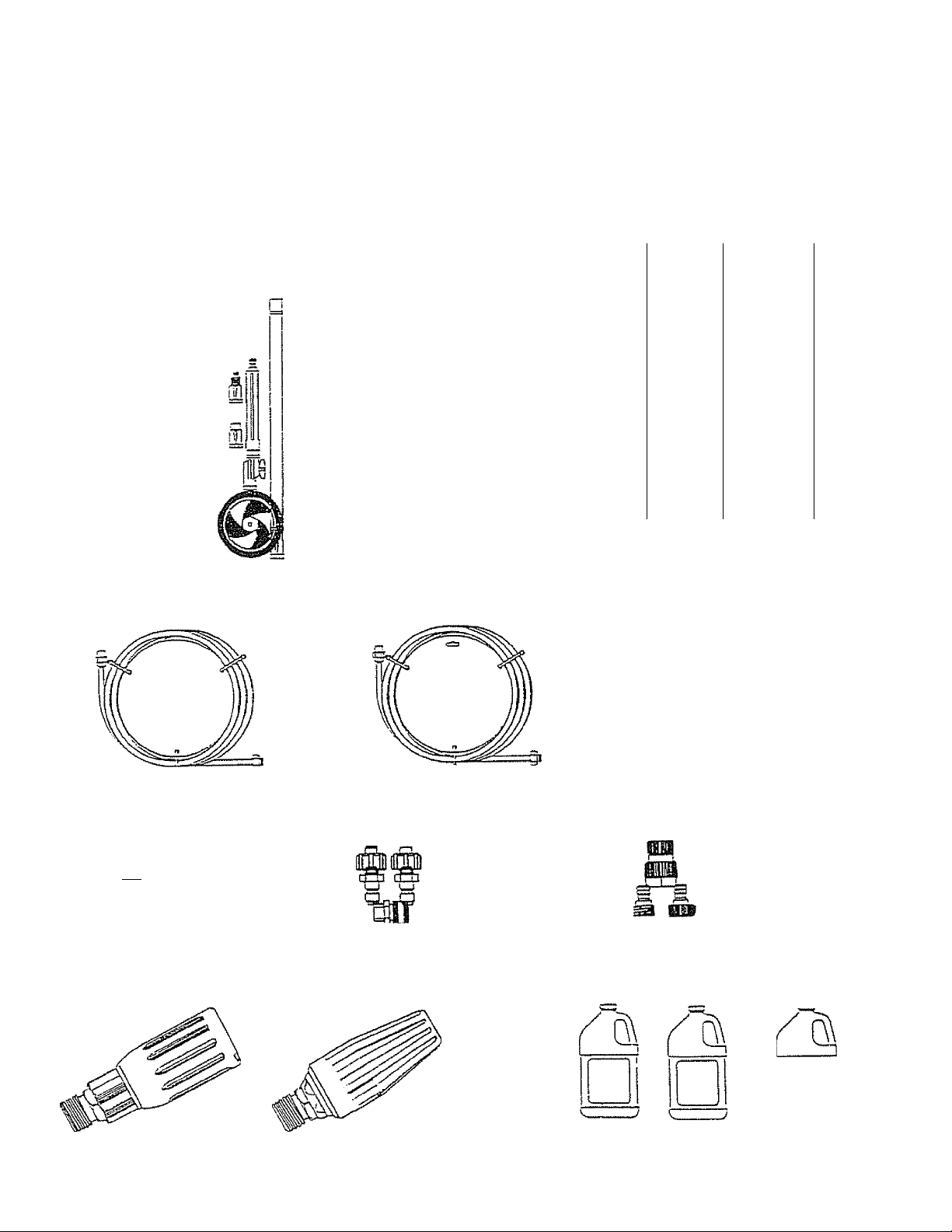
ACCESSORIES AND ATTACHMENTS
These accessories and attachments were available when the high pressure washer was purchased. They are also
available at most Sears retail outlets and service centers. Most Sears stores can order these items for you when you
provide the model number of your high pressure washer. Some of these accessories may not apply to your pressure
washer.
|i
n
Sta
1
iTil
FLOOR/SIDING
BRUSH KIT (75190)
1/4” I.D. 25 ft. EXTENSION
HOSE (75192)
rftt
HIGH PRESSURE
HOSE QUICK CON
NECT KIT (75198)
ROTATING BRUSH
KIT (75199)
g
ACCESSORY
QUICK CONNECT
(76188)
y
UTILITY BRUSH Krr
(75189)
3/8* i.D. 50 ft. EXTENSION
HOSE (75913)
ACCESSORY
QUICK CONNECT
STARTER KIT
(75197)
ap
18* STAINLESS
STEEL EXTENSION
(75194)
HIGH PRESSURE
HOSE TO HOSE
COUPUNG
(75191)
ELECTRIC TURBO
NOZZLE
GCZBjaBD
n
CHEMICAL INJECTION
FOAMER (74180)
GARDEN HOSE
QUICK CONNECT
WITH 2 ADAPTORS
(75187) •
ANGLE EXTENSION'
KIT (75196)
PRESSURE
GAUGE (75181)
TURBO HEAD
1800 PS! (max.)
TURBO NOZZLE
2200 and 2500 PSi (75186)
MULTI-PUR-
POSE/HOUSE
WASH (75100)
DECK WASH
(75101)
VEHICLE/BOAT
WASH (75102)
DEGREASER
(75103)
Page 6
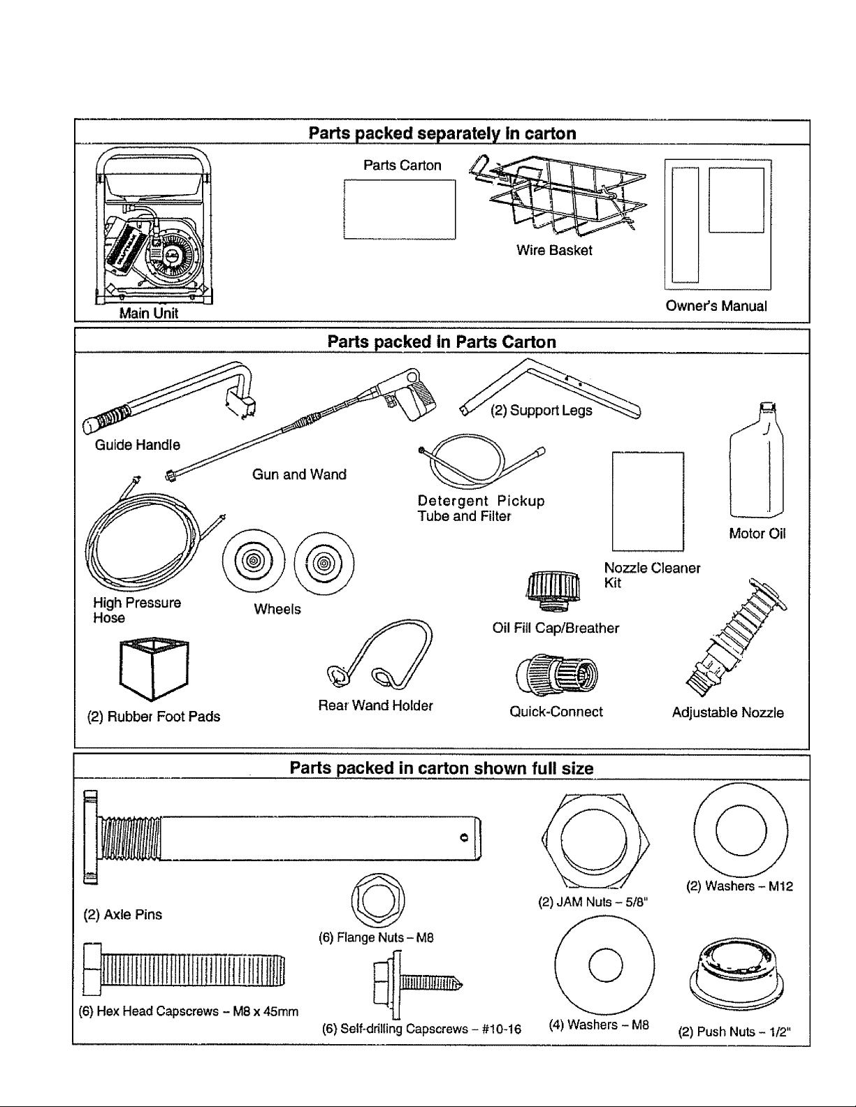
CONTENTS OF HARDWARE PACK
Page 7
ASSEMBLY
Read these instructions and Operator's Manual in its en
tirety before you attempt to assemble or operate your new
high pressure washer. Your high pressure washer has, for
the most part, been assembied at the factory, except those
parts left unassembled. Before you can operate your new
high pressure washer, you must assemble the wheel kit and
properly connect the high pressure hose.
IF YOU HAVE ANY PROBLEMS WITH THE ASSEMBLY
OF YOUR PRESSURE WASHER, PLEASE CALL THE
PRESSURE WASHER HELPLINE AT 1-800-222-3136.
TOOLS REQUIRED FOR ASSEMBLY
Mallet
2 adjustable wrenches OR the following wrenches:
5/16“ {8mm) combination wrench
1/2" (13mm) combination wrench
11/16“ (18mm) combination wrench
7/8“ (22mm) combination wrench
15/16“ (24mm) combination wrench
TO REMOVE PRESSURE WASHER FROM CARTON
» Remove box for spray gun assembly and support legs
o Remove accessories box from carton.
8 Remove wire basket (wrapped in plastic)
8 Remove your high pressure washer.
Refer to Page 6, “Contents of Hardware Pack" for an
illustrated listing of all Items included with your pressure
washer. Become familiar with each piece before assem
bling pressure washer. Check all contents against iliustrations on Page 6, If any parts are missing or damaged, call
Pressure Washer Helpline, at 1-800-222-3136.
FIG. 1
HOW TO SET UP YOUR PRESSURE WASHER
TO INSTALL THE WHEEL KIT
Installing the wheel kit requires the tools listed above, the
guide handle and items included in the parts carton.
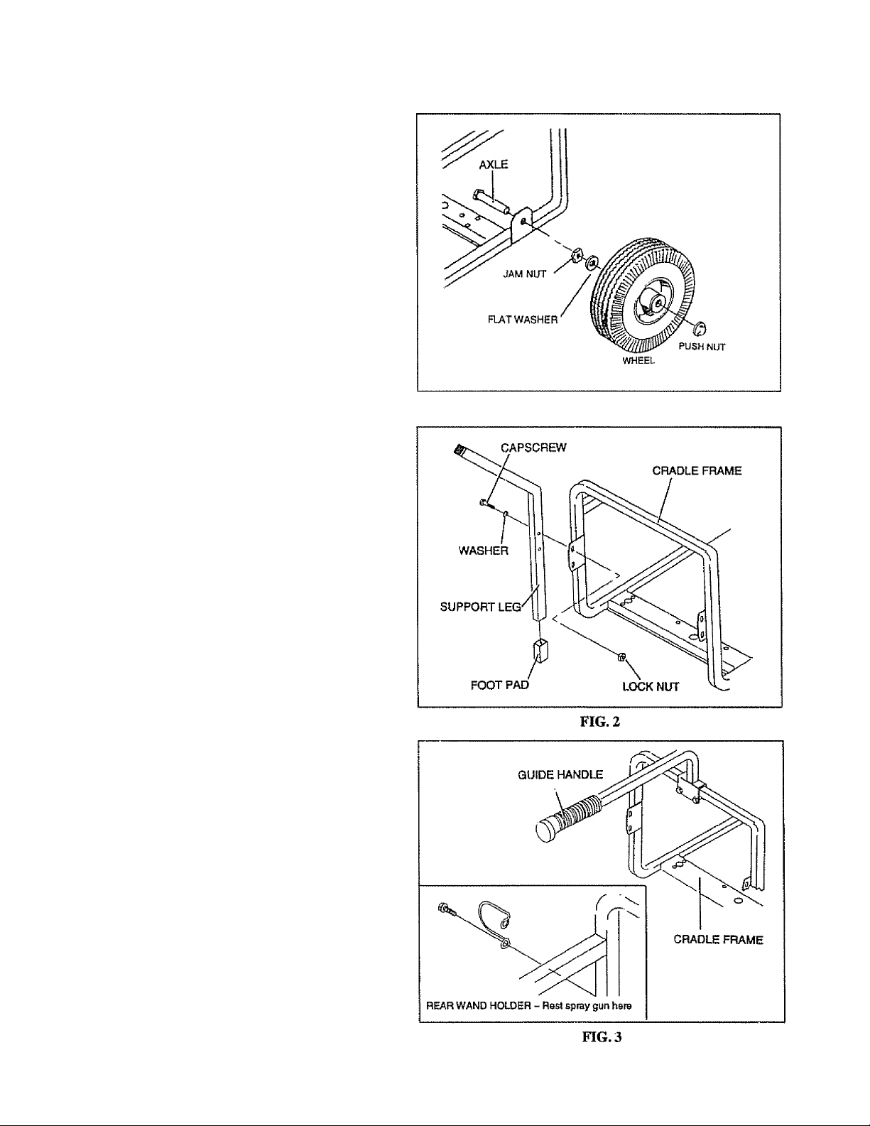
8 Prop up the engine end of the main unit. This will allow
you to slip each axle pin into the holes provided on the
side of the base (Fig. 1)
8 Fasten each axle to base with 5/8"-18 JAM nut then place
M12 fiat washer over axle. Tighten with 15/16" wrench,
8 Place wheels with valve side of wheel facing outboard
side onto the axles and retain each wheel to its axle by
tapping a push nut onto end of axle with a mallet.
8 Insert foot pad into bottom of each support leg (Fig. 2).
8 Using 13mm or 1/2-inch wrench, attach each support
leg to base as shown in Fig. 2 with two MB x 45mm hex
head capscrews, MB washers and M8 flange lock nuts.
8 Attach guide handle to cradle (Fig, 3) with two M8-1.25
X 45mm hex head capscrews and two flange nuts.
Attach rear wand holder using 5/16" (8mm) wrench with
#10-16 self-drilling screws to cradle as shown in Fig. 3.
Page 8
ASSEMBLY
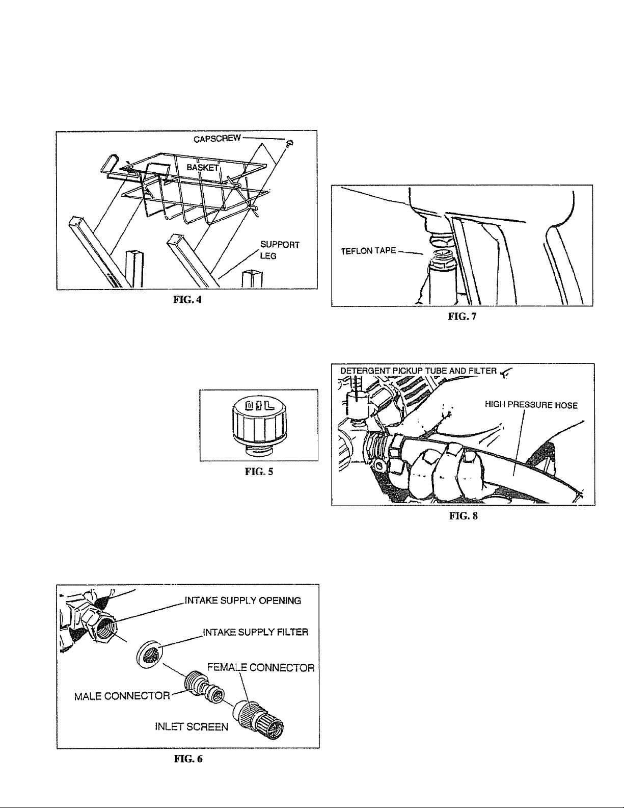
Attach wire basket to bent arms of support legs with
#10 self-drilling screws (Fig. 4) using 5/16“ (8mm)
wrench. The gun holder should be positioned to the
left. Be sure loop of support is pointing upward.
TO ASSEMBLE REMAINING COMPONENTS
IMPORTANT: YOU MUST ASSEMBLE WAND AND AT
TACH ALL HOSES BEFORE YOU START ENGINE.
STARTING ENGINE WITHOUT ALL HOSES CON
NECTED AND WATER SUPPLIED WILL DAMAGE
PUMP.
Unravel high pressure hose, remove protective cap
from end of hose and cfieck other end of hose to see
ttiat threads are properly covered with teflon tape, if
tape is not properly applied, reapply it so frireads are
fully covered. The tape seals the connection from hose
to gun and wand assembly.
Attach fitting with teflon tape to gun and wand assembly
(Fig. 7). You may want to spin gun. Tighten with 7/8“
wrenches or adjustable wrenches.
o Attach the other end of the high pressure hose to high
pressure fitting on pump (Fig. 8). Tighten with adjust
able wrench.
Remove cap from top of
pump and insert oil fill
cap included in parts bag
(Fig. 5).
included with ttiis unit is a Quick-Connect fitting you
attach to Water Inlet on pump. The quick-connect
includes two parts — a Male Connector factory-in
stalled on water inlet and a Female Connector (Fig. 6).
Remove male connector to inspect Intake Supply
Screen in water inlet for cleanliness and inspect Inlet
Screen on female connector, install male connector to
water inlet and attach female connector to garden
hose.
o Unravel Detergent Pickup Tube and place filter in
basket.
IMPORTANT: KEEP DETERGENT PICKUP TUBE AWAY
FROM HOT MUFFLER,
<* Attach Detergent Pickup Tube as shown in Fig. 8.
o To attach the adjustable nozzle, refer to Operation
section, Fig. 11.
CHECKLIST
o Check that fasteners you used to install wheels and
handle are tight. Vibration during operation may
loosen fasteners that are not tight enough.
o Check for proper hose connections (high pressure and
water supply) and for tight connections and that tiiere
are no kinks, cuts, or damage to the high pressure
hose.
o Provide proper water supply (not to exceed 140°F).
o Be sure to read "Safety Rules” and "Operation” sec
tions before using the pressure washer.
Page 9
OPERÄTfOlSl
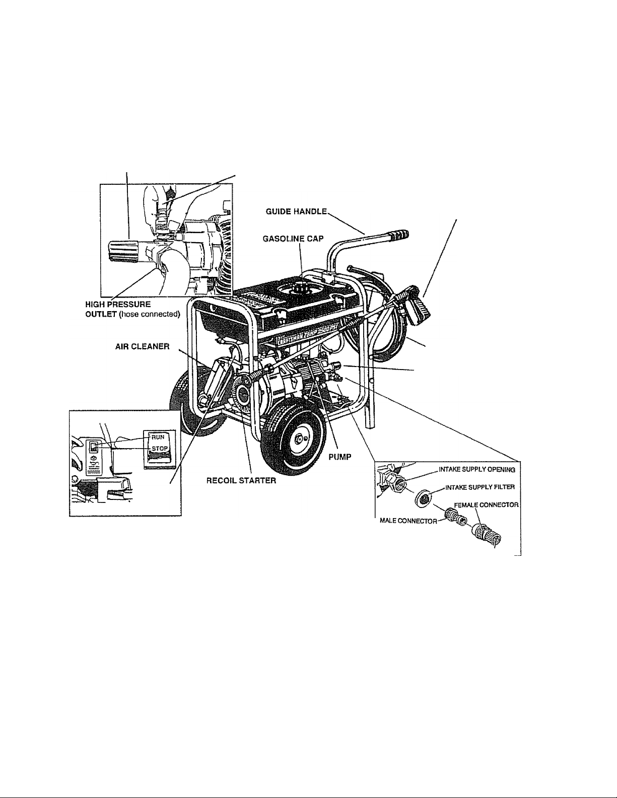
KNOW YOUR HIGH PRESSURE WASHER
READ THIS OWNER’S MANUAL AND SAFETY RULES BEFORE OPERATING YOUR HIGH PRESSURE WASHER.
Compare the illustrations with your high pressure washer to familiarize yourself with the locations of various controls and
adjustments. Save this manual for future reference.
PRESSURE
REGULATOR
DETERGENT PICK TUBE
AND FILTER
GUN AND WAND
ASSEMBLY
■ HIGH PRESSURE HOSE
ENGINE RUN/STOP SWITCH
FIG. 9
PUMP —Develops high pressure.
PRESSURE REGULATOR — Allows you to adjust the
pressure of the outlet stream.
ENGINE ON-OFF CONTROL — Sets engine in starting
mode for recoil starter; turns OFF mnning engine.
RECOIL STARTER — Used for starting the engine manu
ally.
AIR CLEANER - Dry type filter element limits the amount
of dirt and dust that gets in the engine.
GUN AND WAND ASSEMBLY—Controls the application
of water onto cleaning surface with trigger device. Includes
safety latch.
-PRESSURE REGULATOR
INLET SCREEN
QUICK-CONNECT
HIGH PRESSURE HOSE — Connect one end to water
pump and other to spray wand.
INTAKE SUPPLY FILTER — Filters inlet water supply.
DETERGENT PICKUP TUBE AND FILTER—Mixes water
and detergent in outlet water flow.
HIGH PRESSURE OUTLET — Connection for high pres
sure hose.
QUICK-CONNECT — Easy connection for intake water
supply.
Page 10

OPERATiON
HOW TO USE YOUR WASHER
IF YOU HAVE ANY PROBLEMS OPERATING YOUR
PRESSURE WASHER, PLEASE CALL THE PRESSURE
WASHER HELPLINE AT 1-800-222-3136.
STOPPING YOUR PRESSURE WASHER
» First, move engine RUN/STOP switch to "OFF" position
(Fig. 10).
FIG. 10
e Simply shutting OFF engine will not release pres
sure In the system. Pull the trigger on the spray wand
assembly to relieve the pressure in the hose,
NOTE: A small amount of water will squirt out when you
release the pressure.
SPRAY NOZZLES
Your high pressure washer comes equipped with an adjust
able nozzle (Fig. 11). You can order a turbo nozzle (Fig,
12). Attach either nozzle as shown in Fig. 11 and HAND
TIGHTEN the plastic knob.
HOWTO USE ADJUSTABLE NOZZLE
WARNING; NEVER ADJUST SPRAY PATTERN
A
WHEN SPRAYING. NEVER PUT HANDS IN FRONT
OF SPRAY NOZZLE TO ADJUST SPRAY PAT
TERN.
With the adjustable nozzle you can adjust the spray pattern
to be either high pressure or low pressure. You can also
adjust the spray so it is concentrated in a stream pattern or
expanded into a fan pattern. Use this nozzle to apply
detergent.
« Push the nozzle attachment forward when you wish to
adjust the spray to low pressure mode (Fig. 13). Push
the nozzle backwatxi to achieve high pressure.
o Twisting the nozzle adjusts the spray pattern from a
narrow stream to an expanded stream.
You can also adjust the pressure by turning the pressure
control knob (Fig. 14) to the desired pressure setting.
Turning this knob ail the way clockwise produces the high
est pressure. Do not unscrew the pressure control valve
more than 3 turns. It will come off.
FIG. 14
NOZZLE IN HIGH
PRESSURE MODE
PUSH NOZZLE FORWARD FOR
LOW PRESSURE MODE AND DE
TERGENT APPLICATION
TWIST NOZZLE TO
EXPAND SPRAY
FIG. 13
10
TWIST NOZZLE TO NARROW
SPRAY STEAM
Page 11

OPERATION
APPLYING DETERGENT WITH ADJUSTABLE
NOZZLE
IMPORTANT: USE SOAPS DESIGNED SPECIFICALLY
FOR PRESSURE WASHERS. HOUSEHOLD DETER
GENTS COULD DAMAGE THE PUMP.
IMPORTANT: YOU MUST ATTACH ALL HOSES BE
FORE YOU START THE ENGINE. STARTING THE EN
GINE WITHOUT ALL THE HOSES CONNECTED WILL
DAMAGE THE PUMP.
Pressure washers are useful cleaning tools designed to
clean almost any surface in two easy steps.
o The first step involves applying an appropriate deter-
gent/solvent solution to penetrate and loosen grime.
The detergent is applied at low pressure to avoid
splashing, overspraying and waste. Leave the solution
on surface for 3 to 5 minutes to allow solution to work,
o The second step involves cleaning the surface you
have prepared with the pressure washer and then
rinsing it clean.
To apply detergent follow these steps:
o Prepare your detergent solution as required by your
job.
o Place small filter of the clear, detergent siphoning tube
into the detergent container (Fig. 15),
o To stop flow of detergent, turn knob clockwise or re
move filter from detergent or set nozzle to high pres
sure position,
NOTE: Detergents are most effective when applied to a dry
surface.
PRESSURE WASHING/RINSING
WARNING: BE EXTREMELY CAREFUL IF YOU
A
MUST USE PRESSURE WASHER FROM LADDER,
SCAFFOLDING OR ANY OTHER RELATIVELY UN
STABLE LOCATION. PRESSURE IN A RUNNING
WASHER BUILDS IN THE WAND AS YOU CLIMB.
WHEN YOU PRESS THE TTHGGER, THE RECOIL
FROM THE INITIAL SPRAY COULD FORCE YOU
TO FALL, OR IF YOU ARE TOO CLOSE TO THE
CLEANING SURFACE, HIGH PRESSURE COULD
FORCE YOU OFF CLIMBING APPARATUS.
Set nozzle to low pressure mode. Detergent is not
siphoned in the high pressure mode (Fig. 13).
Start washer and apply detergent to a dry surface,
starting from the bottom and working up. You can
adjust the concentration of detergent by turning the
knob on the detergent injector (Fig. 16).
o Hook up water supply (Fig, 17).
o Adjust nozzle to select high pressure mode.
NOTE: Detergent will not flow when in the high pressure
mode.
o Start washer and work from the top of the surface to
the bottom,
NOTE: The high pressure mode is most effective when the
tip of the wand is held between 6 inches to two feet from
the surface being cleaned.
HOW TO USE OPTIONAL TURBO NOZZLE
8 The optional rotating turbo nozzle, in essence, expands
the area of the high pressure stream,
8 You cannot adjust the spray pattern with this nozzle.
8 You cannot apply detergent with this nozzle.
BEFORE STARTING THE ENGINE
To operate the engine you will need the following:
ENGINE OIL
IMPORTANT: ANY ATTEMPT TO CRANK OR START
THE ENGINE BEFORE IT HAS BEEN PROPERLY SERV
ICED WITH THE RECOMMENDED OIL RESULTS IN AN
ENGINE FAILURE,
A 20 oz. bottle of SAE 30 weight oil is included in the parts
carton,
11
Page 12

OPERATION
NOTE; When adding oii to the engine crankcase in the
future, use only higti quality detergent oil rated with API
service classification SC, SD, SE, SF, SG rated SAE 30
weight. Use no special additives. Select the oil’s viscosity
grade according to your expected operating temperature.
colder
5W30
Although multi-viscosity oils (5W30,10W30, etc.) improve
starting in cold weather, these multi-viscosity oils will result
in increased oil consumption when used above 32°F.
Check your engine oil level more frequently to avoid possi
ble damage from running low on oil. Oil sump capacity is
21 ounces,
ADD ENGINE OIL;
CAUTION: ANY ATTEMPT TO CRANK OR START
THE ENGINE BEFORE IT HAS BEEN PROPERLY
SERVICED WITH THE RECOMMENDED OIL RE
SULTS IN AN ENGINE FAILURE.
Place pressure washer on a level surface and remove
one of yellow Oil Fill Caps (Fig. 18), insert clean funnel
in opening, and add engine oil from the enclosed bottle
until level is at point of overflowing. Check engine oii
level before starting each time thereafter. If oil level is
below point of overflowing, fill to proper level. Crank
case oil capacity is about 620ml or 21 fluid ounces.
32°F warmer
SAE30
TO SEPARATION AND FORMATION OF ACIDS DURING
STORAGE. ACIDIC GAS CAN DAMAGE THE FUEL SYS
TEM OF AN ENGINE WHILE IN STORAGE. TO AVOID
ENGINE PROBLEMS, THE FUEL SYSTEM SHOULD BE
EMPTIED BEFORE STORAGE OF 30 DAYS OR
LONGER. SEE “STORAGE” ON PAGE 17. NEVER USE
ENGINE OR CARBURETOR CLEANER PRODUCTS IN
THE FUEL TANK OR PERMANENT DAMAGE MAY OC
CUR.
o Clean area around fuel fill cap, remove cap,
o Add “UNLEADED" regular gasoline, slowly, to fuel
tank,
«• Install fuel cap and wipe up any spilled gasoline.
TO TURN ON WASHER
0 Attach one end of a garden hose to a cold water source.
Water supply should not exceed 140°F (55°C).
o Check that high pressure hose is attached to pump
outlet and that water supply is attached to pump inlet.
o Turn ON water,
a Press trigger on gun and wand assembly to force air
from high pressure hose,
a Start engine according to ‘TO START THE ENGINE."
TO START THE ENGINE
IMPORTANT; DO NOT RUN PUMP WITHOUT THE
WATER SUPPLY CONNECTED AND TURNED ON
a Start, store and fuel the unit in a level position,
a Open fuel shut-off valve,
a Press trigger on pressure washer wand to relieve high
pressure and/or purge the inlet hose of air.
a Adjust safety latch on spray gun to the ON position.
This disables the trigger so you cannot inadvertently
actuate a high pressure spray (Fig, 19).
ADD GASOLINE:
CAUTION: DO NOT OVERFILL THE FUEL TANK.
ALWAYS ALLOW ROOM FOR FUEL EXPANSION.
WARNING: NEVER FILL FUEL TANK INDOORS.
NEVER FILL RJEL TANK WHEN ENGINE IS RUN
NING OR HOT. DO NOT LIGHT A CIGARETTE OR
SMOKE WHEN FILLING FUEL TANK.
a Use regular UNLEADED gasoline with the pressure
washer engine. Regular leaded gasoline may also be
used if UNLEADED is not available. Fuel tank capacity
is 4 U.S. gallons.
IMPORTANT: IT IS IMPORTANT TO PREVENT GUM
DEPOSITS FROM FORMING IN ESSENTIAL FUEL SYS
TEM PARTS SUCH AS THE CARBURETOR, FUEL FIL
TER, FUEL HOSE OR TANK DURING STORAGE. ALSO,
EXPERIENCE INDICATES THAT ALCOHOL-BLENDED
FUELS (CALLED GASOHOL OR USING ETHANOL OR
METHANOL) CAN ATTRACTMOISTURE WHICH LEADS
Locate the Run/Stop switch (Fig, 20 on Page 13) next
to the engine cylinder head and set it to RUN,
Close the choke to FULL position (Fig. 21 on Page 13)
by sliding it to far position in direction indicated by arrow
on air cleaner housing.
Turn pressure control knob counterclockwise, two
turns from maximum pressure.
12
Page 13

OPERATION
FIG. 20
o Grasp the starter grip and pull slowly until you fee!
resistance. Then pull rapidly one time.
® When engine starts, move choke lever to "RUN" posi
tion. If engine fails to start, move choke lever to "RUN"
position and puli starter rope (maximum 2 pulls).
® If engine fails to start, repeat the previous two steps.
o Once engine has started, place the Safety Latch on
spray gun to the OFF position.
o Press trigger on gun and wand assembly. Water should
spray out the nozzle.
o Adjust nozzle for correct pressure, spray angle. You
can also turn the pressure control knob to the desired
pressure setting.
o Your pressure washer is ready to use.
IMPORTANT: AN INTERNAL THERMAL RELIEF VALVE
HAS A MAXIMUM TEMPERATURE SETTING OF 140°F
(60°C). IF YOU RUN THE PUMP FOR 5 MINUTES WITH
OUT PRESSING THE TRIGGER ON THE SPRAY GUN,
1/2 TO 1 OUNCE OF WATER IS RELEASED THROUGH
THE VALVE TO COOL THE UNIT. THE SMALL AMOUNT
OF WATER WILL DRIP OUT THE BOTTOM OF PUMP.
LOW OIL PRESSURE SHUTDOWN SYSTEM
The engine is equipped with a low oil pressure sensor that
shuts down the engine automatically when the oil pressure
drops below 6 psi. If the engine shuts down by itself and
the fuel tank has enough gasoline, check engine oil level.
INITIAL STARTUP
A delay built in the shutdown system allows oil pressure to
build during starting. The delay allows the engine to run for
about 10 seconds before sensing oil pressure.
SENSING LOW OIL PRESSURE
If the system senses low oil pressure during operation, the
engine shuts down. As the system shuts down, Oie low oil
light comes ON. However, once the engine has stopped
rotating, this light will go OFF, See Fig. 22 for schematic.
RESTARTING
If you try to restart the engine within 5 seconds after it shuts
down, the engine may NOT start, The system needs 5 to
10 seconds to reset.
If you do restart the engine after such a shutdown and
have not corrected the low oil pressure, the engine
runs for about 10 seconds as described above and then
stops.
SIPHONING
We recommend that you DO NOT siphon your water supply
from sources other than from connecting to household
water supply.
TIPS
Initially clean an area and then check the surface for
damage. If no damage is found, you can assume it is
okay to continue cleaning. Detergents work best when
applied to dry surface.
For most effective cleaning, keep spray nozzle be
tween 8 to 24 inches of cleaning surface.
Allow the detergent to soak in between 3-5 minutes
before washing and rinsing.
For cleaning, start at lower portion of area to be washed
and work upward, using long, even overlapping
strokes.
For rinsing, push nozzle sleeve to high pressure and
wait for detergent to clear. Start at top of area to be
rinsed, working down with same action as for cleaning.
Never use garden hose inlet to siphon detergent or
wax.
If you get the spray nozzle too close, especially using
high pressure mode, you may damage the cleaning
surface.
If you have the spray nozzle too far away, the cleaning
will not be as effective.
Do not get closer than 6 inches when cleaning automo
bile tires.
13
Page 14

CUSTOMER RESPONSIBILITIES
MAINTENANCE SCHEDULE
FILL IN DATES AS YOU COMPLETE
REGULAR SERVICE
MAINTENANCE TASK
PRESSURE WASHER
Check/clean inlet filter and screen
Check high pressure hose.
Check detergent hose.
Check gun and wand for leaks.
Check pump oil ❖ X
Purge pump of air and contaniments
ENGINE
Check oil level
Change engine oil. « X*
Rétorqué head bolts.
Service air cleaner.
Clean/replace spark plug.
Clean spar k arrestor screen.
Prepare for storage,.
HOURLY OPERATING INTERVAL
Every 25
Before
Each Use
XV
X
X
X
X
X
Prepare unit for storage if it is to remain idle
longer than 30 days
Hours or
Yearly
X**
Every 50
Hours or
Yearly
SERVICE DATES
Every 100
Hours or
Yearly
X
X
X
V Clean if clogged. Replace if perforated or torn ♦ ChangeoHafterfirstShours, then after every 50 hours.
* Chnnge sooiicr when qpemliiig under heavy load or high ambicnl temperature ** Clean more often under dusty conditions or wt)cn jarbome debris is present
GENERAL RECOMMENDATIONS
The warranty of the high pressure washer does not cover
items that have been subjected to operator abuse or negiigence. To receive full value from the warranty, operator
must maintain high pressure washer as instructed in this
manual
Some adjustments will need to be made periodicaliy to
properly maintain your high pressure washer.
All adjustments in the Service and Adjustments section of
this manual should be made at least once each season,
o Once a year you should replace the spark plug and
clean or replace the air filter and check the gun and
wand assembly for wear. A new spark plug and clean
air filter assure proper fuel-air mixture and help your
engine run better and last longer.
BEFORE EACH USE
o Check engine oil level.
o Check water inlet filter and quick-connect screen for
damage.
e Check high pressure hose for leaks,
o Check detergent inlet hose and filter for damage.
o Check gun and wand assembly for leaks,
o Purge pump of air and contaniments.
PRESSURE WASHER MAINTENANCE
Check and Clean Inlet Supply Filter and inlet Screen:
Remove quick-connect and examine inlet screen on the
female connector and filter on pump inlet fitting. Clean if
either is clogged or replace if either is torn.
Check High Pressure Hose: High pressure hose can
develop leaks from wear, kinking, abuse. Inspect hose
each time before using it. Check for cuts, leaks, abrasions
or bulging of cover, or damage or movement of couplings.
If any of these conditions exist, replace hose immediately.
DANGER: WATER SPRAYING FROM A LEAK £ CA
PABLE OF INJECTING MATERIAL INTO SKIN. NEVER
REPAIR HIGH PRESSURE HOSE. REPLACE WITH
HOSETHATMEETS MINIMUM PRESSURE RATING OF
YOUR PRESSURE WASHER.
Check Detergent Hose: Examine the filter on the deter
gent hose and clean if clogged. Hose should fit tightly on
barbed fitting. Examine hose for leaks or tears. Replace
the filter or hose if either is damaged.
Check Gun and Wand: Examine hose connection to gun
and make sure it is secure. Test trigger by pressing it and
making sure it springs back into piace when you release it.
Put safety latch in ON position and test trigger. You should
not be able to press trigger.
Check Pump Oil: Refer to PUMP MAINTENANCE for
information.
14
Page 15

CUSTOMER RESPONSIBILITIES
Purge Pump of Air and Contanlments;
To remove the air from the pump, follow these steps:
o Set up the pressure washer as described in the AS
SEMBLY section and connect the water supply.
<9 Remove the nozzle attachment from the gun.
o Pull the trigger on the gun and hold.
To remove the contanlments from the pump, foliow these
steps:
» Set up the pressure washer as described in the AS
SEMBLY section, connect the water supply and start
the engine according to instructions in the OPERA
TION section.
e Remove the nozzle attachment from the gun.
o Pull the trigger on the gun and hold.
o When thewatersupplyissteadyandconstant.you may
refasten the nozzle attachment and start the pump.
PUMP MAINTENANCE
WARNING: DO NOT ATTEMPT TO DISASSEMBLE
A
THE PUMP. WITHOUT THE PROPER TECHNIQUE,
ATTEMPTING TO DISASSEMBLE PUMP MAY
CAUSE PERSONAL INJURY. FOR SERVICE, CON
SULT A SEARS AUTHORIZED SERVICE CENTER
OR CONTACT YOUR PLACE OF PURCHASE.
CHANGING ENGINE OIL
o Change oil after first 8 hours of operation. Change oil
every 50 hours thereafter, if you are using your pres
sure washer under extremely dirty or dusty conditions,
or in extremely hot weather, change oil more often.
6 Change oil white engine is still warm from running, as
follows:
CAUTION: DISCONNECT SPARK PLUG WIRE
A
FROM SPARK PLUG AND KEEP IT AWAY FROM
SPARK PLUG.
Clean area around oil drain plug, remove plug and drain
oil completely into a suitable container (Fig. 23).
Pump Oil: Change pump oil after first 50 hours of opera
tion. Change pump oil every time you change the engine
oil. To change pump oil, follows these steps:
<* Place a proper container beneath the pump (Fig. 22).
OIL, LEVEL GAUGE
OIL DRAIN PLUG
BTG. 22
» Remove the Oil Drain Plug of pump and drain oil into
the container.
» When oil has drained completely, reinstall oil drain
plug.
o Remove pump's oil fill plug, insert funnel and add
recommended SAE 80W-90 oil until level reaches full
mark on gauge located on side of the pump. Capacity
is 5 ounces (150 grams).
» Reinstall the pump’s oii fill plug.
plug.
a Remove yellow oil fill plug and insert a clean fill funnel
into plug opening. Fill engine crankcase with recom
mended oii until oil level is at point of overflowing. Do
not overfili above the point or overflowing. About 21
ounces {620ml) is required. POUR SLOWLY.
o When engine crankcase is filled to proper level. Install
and tighten oil fili plug.
RETORQUE HEAD BOLTS
After 50 hours of operation, retorque the head bolts for this
GN-Series engine to 4.0 kg/m (29 foot-pounds).
ENGINE MAINTENANCE
CHECKING OIL LEVEL
Oil level should be checked prior to each use or at least
every 5 hours of operation. Keep oil level maintained.
Fig 24.
15
Page 16

CUSTOMER RESPONSÎBILITES
SERVICE AIR CLEANER
CAUTION: NEVER RUN THIS UNIT WITHOUT THE
A
COMPLETE AIR CLEANER SYSTEM INSTALLED
ON THE ENGINE. THIS COULD RESULT IN PRE*
MATURE WEAR TO THE ENGINE.
Your engine will not run properly and may be damaged if
you run it using a dirty air cleaner.
Clean or replace the air cleaner paper filter (Fig. 25) once
every 25 hours of operation or once a year, whichever
comes first. Clean or replace more often if operating under
dusty or dirty conditions. Clean foam pre-filter every 25
hours of operation or sooner under dusty conditions.
FOAM
PRE-FiLTER
COVER
CLEAN/REPLACE SPARK PLUG
Change tfie spark plug every 100 hours of operation or
once each year, whichever comes first. This will help your
engine to start easier and run better. Replace with Cham
pion RC12YC or equivalent type spark plug. Set spark plug
gap 0-030 inch (0,76mm).
CLEAN SPARK ARRESTOR SCREEN
The engine exhaust muffler has a spark arrestor screen,
inspect and clean the screen every 100 hours of operation
or once each year, whichever comes first.
WARNING: LET THE MUFFLER COOL BEFORE
A
WORKING ON IT. CONTACT WITH A HOT MUF
FLER OR ENGINE CAN CAUSE SEVERE BURNS.
FIG. 25
To clean or replace foam pre-filler:
« Remove air cleaner cover, tfien foam pre-filter.
0 Wash pre-filter in soap water. Squeeze pre-cleaner dry
in clean cloth (DO NOT TWIST).
« Clean air cleaner cover before installing it.
To clean or replace paper air filter;
» Remove air cleaner cover; then remove foam pre-filter
(service if necessary) and remove paper filter.
0 Clean air filter by tapping it gently on a solid surface. If
the filter is too dirty, replace it witfi a new one. Dispose
of the old filter properly.
0 Clean air cleaner coverthen Insert pre-filter into cover.
Next insert new paper filter into cover to hold pre-filter
in place and assemble ail of them to the base of the air
cleaner.
FIG. 26
NOTE: If you use your pressure washer on any forest-cov
ered, brush-covered or grass-covered unimproved land, it
must have a spark arrestor. The spark arrestor must be
maintained in good condition by the owner/operator.
Clean and inspect the spark arrestor as follows:
a To remove the muffler guard from the muffler, remove
the three screws that connect tfie guard to the muffler
bracket (Fig. 26)
a Remove four screws that attach the spark arrestor
screen.
0 Inspect screen and replace if torn, perforated or other
wise damaged. DO NOT USE a defective screen. If
screen is not damaged, clean it with commercial sol
vent.
o Reattach the screen and the muffler guard.
16
Page 17

SERVICE AND ADJUSTMENTS
ENGINE SPEED
CAUTION: ENGINE SPEED WAS PROPERLY AD
A
JUSTED AT THE FACTORY AND SHOULD RE
QUIRE NO ADDITIONAL ADJUSTMENT. DO NOT
ATTEMPT TO CHANGE ENGINE SPEED. IF YOU
BELIEVE THE ENGINE IS RUNNING TOO FAST OR
TOO SLOW, TAKE YOUR PRESSURE WASHER TO
SEARS AUTHORIZED SERVICE CENTER FOR RE
PAIR AND ADJUSTMENT. CHANGING ENGINE
GOVERNED SPEED WILL VOID ENGINE WAR
RANTY.
Your pressure washer runs at a constant speed. This
constant operating speed is maintained by a mechanical,
flyweight type, fixed speed governor. DO NOT try to adjust
the governed speed setting for the following reasons:
o High engine speeds are dangerous and increase the
risk of personal Injury or damage to equipment.
Low engine speeds impose a heavy load on the engine
when sufficient engine power is not available and may
shorten engine life.
ADJUSTING VALVE CLEARANCE
After the first 50 hours of operation, you should adjust the
valve clearance in the engine.
When adjusting valve clearance, engine should be at room
temperature and piston should be at Top Dead Center
(TDC) of compression stroke (both valves closed). Correct
clearance is 0.05-0.1 mm. Adjust valve clearance as fol
lows:
o Loosen the rocker arm jam nut. Use an alien wrench
to turn the pivot ball stud while checking clearance
between the rockerarm and the vaive stem with a feeler
gauge (Fig. 27).
o When valve clearance is correct, hold pivot ball stud
with alien wrench and tighten rocker arm jam nut with
crows foot. Tighten jam nut to 65-85 inch-pounds
torque. After tightening jam nut, recheck valve clear
ance to make sure it did not change (Fig. 28).
NOZZLE MAINTENANCE
If the nozzle becomes restricted or clogged with foreign
materials, such as dirt, excessive pump pressure may
develop. A partially clogged nozzle can cause a pulsing
sensation during use. This generally is not a pump related
problem, but rather a clogged or partially restricted nozzle.
If the nozzle becomes clogged or partially restricted, imme
diately clean the nozzle with the kit included with your
pressure washer by following tiiese instructions:
o Shut off the engine and turn off the water supply.
0 Separate the wand from the gun.
o Remove nozzle from the end of the wand using a 2mm
or 5/64 alien wrench (like the one included in the kit).
o Use the wire included in the kit (Fig. 29) or a small paper
clip to free the foreign materials clogging or restricting
the nozzle.
17
Page 18

SERVICE AND ADJUSTMENTS
Remove additional debris by back flushing water sup
ply through wand (Fig. 30). Back flush between 30 to
60 seconds. Turn wand to stream spray and move
nozzle from low to high while flushing.
Reinstall nozzle into the wand. DO NOT overtighten.
Reconnect the wand to the gun
Reconnect the water supply, turn on the water, and
start the engine.
STORAGE
AFTER EACH USE
Water should not remain in the unit for long periods of time.
Sediments of minerals can deposit on pump parts and
“freeze” pump action. Follow these procedures after every
use:
o Flush detergent hose by placing the injector filter into
a pail of clear water while running Pressure Washer
with nozzle in low pressure mode. Flush until you can
see clear water running ttirough the tube.
o Shut off the engine and let it cool, then remove all
hoses.
CAUTION: BE SURE THE THROTTLE LEVER IS IN
A
“STOP” POSITION BEFORE YOU CONTINUE. IF
YOU START THE ENGINE WfTHOUTTHE PROPER
WATER SUPPLY CONNECTED, YOU CAN DAM
AGE THE PUMP.
® Empty the pump of all pumped liquids by pulling recoil
handle about 6 times. This should remove most of the
liquid in the pump.
o Coil the high pressure hose and inspect it for damage.
Cuts in ttie hose or fraying of it could result in leaks and
loss of pressure. Should any damage be found, replace
the hose. DO NOT attempt to repair a damaged hose
and use it. Replace the hose with the genuine Crafts
man part.
® Drain water from hose and properly hang it on the wire
support provided on the guide handle.
NOTE: To protect the unit from freezing temperatures, you
can draw windshield washer fluid into the pump by pouring
the washer fluid into a 3-foot section of garden hose con
nected to the inlet adaptor and pulling the recoil handle
twice,
® Store in a clean, dry area.
LONG TERM STORAGE
WARNING: NEVER STORE ENGINE WITH FUEL IN
A
TANK INDOORS OR IN ENCLOSED, POORLY VEN
TILATED AREAS WHERE FUMES MAY REACH AN
OPEN FLAME, SPARK OR PILOT LIGHT AS ON A
FURNACE, WATER HEATER, CLOTHES DRYER
OR OTHER GAS APPLIANCE.
If you do not plan to use the Pressure Washer for more than
30 days, you must prepare the engine for long term storage.
Test the pressure washer by operating with nozzle in
the high and in the low position.
NOTE: As always, prepare the pressure washer pump as
you would after each use.
It is important to prevent gum deposits from forming in
essential fuel system parts such as the carburetor, fuel
filter, fuel hose or tank during storage. Also, experience
indicates that alcohol-blended fuels (called “gasohol" or
using ethanol or methanol) can attract moisture which leads
to separation and formation of acids during storage. Acidic
gas can damage the fuel system of an engine while in
storage.
To avoid engine problems, the fuel system should be
emptied before storage of 30 days or longer. Follow these
instructions:
Protect Fuel System; Engines stored over 30 days need
to be protected or drained of fuel to prevent gum deposits
from forming in fuel system or on essential carburetor parts.
® For engine protection use a fuel stabilizer. Mix stabilizer
with fuel in fuel tank and run engine for short time to
circulate stabilizer through carburetor.
• If you did use “gasohol", run engine until engine stops
from lack of fuel. Make sure you have water supply to
pump inlet connected and turned ON.
Change Oil: While engine is still warm, drain oil from
crankcase. Refill with recommended grade.
Oil Cylinder Bore: Remove spark plug and pour about 1/2
ounce (15ml) of engine oil into the cylinder. Cover spark
plug hole with rag. Crank slowly to distribute oil.
CAUTIONI AVOID SPRAY FROM SPARK PLUG
A
HOLE WHEN CRANKING ENGINE SLOWLY.
o Install spark plug. Do not connect spark plug wire.
OTHER
® Do not store gasoline from one season to another.
® Replace your gasoline can if your can starts to rust.
Rust and/or dirt in your gasoline will cause problems.
e If possible, store your unit indoors and cover it to give
protection from dust and dirt. BE SURE TO EMPTY
THE FUEL TANK.
a Cover your unit with a suitable protective cover that
does not retain moisture.
IMPORTANT: NEVER COVER YOUR PRESSURE
WASHER WHILE ENGINE AND EXHAUST AREAS ARE
WARM.
18
Page 19

TROUBLESHOOTING
PROBLEM
Pump has foliowing problems:
failure to produce pressure, erratic
pressure, chattering, loss of pressure,
low water volume.
Detergent fails to mix with spray.
Engine ains good at no-load but "bogs
CAUSE
1, Nozzle in low pressure mode.
2. Low regulator pressure
3 Water inlet is blocked
4. Inadequate water supply
5,. Inlet hose is kinked or leaking
6 Clogged inlet hose strainer.
7. Detergent line is not submerged.
0, Water supply is over 140°F.
9. Outiet hose Is blocked or leaks.
10. Gun leaks.
11. Nozzle is obstructed.
12. Pump is faulty.
1. Detergent line is not submerged.
2 Chemical filter is clogged.
3. Nozzle is in high pressure mode.
4. Chemical adjuster is closed.
Engine speed is too slow.
CORRECTION
1. Pull nozzle backward for high
pressure mode.
2, Adjust regulator to desired setting.
3. Clear inlet
4. Provide adequate water flow.
5. Straighten inlet hose, patch leak,
6. Check and clean Inlet hose strainer,
7. Submerge detergent line
8. Provide cooler water supply.
9. Clear blocks in outlet hose.
10, Replace gun.
11. Clear nozzle.
12. Contact Sears Service Department.
1. Insert chemical line into detergent
2. Clean or replace fliter/detergent line.
3. Push nozzle fonvard for
low pressure mode.
4. Open chemical adjuster
Contact Sears Sen/ice Department.
Engine will not start; or starts
and runs rough
Engine shuts down during operation
Engine lacks power,.
1, Low oil level
2. Dirty air cleaner
3. Out of gasoline.
4. Stale gasoline.
5. Spark plug wire not connected
to spark plug
6. Bad spark plug.
7. Water in gasoline.
8. Oveirhoking.
9. Excessively rich fuel mixture.
10. Intake valve stuck open or closed.
11, Engine has lost compression.
1. Out of gasoline.
2 Low oil level.
Dirty air filter.
1 Fill crankcase to proper level.
2. Clean or replace air cleaner.
3. Fill fuel tank.
4. Drain gas tank; fill with fresh fuel.
5. Connect wire to spark plug.
6. Replace spark plug.
7. Drain gas tank; fill with fresh fuel,
8. Open choke fully and crank engine.
9. Contact Sears Service Department.
10 Contact Sears Service Department
11. Contact Sears Service Department.
1. Fill fuel tank,
2. Fill crankcase to proper level.
Replace air filter.
Engine “hunts” or falters.
Choke is opened too soon.
19
Move choke to halfway position
until engine runs smoothly.
Page 20

CRAFTSMAN 2500 PSI HIGH PRESSURE WASHER 580.751781
REPAIR PARTS
Drawing No.. 97023 20
Page 21

CRAFTSMAN 2500 PSI HIGH PRESSURE WASHER 580.751781
REPAIR PARTS
ITEM PART NO. DESCRIPTION ITEM
1
3 84021
4
5 90878 Fuel Cap (1 req.) 46 95194
6
7
8 96404
9
10
11
12
13 87840 Tank Heat Shield
14
15 84687 #21/4“ thick Insulation {1 req.)
16 95203 Cradle (1 req.)
17
18 70644 M8-1.25 X 20mm Screw (3 req.)
19 84346 M8-1.25 X 35mm Capscrew {2 req)
20 52858 M8-1.25 Flange Lock Nut {19 req )
21 95635 Pump Support Bracket (1 req )
22 38750 M6-1.0 X 30mm Capscrew (2 req)
24 87985 Rear Wand Holder (1 req.)
25 86292 #10-16 Capscrew (6 req.)
26 87836 Wire Basket (1 req)
27 93728A Axle Pin (2 req.)
28 94222Q 5/8“ JAM Nut (2 req.)
29 49808 M12 Flat Washer (2 req.)
30 88521 Wheel Assembly (2 req.)
31 75402 1/2“ Push Nut (2 req )
32
33 39287
34
35 46476 1" square Cap Plug {2 req.)
36 94135 Rubber Fool Pad (2 req.)
37
38 89712
39
40 92535 Muffler Support Bracket (1 req.)
41 40976 M8-1.25 X 20mm Capscrew (2 req.)
42
90508
88325 Fuel Tank (1 req ) 45
78298 Tank Valve {1 req.) 47 77584
78299 Plastic Tank Bushing (1 req.) 48 89634
96405
78831B
83465 Tank Grommet {4 req)
77395 M6 Range Lock Nut (4 req.)
85000 Insulation Clip
84508 45-degree Vibration Mount (4 req)
95189
50190
88688 Muffler Assembly (1 req.)
90300 Muffler Support Bracket p req.)
80314
7.8 HP Engine (1 raq.)
Engine Support {1 req) 44 56893
Starting Instructions Decal (1 req ) 49 96168
Danger Decal (1 req.)
M6-1.0 x 60mm Capscrew (4 req.)
Support Leg (2 req)
M8-1.25 X 45mm Capscrew (6 req)
5/16" Flat Washer (4 req.,)
Wire Muflier Guard (1 req.)
Exhaust Gasket (1 req.)
PART NO.
43 90299
83083
50 95567
51 95587-B
52
53 96016
54 95319C
55 93790
56 94944
57 96542
58 96865
59 96430-A
60 96542
62
63 93871
64 23707
65
66 40945
67 95441
68
69 93887
70 93873
71 95454
72 52857
73 92659
74
75 93873
76 96581F
77 93723
78 94197
79 51767
81 82580A
82 48031G
95456
95165
92479
94738 Belleville Washer (1 req.)
40945
97019
DESCRIPTION
M5 X 10mm Screw (9 req.)
#10-24 Ciimptite Screw (2 req.)
Spark Arrester Screen (1 req.)
Guide Handle (1 req.)
Handle Grip (1 req.)
3/8“ I.D. Hose Assembly (1 req.)
Chemical Injector Hose
Assembly (l req.)
Gun Assembly (1 req.)
Adjustable Nozzle (1 req.)
Quick-Connect, male (1 req.)
Quick-connect, female f1 req.)
Pump Head Assembly (1 req.)
0-ring 2.62 X113.97 (1 req.)
Piston Pivot Shoe (3 req.)
Roller Thrust Bearing (1 req.)
3.0 GPM Axial Cam (1 req.)
Engine Adaptor (1 req.)
Roller Thmst Bearing (1 req.)
Engine Shaft Adaptor (1 req.)
Engine Adaptor Gasket (1 req.)
5/16"-24 X 1“ Capscrew (4 req.)
M8 Ribbed Lock Washer (4 req.)
M6-1,0 X 20mm Screw (6 req.)
Engine Adaptor Sleeve (1 req.)
Ml 6-1,5 JAM Nut(1 req.)
M6 Ribbed Lock Washer (6 req.)
Oil Fill Cap/Breather(1 req.)
M6-1.0 Locking Flange Nut (2 req.)
Replacement Nozzle [red] {1 req.)
M6-1.0 X 20 mm Capscrew (3 req.)
M6 Ribbed Lock Washer (3 req.)
Preset Unloader Assembly (1 req.)
Spindle Seat 0-ring (1 req.)
Pressure Gauge [optional] (1 req.)
M6-1.0 X 45mm Capscrew (2 req.)
Hose (1 req.)
3/16" Hose Clamp (2 req.)
Owner's Manual [not shown] (1 req.)
21
Drawing No. 97023
Page 22

CRAFTSMAN 2500 PS! HIGH PRESSURE WASHER 580.751781
REPAIR PARTS
Drawing No. 97020
22
Page 23

CRAFTSMAN 2200 PSI HIGH PRESSURE WASHER 580.751651
REPAIR PARTS
ITEM PART NO. DESCRIPTION ITEM
1 93871 Engine Adaptor Gasket (1 req.)
2 96430-A Engine Adaptor (1 req.) 41 95367
3 93869 Thrust Ball Bearing (1 req.) 42 95372
5 95165 Engine Adaptor (1 req.) 43 95378
6 96865 Axial Cam (1 req) 44 95377
7 96542
8 93790 114x119x2,6 O-ring (1 req.) 46 93787
9 95386 Piston Spring Retainer (3 req) 47
10 95217 Piston, D15S.S. (3req.)
11 96400 Piston Return Spring (3 req.) 49
12
13 93873
14 40945 M6 X 1.0 X 20mm Capscrew (7 req.)
15 94404 Aluminun Crankcase (1 req,)
16 93680 Pistlon Oil Seal (3 req.)
17 93668 Pilot Spacer (3 req.)
18 93667 Seal (3 req.)
19 96015 Bearing Ring Sea! (3 req.)
20
21
22
23 95504 Back-up Ring (1 req.)
24 95503 O-Ring 2.62 X 17.12 mm (6 req.)
25 96005 Valve Check Kit (6 req )
26 95896 Check Valve Seat Support (3 req.)
27 23707 5/16"-24 X 1" Bolt (4 req.)
28 93652 Thetmal By-pass Spring (1 req.)
29
30 94402 Spacer Plate (1 req )
31 93673 O-ring 4,5 X 8 X1.8 (2 req.)
32
33
34 93644
35 95320 Garden Hose Connector (1 req.)
36 95138 Cylinder Head (1 req.)
37 95382 Spindle Seat (1 req.)
38 93722 O-Ring, 0.68 X 0.81 x 0.06 (2 req.)
39
92479 M8 Ribbed Lock Washer (10 req.) 50 95384
95454 Oil Fill/Breather (1 req.)
95895 High Pressure Port Tower (3 req.)
96053 High Pressure Sea! [black] (3 req.)
95416 By-pass Piston (1 req.)
93678 M5-0.8 X 20 Truss Head Bolt (2 req.)
93645
93874
Thrust Roller Bearing (1 req.) 45 93788
M6 Ribbed Lock Washer (9 req.)
Head Gasket (1 req )
Thermal By-pass Actuator (1 req.)
M8-125 X 75mm Capscrew (6 req.)
PART NO.
40 95373
95376
48
51 95364-B
52 95381-B
53 96137
54 93723
55 95216
56 95369
57
58
59 95363
60 96069
61 95506
62 95453
63 57163
64 95371
65 95380
66 94738
67
68 95366
69 95441
71 94944
72 94284
73
74
75 93656
76 93657
77
78
95374
95375
95368
95370
93887
93876
95379
51767
DESCRIPTION
Unloader Assembly Spindle (1 req.)
Unloader Piston Guide (1 req.)
0-ring 1.78 X 14mm (1 req.)
Chemical Injector Fitting (1 req.)
High Pressure Outlet Adaptor {1 req.)
0-ring 1.78 X 12.4mm (1 req.)
O'ling 1.78 X 15.6mm (1 req.)
Spring (1 req.)
High Pressure Outlet Piston (1 req.)
O'ring, #2.4 X 4.3 {1 req.)
Pressure Adjust Spring (1 req.)
Pressure Adjust Adaptor with groove
{1 req.)
Pressure Adjust Handle [red] (1 req.)
1/8" NPT Pipe Plug (1 req.)
“0" Ring 2.6 X 20.2 (1 req.)
Pressure Relief Valve Body (1 req.)
Back-up O-ring 11 x 12.4 (1 req.)
Unloader Piston (1 req.)
O-ring 1.78x7.65(1 req.)
Spring Support (1 req.)
Quad-Ring 0.09 x 1.06“ (3 req )
Back-up Ring (3 req.)
Sight Gauge Assembly
3/8" NPT Magnetic Plug (1 req.)
Piston Support O-ring {1 req.)
Chemical Injector Spring (1 req)
Belleville Washer (1 req.)
Ml6-1.6 JAM Nut {1 req.)
M18X1.0 Nut(1 req.)
Engine Adaptor Sleeve (1 req.)
Piston Pivot Shoe (3 req.)
“C” Ring Retainer (3 req.)
O-Ring, 0.12 X 0.25 x 0.6 (1 req.)
Ball (1 req.)
0-Ring 1.78x6.07(1 req.)
Back-up Ring 1.24 x 6.7 (1 req.)
Unloader Assembly (1 req.)
M6-1.0 X 45mm Capscrew (2 req.)
23
Drawing No, 97020
Page 24

CRAFTSMAN 2200 PSI HIGH PRESSURE WASHER 580.751781
REPAIR PARTS
Drawing No. 97064
24
\
CO
ro
e
i
c
Page 25

CRAFTSMAN 2200 PSI HIGH PRESSURE WASHER 580.751781
REPAIR PARTS
ITEM PART NO. DESCRIPTION
1 90508
2 77182E
3
81675
4 81810
5 83312
6 90695A
7
90876
8
78631
9
10 78608A
11
12 78602
13 83015
14
15 90051
16 91846
17
18 90947
19 82774
20 86962
21
22
24
25
26 86384
27
28 78643
29 83503
30 89739
90948
78601
81671
78609
78604
83502
83782
86037
83781
Engine, Taper Shaft (1 req)
Flywheel Assembly (1 req.)
Ignition Coil Assembly {1 req.)
Ml 6-1,5 Hex Nut (1 req)
Conical Washer (1 req)
Blower Housing (1 req.)
Carburetor Assembly (1 req )
Carb /Manifold Gasket {1 req)
HS Intake Manifold (1 req )
Air Cleaner Cover (1 req.)
Air Filter Element (1 req.)
Air Filter Pre-Cleaner (1 req.)
Recoil Cup (1 req.)
Recoil Assembly (1 req.)
Manifold/Head Gasket (1 req.)
Carburetor/Alr Cleaner Gasket (1 req)
Bolt - Air Cleaner Cover (2 req)
Breather Hose (1 req.)
4x19 Woodruff Key (1 req.)
Governor Lever Ass (1 req.)
Governor Spring (1 req.)
Governor Adjusting Screw (1 req.)
idle Control Coil (1 req)
Anti-Lash Extension Spring (1 req.)
Governor Rod (1 req.)
Gov, Adjust Bracket (1 req)
Carburetor Mtng. Bolt (2 req.)
M5-0.8 Lock Nut (1 req)
Bottom Wrapper (1 req.)
ITEM PART NO. QTY. DESCRIPTION
31 78607
32
33
34
35 72347
36
37
38
39 59635
40 83504
42
43 82981
44
45
46 22097
47
48
49
51
56
57
58 92978
61
62
64
68
69
78651C
92984
80303
45756
66476
80316
81668
78653
49813
83512
86753
77667
84195
85953
91848
87221A
88758
94820
66311
49811
Air Cleaner Base (1 req.)
Blower Housing Back Plate (1 req.)
Top Wrapper (1 req.)
Breather Canal Cover (1 req.)
RC12YC Spark Plug
[Champion] (1 req.)
M6-1.0 X 10mm Bolt (5 req.)
M6-1.0 X 12mm Capscrew (11 req.)
with lock washer {2 req.)
M6‘1.0 X 30mm Capscrew
with lock washer (1 req )
No. 8 X 3/8" Plastite Screw {1 req.)
Choke Lever Knob (1 req)
M6-1.0 X 10mm Capscrew with
lock washer (6 req.)
M6'1.0 X 30mm Taptite Bolt {2 req)
Shut-off Switch (1 req.)
M8-1.0 Hex Nut (2 req )
M6 Lock Washer (1 req.)
M8 X 15 mm Taptite Bolt (1 req.)
Low Oil indicator LED {1 req.)
4 psi Oil Pressure Switch (1 req.)
LOS Engine Decal (1 req.)
Carburetor Wear Washer (1 req)
Oil Fitter Pad Gasket {1 req.)
M6-1.0 X 20mm Screw (2 req)
LOS Module [optional] (1 req.)
By-pass Adaptor [optional] {1 req.)
Expansion Plug (1 req)
JAM-M8-1.25 Hex Nut (1 req)
M6-12.5 O.D, Flat Washer (1 req)
25
Drawing No. 97064
Page 26

CRAFTSlUiAN 2500 PSI HIGH PRESSURE WASHER 580.751781
REPAIR PARTS
Drawing No. 88588
26
Page 27

CRAFTSMAN 2500 PSI HIGH PRESSURE WASHER 580.751781
REPAIR PARTS
ITEM PART NO. DESCRIPTION
1
2 76389 Piston Pin {1 req.)
3 88411 Piston Ring Set [standard Size] (1 req.)
4 81694
5 72683 1/8" Npt Pipe Plug (1 req.)
6 88057 75mm dla. Piston {1 req)
7
8 83337
9 78658 Governor Ami “R” Pin (1 req)
10 76354
11
12 76349 Sleeve Bearing (1 req.)
13 81695
14
15 78645 Governor Retainer [“C” Ring] (1 req)
16 76365 Governor Spool {1 req )
17 78699B 12mm l.d. Dowel Sleeve (3 req)
10
19 89096 Crankcase Flange Gasket (1 req.)
21 88058
22
23
24
25
26 78606 M6-1.0X 12mm Screw
27 76361
28 89230 Flanged Hex Head Capscrew {6 req)
76380 Connector Rod and Cap Assembly {1 req)
1/4' Npl Magnetic Pipe Plug (1 req.)
76390 Piston Pin Retainer (2 req.)
89213A Crankcase Sub-assembly (1 req.)
76359 Governor Gear Assembly (1 req.)
83335 Camshaft Assembly {1 req.)
78691 Oil Pressure Spring Retainer (1 req.)
76367
76362 Oil Pressure Bail {1 req.)
78692
Crankshaft Assembly With Gear (1 req)
Governor Arm (1 req)
Crankshaft Oil Seal (2 req.)
Cylinder Head Gasket (1 req)
on Pressure Spring (1 req )
M5 Thread-forming Bolt (1 req)
and Lock Washer (4 req)
Thrust Washer <1 req )
ITEM PART NO.
29 89665A
30 86293
31 8B401
32
33 83152
34
35 78659
36
37
38
39 8B396A
40
41
42 88397
43 77161
44
45 76307
46 88403
47
48 68412
49 76329
50 72B57
51 83153
52
53 84186
54
57 83773F
88590
76381
88404B
90082
90081
83235 Tappet (2 req .)
80336
77160 Rocker Arm {2 req.)
77168
86254
88156
DESCRIPTION
Gear Cover Sub-assembly (1 req.)
Valve Spring Retainer Valve (2 req.)
Valve Spring (2 req.)
0 10 X 20 Dowel Pin (1 req.)
Inner Gerotor (1 req.)
Connecting Rod Boll {2 req,)
Governor Arm Washer (1 req.)
Cylinder Head Casting Assembly
Exhaust Valve {1 req.)
Intake Vali« (1 req.)
Push Rod {2 req.)
OH Pickup Assembly (1 req.)
Rocker Cover Gasket (1 req.)
Bali Pivot Stud (2 req.)
Jam Nut [rocker Arm] (2 req.)
Push Rod Guide Plate (1 req.)
M8 X 52mm Head Bolt (5 req.)
Rocker Cover Breather Assembly (1 req.)
Ol! Fill Plug {1 req )
1/4" Npt Pipe Plug (1 req )
Outer Gerotor (1 req.)
“0" Ring [17..8- l.d. x 2.4' Thick] (1 req.)
Wear-valve Spring Washer
Intake Valve Seat (2 req.)
Decal - Serial Number (1 req )
FULL ONE YEAR WARRANTY ON CRAFTSMAN HIGH PRESSURE WASHER
For one year from the date of purchase, when this Craftsman High Pressure Washer is maintained and operated according
to the instnjctions in the owner's manual, Sears will repair, free of charge, any defect in material and workmanship.
If this washer is used for commercial purposes, this warranty applies for only 90 days from the dale of purchase. If this high
pressure washer is used for rental purposes, this warranty applies for only 30 days after date of purchase.
FULL TWO YEAR WARRANTY ON CRAFTSMAN ENGINE
For two years from the date of purchase, when this Crafstman engine is maintained and operated according to the instructions
in the owner's manual, Sears will repair, free of charge, any defect in material and workmanship.
if the Craftsman Engine is used for commercial or rental purposes, this warranty applies for only one year from the date of
purchase.
This wamanty does not cover:
* Expendable items such as spark plugs and air filters, which become worn during normal use.
6 Repairs necessary because of operator abuse or negligence, including damage resulting from no water
being supplied to pump or failure to maintain the equipment according to the instmctions contained in the
owner's manual.
WARRANTY SERVICE IS AVAILABLE BY RETURNING THE HIGH PRESSURE WASHER TO THE NEAREST SEARS
SERVICE CENTER/DEPARTMENT THROUGHOUT THE UNITED STATES.
This warranty gives you specific legal rights and you may also have other rights, which vary from state to state.
SEARS, ROEBUCK AND CO., D/817 WA, Hoffman Estates, !L 60179
27
Drawing No. 88588
Page 28

BEAm CRRFTSMflN’
OWNER’S
MANUAL
MODEL NO.
580.751781
IF YOU NEED
REPAIR SERVICE
OR PARTS
7.8 HORSEPOWER
2500 PSI 3.0 GPM
HIGH PRESSURE WASHER
Each High Pressure Washer has its own model number. Each engine has
its own part number.
The model number for your pressure washer will be found on a decal
attached to tfie unit.
The part number for your engine will be found in the parts list.
All parts listed herein may be ordered through Sears, Roebuck and Co.
Sen/ice Centers and most Retail Stores.
WHEN ORDERING REPAIR PARTS, ALWAYS GIVE THE FOL
LOWING INFORMATION:
® PRODUCT — HIGH PRESSURE WASHER
FOR REPAIR SERVICE CALL
THiS TOLL FREE NUMBER
® MODEL NUMBER — 580.751781
1-800-4®REPA!R
® PART NUMBER
(1-800-473-7247)
® PART DESCRIPTION
FOR REPLACEMENT PARTS
INFORMATION AND ORDER
ING, CALL THIS TOLL FREE
NUMBER:
1-800-FON-PART
(1-800-366-7278)
SEARS, ROEBUCK and CO,, Hoffman Estates, IL 60179 U.S.A.
Your Seam merchandise has added value when you consider that Sears
has service units nationwide staffed with Sears trained technicians....pro
fessional technicians specifically trained on Sears products, having the
parts, tools and the equipment to ensure that we meet our pledge to you,
we service what we sell.
Part No.. 97019 Revision 0 (4/27/95)
Printed in U.S.A
 Loading...