

Craftsman 580327140-1987 Owner’s Manual
OWNER'S
MANUAL
MODEL NO.
580.327140
RAFTSMAN°
PORTABLIE GENERATOR,
CUSTOMER
HELPLINIE
120-240 VOLT/4200 WATT
12-VOLT D-C BATTERY CHARGER
DELUXE PORTABLE GENERATOR
HOURS:
Mon.- Frl. 8 a.m. to 5 p.m
(CST)
CAUTION:
Read and Follow
ell Safety Rules
end Instructions
Before Operating
This Equipment
SEARS, ROEBUCK and CO., Hoffman Estates, IL 60179 U.S.A.
• Assembly
• Operation
• Customer Responsibilities
• Service and Adjustment
• Repair Parts
PanNo. B2552 Rev-I (3/27/98)
CRAFTSMAN°
OWNER'S
MANUAL
MODEL No.
580.32714O
IF YOU NEED
REPAIR SERVICE
OR PARTS
120/240 VOLTS / 4200 WATT A-C
12 VOLTS D-C BATTERY CHARGER
DELUXE PORTABLE GENERATOR
Each Portable Generator has its own model number. Each engine has its
own part number.
The model number for your Portable Generator will be found on a decal
attached to the unit.
The part number for your engine will be found on the Blower Housing of
the engine adjacent to the spark plug.
All parts listed herein may be ordered through Seam, Roebuck and Co.
Service Centers and most Retail Stores.
WHEN ORDERING REPAIR PARTS, ALWAYS GIVE THE FOL-
LOWING INFORMATION:
FOR REPAIR SERVICE CALL
THIS TOLL FREE NUMBER
1"800"4" REPAIR
(1-800-473-7247)
FOR REPLACEMENT PARTS IN-
FORMATION AND ORDERING,
CALL THIS TOLL FREE NUMBER:
1-800-FON-PART
(1-800-366-7278)
• PRODUCT-- PORTABLE GENERATOR
• MODEL NUMBER--580.327140
• PART NUMBER
• PART DESCRIPTION
Your Sears merchandise has added value when you consider that Sears
has service units nationwide staffed with Sears trained technicians....pro-
fessional technicians specifically trained on Sears products, having the
)arts, tools and the equipment to ensure that we meet our pledge to you,
we service what we sell.
SEARS ROEBUCK and CO., Hoffman Estates, IL 60179 U.S.A.
SAFETY RULES
CAUTION: ALWAYS DISCONNECT SPARK PLUG WIRE AND PLACE WIRE WHERE IT CANNOT CON-
TACT SPARK PLUG, TO PREVENT ACCIDENTAL STARTING WHEN SET'rING UP, TRANSPORTING,
ADJUSTING OR MAKING REPAIRS TO YOUR GENERATOR.
IMPORTANT
THIS GENERATOR IS DESIGNED FOR OUTDOOR USE ONLY. USING THIS GENERATOR INSIDE ANY BUILDING OR
ENCLOSURE INCLUDING THE GENERATOR COMPARTMENT OF A RECREATIONAL VEHICLE (RV), IS DANGEROUS.
FIRE OR AN EXPLOSION MAY RESULT. NO USER PERFORMED MOD F CAT ONS, NCLUD NG VENTING OF EXHAUST
AND/OR COOLING VENTILATION, WILL ELIMINATE THE DANGER.
• If this unit is used for backup power in the event of
a utility power failura, take the followingsteps: BE-
FORECONNECTING THE GENERATOR TO AN
ELECTRICAL SYSTEM OPEN THE MAIN CIR-
CUIT BREAKER OR MAIN SWITCH SERVING
THE SYSTEM TO ISOLATE THE GENERATOR
SYSTEM FROM THE ELECTRIC UTILITY. FAIL-
URE TO ISOLATE THE GENERATOR AND UTIL-
ITY SYSTEMS MAY RESULT IN DAMAGE TO
THE GENERATOR AND MAY ALSO RESULT IN
INJURY OR DEATH TO ELECTRIC UTILITY
WORKERS DUE TO BACKFEED OF ELECTRI-
CAL ENERGY.
• This generator supplies dangerously high electrical
voltages. Use care to prevent extremely hazardous
and possibly lethal electrical shock. Never permit
any unqualified person(s) to operate or service the
unit.
• DO NOT operate this equipment in the rain, while
standing in water, while barefoot, or while hands or
feet are wet. Dangerous electrical shock will result.
• The spark arrestor muffler can become extremely
hot. DO NOT operate this equipment in areas where
combustible material such as grass, leaves or paper
products can come in contact with the muffler.
• Maintain all wiring, extension cords, etc., in good
condition. Worn, bare, frayed, or otherwise dam-
aged wiring and cord sets may cause dangerous
electrical shock and may also result in damage to
equipment and/or property.
• The National Electrical Code requires that the gen-
erator be properly connected to an approved earth
ground. Local electrical codes may also require
proper grounding of the unit. See ASSEMBLY sec-
tion for mere grounding information.
• Wire gauge sizes of wiring and cord sets must be
large enough to handle the maximum electrical load
to which they will be subjected. Most devices re-
quire cord sets rated 125 AC volts at 20 to 30
amperes or 250 AC volts at 20 amps (or greater).
Some devices may require a higher or lower rating.
Refer to the Owner's manual of the electrical device
for the manufacturer's recommendations. Cord
sets that are too small in diameter or too long will
overheat, become damaged and may cause prop-
erty damage and/or electrical shock.
• The generator engine consumes oxygen and gives
off DEADLY carbon monoxide gas through its ex-
haust system. This dangerous gas if breathed in
surf c ent concentrations, can cause unconscious-
ness or even death. Operate this equipment out-
doors only, in well ventilated areas where exhaust
gases cannot accumulate and endanger people or
animals.
• Gasoline is extremely FLAMMABLE and its vapors
are EXPLOSIVE. Comply with all laws regulating
the storage and handling of gasoline. DO NOT
permit smoking, open flames, sparks or heat in the
vicinity while handling gasoline. Avoid spilling
gasoline on a hot engine. DO NOT fill fuel tank:
while engine is running or hot. Clean off any spilled
gasoline before starting engine.
• DO NOT fill fuel tank completely full. Allow room at
top of tank for fuel expansion or fuel may expand
and overflow onto a hot engine.
• Drain all gasoline from tank before transporting your
generator inside your car or other vehicle.
• DO NOT store the generator with fuel in tank where
gasoline vapors might reach an open flame, spark,
or pilot light, as on a fumace, water.heater, dryer,
etc. FIRE or an EXPLOSION might result.
• DO NOT insert any object or tool through cooling air
slots or openings of the engine or generator, even
if the eng=ne is not running. Damage to the unit or
personal injury may result.
• DO NOT attempt to change the engine govemed
speed.. Factory settings are correct when you ra-
calve the unit. Excessively high engine speeds may
result in injury or damage to equipment.
• DO NOT use the unitifit has been damaged. Repair
or replace all damaged or defective components
before you run the unit.
• DO NOT permit children to operate or service the
generator.
• Read your Owner's Manual carefully. Only persons
who are familiar with these safety rules and have
been properly instructed in the use of this product
should be permitted to use the product.
LOOK FOR THIS SYMBOL TO POINT OUT IMPORTANT SAFETY PRECAUTIONS. IT I
MEANS "ATTENTIONII! BECOME ALERTI!! YOUR SAFETY IS INVOLVED."
I
CONGRATULATIONS on your pumheae of a Sears Crafts-
man Generator. It has been designed, engineered and
manufactured to give you the best possible dependability
and performance.
Should you experience any problem you cannot easily
remedy, please contact your nearest Sears Service Cen-
ter/Department or call the 1-800 number listed on the front
of this manual. We have competent, well-trained techni-
cians and the proper tools to service or repair this unit.
Please read and retain this manual The instructions will
enable you to assemble and maintain your generator prop-
erly, Always observe the 'SAFETY RULES."
PRODUCT SPECIFICATIONS
Generator Specifications
RATED MAXIMUM
POWER
RATED VOLTAGE
RATED MAXIMUM
LOAD CURRENT
RATED FREQUENCY
PHASE
4200 Watts (4.2 kW)
120/240 Volts a-c
35/17.5 a-c amperes
60 Hz at 3600 rpm
Single Phase
MODEL
NUMBER 580.327140
SERIAL
NUMBER
DATE OF
PURCHASE.
THE MODEL AND SERIAL NUMBERS WILL BE
FOUND ON A DECAL A'I-T'ACHED TO THE GENER-
ATOR STATOR CAN.
YOU SHOULD RECORD BOTH SERIAL NUMBER
AND DATE OF PURCHASE AND KEEP IN A SAFE
PLACE FOR FUTURE REFERENCE.
MAINTENANCE AGREEMENT
A Sears Maintenance Agreement is available on this prod-
uct, Contact your nearest Sears store for details.
CUSTOMER RESPONSIBILITIES
• Read and observe the safety rules.
BA'I-FERY CHARGE Amps:
Volts:
Engine Specifications
RATED HORSEPOWER 7.8 at 3600 rpm
DISPLACEMENT 220cc
SPARK PLUG: Type:
Set Gap to:
GASOLINE CAPACITY
OIL (620ml) summer
winter
NOTE: Your generator is equipped with a spark arrestor
muffler. The spark arrestor must be maintained ineffective
working order by the owner/operator.
In the State of California a spark arrestor isrequired by law
(Section 4442 of the California Public Resources Code).
Other states may have similar laws. Federal laws apply on
federal lands.
10 DC Amps
12 volts DC
Champion RC12YC or
or equivalent
0.030 inch !0.76ram)
4 U.S. gallons
SAE 30 Oil
SAAE10W- 30)
E 5W-20 or 5W-30
• Follow regular schedule inmaintaining, caring for and
using your generator,
• Followtheinstructionsunder'Maintenance"and "Stor-
age" sections of this Owner's Manual.
TABLE OF CONTENTS
SAFETY RULES .................................. INSIDE COVER
MAINTENANCE AGREEMENT ................................... 1
PRODUCT SPECIFICATIONS ....................................... 1
CONTENTS OF HARDWARE ..................... 3
ASSEMBLY .......................................... 3
OPERATION ...................................... 4-8
MAINTENANCE ....................................... 9-10
-A- -H-
Air Cleaner... ......... 4, 10
Assembly ................ 3
-B-
Before Starting ............ 5
Battery Charging ........... 7
Battery Safety ............. 6
Head boils .............. 11
Idle Control ............... 6
Low Oil Shutdown .......... 8
Lubrication .............. 5,9
-C-
--M--
Carburetor. .............. 11
Circuit Breakers .......... 3,5
Cord Sets ................ 3
Customer Responsibilites .... 1
-E-
Engine
Carburetoradjustment ........ 11
Ot/level .................... 11
Speed..................... 11
Electrical Loads ........... 8
Maintenance
Agreement .................. 1
Cleaning generator............ 9
Engine maintenance........... 9
General Recommendations..... 9
Generator Maintenance ........ 9
OilLevel ................. 9
Operation ............... 4-8
Overloading .............. 8
-G-
Gasoline ................. 5
Grounding Lug ............ 3
Parts, repair ........... 16-21
SERVICE AND ADJUSTMENTS ............................. 11
SERVICE RECOMMENDATIONS. .................. 12
STORAGE .................................................................... 12
TROUBLESHOOTING POINTS ...................... 13
WIRING DIAGRAM ......................................... 14
REPAIR PARTS ....................................................... 16-21
WARRANTY ............................................................ 22-24
PARTS ORDERING. .................... BACK COVER
Index
-R-
Receptacles .............. 3
Retorque head bolts ....... 11
-I-
-S-
-L-
Safety Rules ...... inside cover
Service and Adjustments... 11
Service Recommendations . 12
Specifications ............. 1
Starting Engine ............ 5
Stopping Engine ........... 6
Storage ................. 12
-T-
Troubleshooting .......... 13
-O-
Warranty .............. 22-24
Wattage Reference Guide... 8
Widng Diagram ........... 14
-W-
-p-
2
ASSEMBLY
Your AC generator was completely assembled at the fac-
tory. It is ready for use after it has been propedy serviced
with the recommended lubricatingoil and fuel.
IF YOU HAVE ANY PROBLEMS WITH THE ASSEMBLY
OF YOUR GENERATOR, PLEASE CALL THE GENERA-
TOR HELPLINE AT 1-800-222-3136.
IMPORTANT: ANY ATTEMPT TO RUN THE ENGINE
BEFORE IT HAS BEEN SERVICED WITH THE RECOM-
MENDED OIL WILL RESULT IN AN ENGINE FAILURE.
TO REMOVE GENERATOR FROM CARTON
• Set the carton on a flat rigid surface with 'qHIS SIDE
UP" arrows pointing upward.
• Carefully open the top flaps of shipping carton.
• Cut down corners at one end of shipping carton and
lay that side of carton down flat.
• Remove packing material, carton fillers, etc.
• Remove generator from shipping carton.
PARTS SHIPPED LOOSE WITH UNIT
• Battery Charge Cables
• Spark Plug Wrench and Screw Driver
• EngineOil
• Wheel Kit
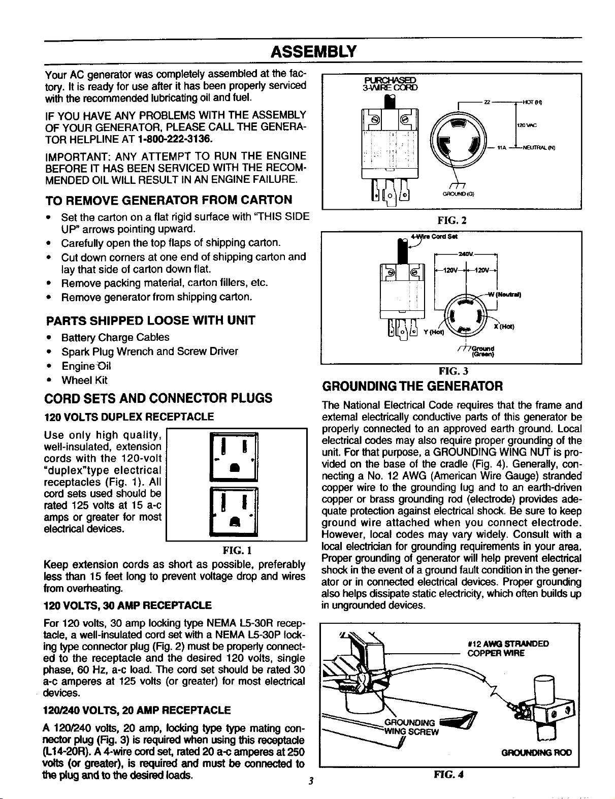
CORD SETS AND CONNECTOR PLUGS
120 VOLTS DUPLEX RECEPTACLE
Use only high quality, !
well-insulated, extension i
cords with the 120-volt
"duplex"type electrical
receptacles (Fig. 1). All
cord sets used should be
rated 125 volts at 15 a-c
amps or greater for most
electrical devices.
FIG. 1
Keep extension cords as short as possible, preferably
less than 15 feet long to prevent voltage drop and wires
from overheating.
120 VOLTS, 30 AMP RECEPTACLE
R.,RCI--I/_ED
3NtlRE COI_
120 V_3
; ; i:i , N_JIWAL(N)
GROUND(G)
FIG. 2
_vd Set
F)Tc-_d
(c-re_)
FIG. 3
GROUNDING THE GENERATOR
The National Electrical Code requires that the frame and
external electrically conductive parts of this generator be
properly connected to an approved earth ground. Local
electrical codes may also require proper grounding of the
unit. For that purpose, a GROUNDING WING NUT is pro-
vided on the base of the cradle (Fig. 4). Generally, con-
necting a No. 12 AWG (American Wire Gauge) stranded
copper wire to the grounding lug and to an earth-driven
copper or brass grounding rod (electrode) provides ade-
quate protection against electrical shock. Be sure to keep
ground wire attached when you connect electrode.
However, local codes may vary widely. Consult with a
local electrician for grounding requirements in your area.
Proper grounding of generator will help prevent electricel
shock inthe event of a ground fault condition inthe gener-
ator or in connected electrical devices. Proper grounding
also helps dissipate static electricity, which often builds up
in ungrounded devices.
For 120 volts, 30 amp locking type NEMA L5-30R recep-
tacle, a well-insulated cord set with a NEMA L5-30P lock-
ing type connector plug (Fig. 2) must be properly connect-
ed to the receptacle and the desired 120 volts, single
phase, 60 Hz, a-c load. The cord set should be rated 30
a-c amperes at 125 volts (or greater) for most electrical
devices.
120/240 VOLTS, 20 AMP RECEPTACLE
A 120/240 volts, 20 amp, locking type type mating con-
nector plug (Rg. 3) is required when using this receptacle
(L14-2OR). A 4-wire cord set, rated 20 a-c amperes at 250
volts (or greater), is required and must be connected to
the plug and to the desired loads.
#12 AWG STRANDED
COPPER WIRE
GROUNO4NGROD
3
FIG. 4
OPERATION
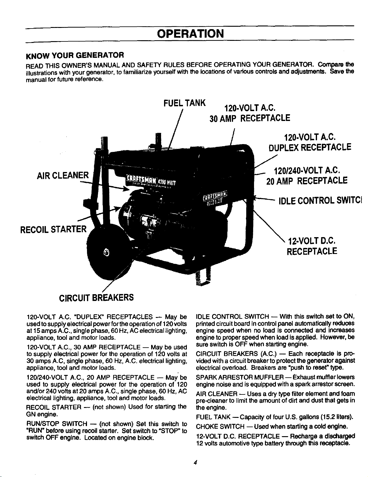
KNOW YOUR GENERATOR
READ THIS OWNER'S MANUAL AND SAFETY RULES BEFORE OPERATING YOUR GENERATOR. Compare the
illustrationswith your generator,tofamiliarizeyourselfwiththe locationsof variouscontrolsand adjustments. Save the
manualfor future reference.
AIR CLEANER
RECOILSTARTER
FUELTANK
120-VOLTA.C.
30AMP RECEPTACLE
120-VOLTA.C.
DUPLEXRECEPTACLE
120/240-VOLTA.C.
20AMP RECEPTACLE
IDLECONTROLSWlTCl
12-VOLTD.C.
RECEPTACLE
CIRCUITBREAKERS
120-VOLT A.C. "DUPLEX" RECEPTACLES -- May be
used to supply electrical Ix}wer for the operation of 120 volts
at 15 amps A.C., single phase, 60 Hz, AC electrical lighting,
appliance, tool and motor loads.
120-VOLT A.C., 30 AMP RECEPTACLE -- May be used
to supply electrical power for the operation of 120 volts at
30 amps A.C, single phase, 60 Hz, A.C. electrical lighting,
appliance, tool and motor loads.
120/240-VOLT A.C., 20 AMP RECEPTACLE -- May be
used to supply electrical power for the operation of 120
and/or 240 volts at 20 amps A.C., single phase, 60 Hz, AC
electrical lighting, appliance, tool and motor loads.
RECOIL STARTER -- (not shown) Used for starting the
GN engine.
RUN/STOP SWITCH -- (not shown) Set this switch to
=RUN" before using recoil starter. Set switch to "STOP" to
switch OFF engine. Located on engine block.
IDLE CONTROL SWITCH -- With this switch set to ON,
printed circuit board in control panel automatically reduces
engine speed when no load is connected and increases
engine to proper speed when load is applied. However, be
sure switch is OFF when starting engine.
CIRCUIT BREAKERS (A.C.) -- Each receptacle is pro-
vided with a circuit breaker to protect the generator against
electrical overload. Breakers are =push to reset" type.
SPARK ARRESTOR MUFFLER -- Exhaust muffler lowers
engine noise and is equipped with a spark arrestor screen.
AIR CLEANER -- Uses a dry type filter element and foam
pre-cleaner to limit the amount of dirt and dust that gets in
the engine.
FUEL TANK --Capacity of four U.S. gallons (15.2 liters).
CHOKE SWITCH -- Used when starting a cold engine.
12-VOLT D.C. RECEPTACLE -- Recharge a discharged
12 voltsautomotivetypebatterythroughthisreceptacle.
4
OPERATION
IF YOU HAVE ANY PROBLEMS OPERATING YOUR
GENERATOR, PLEASE CALL THE GENERATOR
HELPLINE AT 1-800-222-3136.
BEFORE STARTING ENGINE
ADD OIL:
Place generator on a level surface and remove one of
.they..ellowOil .FillCaps (Rg. 5) and add engine oil unti!
levm is at point owovernowmg. Check engine oil levee
before starting each time thereafter. If oil level is below
point of overflowing, fill to proper level. The recom-
mended oils include (during summer months) SAE 30
oil. SAE 10W-30 is an acceptable substitute. During
winter months use SAE 5W-20 or 5W-30. DO NOT
USE lOW-40. Crankcase oil capacity is about 720ml
with oil filter.
CAUTION: ANY AI"rEMPT TO CRANK OR START
THE ENGINE BEFORE IT HAS BEEN PROPERLY
SERVICED WITH THE RECOMMENDED OIL RE-
SULTS IN AN ENGINE FAILURE.
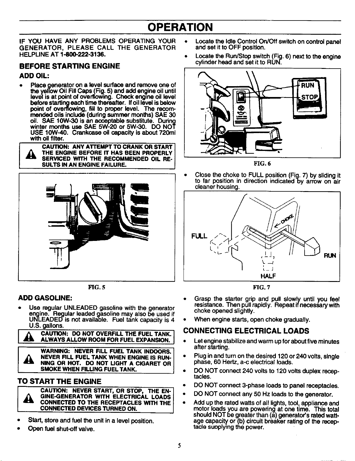
• Locate the Idle Control On/Off switch on control panel
and set it to OFF position.
• Locate the Run/Stop switch (Fig. 6) next to the engine
cylinder head and set it to RUN.
\
FIG. 6
• Close the choke to FULL position (Fig. 7) by sliding it
to far position in direction indicated by arrow on air
cleaner housing.
FIG. 5 FIG. 7
ADD GASOLINE:
• Use regular UNLEADED gasoline with the generator
engine. Regular leaded gasoline may also be used if
UNLEADED is not available. Fuel tank capacity is 4
U.S. gallons.
_1= CAUTION: DO NOT OVERFILL THE FUEL TANK.
ALWAYS ALLOW ROOM FOR FUEL EXPANSION.
WARNING: NEVER FILL FUEL TANK INDOORS.
NEVER RLL FUEL TANK WHEN ENGINE IS RUN-
NING OR HOT. DO NOT UGHT A CIGARET OR
SMOKE WHEN FILUNG FUEL TANK.
TO START THE ENGINE
CAUTION: NEVER START, OR STOP, THE EN-
GINE-GENERATOR WITH ELECTRICAL LOADS
CONNECTED TO THE RECEPTACLES WITH THE
CONNECTED DEVICES TURNED ON.
• Start, store and fuel the unit in a level position.
• Open fuel shut-off valve.
FULL
RUN
• Grasp the starter grip and pull slowly until you feel
resistance. Then pull rapidly. Repeatif necessarywith
choke opened slightly.
• When engine starts, open choke gradually.
CONNECTING ELECTRICAL LOADS
• Let engine stabilize and warm up for about five minutes
after starting.
• Plug in and turn on the desired 120 or 240 volts, single
phase, 60 Hertz, a-c electrical loads.
• DO NOT connect 240 volts to 120 volts duplex recep-
tacles.
• DO NOT connect 3-phase loads to panel receptacles.
• DO NOT connect any 50 Hz loads to the generator.
• Add up the rated watts of all lights tool appliance and
motor loads you are powering at one time. This total
should NOT be greater than (a) generator's rated watt-
age. capac!_ or (b) circuit breaker rating of the recep-
tac=esuoplymg the power.
OPERATION
STOPPING THE ENGINE
• Disconnect all electrical loads and let engine run at
no-load for about five minutes to stablize internal tom-
peratures of engine and generator.
• Tum off the engine by moving the Run/Stop switch to
STOP position.
OPERATING AUTOMATIC IDLE CONTROL
An Automatic Idle Control system provides greatly im-
proved fuel economy by operating the unitat itsnormal high
govemed speed only when electrical loads are plugged in
and tumed ON. The system consists of (a) an Idle Control
Circuit Board, (b) a Sensing Transformer, (c) an Electro-
magnet, and (d) an Idle Control Switch located on the
control panel (Fig. 8).
IDLE
CONTROL
FIG. 8
Engine-generator runs at high governed speed with Idle
Control Switch ON only when an electrical load is con-
nected to the generator and turned on. When the electrical
load isdisconnected, an Electromagnet isenergized to pull
the engine throttle control against itsidle stop. Engine then
runs at reduced (idle) speed.
The Electromagnet cannot be energized with Idle Control
Switch OFF, since its power circuit is open. Engine runs
at high govemed speed (about 3600 rpm) whether load(s)
are connected or not.
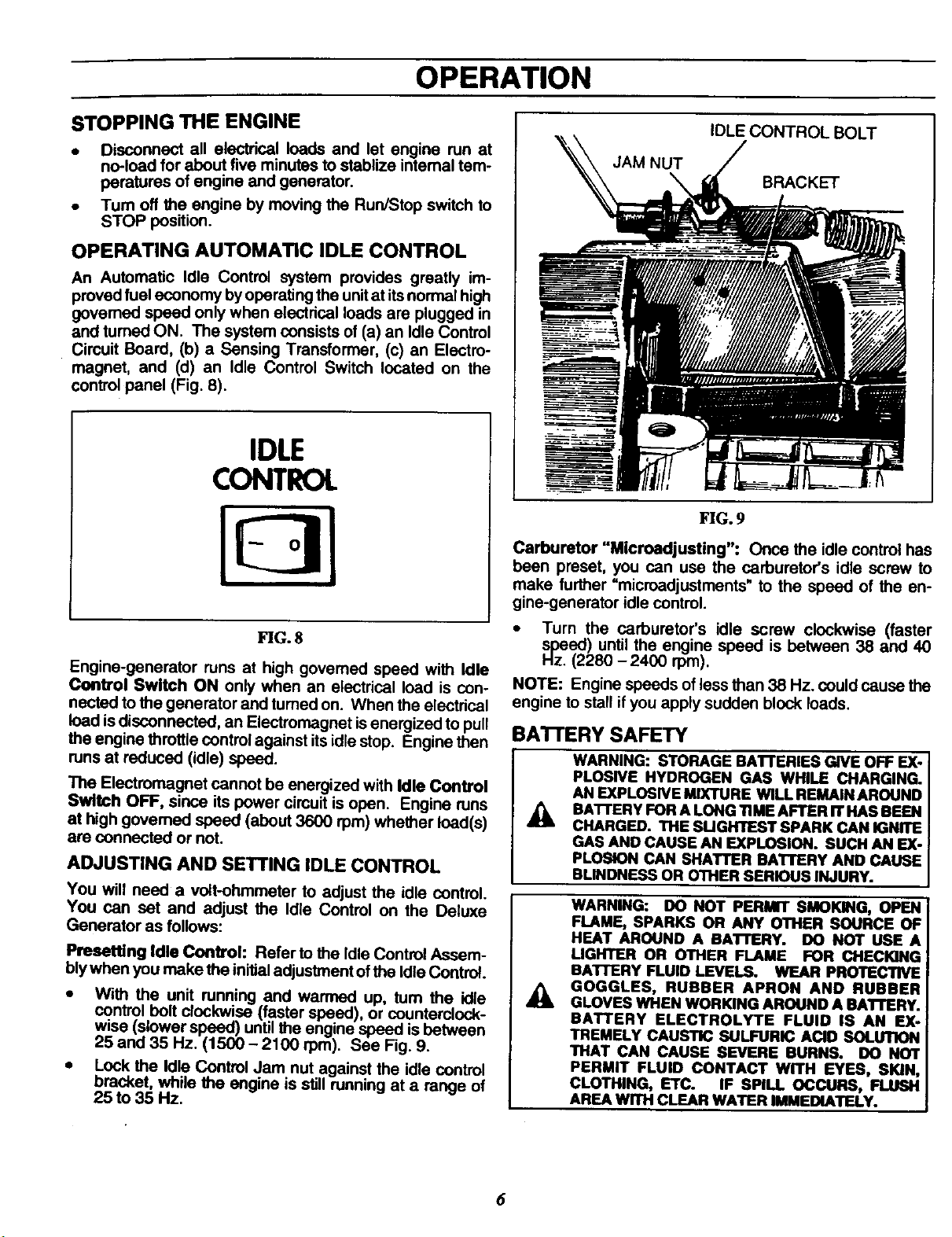
ADJUSTING AND SETTING IDLE CONTROL
You will need a volt-ohmmeter to adjust the idle control.
You can set and adjust the Idle Control on the Deluxe
Generator as follows:
Presetting Idle Control: Refer to the Idle Control Assem-
bly when you make the initial adjustment oi the idle Control.
• With the unit running and warmed up, tum the idle
control bolt clockwise (faster speed), or counterclock-
wise (slower speed) until the engine speed is between
25 and 35 Hz. (1500 - 2100 rpm). See Fig. 9.
• Lock the Idle Control Jam nut against the idle control
bracket, while the engine is still running at a range of
25 to 35 Hz.
IDLE CONTROL BOLT
JAM NUT
BRACKET
FIG.9
Carburetor "Microadjusting": Once the idle control has
been preset, you can use the carburetor's idle screw to
make further =microadjustments" to the speed of the an-
gine-generator idle control.
• Turn the carburetor's idle screw clockwise (faster
_4Oezed ) until the engine speed is between 38 and 40
(2280 - 2400 rpm).
NOTE: Engine speeds of less than 38 Hz. could cause the
engine to stall if you apply sudden block loads.
BA'I-rERY SAFETY
WARNING: STORAGE BAI"rERIES GIVE OFF EX-
PLOSIVE HYDROGEN GAS WHILE CHARGING.
AN EXPLOSWE MIXTURE WILL REMAIN AROUND
BATTERY FOR A LONG 11MEAFTER IT HAS BEEN
A
CHARGED. THE SUGHTESTSPARK CAN IGNITE
GAS AND CAUSE AN EXPLOSION. SUCH AN EX-
PLOSION CAN SHATTER BATTERY AND CAUSE
BLINDNESS OR OTHER SERIOUS INJURY.
WARNING: DO NOT PERMIT SMOKING, OPEN
FLAME, SPARKS OR ANY OTHER SOURCE OF
HEAT AROUND A BAI"rERY. DO NOT USE A
UGHTER OR OTHER FLAME FOR CHECKING
BATfERY FLUID LEVELS. WEAR PROTECTIVE
GOGGLES, RUBBER APRON AND RUBBER
GLOVES WHEN WORKING AROUND A BATrERY.
BATTERY ELECTROLYTE FLUID IS AN EX-
TREMELY CAUSTIC SULFURIC ACID SOLUTION
THAT CAN CAUSE SEVERE BURNS. DO NOT
PERMIT FLUID CONTACT WITH EYES, SKIN,
CLOTHING, ETC. IF SPILL OCCURS, FLUSH
AREA WITH CLEAR WATER IMMEDIATELY.
6
OPERATION
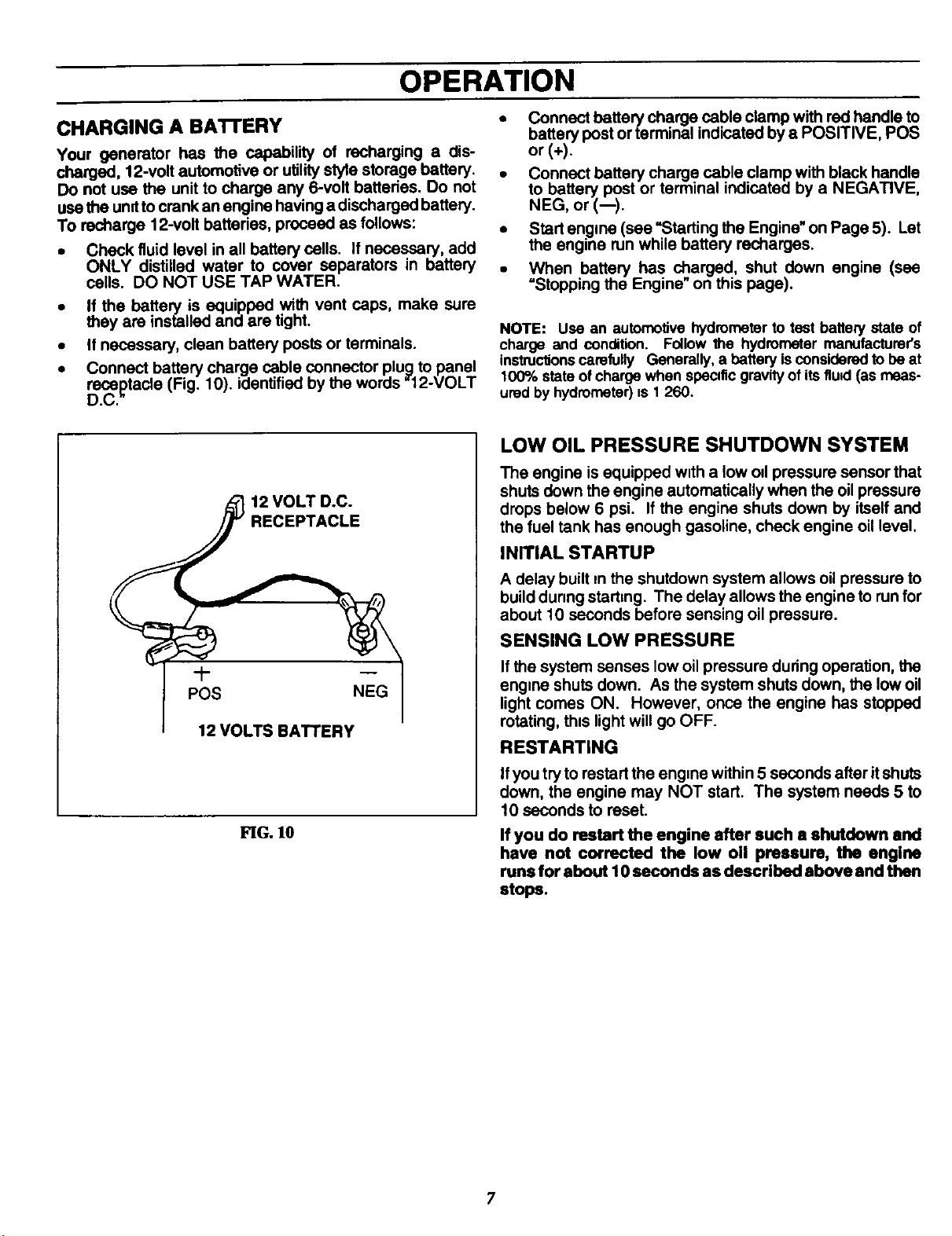
CHARGING A BA1TERY
Your generator has the capability of recharging a dis-
charged, 12-volt automotive or utility style storage battery.
Do not use the unit to charge any 6-volt batteries. Do not
use the unit to crank an engine having a discharged battery.
To recharge 12-volt battedas, proceed as follows:
• Check fluid level in all battery cells. If necessary, add
ONLY distilled water to sever separators in battery
cells. DO NOT USE TAP WATER.
• If the battery is equipped with vent caps, make sure
they are installed and are tight.
• If necessary, clean battery posts or terminals.
• Connect battery charge cable connector plug to panel
recaptacle (Fig. 10). identified by the words =12-VOLT
D.C.
Connectbatterycharge cable clamp with red handle to
battery post or terminal indicated by a POSITIVE, POS
or(*).
• Connect battery charge cable clamp with black handle
to battery post or terminal indicated by a NEGATIVE,
NEG, or (--).
. Start en.g=ne(see =Starting the Engine" on Page 5). Let
the engine run while battery recharges.
• When battery has charged, shut down engine (see
=Stopping the Engine" on this page).
NOTE: Use an automotive hydrometer to test batterystate of
charge and condition. Follow the hydrometer manufacturer's
instruc_onscarefully Generally,a battery isconsidered tobe at
100% stateof charge when speQtic gravityof itsflu_ (as meas-
ured by hydrometer)is 1 260.
LOW OIL PRESSURE SHUTDOWN SYSTEM
The engine is equipped w_tha low od pressure sensor that
shuts down the engine automatically when the oil pressure
drops below 6 psi. If the engine shuts down by itself and
the fuel tank has enough gasoline, check engine oil level.
INITIAL STARTUP
A delay built m the shutdown system allows oil pressure to
build dunng starting. The delay allows the engine to run for
about 10 seconds before sensing oil pressure.
SENSING LOW PRESSURE
If the system senses low oil pressure during operation, the
eng=ne shuts down. As the system shuts down, the low oil
light comes ON. However, once the engine has stopped
rotating, this light will go OFF.
RESTARTING
FIG. 10
Ifyou try to restart the eng=ne within 5 seconds after itshuts
down, the engine may NOT start. The system needs 5 to
10 seconds to reset.
If you do restart the engine after such a shutdown and
have not corrected the low oil pressure, the engine
runs for about 10 seconds as described above and then
stops.
7
OPERATION
DON'T OVERLOAD THE GENERATOR
Overloading a generator in excess of its rated wattage
capacity can result in damage to generator and to con-
nected electrical devices. Observe the following, to pre-
vent overloading the unit:
• Add up the total wattage of all electrical devices to be
connected at one time. This total should NOT be
greater than the generator's wattage capacity.
• The rated wattage of lights can be taken from light
bulbs. The rated wattage of tools, appliances and
motors can usual!y be found on a data plate or decal
affixed to the device.
• If the appliance, tool or motor does not give wattage,
mulitply !20 volts Umas ampere rating to detarmnne
watts (volts x amps = watts).
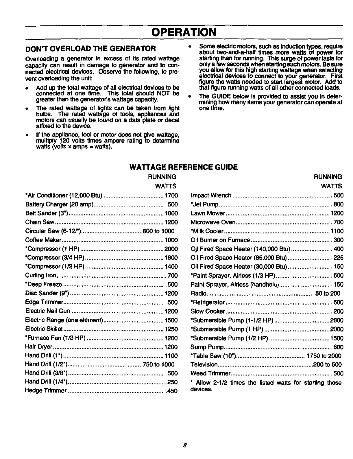
WATTAGE REFERENCE GUIDE
RUNNING
WA'I-rS
*Air Conditioner (12,000 Btu) .................................... 1700
Battery Charger (20 amp) .......................................... 500
Belt Sander (3") ......................................................... 1000
Chain Saw ................................................................. 1200
Cimular Saw (6-12/') ..................................... 800 to 1000
Coffee Maker ............................................................. 1000
"Compressor (1 HP) .................................................. 2000
*Compressor (3/4 HP) ............................................... 1800
*Compressor (1/2 HP) ............................................... 1400
Curling Iron ................. ................................................ 700
"Deep Freeze ............................................................. 500
Disc Sander (9") ........................................................ 1200
Edge Trimmer ............................................................. 500
Electric Nail Gun ....................................................... 1200
Electric Range (one element) .................................... 1500
Electdc Skillet. .......................................................... 1250
*Furnace Fan (1/3 HP) .............................................. 1200
Hair Dryer .................................................................. 1200
Hand Drill (1")............................................................ 1100
Hand Drill (1/2') ............................................ 750 to 1000
Hand Drill (3/8") .......................................................... 500
Hand Ddll (1/4') ........................................................... 250
Hedge Trimmer .......................................................... 450
Some electric motors, such as induction types, require
about two-and-a-half times more watts of power for
s_rtin_ than for running. This surge of power lasts for
omy a few seconds when starting such motors. Be sure
you allow ;or this high starting wattage when selecting
electrical devices to connect to your generator. First
figure the watts needed to start largest motor. Add to
that figure running watts of all other connected loads.
The GUIDE below is provided to assist you in deter-
mining how many items your generator can operate at
one time.
RUNNING
WATTS
Impact Wrench ........................................................... 500
*Jet Pump ................................................................... 800
Lawn Mower .............................................................. 1200
Microwave Oven ......................................................... 700
*Milk Cooler ............................................................... 1100
Oil Burner on Fumaca ................................................ 300
Oil Fired Space Heater (140,000 Btu) ........................ 400
Oil Fired Space Heater (85,000 Btu) .......................... 225
Oil Fired Space Heater (30,000 Btu) .......................... 150
*Paint Sprayer, Airless (1/3 HP) ................................. 600
Paint Sprayer, Aidess (handhelu) ............................... 150
Radio ................................................................ 50 to 200
"Refrigerator ............................................................... 600
Slow Cooker ............................................................... 200
*Submersible Pump (1-1/2 HP) ................................. 2800
*Submersible Pump (1 HP) ....................................... 2000
*Submersible Pump (1/2 HP) .................................... 1500
Sump Pump ................................................................ 600
*Table Saw (10")......................................... 1750 to 2000
Television ........................................................ .200 to 500
Weed Trimmer ............................................................ 500
* Allow 2-1/2 times the listed watts for starting these
devices.
8
MAINTENANCE
GENERAL RECOMMENDATIONS
The Owner/Operator is responsible for making sure that all
periodic maintenance tasks are completed on a timely
basis; that all discrepancies are corrected; and that the unit
is kept ctean and property stored. Never operate a dam-
aged or defective generator.
GENERATOR MAINTENANCE
Generator maintenance consists of keeping the unit clean
and dry. Operate and store the unit in a clean dry envior-
ment where it will not be exposed to exceesive dust, dirt,
moisture or any corrosive vapors. Cooling air slots in the
generator must not become dogged with snow, leaves or
any other foreign material.
Check the cleenliness of the generator fraquentiy and clean
when dust, dirt, oil, moisture or other foreign substances
are visible on its exterior surface.
NOTE: We DO NOT recommend usinga garden hose to clean
thegenerator. Water canenterthe enginefuelsystemand cause
problems. In addition, if water entem the generator through
coolingair slots,some of the water willbe retained in voids and
cracksof the rotorand statorwindinginsulation. Water and dirt
buildupon the generator internal windingswill eventually de-
creasethe insulationresistanceof thesewindings.
TO CLEAN THE GENERATOR:
• Use a damp cloth to wipe exterior surfaces clean.
• Use a soft, bristle brush to loosen caked on dirt,oil, etc.
• A vacuum cleaner may be used to pick up loose dirt
and debris.
Low pressure air (not to exceed 25 psi) may be used
to blow away dirt. Inspect cooling air slots and opening
on the generator. These openings must be kept clean
and unobstructed.
CAUTION: NEVER INSERT ANY OBJECT OR
TOOL THROUGH THE AIR COOLING SLOTS, EVEN
IF THE ENGINE IS NOT RUNNING. DAMAGE TO
THE UNIT OR PERSONAL INJURY MAY RESULT.
ENGINE MAINTENANCE
CHECKING OIL LEVEL
See OPERATION sectionon Page 4 forinformationon checking
oillevel. Oil levelshould be checked before each use orat least
every eight hours ofoperation. Keep oillevel maintained.
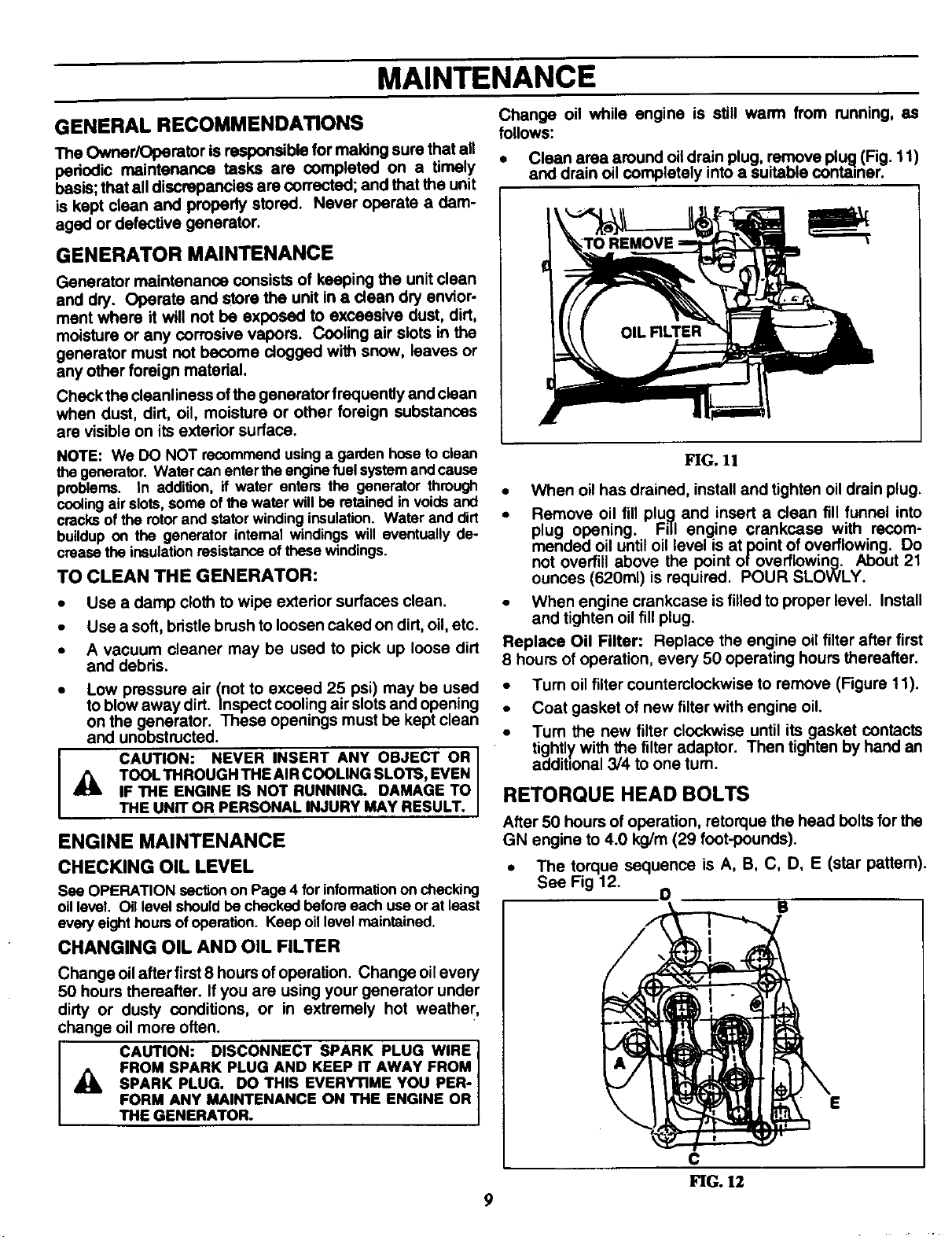
CHANGING OIL AND OIL FILTER
Change oil while engine is still warm from running, as
follows:
• Clean area around oil drain plug, remove plug (Fig. 11)
and drain oil completely into a suitable container.
OIL FILTER
I
A
FIG. 11
• When oil has drained, install and tighten oil drain plug.
• Remove oil fill plug and insert a clean fill funnel into
plug opening. Fill engine crankcase with recom-
mended oil until oil level is at point of overflowing. Do
not overfill above the point of overflowing. About 21
ounces (620ml) is required. POUR SLOWLY.
• When engine crankcase is filled to proper level. Install
and tighten oil fill plug.
Replace Oil Filter: Replace the engine oil filter after first
8 hours of operation, every 50 operating hours thereafter.
• Turn oil filter counterclockwise to remove (Figure 11).
• Coat gasket of new filter with engine oil.
• Turn the new filter clockwise until its gasket contacts
tightly with the filter adaptor. Then tighten by hand an
additional 3/4 to one turn.
RETORQUE HEAD BOLTS
After 50 hours of operation, retorque the head bolts for the
GN engine to 4.0 kg/m (29 foot-pounds).
• The torque sequence is A, B, C, D, E (star pattern).
See Fig 12.
O
B
Change oilafter first 8 hours of operation. Change oil every
50 hours thereafter. If you are using your generator under
dirty or dusty conditions, or in extremely hot weather,
change oil more often.
FROM SPARK PLUG AND KEEP IT AWAY FROM
SPARK PLUG. DO THIS EVERYTIME YOU PER-
J ,_ CAUTION: DISCONNECT SPARK PLUG WIRE
FORM ANY MAINTENANCE ON THE ENGINE OR
THE GENERATOR,
E
C
FIG. 12
9
MAINTENANCE
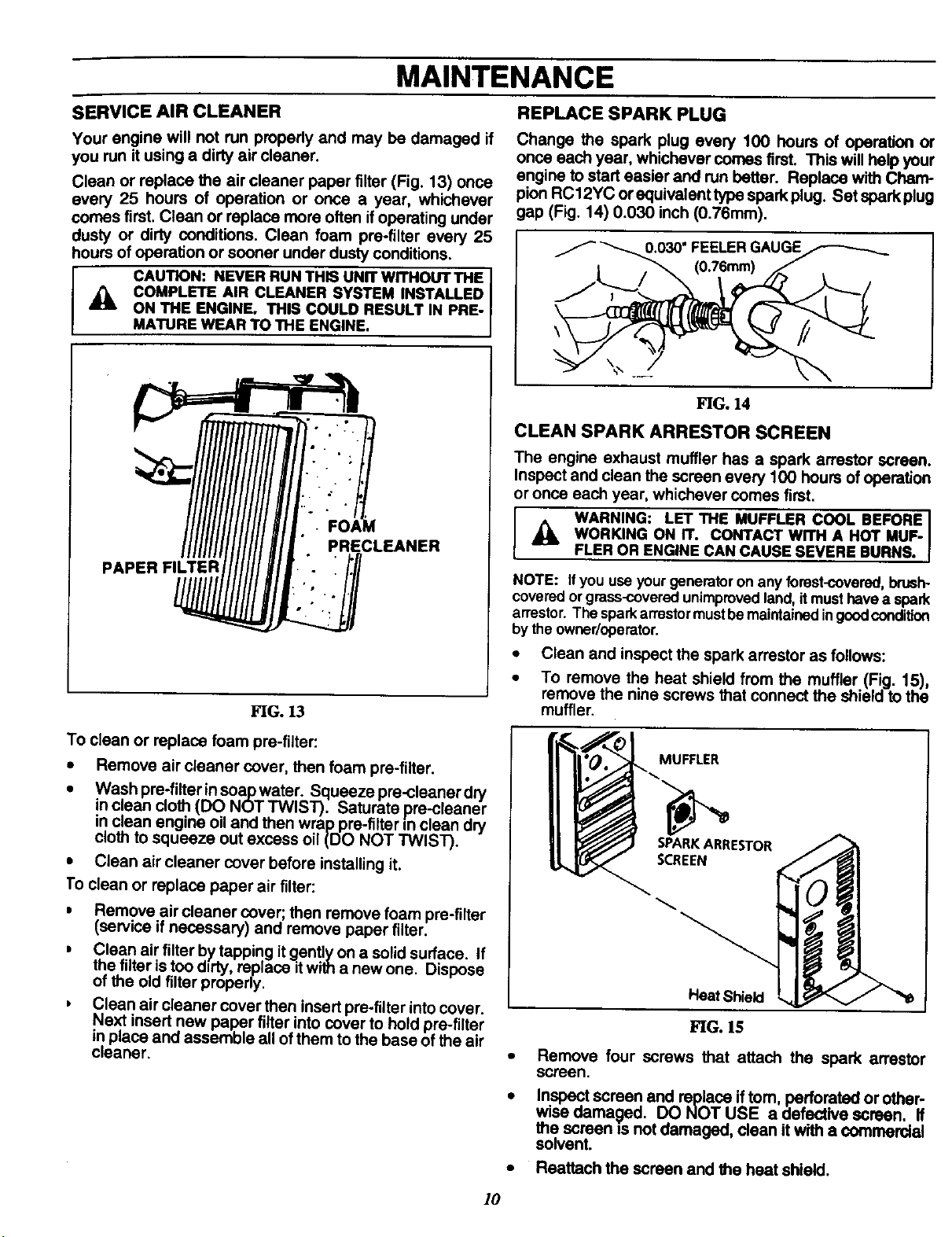
SERVICE AIR CLEANER REPLACE SPARK PLUG
Your engine will not run properly and may be damaged if
you run it using a dirty air cleaner.
Clean or replace the air cleaner paper filter (Fig. 13) once
every 25 hours of operation or once a year, whichever
comes first. Clean or replace mere often if operating under
dusty or dirty conditions. Clean foam pre-filter every 25
hours of operation or sooner under dusty conditions.
A COMPLETE AIR CLEANER SYSTEM INSTALLED
I CAUTION: NEVER RUN THIS UNIT WITHOUT THE
ON THE ENGINE. THIS COULD RESULT IN PRE-
MATURE WEAR TO THE ENGINE.
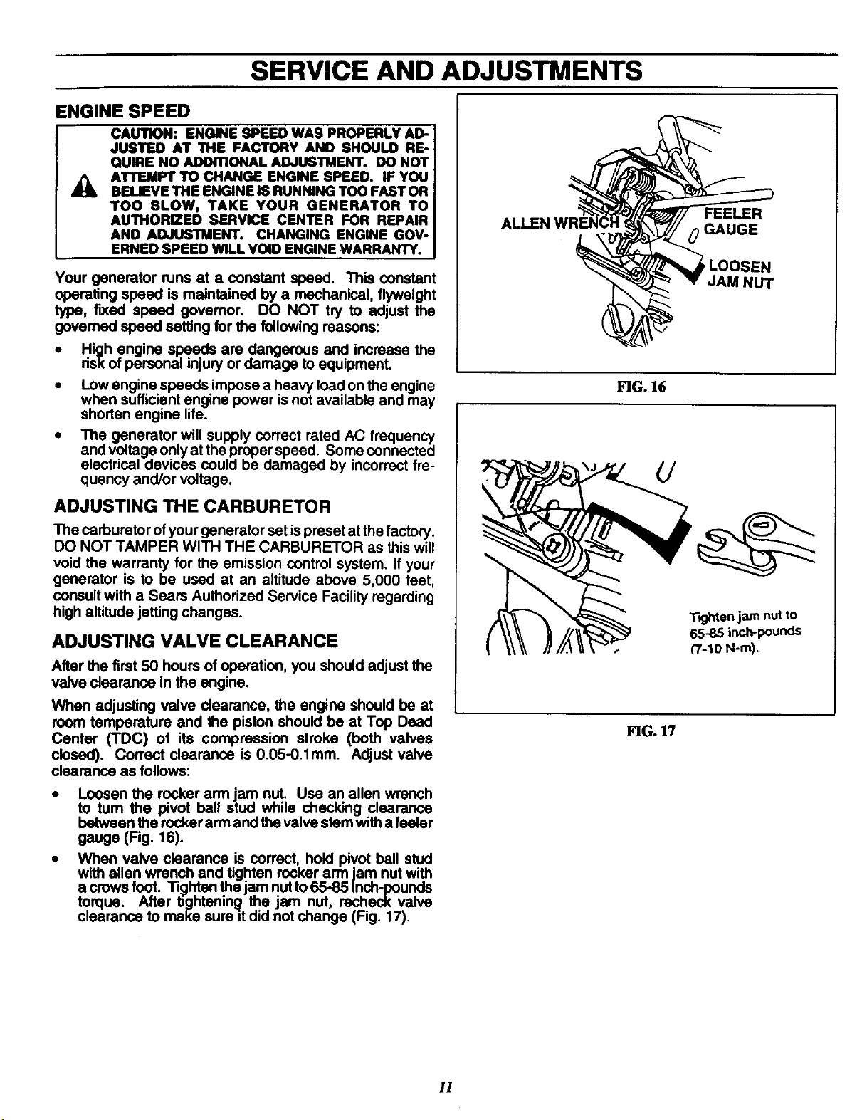
Change the spark plug every 100 hours of operation or
once each year, whichever comes first. This will help your
engine to start easier and run better. Replace with Cham-
pion RC12YC or equivalent type spark plug. Set spark plug
gap (Fig. 14) 0.030 inch (0.76mm).
/ "_.030" FEELERGAUGE
/_ (0.76mm)
FIG. 14
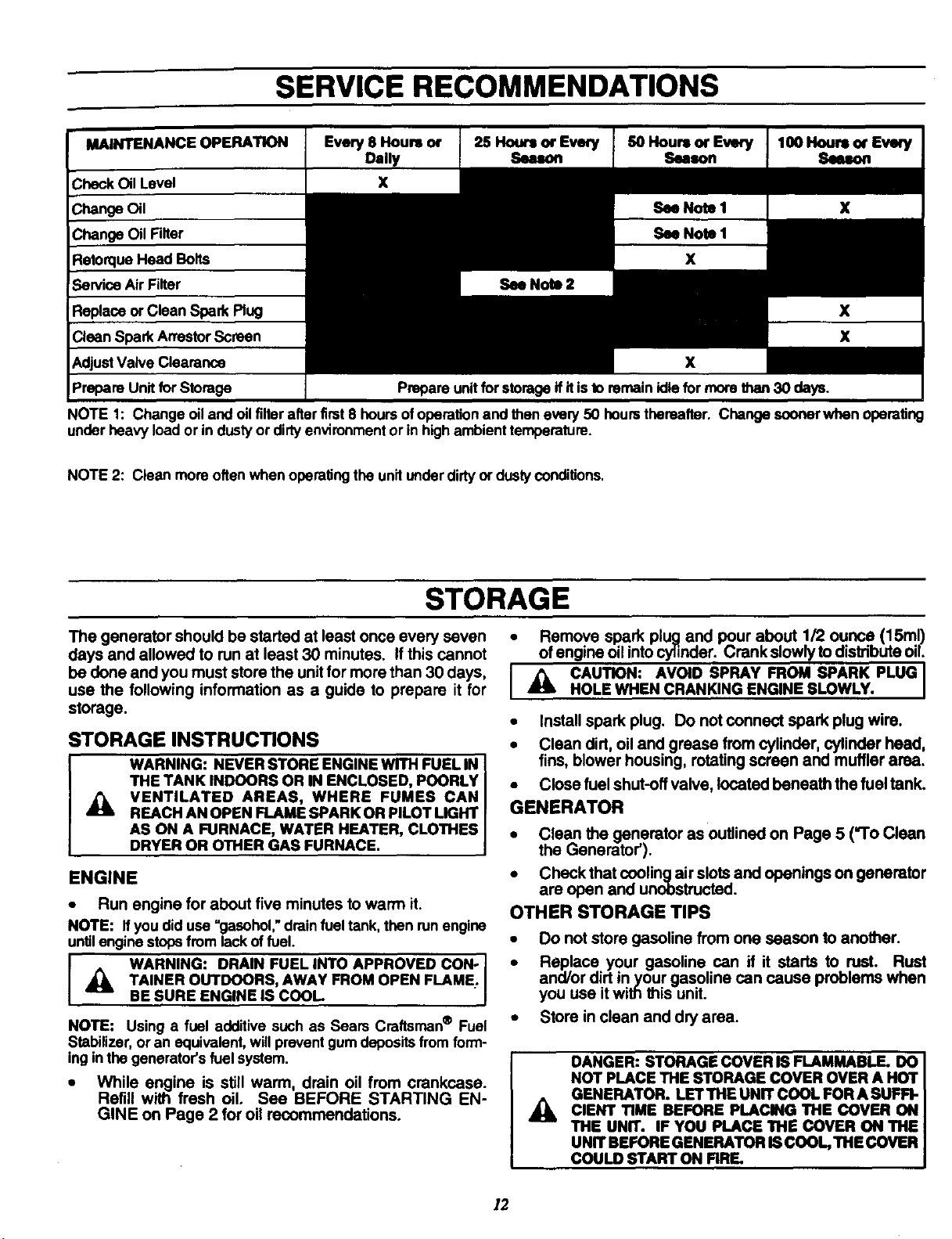
CLEAN SPARK ARRESTOR SCREEN
The engine exhaust muffler has a spark arrestor screen.
Inspect and clean the screen every 100 hours of operation
or once each year, whichever comes first.
PRECLEANER
PAPER FILTER
FIG. 13
To clean or replace foam pre-filter:
* Remove air cleaner cover, then foam pre-tilter.
• Wash pre-filter in soap water. Squeeze pre-c eaner dry
in clean cloth (DO NOTTWlST). Saturata pre-c eaner
in clean engine oil and then wrap pre-ti tern clean dry
cloth to squeeze out excess oil (DO NOT TWIST).
• Clean air cleaner cover before installing it.
To clean or replace paper air filter:
• Remove air cleaner cover; then remove foam pre-fi ter
Iservice if necessary) and remove paper tilter.
, Clean air filter bytapping itgently on a solid surface. If
the filter is too durty replace itwith a new one. D spose
of the o d f Iter properly.
b Clean air cleaner cover then insert pre-filter into cover.
Next insert new paper filter into cover to hod pre-filter
in place and assemble all of them to the base of the air
cleaner.
A WORKING ON IT. CONTACT WITH A HOT MUF-
p WARNING: LET THE MUFFLER COOL BEFORE I
NOTE: If you useyourgenerator on any forest-covered,brush°
coveredor grass-coveredunimprovedland, itmust have a spark
arrestor.The sparkarrestormustbe maintainedingoodcondition
by the owner/operator.
• Clean and inspect the spark arrestor as follows:
• To remove the heat shield from the muffler (Fig. 15),
• Reattach the screen and the heat shield.
FLER OR ENGINE CAN CAUSE SEVERE BURNS.
remove the nine screws that connect the shield to the
muffler.
MUFFLER
SPARKARRESTOR
SCREEN
Heat Shield
FIG. 15
Remove four screws that attach the spark arrestor
screen.
Inspect screen and replace if tom, perforated or other-
wise oamaged. DO NOT USE a defective screen. If
the screen is not damaged, clean it with a commercial
solvent.
10
SERVICE AND ADJUSTMENTS
ENGINE SPEED
CAUTION: ENGINE SPEED WAS PROPERLY AD-
JUSTED AT THE FACTORY AND SHOULD RE-
QUIRE NO ADDITIONAL ADJUSTMENT. DO NOT
AI"rEMPT TO CHANGE ENGINE SPEED. IF YOU
BEUEVE THE ENGINE IS RUNNING TOO FAST OR
TOO SLOW, TAKE YOUR GENERATOR TO
AUTHORIZED SERVICE CENTER FOR REPAIR
ANO ADJUSTMENT. CHANGING ENGINE GOV-
ERNED SPEED WILL VOID ENGINE WARRANTY.
Your generator runs at • constant speed. This constant
operating speed is maintained by a mechanical, flyweight
type, fixed speed governor. DO NOT try to adjust the
govemed speed setting for the following reasons:
• High engine speeds are dangerous and increase the
dsk of personal injury or damage to equipment.
• Low engine speeds impose a heavy load on the engine
when sufficient engine power is not available and may
shorten engine life.
• The generator will supply correct rated AC frequency
and voltage only at the proper speed. Some connected
electrical devices could be damaged by incorrect fre-
quency and/or voltage.
ALLEN
FEELER
0 GAUGE
_LOOSEN
JAM NUT
FIG. 16
ADJUSTING THE CARBURETOR
The carburetor of your generator set is preset at the factory.
DO NOT TAMPER WITH THE CARBURETOR as this will
void the warranty for the emission control system. If your
generator is to be used at an altitude above 5,000 feet,
consult with a Sears Authorized Service Facility regarding
high altitude jetting changes.
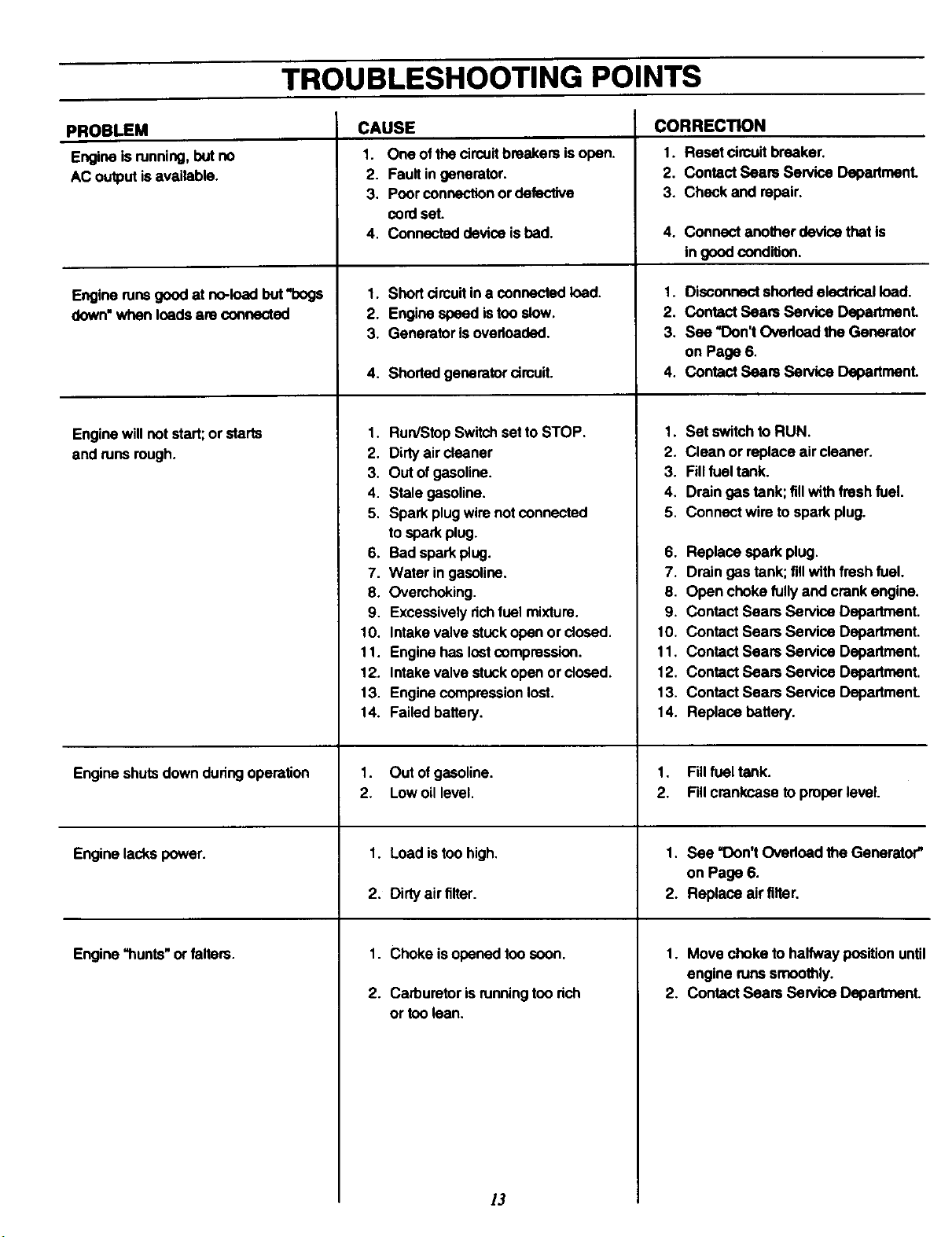
ADJUSTING VALVE CLEARANCE
After the first 50 hours of operation, you should adjust the
valve clearance in the engine.
When adjusting valve clearanca, the engine should be at
room temperature and the piston should be at Top Dead
Center ('rDC) of its compression stroke (both valves
closed). Correct clearance is 0.05-0.1mm. Adjust valve
clearance as follows:
• Loosen the rocker arm jam nut. Use an allen wrench
to turn the pivot ball stud while checking clearance
between the rocker arm and the valve stem with a feeler
gauge (Fig. 16).
• When valve clearance is correct, hold pivot bell stud
with allen wrench and tighten rocker arm jam nut with
a crows foot. Tighten the jam nut to65-85 =nch-pounds
torque. After tightenin_,l the jam nut, recheck valve
clearance to make sure itdid not change (Fig. 17).
"F_jhten]am nutto
65-85 inch-pounds
("/-10 N-m).
FIG. 17
1!
SERVICE RECOMMENDATIONS
MAINTENANCE OPERATION Every 8 Hours or 25 Hours or Every SOHours or Every 100 Hours or Every
NOTE 1: Change oil and oil filterafterfirst8 hoursofoperationand then every 50 hoursthereafter. Change soonerwhen operating
underheavy load or in dustyor dirtyenvironmentor in highambienttemperature.
NOTE 2: Clean more often when operatingthe unitunderdirtyordustyconditions.
STORAGE
The generator should be started at least once every seven
days and allowed to run at least 30 minutes. If this cannot
be done and you must store the unit for more than 30 days,
use the following information as a guide to prepare it for
storage.
STORAGE INSTRUCTIONS
WARNING: NEVER STORE ENGINE WITH FUEL IN
THE TANK INDOORS OR IN ENCLOSED, POORLY
,_ VENTILATED AREAS, WHERE FUMES CAN
REACH AN OPEN FLAME SPARK OR PILOT LIGHT
AS ON A FURNACE, WATER HEATER, CLOTHES
DRYER OR OTHER GAS FURNACE.
ENGINE
• Run engine for about five minutes to warm it.
NOTE: Ifyou did use =gasohol,"drainfuel tank, then runengine
untilenginestopsfrom lack of fuel.
_ TAINER OUTDOORS, AWAY FROM OPEN
WARNING: DRAIN FUEL INTO APPROVED CON- ] •
BE SURE ENGINE IS COOL J
NOTE: Using a fuel additive such as Sears Craftsman® Fuel •
Stabilizer,or an equivalent,will preventgum depositsfrom form-
ingin the generator's fuel system.
• While engine is still warm, drain oil from crankcase.
Refill with fresh oil. See BEFORE STARTING EN-
GINE on Page 2 for oil recommendations.
FLAME;
I
• Remove spark plug and pour about 1/2 ounce (15ml)
ofengine oil intocylinder. Crank slowly to distribute oil
I _ CAUTION: AVOID SPRAY FROM SPARK PLUG
• Install spark plug. Do not connect spark plug wire.
• Clean dirt, oil and grease from cylinder, cylinder head,
• Close fuel shut-off valve, located beneath the fuel tank.
GENERATOR
• Clean the generator as outlined on Page 5 ("To Clean
• Check that cooling air slots and openings on generator
OTHER STORAGE TIPS
HOLE WHEN CRANKING ENGINE SLOWLY.
fins, blower housing, rotating screen and muffler area.
the Generator').
are open and unobstructed.
Do not store gasoline from one season to another.
Replace your gasoline can if it starts to rust. Rust
and/or dirt in your gasoline can cause problems when
you use it with this unit.
Store in clean and dry area.
DANGER: STORAGE COVER IS FLAMMABLE. DO
NOT PLACE THE STORAGE COVER OVER A HOT
GENERATOR. LETTHE UNIT COOL FOR A SUFFI-
_k CIENT TIME BEFORE PLACING
THE UNIT. IF YOU PLACE THE COVER ON THE
UNIT BEFORE GENERATOR ISCOOL, THE COVER
COULD START ON RRE.
THE
COVER ON
12
TROUBLESHOOTING POINTS
PROBLEM
Engineis running,10utno
AC outputisavailable.
Engine runs good at no-loadbut"bogs
down"when loadsare connected
Enginewillnot start;orstarts
and runsrough.
CAUSE
CORRECTION
1. One ofthe circuitbreakers isopen.
2. Fault ingenerator.
3. Poor connectionor defective
cordset.
4. Connected device is bad.
1.
Shortcircuitin a connectedload. 1.
2.
Enginespeed istoo slow. 2.
3.
Generator isoverloaded. 3.
4.
Shoded generatorcircuit. 4,
1.
Run/Stop Switchset to STOP. 1.
2.
Dirty air cleaner 2.
3.
Outof gasoline. 3.
4.
Stale gasoline. 4.
5.
Spark plugwire notconnected 5.
to spark plug.
.
Bad spark plug. 6.
7.
Water ingasoline. 7.
8.
Overchoking. 8.
9.
Excessivelyrichfuel mixture. 9.
10.
Intakevalve stuckopenor dosed. 10.
11.
Enginehas lostcompression. 11.
12. Intakevalve stuck opan orclosed. 12.
13. Enginecompressionlost. 13.
14. Failed battery. 14.
1. Reset circuitbreaker.
2. Contact Sears Service DepadmenL
3. Check and repair.
4.
Connect anotherdevice that is
in goodcondition.
Disconnectshorted electricalload.
Contact Sears Service Department.
See "Don't Ovedoadthe Generator
on Page 6.
ContactSears Service Department.
Set switchto RUN.
Clean or replaceair cleaner.
Fillfuel tank.
Drain gastank; fillwith freshfuel.
Connect wire to spark plug.
Replace spark plug.
Drain gas tank; till withfreshfuel.
Open choke fully and crankengine.
ContactSears Service Department.
ContactSears Service Department.
ContactSears Service Department.
ContactSears Service Department.
ContactSears Service Department.
Replace battery.
Engine shutsdowndunngoperation
Engine lackspower.
Engine "hunts" orfaltera.
1. Out of gasoline. 1.
2. Lowoil level. 2.
1. Load istoo high. 1.
2. Dirtyair filter. 2.
1. Choke isopened too soon. 1,
2. Carburetorisrunningtoo rich 2.
or toolean.
13
Fillfuel tank.
Fillcrankcase to properlevel.
See "Don'tOverload the Generator"
on Page 6.
Replace air filter.
Move choke to halfway positionuntil
engine runs smoothly.
ContactSears Service Department.
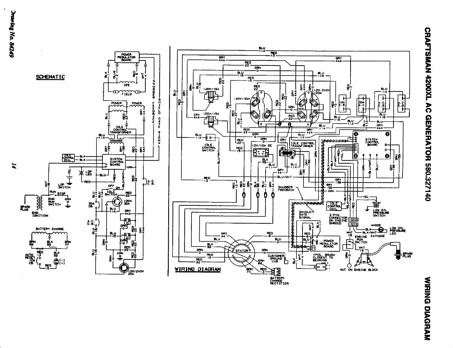
W_[RZNG D| AGRAH
BtTTERy
I_CT]F JER
 Loading...